

LG RNOE-B501A, RNZE-B501A Owner's Manual

OWNER’S MANUAL
Network Camera
Please read this manual carefully before operating
your set and retain it for future reference.
MODELS
RNOE-B501A
RNZE-B501A
*5PKA00129J*
1706 (V1.0)

2
Contents
Introduction ......................................................................................3
Features Chart ......................................................................3
Installation (RNOE-B501A) .............................................................4
Part Names and Functions ...................................................4
Connection ...........................................................................5
Connecting Network ................................................5
Connecting Power Source ........................................ 5
To use the PoE (Power over Ethernet) device .........5
Connecting Display Device ......................................5
Connecting Microphone and Speaker Device ..........5
Connecting Alarm Device.........................................6
Connecting PTZ Device ............................................6
Using the SD card .................................................................7
To insert the SD card ...............................................7
Remove the SD card .................................................7
Recommended the SD card specication ................ 7
Mounting the Lens ...............................................................8
Focus adjustment .................................................................8
Camera Installation ..............................................................8
Installation (RNZE-B501A) ..............................................................9
Part Names and Functions ...................................................9
Connection .........................................................................10
Connecting Network ..............................................10
Connecting Power Source ......................................10
Connecting Microphone and Speaker Device ........10
Connecting Alarm Device.......................................10
Using the micro SD card .....................................................11
To insert the micro SD card ...................................11
Remove the micro SD card .....................................11
Recommended the micro SD card specication ....11
Wall mount (optional) ........................................................12
Operation and settings ...................................................................13
Before using the system ....................................................13
Recommended PC Requirements .......................................13
Accessing the LG IP device .................................................14
LG Smart Web Viewer Overview ........................................15
Live View ................................................................15
System Settings .....................................................17
Playback ..............................................................................18
Search recording les.............................................18
Download recording les .......................................18
Playback .................................................................18
Recording snapshot ................................................18
Video clip ................................................................18
Four screen play .....................................................19
Full screen ..............................................................19
Switch mode ...........................................................19
Log searching ......................................................................20
Conguring the LG Network Camera Device .....................21
Accessing the Conguration menu ........................21
Conguration ......................................................................21
Conguration menu overview ................................21
Audio video set ......................................................22
Dome Set / Camera Set .........................................23
VCA ...................................................................28
OSD ................................................................... 32
Storage Management ............................................33
Network Management ...........................................35
User Management ..................................................38
Alarm Management ................................................38
Mask Alarm ............................................................39
PTZ Management ...................................................40
Advance Set ...........................................................40
Reference ........................................................................................42
Troubleshooting ..................................................................42
OPEN SOURCE SOFTWARE NOTICE ................................44
Specications .....................................................................45

Introduction 3
The LG Network Camera is designed to use on an Ethernet network and must be assigned an IP address to make it accessible.
This manual contains instructions on how to install and manage the LG Network Camera in your networking environment. Some knowledge of
networking environments would be beneficial to the reader.
Note that design and specification of this unit may change from the manual as quality and improvement without prior notice.
Should you require any technical assistance, please contact authorized service center.
Features Chart
This table shows the differences between the models.
Item SD card RS-485 Audio input Audio output
RNOE-B501A SD card Yes Yes Yes
RNZE-B501A Mirco SD card No Yes Yes
Introduction
4 Installation
Installation (RNOE-B501A)
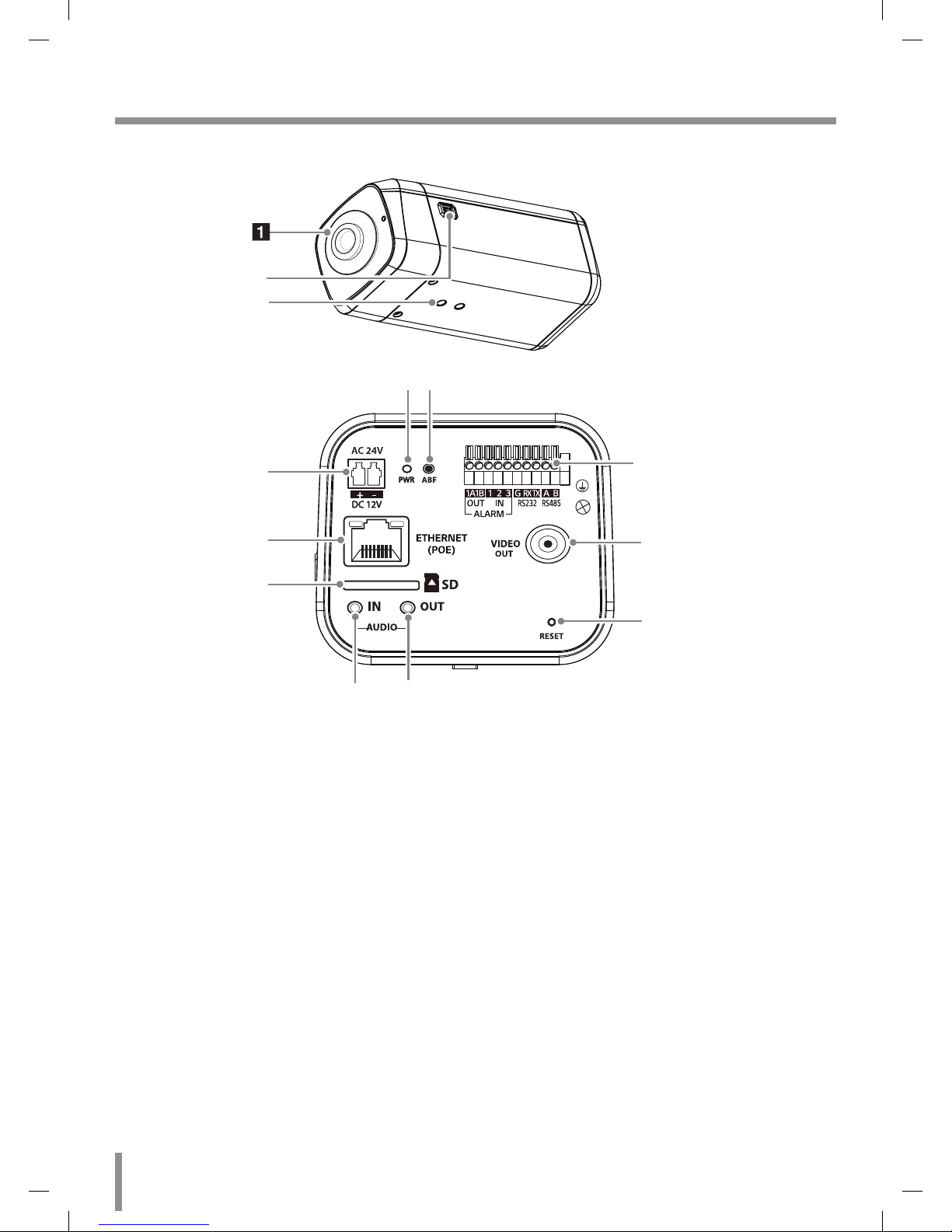
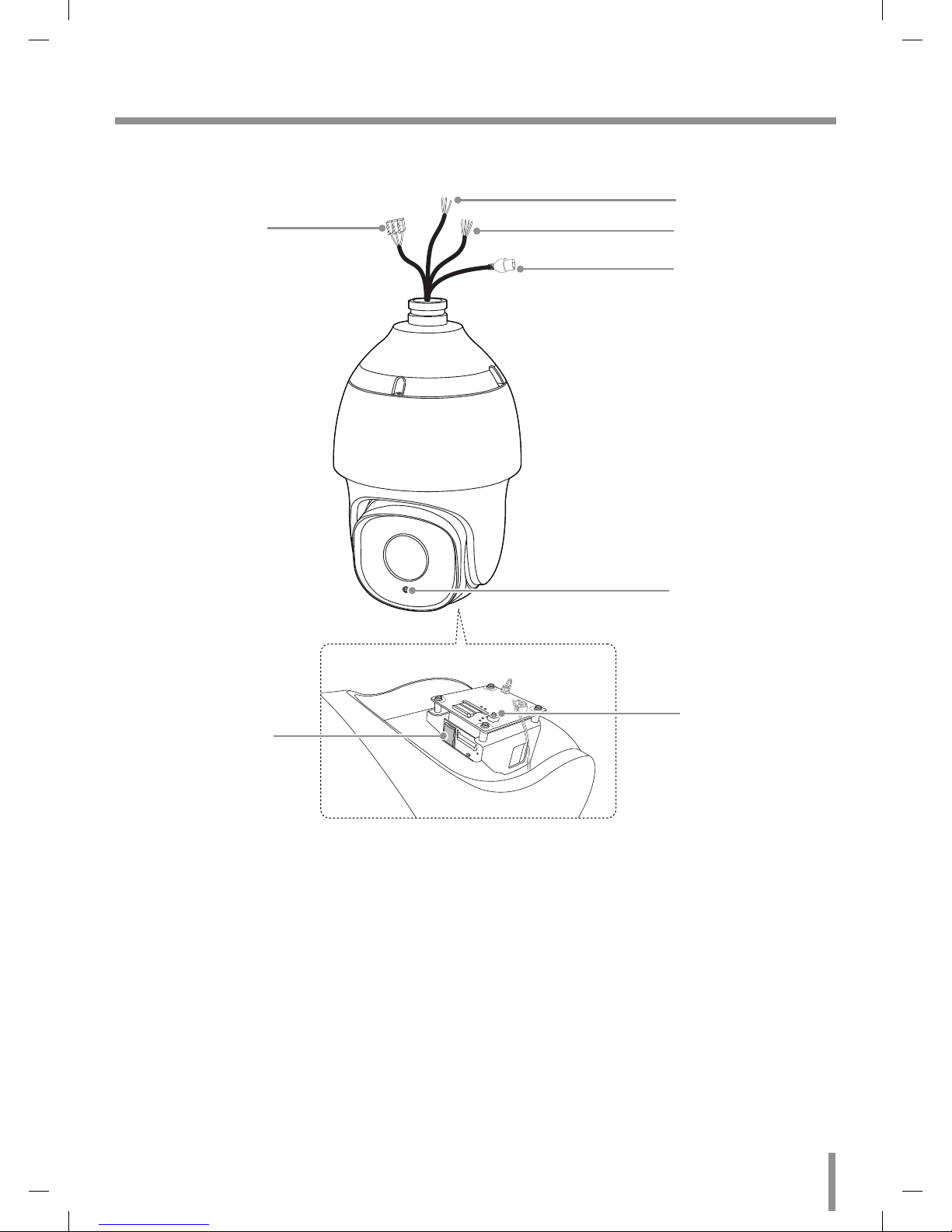
Part Names and Functions
a Lens Cap
b Lens iris output connector (LENS)
This 4- pin connector is used to send the Iris control signal and power
supply to an auto-iris type lens.
c Camera installation hole
d PWR (Power indicator)
Lights when the camera is powered.
e ABF
ABF ( AUTO Back Focus ) is an adjustable function of the back focus
automatically.
f Power input terminal
Connects to DC 12 V or AC 24 V power supply using proper cables.
This camera must always be operated DC 12 V or AC 24 V. Certified/
Listed Adaptor which comply with LPS.
g ETHERNET/PoE Port
Connects to a PC or a network via a hub with a 10 BASE-T/100
BASE-TX cable attached RJ-45 connector.
Note:
Power over Ethernet (PoE) is a technology that integrates power
into a standard LAN infrastructure. It enables power to be provided
to the network device, such as a network camera, using the same
cable as that used for network connection. It eliminates the need for
power outlets at the device locations and enables easier application
of uninterruptible power supplies (LPS).
h SD card slot
i AUDIO IN
Input for a mono microphone, or a line-in mono signal.
j AUDIO OUT
Connecttoanactivespeakerwithabuilt-inamplier.
k External device connectors
• ALARM OUT (1A/1B) Terminals: Provides physical interface for
Alarm/Relay.
• ALARM IN (1/2) Terminals: Provides physical interface for sensor.
• ALARM IN (3) Terminals: External Day/Night fucntion is supported
as using ALARM IN.
• RS232 (RX/TX): RS232 is not used (Only for technical specialist).
• RS-485 (A/B): Connect an external PTZ device.
l VIDEO OUT
Connect the video signal between the IP camera and the monitor.
m RST (RESET button)
Push the button more than 5 seconds, this would restore the factory
default network related settings.
a
c
h
f
g
k
i j
l
m
de
b
Installation 5
Connection
Precautions
• Be sure to switch off the unit before installation and connection.
• The installation should be made by qualified service personnel or
system installers.
• Do not expose the power and connection cables to moisture, which
may cause damage to the unit.
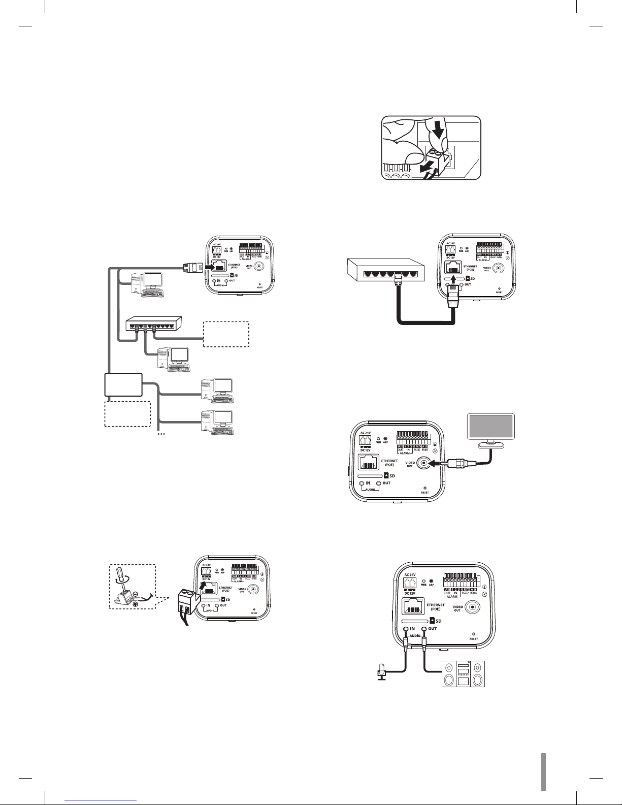
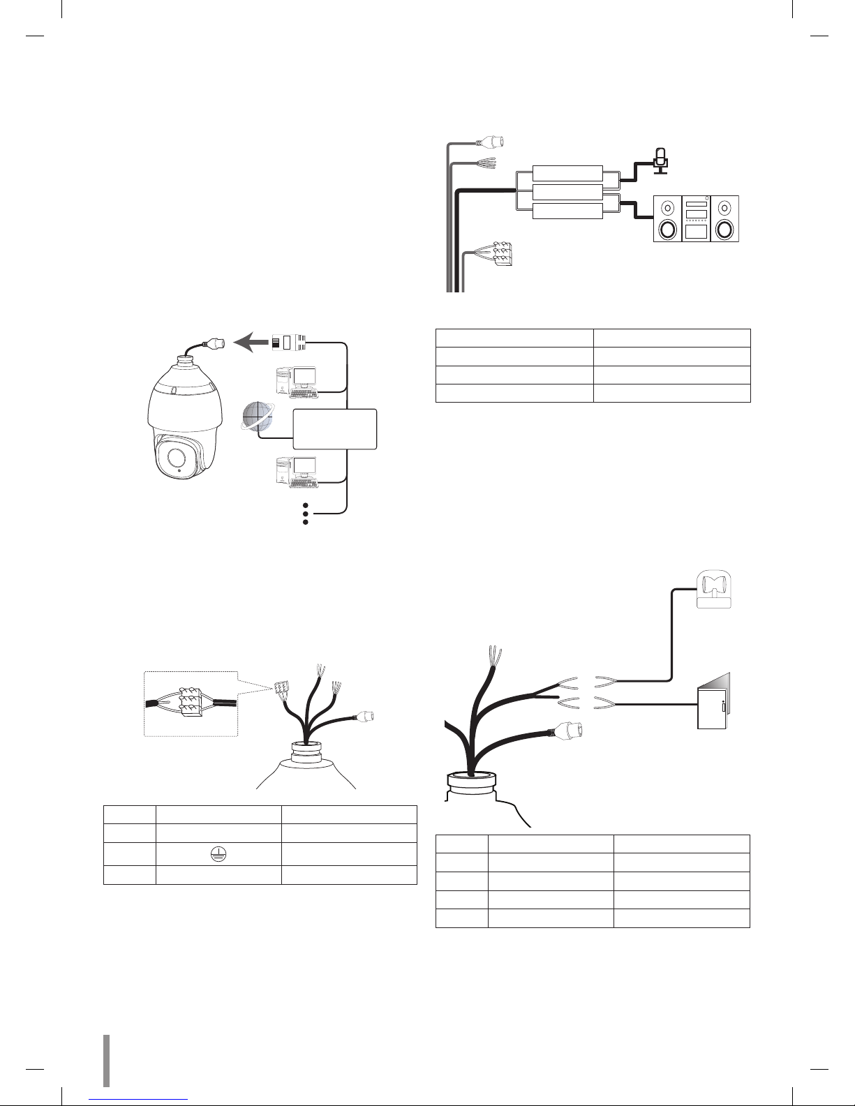
Connecting Network
You can control and monitor the system via network. With the remote
control (monitoring), you can change the system configuration or monitor
the image via network. After the installation, check the network settings
for the remote control and monitoring work.
Connect the IP camera to your network using a standard RJ-45 network
cable as shown below.
Broadband
Service
Broadband
Service
Router
PoE Device
(IEEE802.3af)
Connecting Power Source
Connect power, using one of the methods listed below:
To use the power adapter
Connect DC 12 V or AC 24 V power source to the power input terminal
as shown below. (recommended power adapter is DC 12 V or AC 24 V /
1.5 A or above).
Connect a power source to the power input terminal with 2 and 3
aligned correctly as shown below.
Note:
• When connecting the power, tighten the screws as shown above.
• To remove the connector plug, as shown below. Put your finger
between the power connector and the camera body to pull out the
connector.
POWER
1 2 3
+
-
To use the PoE (Power over Ethernet) device
Connect the PoE cable to the LAN port on the unit. You must use the
“IEEE802.3af” standard PoE device.
PoE Device
(IEEE802.3af)
Note:
If the camera doesn’t work properly after connecting PoE device, please
check if the PoE device supplies enough power.
Connecting Display Device
Connect the video signal between the IP camera and the monitor.
Connecting Microphone and Speaker Device
Optionally connect an active speaker and/or external microphone with a
built-in amplifier.
AUDIO IN
AUDIO OUT
Note:
Keep the microphone away from the speaker to avoid howling.
6 Installation
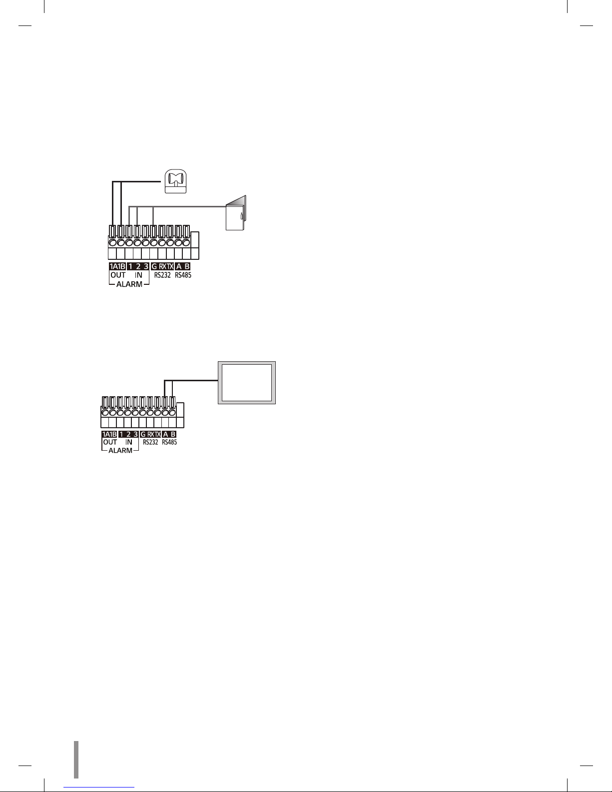
Connecting Alarm Device
Alarm terminals are used to connect the alarm (relay) devices such as
sensors, door switches, etc.
ALARM IN & OUT / ALARM IN & OUT Ret (Sensor Input / Relay
Output)
Connect the sensor device to the sensor input terminal and ground
(GND) terminal. Use the ground (GND) terminal when you need to
connect the sensor device.
Connect the alarm (relay) device to the relay output terminal. Alarm
signal is outputted at an event occurrence.
Alarm (relay)
Device
Sensor
Device
Connecting PTZ Device
You can control the Pan, Tilt, Zoom, Focus and Preset when the PTZ
device is connected.
PTZ
Device

Installation 7
Using the SD card
You can record your surveillance environment with the SD card even if the
network is disconnected condition.
To insert the SD card
Insert the SD card carefully as shown in the following
illustrations. Make sure the SD card terminal position before insert the SD
card. Push the back end of the SD card to fix it at the last step.
Note:
• Do not use the power too much when you insert the SD card. The SD
card may be damaged.
• If you insert the SD card in the wrong position, the SD card may be
damaged or it may cause the malfunction of the SD card Slot.
• Keep the terminal part of the SD card in clean. Be careful the terminal
part of the SD card not to dusty.
• As the SD card is consumable, the SD card end its days and may be
not able to save data if you use it more than over certain times. In
this case, replace SD card to buy a new one.
Remove the SD card
1. Press the back end of the SD card to release the lock condition.
2. Take the SD card out carefully from the camera. It may cause a
malfunction of the SD card or the SD card slot if you use the power
too much at lock status.
Note:
• If you want to initialize the memory disks, install the SD card
and operate [Initialize Disk] function. ( [configuration > storage
Management > Disk Management > Initialize Disk] ). When you
operate [Initialize Disk], camera will reboot.
• LG Innotek is not responsible for deleted data caused by user
mishandling when you insert or remove the SD card.
Recommended the SD card specication
Maker Capacity File System
Sandisk
From 8 GB to 128 GB EXT3
Transcend
Note:
Speed of reading and writing more than 10 MB/Sec. (Class 6)
8 Installation
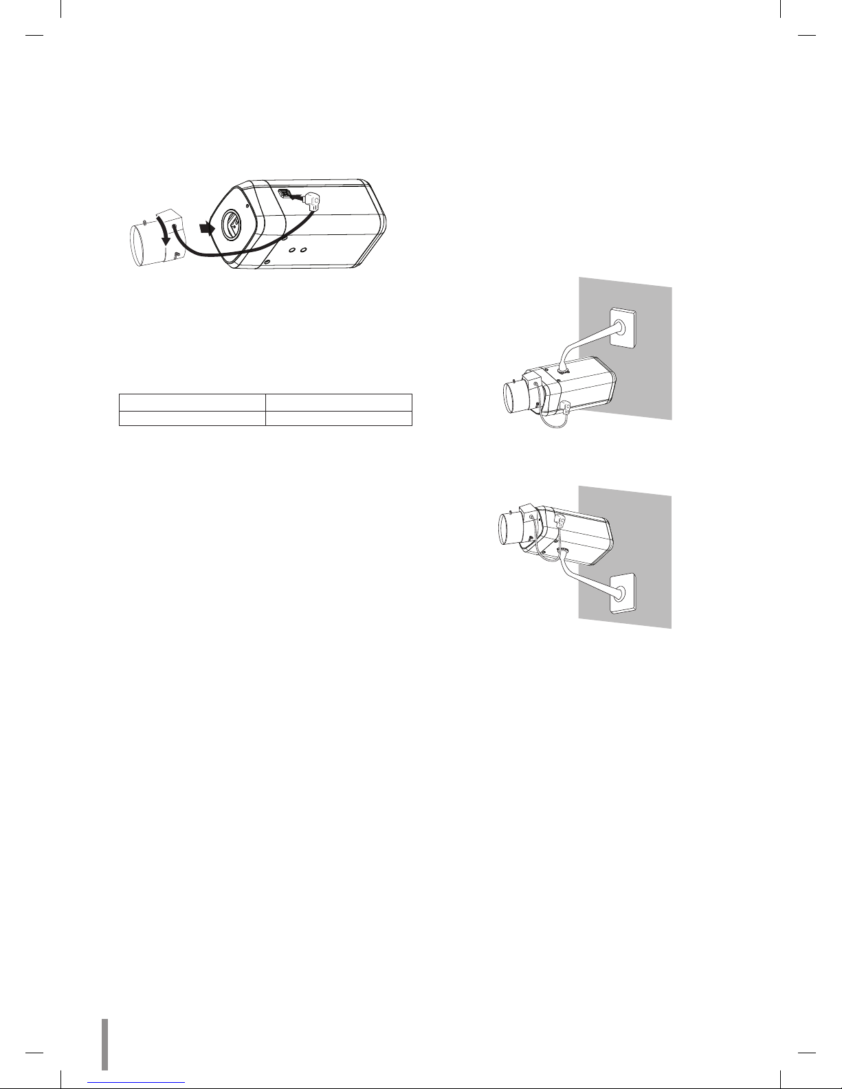
Mounting the Lens
1. Remove the lens mount cap from the camera.
2. Install the CS mount type lens. Carefully align the lens mount with
the camera opening, then turn the lens slowly to install it. The proper
installation is that you face each flat (non-hood) side toward the
corner.
3. Connect the lens plug to the lens iris output connector (LENS) on the
side of the camera. When using lenses from other makers, the plug
shape may not correspond to the terminal on the camera. In such a
case, remove the original plug and using a soldering iron, connect a
lens iris plug according to the diagram.
Note:
• Recommended DC-Iris Lens
Maker Model name
FUJINON DV4x12.5SR4A-SA1L
• We recommend using Lens of 2.0 Mega Pixel or above.
Focus adjustment
After installing the lens, you should adjust the focus as shown below
steps.
1. Keep pressing ABF button about 4 seconds.
2. Adjust approximate zoom and focus level of the lens manually.
3. Press ABF button to adjust the focus automatically.
Camera Installation
Select a location that is strong enough to bear the full weight and install
the camera securely.
Installation 9
Installation (RNZE-B501A)
Part Names and Functions
a Power input terminal
Connects to AC 24 V power supply using proper cables. This camera
must always be operated AC 24 V. Certified/Listed Adaptor which
comply with LPS.
b External device connectors
• AUDIO IN: Input for a mono microphone, or a line-in mono signal.
• AUDIOOUT:Connecttoanactivespeakerwithabuilt-inamplier.
• GND : Common port
c ALARM IN & OUT / ALARM IN & OUT Ret
• ALARM IN: Provides physical interface for sensor.
External Day/Night function is supported as using ALARM IN.
• ALARM OUT: Provides physical interface for Alarm/Relay.
• ALARM GND: Ground port for alarm input.
d ETHERNET
Connects to a PC or a network via a hub with a 10/100 BASE-T
cable attached RJ-45 connector.
e IR Sensor
f micro SD card slot
Insert the micro SD card.
g RESET button
Push the button more than 5 seconds, this would restore the factory
default network related settings.
a
b
c
d
e
f
g
10 Installation
Connection
Precautions
• Be sure to switch off the unit before installation and connection.
• The installation should be made by qualified service personnel or
system installers.
• Do not expose the power and connection cables to moisture, which
may cause damage to the unit.
Connecting Network
You can control and monitor the system via network. With the remote
control (monitoring), you can change the system configuration or monitor
the image via network. After the installation, check the network settings
for the remote control and monitoring work.
Connect the IP camera to your network using a standard RJ-45 network
cable as shown below.
Broadband
Service
Connecting Power Source
Connect power, using one of the methods listed below:
To use the power adapter
Connect AC 24 V power source to the power input terminal as shown
below. (recommended power adapter is AC 24 V / 3 A or above).
A
B
C
No. Description Color
A
AC 24 V 1 RED
B
YELLOW GREEN
C
AC 24 V 2 GREEN
Connecting Microphone and Speaker Device
Optionally connect an active speaker and/or external microphone with
a built-in amplifier.
AUDIO IN
GND
AUDIO OUT
Note:
Keep the microphone away from the speaker to avoid howling.
Color Description
PURPLE AUDIO IN
BROWN AUDIO OUT
GREEN GND
Connecting Alarm Device
Alarm terminals are used to connect the alarm (relay) devices such as
sensors, door switches, etc.
ALARM IN & OUT / ALARM IN & OUT Ret
Connect the sensor device to the sensor input terminal and ground
(GND) terminal. Use the ground (GND) terminal when you need to
connect the sensor device.
Connect the alarm (relay) device to the relay output terminal. Alarm
signal is outputted at an event occurrence.
A
B
C
D
Sensor
Device
ALARM IN
ALARM OUT
Alarm (relay)
Device
No. Description Color
A
ALARM IN 1 RED
B
ALARM GND BLUE
C
ALARM OUT 1 WHITE BROWN
D
ALARM OUT COM WHITE BLUE
Installation 11
Using the micro SD card
You can record your surveillance environment with the micro SD card
even if the network is disconnected condition.
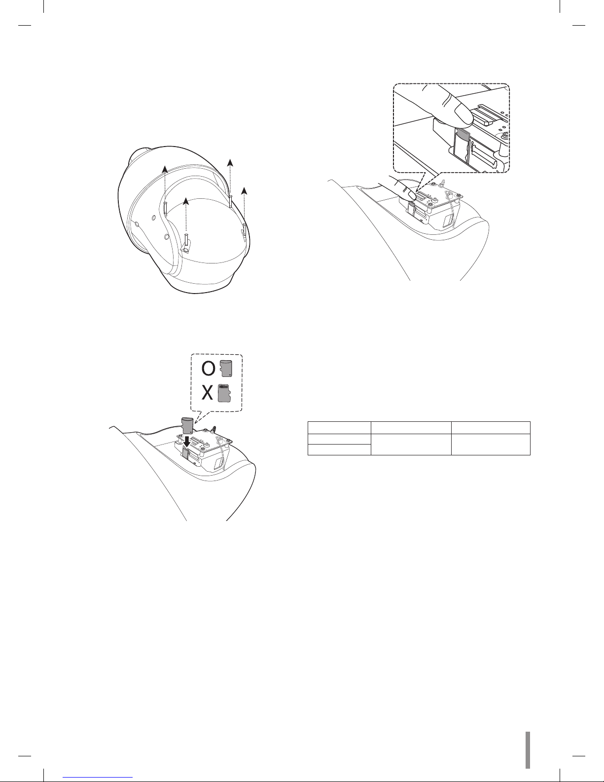
To insert the micro SD card
1. Remove the cover as show below.
2. Insert the micro SD card carefully as shown in the following
illustrations. Make sure the micro SD card terminal position before
insert the micro SD card. Push the back end of the micro SD card to
fix it at the last step.
Note:
• Do not use the power too much when you insert the micro SD
card. The micro SD card may be damaged.
• If you insert the micro SD card in the wrong position, the micro
SD card may be damaged or it may cause the malfunction of the
micro SD Card Slot.
• Keep the terminal part of the micro SD card in clean. Be careful
the terminal part of the micro SD card not to dusty.
• As the micro SD card is consumable, the micro SD card end its
days and may be not able to save data if you use it more than
over certain times. In this case, replace micro SD card to buy a
new one.
Remove the micro SD card
1. Press the back end of the micro SD card to release the lock condition.
2. Take the micro SD card out carefully from the camera. It may cause a
malfunction of the micro SD card or the micro SD card slot if you use
the power too much at lock status.
Note:
• If you want to initialize the memory disks, install the micro SD
card and operate [Initialize Disk] function. ( [configuration >
storage Management > Disk Management > Initialize Disk] ).
When you operate [Initialize Disk], camera will reboot.
• LG Innotek is not responsible for deleted data caused by user
mishandling when you insert or remove the micro SD card.
Recommended the micro SD card specication
Maker Capacity File System
Sandisk
From 8 GB to 128 GB EXT3
Transcend
Note:
Speed of reading and writing more than 10 MB/Sec. (Class 6)
12 Installation
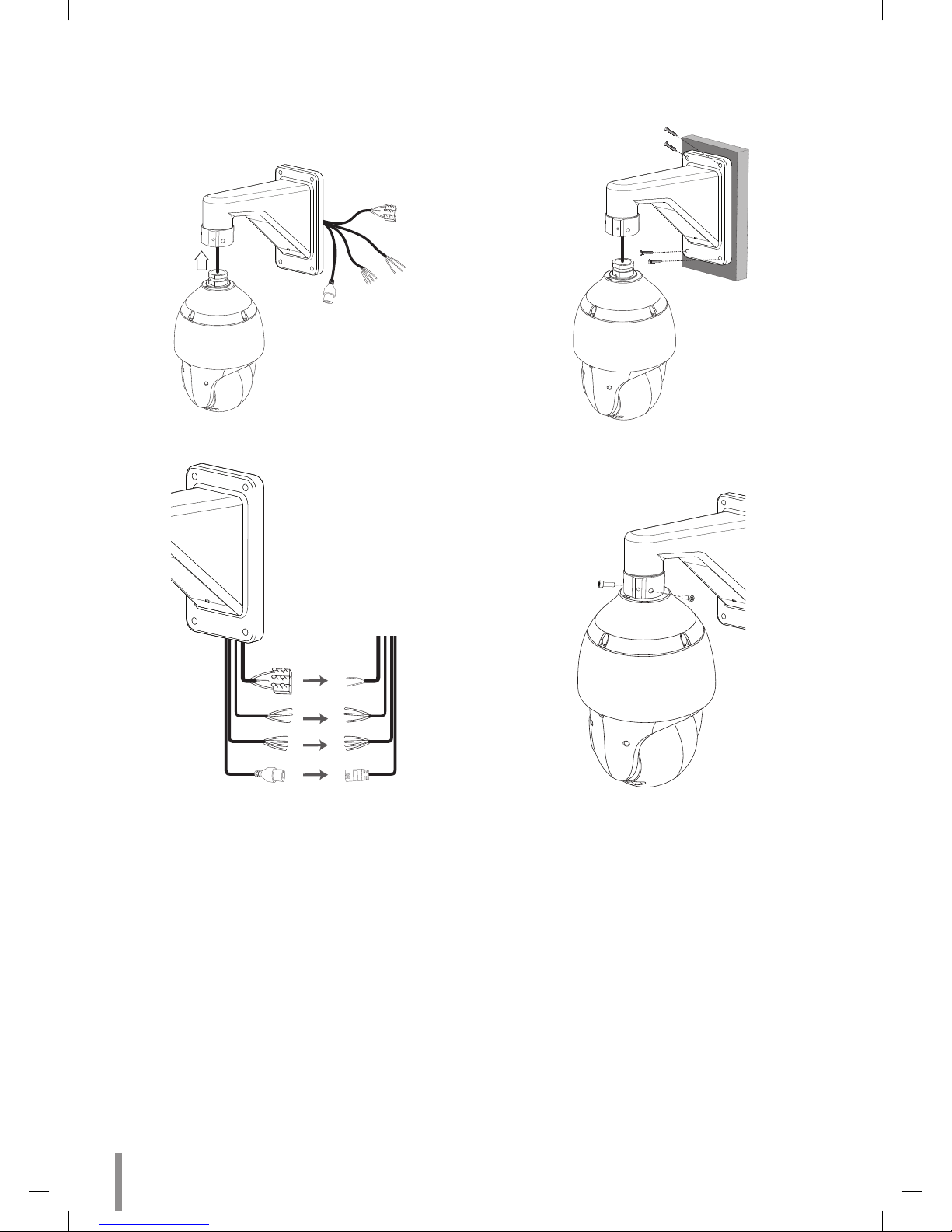
Wall mount (optional)
Install the camera by the following order.
1. Pass the connection cable through the wall mount assembly.
2. Make cable connections.
3. Drill holes on the wall where you want to install the wall mount
assembly and fasten screws to fix it.
4. Fasten the screws as shown below to fix the camera to the wall
mount assembly.

Operation and settings 13
Before using the system
• LG IP device recommended to use in the closed network for network
security.
• Before using the LG IP device make sure the connections are correct
and verify whether proper power supply is used.
• Check the connections of the LG IP device for the correct conditions.
• Check that the LG IP device is connected to the network and that
power is supplied.
• Once the connections are made you need to install the LG client
program to the PC from which you want to access the device.
The LG Smart Web Viewer program is automatically installed when
you connect the LG IP device.
The LVi510 and the LG Smart Web Viewer program are the network
program of the LG Video Server and the LG IP cameras.
• To view streaming video in Internet Explorer, set your browser
to allow ActiveX controls. If you find this message “Click here to
download the plug in, close all explorers during the installaion.”, Click
the blue bar and install LG Smart Web Viewer Program on your
computer. Please set your browser zoom level to 100%.
• The Layouts and the Live view pages may differ with different OS
(Operating Systems) and Web Browsers.
• Care needs to be taken not to run any other applications when the
Client Program is running as it may cause memory shortage.
• When you set on 60 fps in mobile applications, may be degraded the
frame rate depending on mobile performance.
Recommended PC Requirements
The LG IP device can be used with most standard operating systems and
browsers.
Items Requirements
Operating System
Windows XP Professional,
Windows 7 or above
CPU Intel i7 or above
Web Browser IE9 or above
DirectX 10.X or above
Memory 4 GB or above
Graphics Card 512 MB or above
Hard Disk 250 GB or above
Resolution 1920 x 1280 or above
Note:
For Windows 7, please download & install ‘DirectX End-User Runtime
Web Installer’.
http://www.microsoft.com/en-us/download/details.aspx?id=35
Operation and settings
14 Operation and settings
Accessing the LG IP device
You can access the LG IP device by following the below steps.
1. Install LVi510 Program
It is recommended to use LVi510 surely.
Otherwise, it is required to install the IP Utility
[Package>Tools>LG IP Utility Installer] to search the IP addresses
of LG IP devices.
2. Discover the LG IP device using the IP Utility
The IP Utility can automatically discover and display LG IP devices on
your network.
The IP Utility shows the MAC address, IP address, Model name and
so on.
Note:
The computer running the IP Utility must be on the same network
segment (physical subnet) as the LG IP device.
2.1 Run the IP Utility program.
2.2 Click the [Search] button or select the [Search] option in the
Device search menu.
After a few seconds the found LG IP devices gets displayed in
the IP Utility window.
3. Logging in to the LG Smart Web Viewer
3.1 Run the IP Utility and find the LG IP devices.
3.2 When the LG IP devices appear in the IP Utility window,
double-click IP address or right click on the same IP address
and select “Connect to Web Page” to start the LG Smart Web
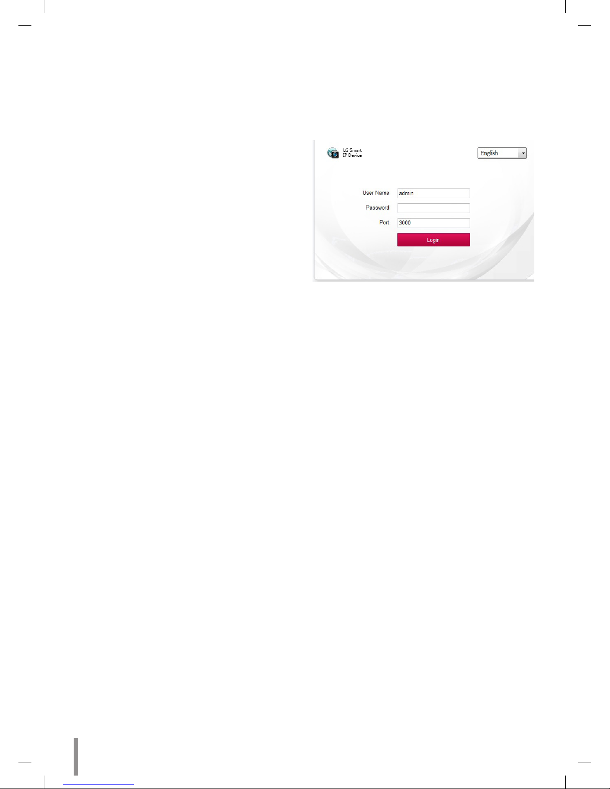
Viewer. When accessing the LG Smart Web Viewer, the window
for login will be shown. Select the language in drop-down list
on right top of the window.
3.3 Enter the user name and password. (Note that the default
administrator user name and password are “admin”.)
Note:
Default password must be changed for security after initial
connection.
Note:
• You can also access the LG Smart Web Viewer as shown
below.
3.1 Start your Web browser.
3.2 Enter the IP address of the LG IP device in the address
bar of the browse.
3.3 Enter the user name and password set by the
administrator.
• Check the browser cookies settings to use the
[Remember my credentials].
• If LG Smart Web Viewer is required to be updated, it needs
more time to display according to the network conditions.
• If you connect the LG Smart Web Viewer for the first time,
the Security Warning window is displayed to install the LG
Smart Web Viewer program. You must install the LG Smart
Web Viewer program for using the LG IP device.
• If your computer or network is protected by a proxy or
firewall, the proxy or firewall settings can prevent the LG
Smart Web Viewer program. Change the proxy or firewall
settings to activate the LG Smart Web Viewer program.
• Please use IE browser of windows and make sure the version
above 9.0. Do not use any other browser except Firefox,
Google.

Operation and settings 15
LG Smart Web Viewer Overview
Live View
Item Description
Preview the first stream video (Default display).
Note:
You can set the stream configurations independently. This would facilitate the user to set the live view at user’s comfort.
Previews the second stream video.
Previews the third stream video.
Original Aspect Ratio
Fixed proportion of video images according to the resolution of the IPC.
Fit window
Displays video images to fit windows.
Local record
Click this button, video is recorded automatically. To stop the recording, click this button again during the recording.
Default save path is:
D:\NetVideoBrowser\ RecordFiles
Snapshot
Click this button, current image is saved automatically to JPEG format on your computer.
Default save path is:
D:\NetVideoBrowser\ CapturePics
Talkback
Click this button to start intercom. To stop intercom, click this button again.
 Loading...