

Page 1
Please read this manual carefully before operating
your set.
Retain it for future reference.
Record model number and serial number of the set.
See the label attached on the bottom of the set and
quote this information to your dealer when you
require service.
Model number :
Serial number :
RL-JA20
OWNER’S MANUAL
LG LCD PROJECTORLG LCD PROJECTOR
R
Page 2
LCD PROJECTOR
R
LCD PROJECTOR
Warning
This is a class B product. In a domestic environment this product may cause radio
interference, in which case the user may be required to take adequate measures.
FCC NOTICE
• A Class B digital device
This equipment has been tested and found to comply with the limits for a Class B digital
device, pursuant to Part 15 of the FCC Rules. These limits are designed to provide
reasonable protection against harmful interference in a residential installation.
This equipment generates, uses and can radiate radio frequency energy and, if not
installed and used in accordance with the instructions, may cause harmful interference
to radio communications. However, there is no guarantee that interference will not occur
in a particular installation. If this equipment does cause harmful interference to radio or
television reception, which can be determined by turning the equipment off and on,
the user is encouraged to try to correct the interference by one or more of the
following measures:
- Reorient or relocate the receiving antenna.
- Increase the separation between the equipment and receiver.
- Connect the equipment into an outlet on a circuit different from that to which the
receiver is connected.
- Consult the dealer or an experienced radio/TV technician for help.
• Any changes or modifications not expressly approved by the party responsible for
compliance could void the user’s authority to operate the equipment.
Page 3

After reading this
manual please keep
it in a safe place for
future reference.
CONTENTS
INTRODUCTION
Safety Instructions..................................................................4
Names of parts.....................................................................12
INSTALLATION AND COMPOSITION
Installation Instructions.........................................................18
Composition..........................................................................20
Turning on the Projector .......................................................22
Turning off the Projector .......................................................23
Operating the Projector ........................................................24
Selecting source mode.........................................................25
CONNECTION
Connecting to a Desktop PC................................................26
Connecting to a Notebook PC..............................................27
Connecting to a Macintosh Desktop PC ..............................28
Connecting to a Macintosh PowerBook ...............................31
Connecting to a wireless transmitter (option) .......................32
Connecting to a wireless receiver (option)...........................33
Connecting to a Video Source..............................................34
Connecting to a DVD............................................................35
Connecting to a D-TV Set-Top Box......................................36
BASIC FUNCTIONS
Function checking.................................................................37
Using Still function................................................................38
SPECIAL FUNCTIONS
Selecting language...............................................................39
Checking lamp time..............................................................40
Manual Color Temperature Control......................................41
Using Blank function.............................................................42
Using Flip Horizontal / Vertical function................................44
Twin Picture function............................................................46
POSITIONING
Adjusting screen display.......................................................48
Using Keystone function.......................................................49
Using Zoom function.............................................................50
Using ARC function..............................................................51
VIDEO
Adjusting Video.....................................................................52
TRACKING
Using Tracking function........................................................54
RS-232C
External control device setup...............................................56
INFORMATION
Supported Monitor Display...................................................63
Maintenance.........................................................................64
Memo....................................................................................65
Specifications ......................................................................67
Page 4
Safety Instructions
GG Please take note of the safety instructions to prevent any potential accident or misuse of the projector.
GG Safety Instructions are given in two forms as detailed below.
WARNING
NOTES
GG After reading this manual, keep it in the place that the user always can contact easily.
The violation of this instruction may cause serious injuries and even death.
The violation of this instruction may cause light injuries or damage to the projector.
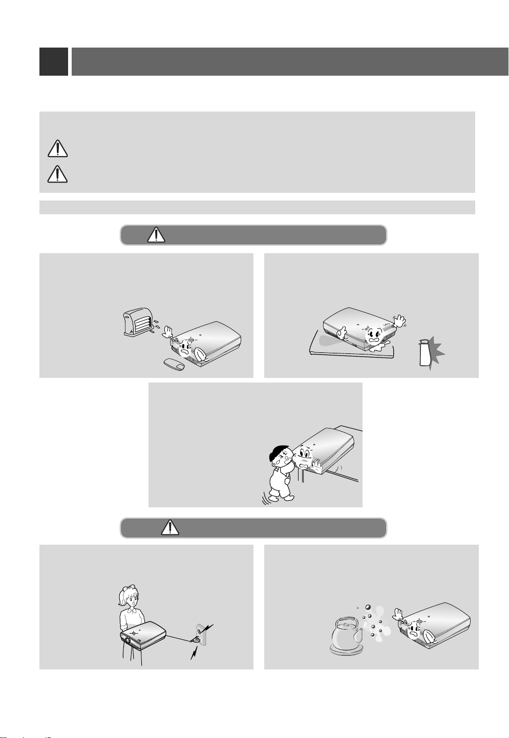
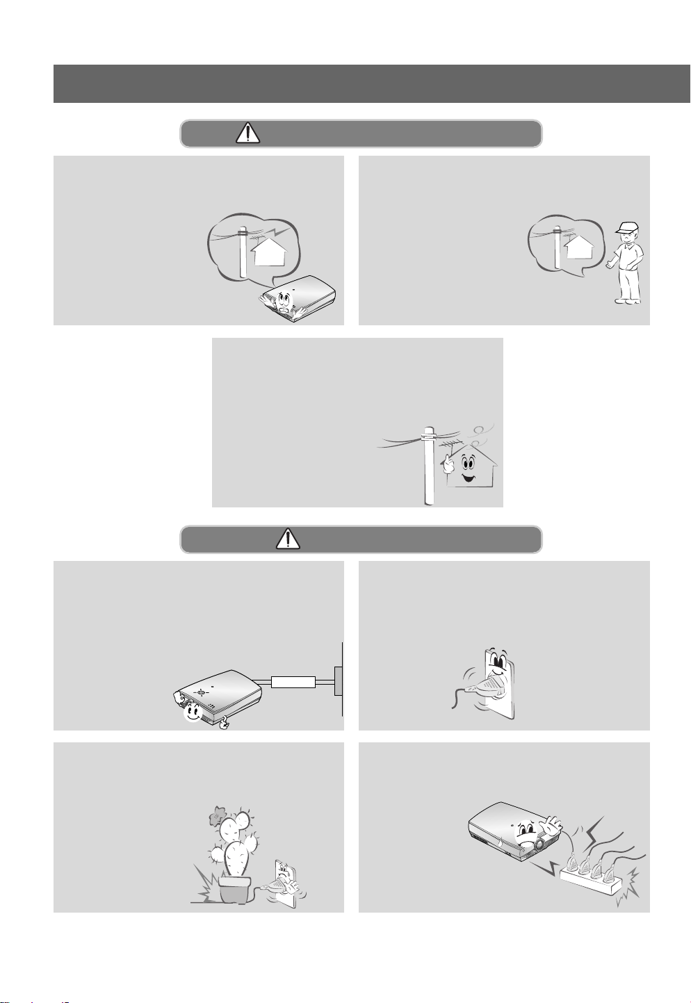
Indoor Installation-WARNING
Do not place the Projector in direct sunlight or
near heat sources such as radiators, fires and
stove etc.
- This may cause
a fire hazard !
R
Do not allow children to hang on the
installed projector.
- It may cause the projector to fall, causing
injury or death.
Do not place inflammable materials
beside the projector
- This may cause a fire hazard !
R
Indoor Installation-NOTES
Disconnect from the mains and remove all
connections before moving.
R
4
R
Do not place the projector close to sources
of steam or oil such as a humidifier.
- This may create a fire hazard or an
electric shock
hazard !
R
Page 5
Indoor Installation-NOTES
R
INTRODUCTION
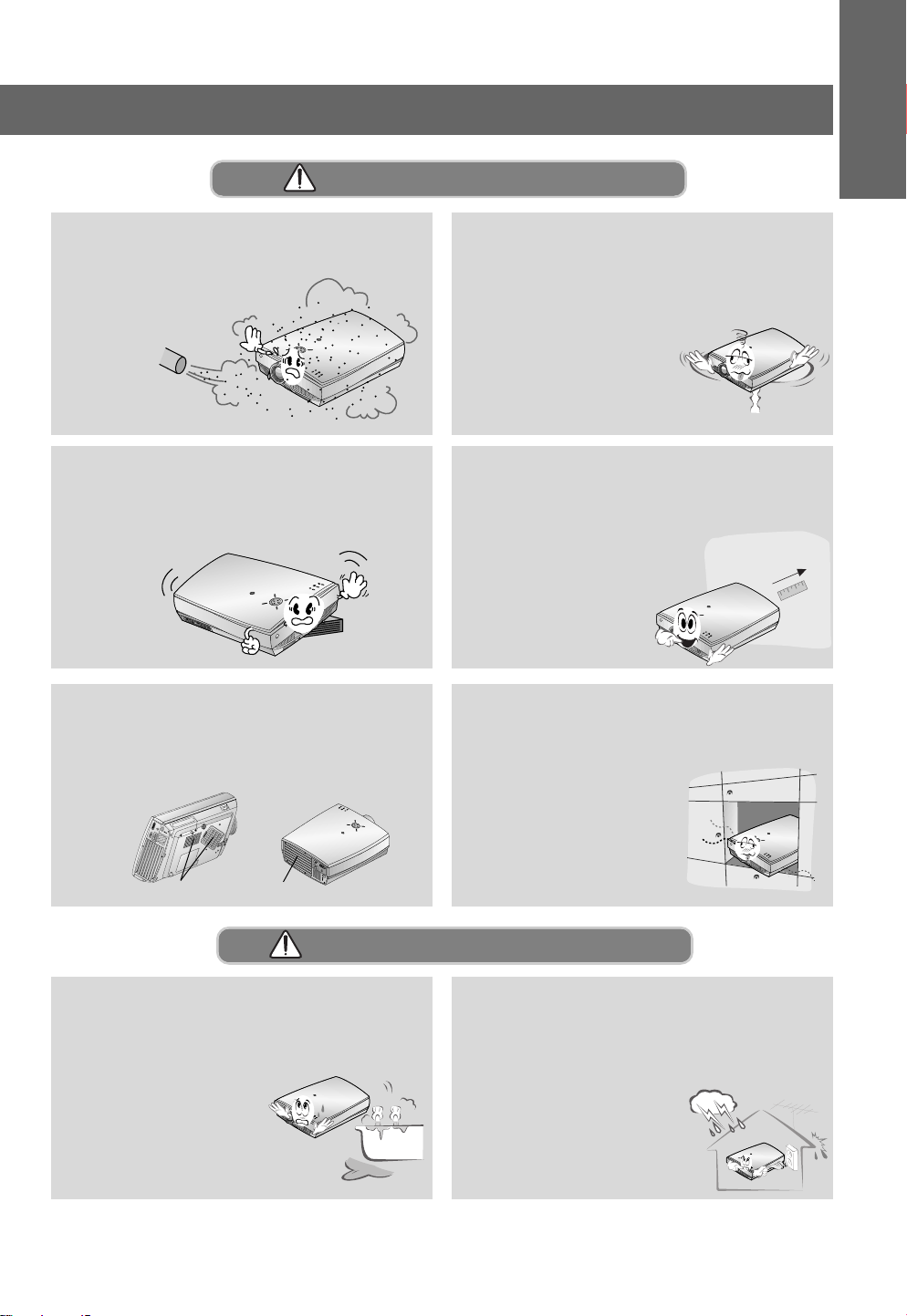
Do not place the projector where it might
be exposed to dust.
- This may cause a fire hazard !
R
Only use the projector on a level and stable surface.
- It may become unstable and affect operation.
R
Do not block the vents(air intake/exhaust) of
the projector or restrict air-flow in any way.
- This would cause the internal temperature to
increase and could cause a fire hazard!
KK
When installing the projector on a table, be
careful not to place it near the edge.
- This may cause the projector to fall
causing serious injury to a child
or adult and serious damage
to the projector.
R
- Only use a suitable stand.
Ensure good ventilation around the projector. The distance between the projector
and the wall should be more
than 30cm.
- An excessive increase
in its internal
temperature may
R
cause a fire hazard!
Do not place the projector directly on a
carpet, rug or place where ventilation is
restricted.
- This would cause its
internal temperature to
increase and might
create a fire hazard !
K
Air intake
exhaust pipe
Outdoor Installation-WARNING
Do not use the projector in a damp place
such as a bathroom where it is likely to get
wet.
- This may cause a fire or an
electric shock hazard !
R
In case of using a receiver (VCR, Digital
Set Top Box), bend antenna cable
between inside and outside building to
prevent rain from flowing in.
- This may cause water
damaged inside the
projector and could
give an electric shock.
R
5
Page 6
Safety Instructions
Outdoor Installation-NOTES
In case of using a receiver (VCR, Digital
Set Top Box), do not place an antenna in
the vicinity of power
lines.
- This may cause an
electric shock.
R
In case of using a receiver (VCR, Digital
Set Top Box), there should be enough distance between an outside antenna and
power lines to keep the former from
touching the latter even when
the antenna falls.
- This may cause an electric shock.
Power-WARNING
Earth wire should be connected.
- If the earth wire is not connected, there is possible a
danger of electric shock caused by the current leakage.
- If grounding methods are not possible, a separate cir-
cuit breaker should be employed and installed by a
qualified electrician.
- Do not connect ground
to telephone wires,
lightning rods or
gas pipe.
R
Short-circuit
Power
breaker
If connecting a receiver (VCR, Digital Set
Top Box), contact your service centre to
erect an antenna as this
work should be carried
out by skilled personnel.
- This may cause an
electric shock.
The mains plug should be inserted fully
into the power outlet to avoid a fire
hazard !
- This may cause a fire hazard !
Do not place heavy objects on the power
cord
- This may cause a fire or an electric
shock hazard !
6
Do not use too many plugs on the Mains
multi-outlet.
- It may result in
overheating
of the outlet
and causes a
R
fire hazard !
Page 7
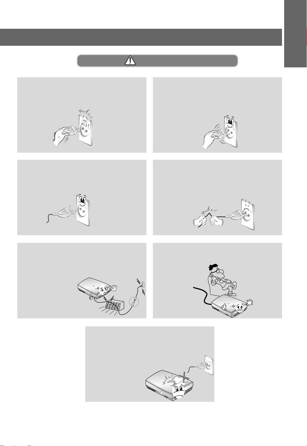
Power-NOTES
INTRODUCTION
Never touch the power plug with a wet
hand
- This may cause an electric shock hazard !
Prevent dust collecting on the power plug
pins or outlet.
- This may cause a fire hazard !
Ensure the power cord does not come
into contact with sharp or hot objects such
as a heater.
- This may cause a fire
or an electric
shock hazard !
R
Hold the plug firmly when unplugging. If
you pull the cord the cord may be damaged.
- This may cause a fire hazard !
Do not plug when the power cord or the
plug is damaged or the connecting part of
the power outlet is loose.
- This may cause a fire or an electric shock
hazard !
Place the projector where people will not
trip or tread on the power lead.
Do not turn the projector On/Off with plugging-in or unplugging the power plug to the
wall outlet.(Do not use the power plug
for switch.)
- It may cause mechanical
failure or could give an
electric shock.
R
R
7
Page 8
Safety Instructions
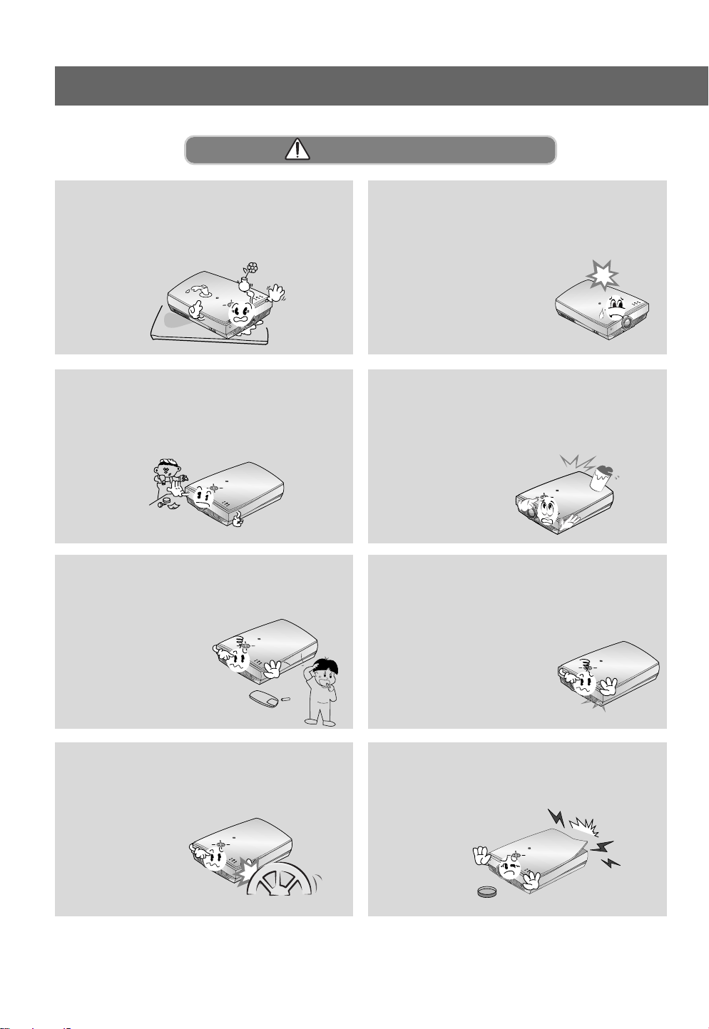
Using-WARNING
Do not place anything containing liquid on
top of the projector such as flowerpot,
cup, cosmetics or candle.
- This may cause a fire hazard !
R
Do not allow any objects to fall into the
projector.
- This may cause an electric shock
hazard !
R
Dispose of used batteries carefully and
safely.
- In the case of a battery being
swallowed by a child
please consult a
doctor immediately.
R
In case of impact shock or damage to the
projector switch it off and unplug it from
the mains outlet and contact your
service center.
- This may cause a fire or an
electric shock hazard !
R
If water is spilt into the projector unplug it
from the mains supply outlet immediately
and consult your Service Agent.
- This may cause an electric
shock hazard !
R
In the event that an image does not
appear on the screen please switch it off
and unplug it from the mains
supply and contact your
Service Agent.
- This may cause a fire or an
electric shock hazard !
R
Do not use the projector in a moving vehicle.
- This may cause an
accident.
R
8
Do not remove any covers (except lens
cover). High risk of Electric Shock!
R
Page 9
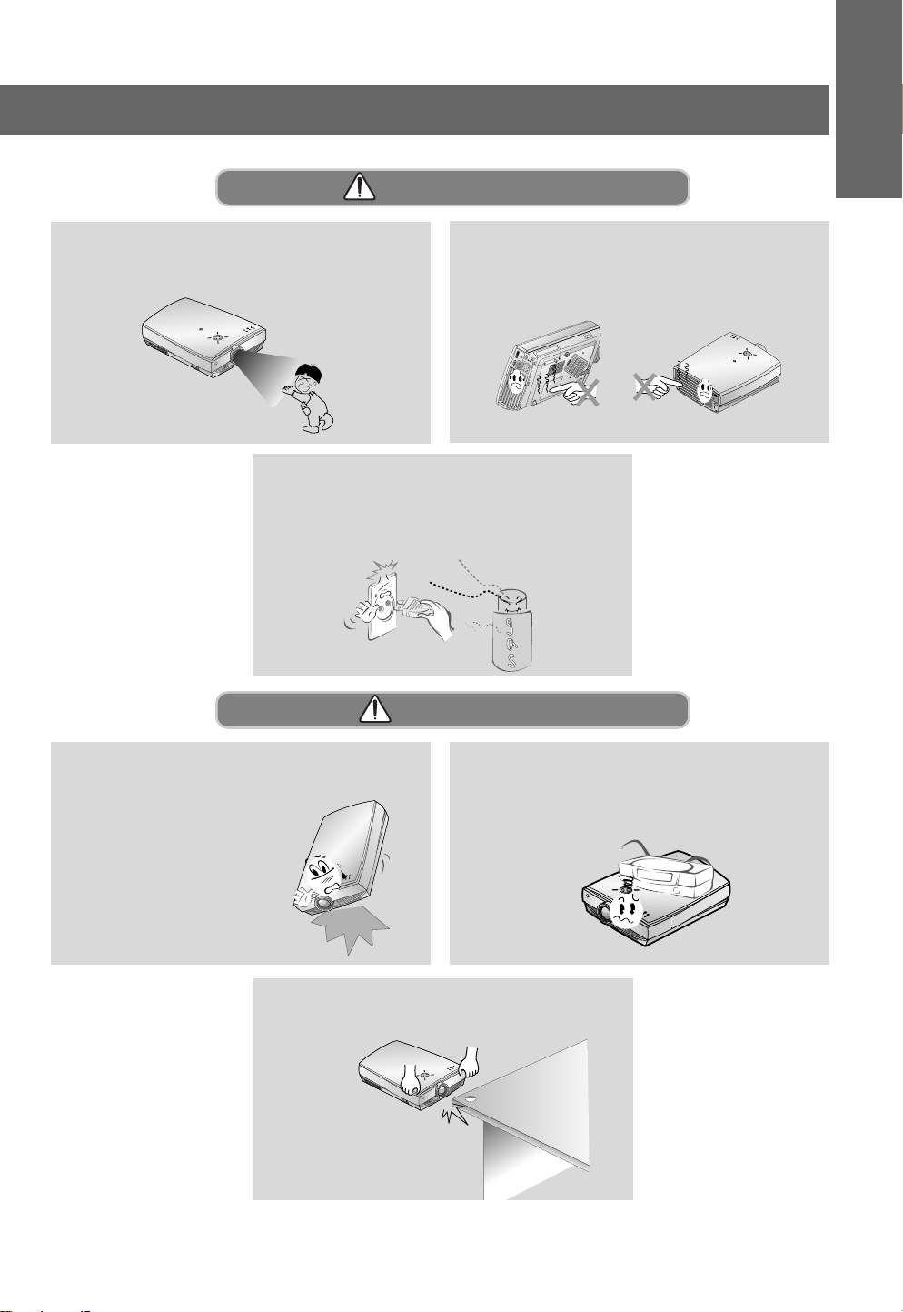
Using-WARNING
INTRODUCTION
Don’t look directly onto the lens when the
projector is in use. Eye damage may occur!
R
Never touch the wall outlet when there is
leakage of gas, open the windows and
ventilate.
- It can cause a fire or a burn by a spark.
Do not drop the projector or allow impact
shock.
- This may cause mechanical
failure or personal injury !
Do not touch metal parts during or soon
after operation since the vents and lamp
cover will remain very hot!
KK
Using-NOTES
Do not place heavy objects on top of projector.
- This may cause mechanical failure or personal
injury!
RGB(DC/DTV )
RS-232C
K
R
R
Take care not to cause impact to the lens
particularly when moving the projector.
R
9
Page 10
Safety Instructions
Using-NOTES
Do not touch the lens of the projector. It is
delicate and easily damaged.
R
Cleaning-WARNING
Do not use water while cleaning the projector
- This may cause damage to the
projector or an electric
shock hazard.
R
Do not use any sharp tools on the projector as this will damage the casing.
R
In the unlikely event of smoke or a
strange smell from the projector,
switch it off , unplug it from the
wall outlet and contact your
dealer or service centre.
- This may cause a fire or
an electric shock hazard !
R
10
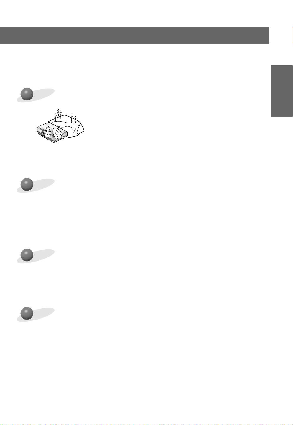
Use an air spray or soft cloth that is moist
with a neutral detergent and water for
removing dust or stains on the projection
lens.
R
Page 11
Cleaning-NOTES
INTRODUCTION
Unplug this product from the wall outlet
before cleaning. Do not use liquid cleaners or aerosol cleaners.
- This may cause damage to
the Projector or cause
an electric shock hazard !
R
Others-WARNING
Do not attempt to service the projector
yourself. Contact your dealer or service
centre.
- This may cause damage to the
projector and could give an
electric Shock as well as
invalidating the
warranty !
RR
Contact the Service Center once a year to
clean the internal parts of the projector.
- Accumulated dust can cause
mechanical failure.
If a receiver (VCR, Digital Set Top Box) is
connected to the projector, in the event of
lightning or thunder storm, unplug the projector and aerial from the wall outlet.
- This will prevent damage to
the projector and possible
electric shock.
Others-NOTES
R
R
Be sure to unplug if the projector is not to
be used for a long period.
Accumulated dust
may cause a fire
hazard!
R
Do not mix new batteries with old batteries.
- This may cause the batteries to overheat and
leak.
Refer lamp servicing to qualified service
personnel.
K
Only use the specified type of battery.
- This could cause damage to the remote
control.
11
Page 12
Names of parts
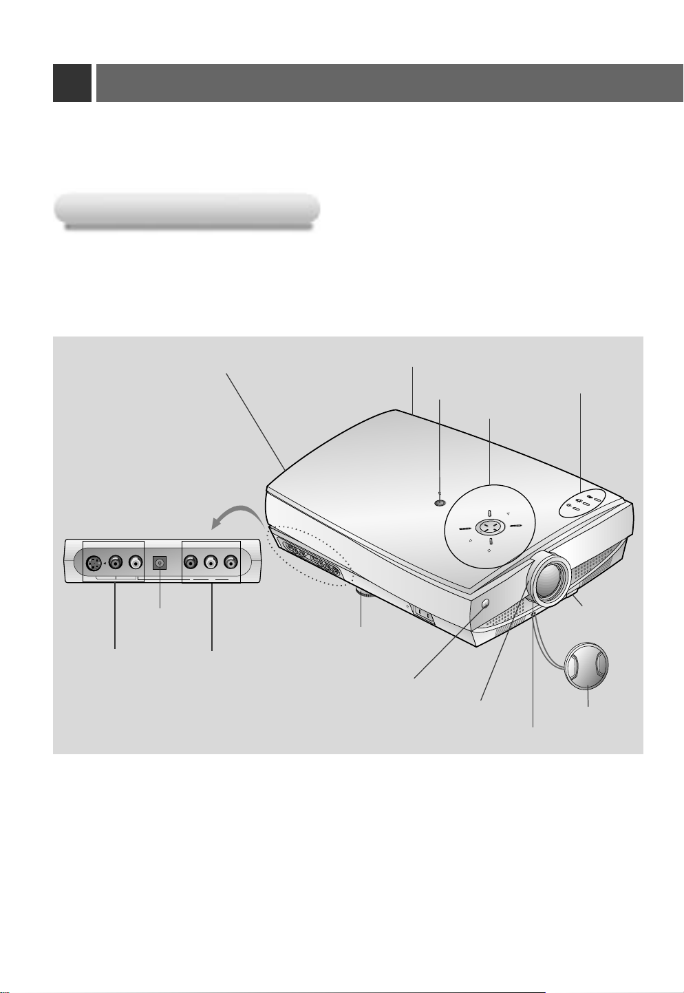
Main Body
Main Body
*
The LCD projector is manufactured using high-precision technology. You may, however, see on the Projector
screen tiny black points and/or bright points (red, blue, or green). This can be a normal result of the
manufacturing process and does not always indicate a malfunction.
S-Video
Video
Audio
DC 12V OUT
DC 12V OUT
S-Video, Video,
Audio
Rear remote control sensor
Component (DVD/DTV)
Y PBP
R
Horizontal leveler
Component(DVD/DTV)
Front remote control sensor
Horizontal leveler
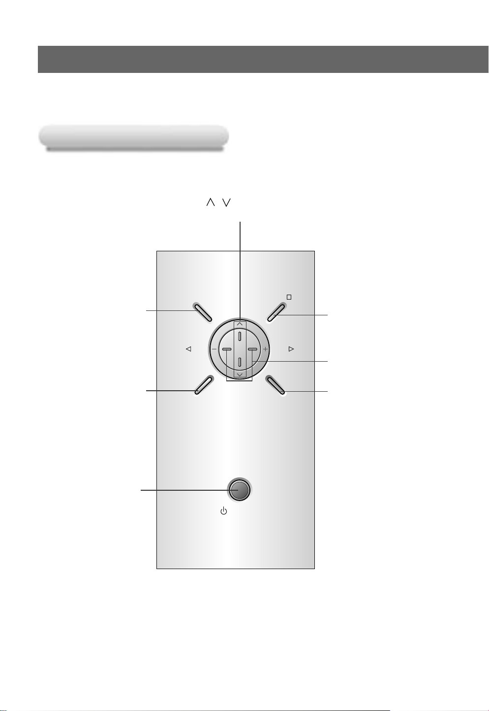
Power button
Control panel
POWER
PATTERN
AC IN
Zoom ring
Indicators
INPUT SELECT
VOL
VOL
R
MENU
OK
/
Foot adjusting
button
Lens cover
Focus ring
12
Page 13
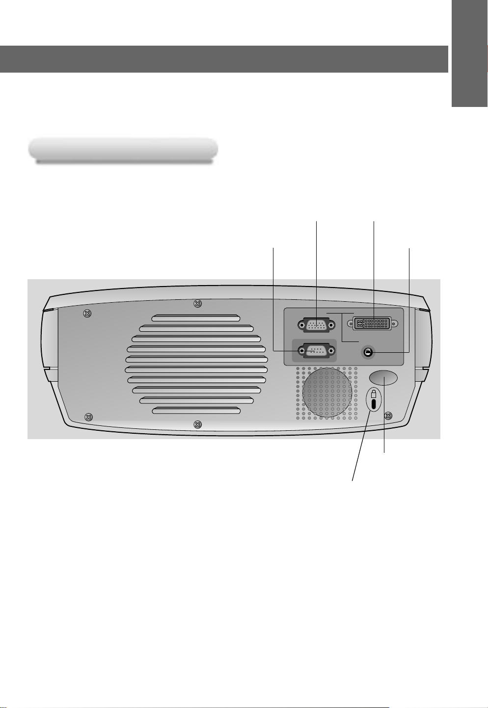
Rear Connecting Part
Rear Connecting Part
INTRODUCTION
A-RGB1 A-RGB2/D-RGB
RS-232C
A-RGB1
RS-232C
A-RGB2/D-RGB
Audio
K
Rear remote
control sensor
Kensington Security
System Connector
(Refer to page 21)
Audio
13
Page 14
Names of parts
INPUT SELECT PATTERN
POWER
VOLVOL
MENU
OK
/
Control Panel
Control Panel
Button
,
Selects menus and items in the menus.
Selects or closes menus.
INPUT SELECT Button
Switches to A-RGB1,
A-RGB2, D-RGB, Video,
S-Video, Component mode.
MENU Button
POWER Button
OK/A Button
Checks present mode and
saves the change of functions.
VOLUME Button
Adjusts volume level and
functions of menus.
PATTERN Button
When pressing the PATTERN
button, the test screen for
focus adjustment is displayed.
14
Page 15
POWER
PICTURE
SWAP
MENU MUTE
OK
VIDEO
COMPONENT
A-RGB1
ZOOM+
ZOOM-
VOLVOL
ARC
AUTO TRACKING
APC
KEYSTONE
SUB INPUT
TWIN
BLANK
STILL
INPUT SELECT
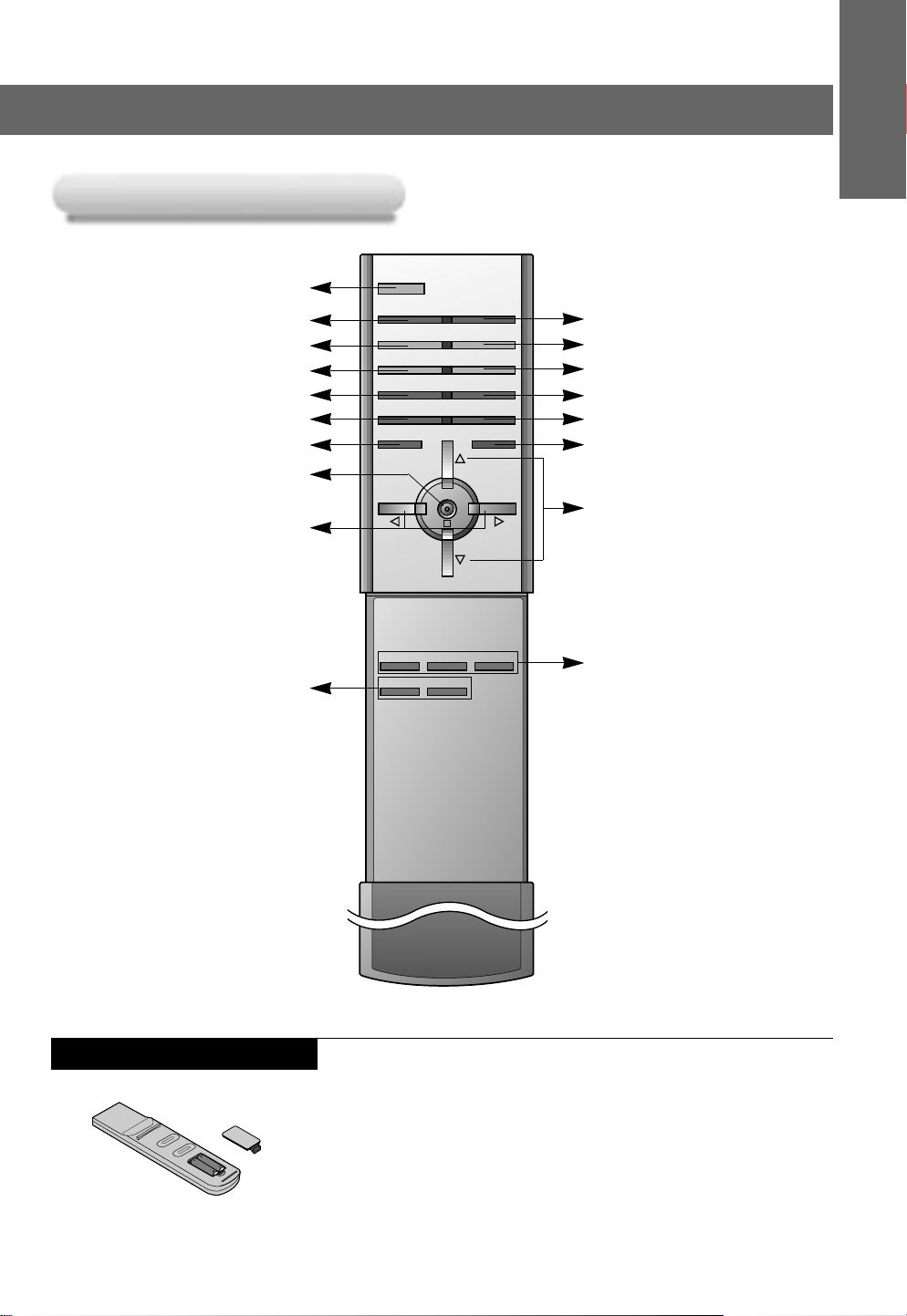
Remote Control
Remote Control
POWER Button
KEYSTONE Button(Refer to p.49)
APC Button(Refer to p.53)
AUTO TRACKING Button(Refer to p.54)
ARC Button(Refer to p.51)
SWAP Button(Refer to p.47)
MENU Button
OKA Button
VOL(
F, G) Button
INTRODUCTION
INPUT SELECT Button
STILL Button(Refer to p.38, 47)
BLANK Button(Refer to p.42)
SUB INPUT Button(Refer to p.46)
TWIN PICTURE Button(Refer to p.46)
MUTE Button
* Switches the sound on or off.
UP/DOWN buttons
ZOOM-, + Button(Refer to p.50)
Inserting the batteries
Direct input select
(VIDEO, COMPONENT, A-RGB1)
• Open the battery compartment cover on the back of the
remote control and insert the batteries with correct polarity,
match “+” with “+”, and match “-” with “-”.
• Install two 1.5V “AAA” alkaline batteries.
Don’t mix used batteries with new batteries.
Button
15
Page 16
Names of parts
RR
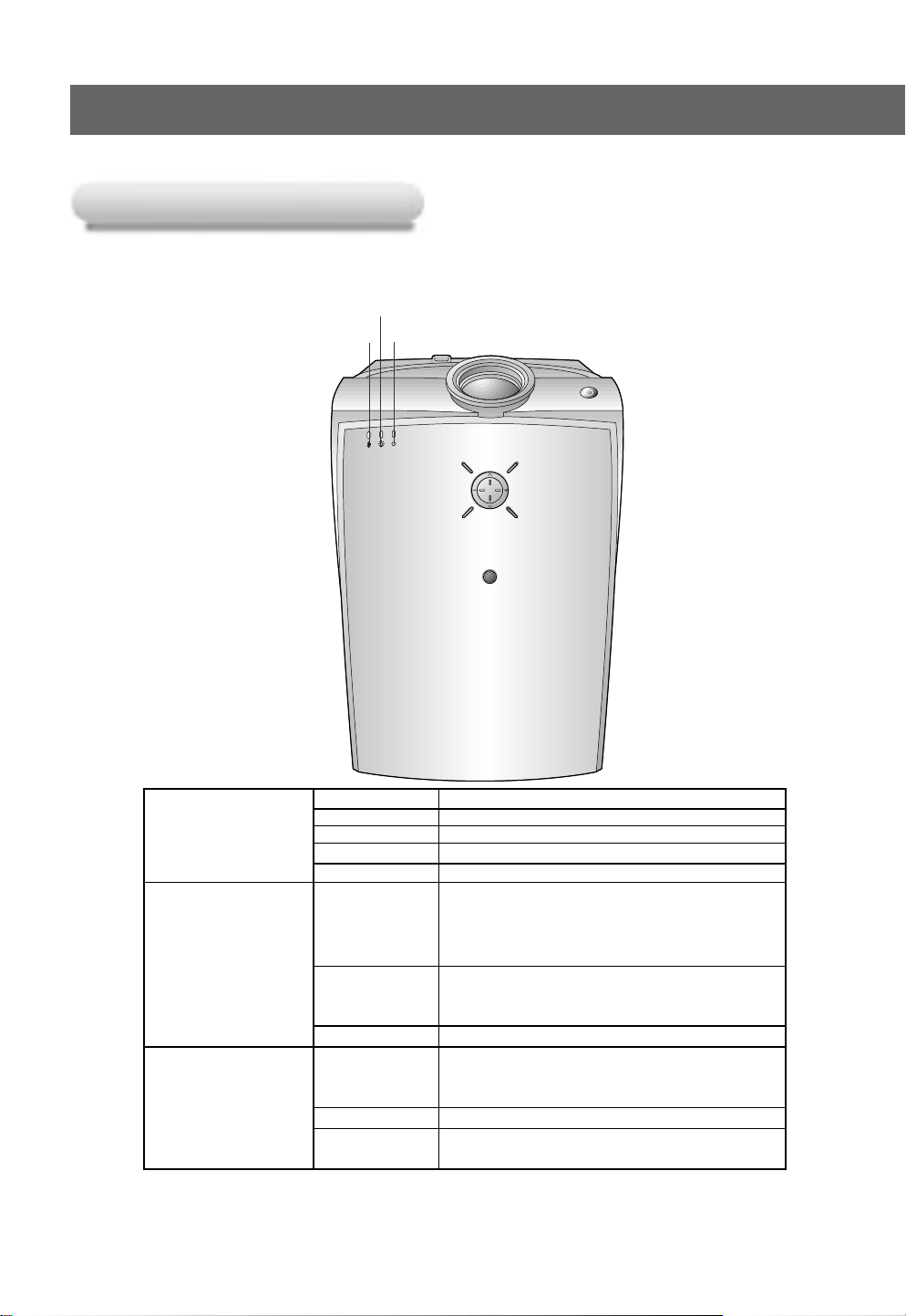
Projector Status Indicators
Projector Status Indicators
* Lamp Indicator, operation indicator and temperature indicator at the top of the projector show the user the operating status
of the projector.
Lamp Indicator
Temperature indicator
Operation indicator
16
Red Initializing hardware after the main power applied.
Operation Indicator Green On operation.(Turn on the lamp)
Lamp Indicator
Temperature Indicator
“ ”
is the warning message on screen.
Orange Standby.
Orange(flashing) Projector lamp is cooling as power out(2 minutes)
Off Power off.
Projector lamp is reaching the end of its life and needs
Red to be replaced with a new lamp.(over 1500 hours)
Red(flashing)
Green(flashing) The lamp cover or absorption pipe cover is not closed.
Orange
Red The projector is turned off as its high temperature.
Red (flashing)
The OSD, “Replace the Lamp” is displayed 10 seconds
from the first power on.
The projector has trouble in the lamp or around it at
power-on. Retry Power On again later. If lamp indicator
is red(flashing) again, contact the service center.
This projector is in high temperature. If you don’t
turn off the projector, it’ll be turned off automatically.
“Temperature is Too High”
Power has turned off due to problem with the
internal cooling fan. Contact your service center.
Page 17

Accessories
1.5V
1.5V
CH1 C
H2
CH
3
CH S/W
CH4CH
1
C
H2
CH
3
CH S/W
CH4
C
H1
C
H2
C
H3
CH
S/W
CH
4
CH1 C
H2
C
H3
CH
S/W
CH
4
1 2 3 4 5 6 7 8 9
ON
Accessories
POWER
INPUT SELECT
KEYSTONE
APC
STILL
AUTO TRACKING
BLANK
SUB INPUT
ARC
SWAP
PICTURE
TWIN
MENU MUTE
OK
VOLVOL
VIDEO
COMPONENT
A-RGB1
ZOOM-
ZOOM+
INTRODUCTION
Remote Control
Audio Cable
MAC Desktop
Batteries 2 (size AAA)
Computer Cable
Portable Bag
Adaptor
Optional Extras
* Contact your dealer to purchase these items.
* Contact your dealer for replacing a new lamp.
S-Video Cable
Power Cord
DVI Cable
Audio/Video Cable
SCARTto RCA jack (option)
Operating guide
DVI to VGA Cable
Projection Screen
Lamp
A/V wireless
transmitter-receiver
* See A/V wireless transmitter-
receiver operating guide for
installation and connection etc.
17
Page 18
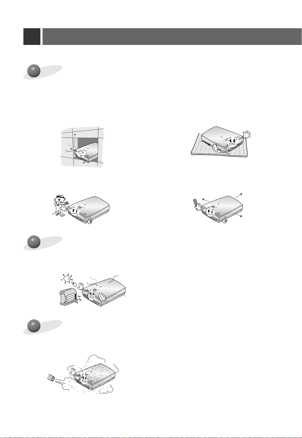
Installation Instructions
R
R
R
R
R
R
*
Don’t place the projector in the following conditions. It may cause malfunction or product damage.
Provide proper ventilation for this projector.
●
The projector is equipped with ventilation
holes(intake) on the bottom and ventilation
holes(exhaust) on the front. do not block or
place anything near these holes, or internal
heat build-up may occur, causing picture
degradation or damage to the projector.
● Do not place the projector on a carpet, rug
or other similar surface. It may prevent a
adequate ventilation of the projector bottom. This product should be mounted to a
wall or ceiling only.
● Never push projector or spill liquid of any
kind into the projector.
● Leave an adequate distance(30cm or more)
around the projector.
Place this projector in adequate temperature and humidity conditions.
●
Install this projector only in a location where adequate temperature and humidity is available.
(refer p.67)
Don’t place the projector where it can be covered with dust.
●
This may cause overheating of the projector. Clean the Air filter periodically.
18
Page 19
Do not obstruct the slots and openings of the projector. This may cause overheating
R
and create a fire hazard.
The LCD projector is manufactured using high-precision technology.
You may , however, see tiny black points and/or bright points (red, blue, or green) that
continuously appear on the LCD projector Screen. This is a normal result of the manufacturing process and does not indicate a malfunction.
To display DTV programmes, it is necessary to connect a DTV receiver (Set-top Box)
and connect it to the projector.
COMPOSITION
INST ALLA TION AND
If there is no input signal, the Menu will not be displayed on screen.
19
Page 20
Composition
Basic Operation of the Projector
Basic Operation of the Projector
1. Place the projector on a sturdy and horizontal surface with the PC or AV source.
1
2. Place the projector the correct distance from the screen. The distance between the projector and the screen
2
determines the actual size of the image.
3. Position the projector so that the lens is set at a right angle to the screen. If the projector is not set at a right angle,
3
the screen image will be crooked. If this is so then the keystone adjustment may correct this (Refer to page 49.)
4. Connect the cables of the projector to a wall power socket and other connected sources.
4
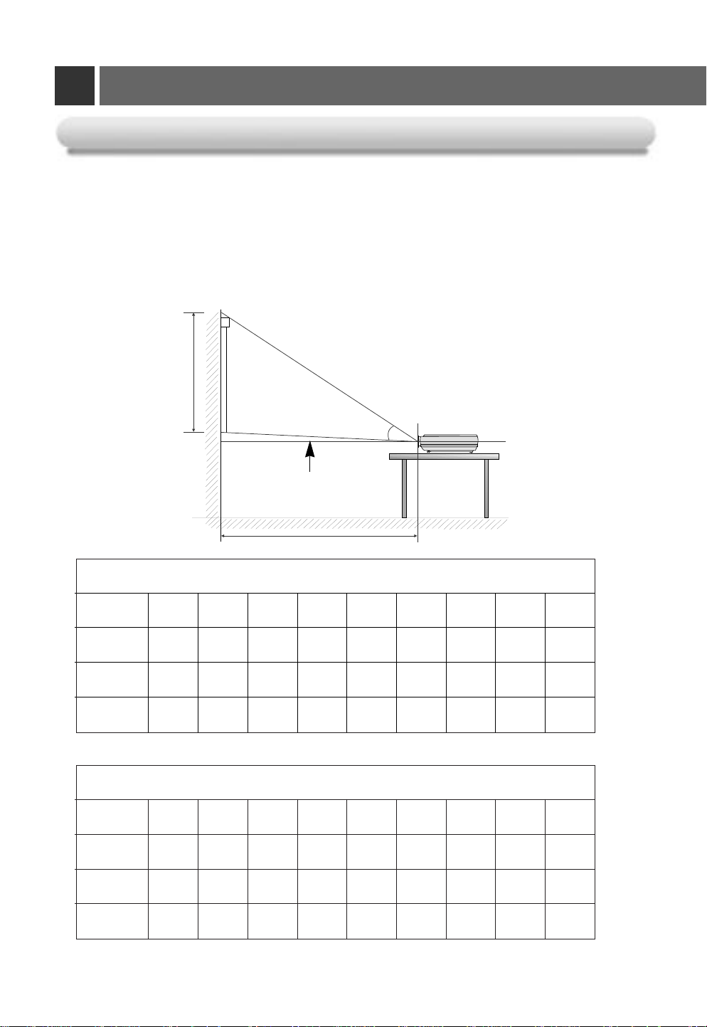
projection distance based on the picture format
Projection off-set ratio:114%
Screen height (X)
Center line of lens
Projection distance (D)
16:9 picture format mm
screen
size
screen
height (X)
The shortest
distance (D)
The longest
distance (D)
* The longest/shortest distance show status when adjusted by the zoom function.
screen
size
screen
height (X)
The shortest
distance (D)
The longest
distance (D)
″ 60″ 80″ 90″ 100″ 110″ 120″ 150″ 200″
40
498 747 996 1121 1245 1370 1494 1868 2491
1715 2572 3430 3859 4287 4716 5145 6431 8575
2229 3344 4459 5016 5574 6131 6688 8361 11147
4:3 picture format mm
40″ 60″ 80″ 90″ 100″ 110″ 120″ 150″ 200″
610 914 1219 1372 1524 1676 1829 2286 3048
2099 3148 4198 4722 5247 5772 6297 7871 10494
2729 4093 5457 6139 6821 7503 8186 10232 13643
20
Page 21
Using Kensington Security System
K
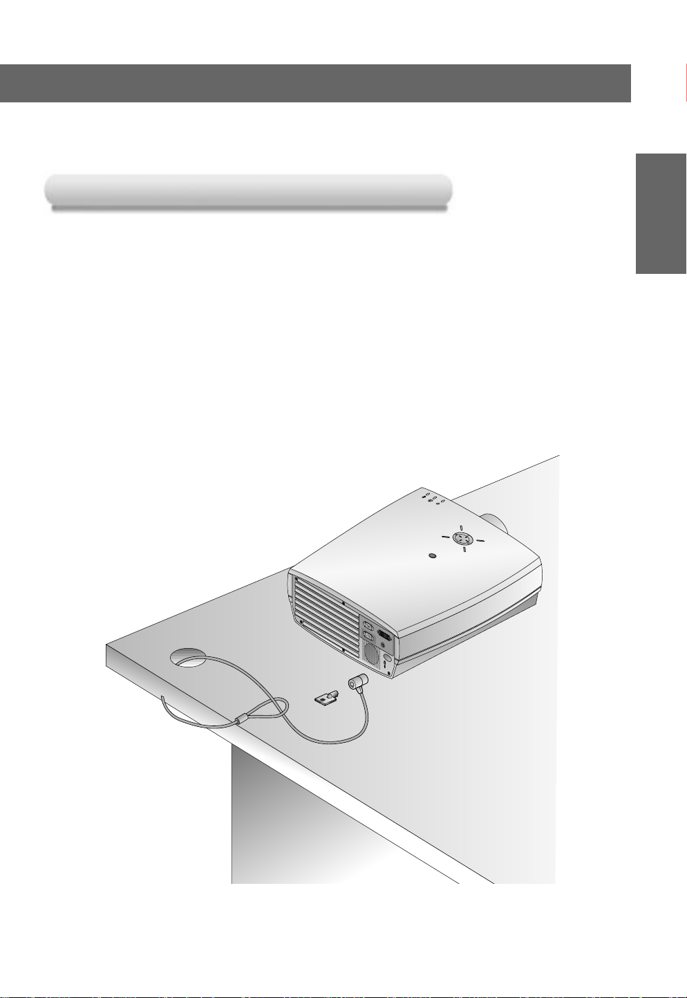
Using Kensington Security System
●
The projector has a ‘Kensington’ Security System Connector on the back panel. Connect the ‘Kensington’
Security system cable as below.
●
For the detailed installation and use of the Kensington Security System, refer to the user’s guide
attached to the Kensington Security System set.
And for further information, contact http://www.kensington.com, the internet homepage of the
Kensington company that deals with expensive electronic equipments such as notebook PCs or LCD
projectors.
●
Kensington Security System is an optional item.
COMPOSITION
INST ALLA TION AND
21
Page 22

Turning on the Projector
24
R
Connect power cord correctly.
1
Remove the lens cover of the projector.
2
Press the POWER button on the remote control or top cover.(Green operation indicator flashes
during cooling of the lamp.)
3
● It will take about 1 minute to display the picture after power on because the projector lamp has to
warm up.
● An image will appear after the operation indicator light up(Green).
● Select the source mode with the INPUT SELECT button.
● Leave the projector plugged in for at least 2 minutes after switching off the projector, as this
will allow the lamp cooling to continue which will help to preserve the lamp life.
Adjust volume level.
4
●
If you press VOLUME G button, sound and volume level number are increased.
●
If you press VOLUME F button, sound and volume level number are decreased.
22
* Don’t turn main power off and don’t unplug the power cord while the ventilation
fan(inlet/outlet) is working.
Page 23

Turning off the Projector
Press the POWER button on the top cover or remote control.
1
Power Off?
Please Press Key Again.
Press the POWER button on the top cover or remote control again to cut off the power.
2
COMPOSITION
INST ALLATION AND
If the operation indicator LED is orange and blinking, do not disconnect the mains supply
until the operation indicator LED is lit up constantly (orange).
3
●
If the operation indicator LED is orange and blinking, the power button on the top cover
or on the remote control will not operate.
23
Page 24

Operating the Projector
R
R
R
Focus and Position of the Screen Image
Focus and Position of the Screen Image
When an image appears on the screen, check if it is in focus and fits well to the screen.
Focus ringZoom ring
● To adjust the focus of the image, rotate the focus ring which is the outer ring on the lens.
● To adjust the size of the image, rotate the zoom ring which is the inner ring on the lens.
To raise or lower the image on the screen, extend or retract the foot at the bottom of the projector
by pushing foot adjuster button as below.
1. Stand behind the projector and lift the foot adjuster levers while you support the front of the projector.
2. While pressing the foot adjuster button, raise or lower the projector to place the screen image in the proper position.
3. Release the button to lock the foot in its new position.
4. To fine-tune the height of the projector, rotate the front foot to raise or lower it.
After raising the front foot, do not press down on the projector.
If the projector is installed on a place that is not stable or horizontal, the projected screen shape
will be distorted.
Horizontal leveler
Horizontal leveler
● Adjust the screen shape to be horizontal and rectangular with horizontal leveler as above.
● Avoid impact or extra weight on top of the projector as it may cause the feet to alter position or damage them.
24
Page 25

Selecting source mode
Press the INPUT SELECT button.
1
select OK
F A-RGB1 G
Each press of the VOLUME (F, G) button changes the display as below.
2
A-RGB1 A-RGB2 D-RGB
COMPOSITION
INST ALLA TION AND
VideoS-VideoComponent
25
Page 26

Connecting to a Desktop PC
K
A-RGB1
RS-232C
Audio
A-RGB2/D-RGB
* You can connect the projector to a computer of VGA, SVGA, XGAand SXGA output.
* You can use ARC function for the RGB signals of the Aspect Ration 4:3. (For HD wide input signals, you cannot
use ARC function.)
* Fundamentally, HD wide input signal is not included in the Spec, so the set may not support HD signal perfectly.
* Refer to page 63 for the supported pc graphic card displays of the projector.
c
a
b
< How to connect >
a. Connect computer cable to A-RGB1 of the projector.
b. If the PC has DVI output, connect DVI cable to A-RGB2/D-RGB of the projector.
c. Connect the audio cable of PC (LINE OUT sound port) to Audio of the projector.
* If the PC has two audio out ports of SPEAKER OUT and LINE OUT, connect the LINE OUT port to get better
sound quality.
26
Page 27

Connecting to a Notebook PC
K
A-RGB1
RS-232C
Audio
A-RGB2/D-RGB
a
CONNECTION
b
< How to connect >
a. Connect computer cable to A-RGB1 of the projector.
* If you set your computer, such as a notebook type IBM PC/AT compatible, to output the signal to both the display of
your computer and the external monitor, the picture of the external monitor may not appear properly. In such cases,
set the output mode of your computer to output the signal only to the external monitor. For details, refer to the
operating instructions supplied with your computer.
* If the PC has DVI output, use DVI cable.
b. Connect the audio cable of PC (LINE OUT sound port) to Audio of the projector.
27
Page 28

Connecting to a Macintosh Desktop PC
K
A-RGB1
RS-232C
Audio
A-RGB2/D-RGB
1 2 3 4 5 6 7 8 9
ON
* You must use the Macintosh desktop adaptor to connect the projector to a Macintosh PC.
a
b
d
c
< How to connect >
a. Connect computer cable to A-RGB1 of the projector.
b. Set the adjusting number and letter of the Macintosh desktop adaptor in accordance with the resolution
you want to use and connect the adaptor to the Macintosh. (Refer to page 29 ~ 30)
c. Connect the computer cable to the Macintosh desktop adaptor.
d. Connect the audio cable of PC (LINE OUT sound port) to Audio of the projector.
28
Page 29

How to use the Macintosh desktop adaptor
1 2 3 4 5 6 7 8 9
ON
How to use the Macintosh desktop adaptor
Adjusting letter
Adjusting number
CONNECTION
a. How to use
Usually set 1 ~ 6 to OFF status and 7 ~ 9 to ON status of the adjusting numbers. And select
the adjusting letter which is correct to the Macintosh and the monitor. (Refer to page 30.)
b. Notes for Connecting to the Macintosh PowerBook
If you get problems when connecting it to the projector, set the adjusting number 9 to OFF
status and restart the Macintosh PowerBook.
29
Page 30

Connecting to a Macintosh Desktop PC
MAC llci, llsi
MAC llvi, llvx
LC
LCII
LCIII
LC 475, LC 550
LC 575
Performa
400,405,410,430,600,600CD
450
Quadra
700,900
605,610,650,800,950
840AV
Centris
610,650
660AV
PowerBook
160,165C,180,180C
DUO DOC, MINI DOC
8 24 BOARD
12¥RGB
512x384
24.5
60
N
N
N
N
N
N
N
N
N
N
N
N
N
N
N
N
N
N
output
resolution
horizontal frequency(KHz)
vertical frequency(Hz)
adjusting letter
13¥x14¥ RGB
640x480
35
66
J
J
J
J
J
J
J
J
J
J
J
J
J
J
J
J
J
J
15¥Portrait
640x870
68.8
75
O
O
O
O
O
O
O
O
O
O
O
O
O
O
VGA
640x480
31
60
G
G
M
G
G
G
G
G
G
G
G
G
G
G
G
G
SVGA
800x600
35
56
G
G
G
G
G
G
G
G
G
G
SVGA
800x600
56 or 72
G
G
G
16¥Color
832x624
50
75
F
F
F
F
F
F
F
F
F
F
F
F
F
19¥Color
1024x768
60
75
D
D
D
D
D
D
19¥Color
1024x768
60 or 70
G
G
G
2Page Mono
1150x870
68.7
75
M
M
M
M
M
M
M
M
21¥Color
1152x870
68.7
75
P
P
P
P
P
P
P
P
NTSC
NTSC
15.7
60
L
L
L
L
L
L
L
L
PAL
PAL
16
50
H
H
H
H
H
H
H
H
MACS
output spec
Adjusting letters of MAC desktop adaptor in accordance with type of MAC and output spec.
Adjusting letters of MAC desktop adaptor in accordance with type of MAC and output spec.
30
Page 31

Connecting to a Macintosh PowerBook
K
A-RGB1
RS-232C
Audio
A-RGB2/D-RGB
1 2 3 4 5 6 7 8 9
ON
a
b
CONNECTION
c
d
< How to connect >
a. Connect computer cable to A-RGB1 of the projector.
b. Set the adjusting number and letter of the Macintosh desktop adaptor in accordance with the resolution
you want to use and connect the adaptor to the Macintosh. (Refer to page 29 ~ 30)
c. Connect the computer cable to the Macintosh desktop adaptor.
d. Connect the audio cable of PC (LINE OUT sound port) to Audio of the projector.
31
Page 32

Connecting to a wireless transmitter (option)
S VIDEO
(R) AUDIO (L) VIDEO
OUT
IN
AV INPUT
AV OUTPUT
12V DC INPUT
CH1 CH2 CH3
CH S/W
CH4CH1 CH2 CH3
CH S/W
CH4
AV INPUT
• When connecting the wireless transmitter with external equipments, match the colors of
connecting ports (Video - yellow, Audio(L) - white, Audio(R) -red).
• If you have a mono VCR, connect the audio cable from the VCR to the AV input of the wireless
AV transmitter.
• See the wireless transmitter-receiver operating guide for installation and connection etc.
a
d
<Transmitter rear>
c
b
<VCR rear>
VCR
CAMCORDER
< How to connect >
a. Turn on the transmitter power and set the desired channel with channel button and direct the
wireless AV transmitter toward the wireless receiver.
b. Connect the output jacks of the VCR to the AV OUTPUT jacks of the wireless AV transmitter.
c. Connect the adaptor to the DC input of the wireless AV transmitter .
d. Connect the power plug to the wall outlet socket after connecting the power cord to the adaptor.
32
Page 33

Connecting to a wireless receiver (option)
12V DC INPUT
CH1 CH2 CH3
CH S/W
CH4CH1 CH2 CH3
CH S/W
CH4
AV INPUT
Y PBP
R
Video
S-Video
Audio
DC 12V OUT
Component (DVD/DTV)
R
AC IN
INPUT SELECT
PATTERN
POWER
MENU
VOL
VOL
OK
/
• When connecting the wireless receiver with external equipment, match the colors of connecting
jacks: Video-yellow, Left Audio-white), Right Audio-Red.
a
<Receiver rear>
b
<Side panel of the Projector>
c
< How to connect >
a. Turn the power button of the receiver on, and adjust the channel number to match the channel
number of the transmitter, with the channel button. Direct the wireless AV receiver toward the
wireless transmitter.
CONNECTION
b. Connect the AV input ports of the projector to the AV INPUT port of the receiver.
c. Connect the DC output of the projector to the DC input of the wireless receiver with the DC
cable.
33
Page 34

Connecting to a Video Source
R
INPUT
SELECT
PATTERN
POWER
MENU
AC IN
Y PBP
R
Video
S-Video
Audio
DC 12V OUT
Component (DVD/DTV)
S VIDEO
(R) AUDIO (L) VIDEO
OUT
IN
VOL
VOL
OK
/
* You can connect a VTR, a camcorder, a LDP or any other compatible video image source to the projector.
a
b
< How to connect 1 >
a. Connect the AV input jacks of the projector to the output jacks of the A/V source with A/V cables. If you
connect the Audio(R) of external equipment with projector, you can’t hear the sound. The video cable is
yellow and the left audio is white and right audio is red.
< How to connect 2 >
b. Connect the S-Video input jack of the projector to the S-Video output jack of an A/V source with an
S-Video cable.
Connect the Audio input jacks of the projector to the output jacks of the A/V source with an Audio cable.
* You can get better picture quality when connecting S-Video source to the projector.
34
Page 35

Connecting to a DVD
PR
PB
Y
(R) AUDIO (L)
R
INPUT
SELECT
PATTERN
POWER
MENU
AC IN
Y PBP
R
Video
S-Video
Audio
DC 12V OUT
Component (DVD/DTV)
VOL
VOL
OK
/
* The output jacks (Y, PB, PR) of the DVD might be labelled as Y, Pb, Pr / Y, B-Y, R-Y / Y, Cb, Cr according to the
equipment.
b
a
CONNECTION
<DVD rear>
< How to connect >
a. Connect the Component (DVD/DTV) ports (Y, PB, PR) of the projector to the Video output ports (Y, PB,
PR) of the DVD.
b. Connect the Audio port of the projector to the Audio output port (L) of the DVD.
c. Use a DVD with Component 480i(576i)/480p mode.
35
Page 36

Connecting to a D-TV Set-Top Box
(R) AUDIO (L)
DTV OUTPUT
PR
PB
Y
K
A-RGB1
RS-232C
Audio
A-RGB2/D-RGB
R
INPUT
SELECT
PATTERN
POWER
MENU
AC IN
Y PBP
R
Video
S-Video
Audio
DC 12V OUT
Component (DVD/DTV)
VOL
VOL
OK
/
* To receive D-TV programmes, it is necessary to purchase a D-TV receiver (Set-Top Box) and
connect it to the projector.
* Please refer to the owner's manual of the D-TV Set-Top Box for the connection between
LCD projector and D-TV Set-Top Box.
* Use a D-TV receiver with DTV 720p/1080i mode.
c
(Component)
<D-TV Set-Top Box rear>
(RGB)
(Component)
< How to connect an RGB source >
a. Connect computer cable to A-RGB1 of the projector.
* If the Set-Top Box has DVI output, use DVI cable.
b. Use a DTV receiver with DTV 720p/1080i mode.
< How to connect a Component source >
a. Connect the Component (DVD/DTV) ports (Y, PB, PR) of the projector to the Video output ports (Y, PB,
PR) of the D-TV Set-Top Box.
b. Connect the Audio port of the projector to the Audio output port (L) of the D-TV Set-Top Box.
c. Use a DTV receiver with DTV 480p/720p/1080i mode.
36
Page 37

Function checking
*
If there is no input signal present, the Menu will not be displayed on the screen.
*
This operating guide explains operation of A-RGB1 mode mainly.
Press the MENU button to display a menu on the screen.
1
Press the D, E button to select a menu.
2
● Each press will cycle through the different menus as shown below.
Contrast 50
Brightness 50
Color R 50
Color G 50
Color B 50
Reset
Menu exit move OK Menu exit move OK
Twin Picture
Color Temp. R 0
Color Temp. G 0
Color Temp. B 0
Off
Language
ARC
Flip Horizontal
Flip Vertical
Auto Tracking
Clock 25
Phase 25
Horizontal 0
Vertical 0
Menu exit move OK
V Keystone 0
H Keystone 0
Zoom
Blank Image
Set ID
Lamp Time
English
16:9
Blue
1
0 Hr
BASIC
FUNCTIONS
Menu exit move OKMenu exit move OK
Press the OK (A) button and then press the D, E or VOLUME (F, G) buttons to select a feature you
want to use.
3
● T o exit the menu display, press the MENU button.
* In Video and S-Video mode and Component(480i(576i)), D-RGB mode menu is not displayed.
* Only A-RGB1, A-RGB2, Component(480p, 720p, 1080i) mode displays [Horizontal], [Vertical] in menu
* The sub menus of menu in Video and S-Video mode and Component mode are different from those in the RGB
mode. (Refer to page 52).
* [Color R], [Color G], [Color B] : Use only for the A-RGB1 and the A-RGB2 modes. [Color R], [Color G], [Color B]
items are used to adjust the R/G/B color levels when the RGB analog input signal has improper R/G/B signal levels.
37
Page 38

Using Still function
Press the STILL button.
1
* You can freeze the input image.
<Moving Image>
To exit Pause, press any button .
2
* The STILL function would release automatically after about 10 minutes.
<Still Image>
38
Page 39

Selecting language
Press the MENU button and then use D / E button to select the menu.
1
Language
ARC
Flip Horizontal
Flip Vertical
Menu exit move OK
English
16:9
Press the OK (A) button and then use D / E button to select [Language] item.
2
3
Press the
●
On-Screen-Display(OSD) is marked in the selected language from this point.
●
To exit the menu display, press the MENU button.
VOLUME (F, G) button to select the language you want to use.
SPECIAL
FUNCTIONS
Language
ARC
Flip Horizontal
Flip Vertical
Menu prev. move select
English
16:9
39
Page 40

Checking lamp time
Press the MENU button and then use D / E button to select the menu.
1
V Keystone 0
H Keystone 0
Zoom
Blank Image
Set ID
Lamp Time
Menu exit move OK
●
The used lamp time is displayed.
●
When projector lamp is reaching the end of its life(over 1500 hours), the lamp indicator will be turned
red and the projector will display “Replace the Lamp” on screen.
●
The OSD, "Replace the Lamp" is displayed for 10 seconds from the first power on.
●
The lamp warning LED illuminates red continuously in the case of excessive lamp time.
Blue
0 Hr
1
40
Page 41

Manual Color Temperature Control
* You can adjust red, green, or blue to any color temperature you prefer.
Press the
MENU button and then use D / E button to select the menu.
1
Twin Picture
Color Temp. R 0
Color Temp. G 0
Color Temp. B 0
Menu exit move OK
Press the OK (A) button and then use D / E button to select a color.
2
Twin Picture
Color Temp. R 0
Color Temp. G 0
Color Temp. B 0
Off
SPECIAL
FUNCTIONS
Off
3
Menu prev. move adjust
Use the
●
●
VOLUME (F, G) button to make appropriate adjustments.
The adjustment range of [Color Temp. R], [Color Temp. G] and [Color Temp. B] is -50 ~ +50.
To exit the menu display, press the MENU button.
41
Page 42

Using Blank function
* This function may be effective if you need to get attention of the audience during presentations, meetings
or briefings.
Press the BLANK button.
1
*
The screen turns off to a background color and sound also turns off.
* You can choose the background color. Refer to page 43.
Press any button to cancel the blank function.
2
*
On exiting the blank status sound is also restored.
42
Page 43

Selecting Blank Image color
Selecting Blank Image color
Press the MENU button and then use D / E button to select the menu.
1
V Keystone 0
H Keystone 0
Zoom
Blank Image
Set ID
Lamp Time
Menu exit move OK
Blue
0 Hr
1
Press the OK (A) button and then use D / E button to select [Blank Image] item.
2
SPECIAL
FUNCTIONS
Press the VOLUME (F, G) button to select the color you want to use.
3
●
Background color will be changed to the selected Blank function color from this point.
●
To exit menu display, press the MENU button.
V Keystone 0
H Keystone 0
Zoom
Blank Image
Set ID
Lamp Time
Menu prev. move select
Blue
1
0 Hr
43
Page 44

Using Flip Horizontal / Vertical function
Flip Horizontal Function
Flip Horizontal Function
* This function reverses the projected image horizontally. Use this function when rear projecting an image.
Press the MENU button and then use D / E button to select the menu.
1
Language
ARC
Flip Horizontal
Flip Vertical
Menu exit move OK
English
16:9
Press the OK (A) button and then use D / E button to select [Flip Horizontal] item.
2
English
16:9
Press OK to Flip
Press the
OK(
) button to see reversed image.
A
Language
ARC
Flip Horizontal
Flip Vertical
Menu prev move OK
3
●
Each time you press the button, the image will be reversed.
●
To exit the menu display, press the MENU button.
44
Page 45

Flip V
Flip V
* This function reverses the projected image vertically.
* When you hang the projector upside down from the ceiling , you will need to reverse the image vertically and
horizontally.
ertical Function
ertical Function
Press the MENU button and then use D / E button to select the menu.
1
Language
ARC
Flip Horizontal
Flip Vertical
Menu exit move OK
English
16:9
Press the OK (A) button and then use D / E button to select [Flip Horizontal] item.
2
English
16:9
Press OK to Flip
Press the
OK(
) button to see reversed image.
A
Language
ARC
Flip Horizontal
Flip Vertical
Menu prev move OK
3
●
Each time you press the button, the image will be reversed.
●
To exit the menu display, press the MENU button.
SPECIAL
FUNCTIONS
45
Page 46

TITLE
PICTURE
TWIN
Twin Picture function
How to use twin picture
Press the TWIN PICTURE button to select desired with picture.
Twin Picture1
Twin Picture 1
● You can use this function by using the MENU button.
Twin Picture 2 Twin Picture : Off
Twin Picture : Off
Twin Picture 2
Input select of the sub picture
Press the SUB INPUT button to select the input source of sub picture.
SUB INPUT
select OK
F A-RGB1 G
46
Page 47

Changing the picture of main and sub picture
Press the SWAP button in twin picture mode.
SWAP
A-RGB2
Video
Using Still function in twin picture mode.
STILL
Press the STILL button in twin picture mode.
Video
A-RGB2
SPECIAL
FUNCTIONS
Main Still
Sub Still
exit select
● You can cancel this function directly by selecting [Off] in menu.
●
The STILL function is cancelled when changing the input signal.
[Main Still] is cancelled when changing the input signal with
Off
Off
INPUT SELECT
button and [Sub Still] is cancelled when changing the input signal with
SUB INPUT button. That is, [Main/Sub Still] work separately.
●
The STILL function would release automatically after about 10 minutes.
47
Page 48

Adjusting screen display
*If the image size does not fit the screen in accordance with the input source, set the position of the image
by selecting Horizontal / Vertical position.(For A-RGB1, A-RGB2, Component 480p/720p/1080i)
Press the MENU button and then use D / E button to select the menu.
1
Auto Tracking
Clock 25
Phase 25
Horizontal 0
Vertical 0
Menu exit move OK
Press the OK (A) button and then use D / E button to select [Horizontal] or [Vertical] item.
2
Auto Tracking
Clock 25
Phase 25
Horizontal 0
Vertical 0
Menu prev. move adjust
VOLUME (F, G) button to adjust the screen condition as you want.
3
Press the
●
[Horizontal], [Vertical] are adjusted from -50 to +50.
●
To exit the menu display, press the MENU button.
48
Page 49

Using Keystone function
*Use this function when the screen is not at a right angle to the projector and the image is a
trapezoid shape.
*Only use the Keystone function when you can’t get the best angle of projection, because it
may cause a blazing fire of the screen.
Press the KEYSTONE button.
1
V Keystone 0
H Keystone 0
exit adjust
Press the
D / E button to select [V Keystone] or [H Keystone] item.
2
Press the VOLUME (F, G) button to adjust the screen condition as you want.
3
●
[Keystone]
●
Adjustment range of H/V Keystone may not work until -50 ~ +50 because they are interlocked.
●
Based on the input resolution or twin picture mode, the adjustment range of Keystone may be different.
●
To exit the menu display, press the OK (A) button.
● You can also use this function by using the MENU button.
are adjusted from -50 to +50.
ING
POSITION-
49
Page 50

Using Zoom function
R
* This function works only in RGB mode.
Press the ZOOM - or ZOOM + button.
1
0/20
ZOOM+
ZOOM-
Press the ZOOM - or ZOOM + button to adjust the zoom level.
2
15/20 20/20
ZOOM+
ZOOM-
Move to the position you want to see the enlarged screen by moving press the VOLUME (F, G) ,
D, E button.
3
Press the OK (A) or ARC button to exit the zoom function.
ZOOM-
ZOOM+
4
* This function doesn’t work in Video, S-Video, Component mode.
* You can use this function by using the MENU button.
* In the zoom mode, you can adjust horizontal / vertical position with the
VOLUME (F, G) , D, E
button during displaying zoom OSD.
50
Page 51

Using ARC function
R
* You can select 16:9 picture format only with an HD input (720p,1080i) mode.
Press the ARC button.
1
Each press of the button changes the display as below.
< A-RGB1/A-RGB2/D-RGB mode >
16:9
F
16:9
G
16:9
F
G
ARC
< Video/S-Video/Component(480i(576i), 480p) mode >
ARC
ARC
ARC
4 : 3
4:3
F
G
4:3
F
G
22% Magnification
16:9
Zoom4
F
ARC
22% Magnification
G
4 : 3
ARC
Zoom1
F
Zoom1
17% Magnification
G
Zoom4
22% Magnification
ARC
Zoom3
F
Zoom3
Zoom2
F
G
ARC
G
17% Magnification
17% Magnification
Zoom2
* Zoom1
Select to stretch the normal image vertically (about 17% ). Part of the top and bottom of the image will not be visible and black bars may
appear at top and bottom of screen for some input sources.
* Zoom2
Select to stretch the normal picture both vertically and horizontally (about 17% ) to provide an enlarged and distortion free image.
* Zoom3
Select to stretch the normal picture vertically (about 22% of original picture format).
* Zoom4
Select to stretch the normal picture both vertically and horizontally (about 22% ) to provide an enlarged and distortion free image.
ING
POSITION-
* You can also use this function by using the MENU button.
51
Page 52

Adjusting Video
Press the MENU button and move the D / E button up or down to select each menu.
1
< RGB mode >
Contrast 50
Brightness 50
Color R 50
Color G 50
Color B 50
Reset
Menu exit move OK
Press the OK (A) button.
2
< RGB mode >
Contrast 50
Brightness 50
Color R 50
Color G 50
Color B 50
Reset
Menu Prev. move adjust
< Video, S-Video, Component mode >
APC
Contrast 50
Brightness 50
Color 50
Sharpness 50
Tint 0
Menu exit move OK
User
< Video, S-Video, Component mode >
APC
Contrast 50
Brightness 50
Color 50
Sharpness 50
Tint 0
Menu Prev. move select
User
< Twin picture mode >
Contrast 50
Brightness 50
Reset
Menu exit move OK
< Twin picture mode >
Contrast 50
Brightness 50
Reset
Menu Prev. move adjust
Press the D / E button up or down to select a video item you want to adjust.
3
Press the VOLUME (F, G) button to adjust the selected video item as you want.
4
●
You can only adjust [Contrast] and [Brightness] of menu in Twin picture mode. In Twin picture mode,
adjustment for [Contrast] and [Brightness] will not affect other input sources. Adjustments apply to main and
sub picture simultaneously.
●
Each adjustment of menu options will not affect other input source. As required, re-adjust menu
options for the following input source : Video/S-Video/Component(480i(576i)), Component(480p, 720p, 1080i)
●
T o restore the original image condition after changing it, press OK (A) button after selecting [Reset] item.
●
In the broadcasting system NTSC, the picture item Tint is displayed and can be adjusted.
●
To exit the menu display, press the MENU button.
52
Page 53

APC (Auto Picture Control)
R
APC (Auto Picture Control)
* Use APC to set the projector for the best picture appearance.
* This function will not work in RGB mode.
Press the APC button.
1
User
F
APC
G
Each press of the APC button changes the screen as shown below.
2
User Clear Soft
* You can also use this function by using the MENU button.
(Video/S-Video/Component mode)
VIDEO
53
Page 54

Using Tracking function
R
Auto T
Auto T
* Auto Tracking Function
This function assures you of getting the best video quality by automatically adjusting the difference of horizontal size and
synchronization of the image.
Auto Tracking function works in Analog RGB(A-RGB1, A-RGB2) input only.
Press the AUTO TRACKING button.
racking Function
racking Function
1
Auto Tracking
* Image positioning and synchronization are automatically adjusted.
Adjust [Clock] or [Phase] in menu after operation of [Auto Tracking] if you want to get bet-
2
ter picture quality in accordance with diverse Analog RGB(A-RGB1, A-RGB2) input modes.
In certain circumstances, you can’t get the best picture quality only with auto-correction.
(Refer to page 55.)
* You can also use this function by using the MENU button.(Only in Analog RGB
mode)
* For best results, perform this function while displaying a still image.
54
Page 55

Clock / Phase Function
Clock / Phase Function
* Clock Function
This function adjusts the horizontal width of the projected image to get the image to fit on the screen size.
* Phase Function
This function is for the detailed adjustment of the clock function.
* It’s available to adjust [Clock], [Phase] in Analog RGB mode only.
Press the MENU button and then use D / E button to select the menu.
1
Auto Tracking
Clock 25
Phase 25
Horizontal 0
Vertical 0
Menu exit move OK
Press the OK (A) button and then use D / E button to select [Clock] or [Phase] item.
2
Auto Tracking
Clock 25
Phase 25
Horizontal 0
Vertical 0
Menu prev. move adjust
VOLUME (F, G) button to adjust the screen condition.
3
Press the
●
To exit the menu display, press the MENU button.
TRACKING
55
Page 56

External control device setup
*
Connect the RS-232C input jack to an external control device (such as a computer or an A/V control system)
and control the Projector’s functions externally.
* When you connect a control(RS-232C) cable to this projector, use a control cable with a ferrite core attached.
If you do not do this, this projector will not conform to mandatory CISPR22(EN55022) standards.
SET ID
• Use this function to specify projector ID number.
Press the MENU button and then use D / E button to select the menu.
1
V Keystone 0
H Keystone 0
Zoom
Blank Image
Set ID
Lamp Time
Menu exit move OK
Blue
0 Hr
1
Press the OK (A) button and then use D / E button to select [Set ID] item.
2
Press the VOLUME (F, G) button to adjust Set ID to select the desired projector ID number.
3
●
The adjustment range of Set ID is 1~99.
●
Only the projector with the specified ID number will operate from the remote control.
●
To exit the menu display, press the MENU button.
V Keystone 0
H Keystone 0
56
Zoom
Blank Image
Set ID
Lamp Time
Menu prev. move select
Blue
1
0 Hr
Page 57

How to connect external control equipment
K
A-RGB1
RS-232C
Audio
A-RGB2/D-RGB
• Connect the serial port of the PC to the RS-232C jack on the projector back panel.
• RS-232C cable is not supplied with the projector.
• Use the RS232C cable to control the projector externally (Refer to Fig.1).
<Fig.1, RS-232 Interface Cable>
RXD
2
TXD
3
GND
5
DTR
4
DSR
6
RTS
7
CTS
8
Male
(-)
* 1, 9 Pin No Connection
3
2
5
4
6
7
8
Female
(-)
TXD
RXD
GND
DTR
DSR
RTS
CTS
Communication Parameter Setup
• Baud Rate : 19200 bps(UART)
• Data Length : 8 bit
• Parity : none
• Stop bit : 1 bit
• Flow Control : none
• Communication code : ASCII code
RS-232C
57
Page 58

External control device setup
Command Reference List
01. Power k 0 0 00~63 00, 01
02. Input Select k 0 1 00~63 00~05
03. Aspect Ratio k 0 2 00~63 00~05
04. Screen Mute k 0 3 00~63 00, 01
05. Sub Input Select k 0 4 00~63 00~05
06. Contrast k 3 0 00~63 00~64
07. Brightness k 3 1 00~63 00~64
08. Color k 3 2 00~63 00~64
09. Tint k 3 3 00~63 00~64
10. Sharpness k 3 4 00~63 00~64
11. Color R k 3 6 00~63 00~64
12. Color G k 3 7 00~63 00~64
13. Color B k 3 8 00~63 00~64
14. Color Temp. R k 3 9
15. Color Temp. G k 3 a
16. Color Temp. B k 3 b
17.
Twin Picture Mode Select k 4 1 00~63 00, 01, 02
18. Volume Mute k 5 4 00~63 00, 01
19. Volume Control k 5 0 00~63 00~64
20. OSD Lock mode k 9 0 00~63 00, 01
21.
Remote Control Lock mode
Command1 Command2-1 Command2-2 SET ID Data(Hexa) Data(Hexa)
00~63 00~64
00~63 00~64
00~63 00~64
k 9 1 00~63 00, 01
❑ Communication Protocol
ransmission
1. T
[Command1][Command2-1][Command2-2][ ][Set ID][ ][Data][Cr]
[Command 1] : To classify factory adjustment mode or user adjustment mode.(ASCII code, 1 Character)
*
[Command 2-1] : Group classification code to control set.(ASCII code, 1 Character)
*
[Command 2-2] : To control projector set.
*
[Set ID] : You can adjust the set ID to choose desired projector ID number in special menu. See previous page.
*
[DATA] : To transmit command data. Transmit 2 character when organized ASCII code.
*
[Cr] : Carriage Return
*
[ ] : ASCII code character correspond to “Space Bar” which is in order to classify command set ID and Data.
*
➜ Shortening Key Group :0, Video Group : 3, Twin Picture Group : 4, Audio Group:5, Others : 9
Adjustment range is 1 ~ 99. When selecting Set ID ‘0’, every connected projector set is controlled.
* Transmit ‘FF’ data to read status of command.
ASCII code ‘0x0D’
[Command2-1][Command2-2][ ][Set ID][ ][OK][Data][X]
* The Projector transmits ACK (acknowledgement) based on this format when receiving normal data. At this time, if the data is
data read mode, it indicates present status data. If the data is data write mode, it returns the data of the PC computer.
2. Error Acknowledge
[Command2-1][Command2-2][ ][Set ID][ ][NG][Data][X]
* The Projector transmits ACK (acknowledgement) based on this format when receiving abnormal data from non-viable
functions or communication errors.
Data : [01] : illegal code(This command is not supported.)
[02] : not support function(This function doesn’t work.)
[03] : wait more time(Try again a few minute later.)
58
Page 59

01. Power (Command2-1:0, Command2-2:0)
➜ To control Power On/Off of the Projector.
Transmission
[k] [0] [0] [Set ID] [ ] [Data] [Cr]
Data 00 : Power Off
01 : Power On
Ack
[0] [0] [ ] [Set ID] [ ] [OK] [Data] [X]
Data 00 : Power Off
01 : Power On
➜ To show Power On/Off status.
Transmission
[k] [0] [0] [ ] [Set ID] [ ] [FF] [Cr]
Ack
[0] [0] [ ] [Set ID] [ ] [OK] [Data] [X]
Data 00 : Power Off
01 : Power On
* In like manner, if other functions transmit
‘FF’ data based on this format,
Acknowledgement data feed back presents
status about each function.
03. Aspect Ratio (Command2-1:0, Command2-2:2)
➜ To adjust the screen format.
Transmission
[k] [0] [2] [ ] [Set ID] [ ] [Data] [Cr]
Data 00 : Wide Screen(16:9) 01 : Normal Screen( 4:3)
02 : Zoom 1 03 : Zoom 2
04 : Zoom 3 05 : Zoom 4
Ack
[0] [2] [ ] [Set ID] [ ] [OK] [Data] [X]
Data 00 : Wide Screen(16:9) 01 : Normal Screen( 4:3)
02 : Zoom 1 03 : Zoom 2
04 : Zoom 3 05 : Zoom 4
* Using the PC input, you select either 16:9 or 4:3 screen
aspect ratio.
* Screen size function doesn’t work with HD signal.
* Zoom1~Zoom4 mode works only with Video/S-Video/
Component(480i(576i), 480p) input.
04. Screen Mute (Command2-1:0, Command2-2:3)
➜ To select screen mute on/off.
Transmission
[k] [0] [3] [ ] [Set ID] [ ] [Data] [Cr]
Data 01 : Screen Mute On (Picture Off)
00 : Screen Mute Off (Picture On)
02. Input Select (Command2-1:0, Command2-2:1)
➜ To select input source for the Set.
Transmission
[k] [0] [1] [ ] [Set ID] [ ] [Data] [Cr]
Data 00 : A-RGB1 01 : A-RGB2 02 : D-RGB
03 : Video 04 : S-Video 05 : Component
Ack
[0] [1] [ ] [Set ID] [ ] [OK] [Data] [X]
Data 00 : A-RGB1 01 : A-RGB2 02 : D-RGB
03 : Video 04 : S-Video 05 : Component
Ack
[0] [3] [ ] [Set ID] [ ] [OK] [Data] [X]
Data 01 : Screen Mute On (Picture Off)
00 : Screen Mute Off (Picture On)
05. Sub Input Select
(Command2-1:0, Command2-2:4)
➜ To select input source for sub picture.
Transmission
[k] [0] [4] [ ] [Set ID] [ ] [Data] [Cr]
Data 00 : A-RGB1 01 : A-RGB2 02 : D-RGB
03 : Video 04 : S-Video 05 : Component
Ack
[0] [4] [ ] [Set ID] [ ] [OK] [Data] [X]
Data 00 : A-RGB1 01 : A-RGB2 02 : D-RGB
03 : Video 04 : S-Video 05 : Component
RS-232C
59
Page 60

External control device setup
06. Contrast (Command2-1:3, Command2-2:0)
➜ To adjust screen contrast.
Transmission
[k] [3] [0] [ ] [Set ID] [ ] [Data] [Cr]
Data Min : 00 ~ Max : 64
Refer to ‘Real data mapping 1’.
*
* Always marks data value with Hexadecimal.
That is, marks with two-place Hexadecimal
while writing and read data is also marked with
Hexadecimal value.
Ack
[3] [0] [ ] [Set ID] [ ] [OK] [Data] [X]
Data Min : 00 ~ Max : 64
07. Brightness (Command2-1:3, Command2-2:1)
➜ To adjust screen brightness.
Transmission
[k] [3] [1] [ ] [Set ID] [ ] [Data] [Cr]
Data Min : 00 ~ Max : 64
Refer to ‘Real data mapping 1’.
*
* Always marks data value with Hexadecimal.
That is, marks with two-place Hexadecimal
while writing and read data is also marked with
Hexadecimal value.
Ack
[3] [1] [ ] [Set ID] [ ] [OK] [Data] [X]
Data Min : 00 ~ Max : 64
9. Tint (Command2-1:3, Command2-2:3)
➜ To adjust the screen tint.
Transmission
[k] [3] [3] [ ] [Set ID] [ ] [Data] [Cr]
Data Red : 00 ~ Green : 64
Refer to ‘Real data mapping2’.
*
* Always marks data value with Hexadecimal.
That is, marks with two-place Hexadecimal
while writing and read data is also marked with
Hexadecimal value.
Ack
[3] [3] [ ] [Set ID] [ ] [OK] [Data] [X]
Data Red : 00 ~ Green : 64
Real data mapping 1
*
0 : Step 0
A : Step 10
F : Step 15
10 : Step 16
64 : Step 100
* This is a Hexadecimal number data.
Real data mapping 2
*
0 : Step -50
32 : Step 0
64 : Step 50
08. Color (Command2-1:3, Command2-2:2)
➜ To adjust the screen color.
Transmission
[k] [3] [2] [ ] [Set ID] [ ] [Data] [Cr]
Data Min : 00 ~ Max : 64
Refer to ‘Real data mapping 1’.
*
* Always marks data value with Hexadecimal.
That is, marks with two-place Hexadecimal
while writing and read data is also marked with
Hexadecimal value.
Ack
[3] [2] [ ] [Set ID] [ ] [OK] [Data] [X]
Data Min : 00 ~ Max : 64
60
10. Sharpness (Command2-1:3, Command2-2:4)
➜ To adjust the screen sharpness.
Transmission
[k] [3] [4] [ ] [Set ID] [ ] [Data] [Cr]
Data Min : 00 ~ Max : 64
Refer to ‘Real data mapping 1’.
*
* Always marks data value with Hexadecimal.
That is, marks with two-place Hexadecimal
while writing and read data is also marked with
Hexadecimal value.
Ack
[3] [4] [ ] [Set ID] [ ] [OK] [Data] [X]
Data Min : 00 ~ Max : 64
Page 61

11. Color R Adjustment
(Command2-1:3, Command2-2:6)
➜ To adjust red in color temperature.
Transmission
[k] [3] [6] [ ] [Set ID] [ ] [Data] [Cr]
Data Min : 00 ~ Max : 64
Refer to ‘Real data mapping 1’.
*
* Always marks data value with Hexadecimal.
That is, marks with two-place Hexadecimal
while writing and read data is also marked with
Hexadecimal value.
Ack
[3] [6] [ ] [Set ID] [ ] [OK] [Data] [X]
Data Min : 00 ~ Max : 64
14. Color Temp. R
(Command2-1:3, Command2-2:9)
➜ Adjust the color temperature R of LCD part.
Transmission
[k] [3] [9] [ ] [Set ID] [ ] [Data] [Cr]
Data Min : 00 ~ Max : 64
Refer to ‘Real data mapping 1’.
*
* Always marks data value with Hexadecimal.
That is, marks with two-place Hexadecimal
while writing and read data is also marked with
Hexadecimal value.
Ack
[3] [9] [ ] [Set ID] [ ] [OK] [Data] [X]
Data Min : 00 ~ Max : 64
12. Color G Adjustment
(Command2-1:3, Command2-2:7)
➜ To adjust green in color temperature.
Transmission
[k] [3] [7] [ ] [Set ID] [ ] [Data] [Cr]
Data Min : 00 ~ Max : 64
Refer to ‘Real data mapping 1’.
*
* Always marks data value with Hexadecimal.
That is, marks with two-place Hexadecimal
while writing and read data is also marked with
Hexadecimal value.
Ack
[3] [7] [ ] [Set ID] [ ] [OK] [Data] [X]
Data Min : 00 ~ Max : 64
13. Color B Adjustment
(Command2-1:3, Command2-2:8)
➜ To adjust blue in color temperature.
Transmission
[k] [3] [8] [ ] [Set ID] [ ] [Data] [Cr]
Data Min : 00 ~ Max : 64
Refer to ‘Real data mapping 1’.
*
* Always marks data value with Hexadecimal.
That is, marks with two-place Hexadecimal
while writing and read data is also marked with
Hexadecimal value.
Ack
[3] [8] [ ] [Set ID] [ ] [OK] [Data] [X]
Data Min : 00 ~ Max : 64
15. Color Temp. G
(Command2-1:3, Command2-2:a)
➜ Adjust the color temperature G of LCD part.
Transmission
[k] [3] [a] [ ] [Set ID] [ ] [Data] [Cr]
Data Min : 00 ~ Max : 64
Refer to ‘Real data mapping 1’.
*
* Always marks data value with Hexadecimal.
That is, marks with two-place Hexadecimal
while writing and read data is also marked with
Hexadecimal value.
Ack
[3] [a] [ ] [Set ID] [ ] [OK] [Data] [X]
Data Min : 00 ~ Max : 64
16. Color Temp. B
(Command2-1:3, Command2-2:b)
➜ Adjust the color temperature B of LCD part.
Transmission
[k] [3] [b] [ ] [Set ID] [ ] [Data] [Cr]
Data Min : 00 ~ Max : 64
Refer to ‘Real data mapping 1’.
*
* Always marks data value with Hexadecimal.
That is, marks with two-place Hexadecimal
while writing and read data is also marked with
Hexadecimal value.
Ack
[3] [b] [ ] [Set ID] [ ] [OK] [Data] [X]
Data Min : 00 ~ Max : 64
RS-232C
61
Page 62

External control device setup
17. Twin Picture Mode Select
(Command2-1:4, Command2-2:1)
➜ To control the twin picture.
Transmission
[k] [4] [1] [ ] [Set ID] [ ] [Data] [Cr]
Data 00 : FULL 01 : TWIN 1 02 : TWIN 2
Ack
[4] [1] [ ] [Set ID] [ ] [OK] [Data] [X]
Data 00 : FULL 01 : TWIN 1 02 : TWIN 2
18. Volume Mute (Command2-1:5, Command2-2:4)
➜ To control volume mute on/off.
Transmission
[k] [5] [4] [ ] [Set ID] [ ] [Data] [Cr]
Data 00 : Volume Mute On (Volume Off)
01 : Volume Mute Off (Volume On)
Ack
[5] [4] [ ] [Set ID] [ ] [OK] [Data] [X]
Data 00 : Volume Mute On (Volume Off)
01 : Volume Mute Off (Volume On)
19. Volume Control (Command2-1:5, Command2-2:0)
➜ To adjust volume.
Transmission
[k] [5] [0] [ ] [Set ID] [ ] [Data] [Cr]
Data Min : 00 ~ Max : 64
Refer to ‘Real data mapping 1’.
*
* Always marks data value with Hexadecimal.
That is, marks with two-place Hexadecimal
while writing and read data is also marked with
Hexadecimal value.
Ack
[5] [0] [ ] [Set ID] [ ] [OK] [Data] [X]
Data Min : 00 ~ Max : 64
20. OSD Lock mode
(Command2-1:9, Command2-2:0)
➜ This function operates Local Keypad and
Remote control Lock so that only Power button
on Local Keypad works with “OSD Lock On”.
Transmission
[k] [9] [0] [ ] [Set ID] [ ] [Data] [Cr]
Data 00 : OSD Lock Mode Off
01 : OSD Lock Mode On
Ack
[9] [0] [ ] [Set ID] [ ] [OK] [Data] [X]
Data 00 : OSD Lock Mode Off
01 : OSD Lock Mode On
21. Remote Control Lock mode
(Command2-1:9, Command2-2:1)
➜ To lock the front panel controls on the
projector and remote control.
Transmission
[k] [9] [1] [ ] [Set ID] [ ] [Data] [Cr]
Data 00 : Remote Control Lock Off
01 : Remote Control Lock On
Ack
[9] [1] [ ] [Set ID] [ ] [OK] [Data] [X]
Data 00 : Remote Control Lock Off
01 : Remote Control Lock On
* If you’re not use the remote control, set this mode.
62
Page 63

Supported Monitor Display
Sources Format Vertical Freq.(Hz) Horizontal Freq. (kHz)
VGAEGA 640X350 70.090Hz 31.468kHz
640X350 85.080Hz 37.861kHz
PC98 / VGA text 640X400 70.090Hz 31.468kHz
640X400 85.080Hz 37.861kHz
720X400 70.082Hz 31.469kHz
720X400 85.039Hz 37.927kHz
VGA 640X480 59.940Hz 31.469kHz
640X480 66.667Hz 35.00kHz
640X480 72.800Hz 37.861kHz
640X480 75.00Hz 37.500kHz
640X480 85.008Hz 43.269kHz
SVGA 800X600 56.250Hz 35.156kHz
800X600 60.317Hz 37.879kHz
800X600 72.188Hz 48.077kHz
800X600 75.00Hz 46.875kHz
800X600 85.061Hz 53.674kHz
XGA 1024X768 60.004Hz 48.363kHz
1024X768 70.069Hz 56.476kHz
1024X768 75.029Hz 60.023kHz
SXGA 1152X864 60.053Hz 54.348kHz
1280X960 60.00Hz 60.00kHz
1280X1024 60.020Hz 63.981kHz
MAC 16
¥
832X624 74.550Hz 49.725kHz
19
¥
1024X768 60.004Hz 48.363kHz
1024X768 75.029Hz 60.241kHz
* The projector displays the best image quality at a resolution of 1280x720 pixels.
To display other resolution images, the projector compresses or expands it to 1280x720.
The following table lists the display formats supported by the projector.
* If the projector does not support the input signal, “Out of Range” message appears on the screen.
* The projector supports DDC1/2B type as Plug & Play function.(Auto recognition of PC monitor)
* The Synchronization input form for horizontal and vertical frequencies are Separate, Composite and SOG.
* According to PC, the optimum vertical frequency may not be displayed up to the optimum frequency of set in
‘Registration information(Display registration information)’.(ex, The optimum vertical frequency may be displayed
up to 75Hz or under in the resolution of 640X480 or 800X600.)
TION
INFORMA-
63
Page 64

Maintenance
* The projector needs little maintenance. Y ou should keep the lens clean because any dirt or stains may appear
on the screen. You will also need to clean the air filter attached at the bottom of the projector periodically
because a clogged air filter prevents proper ventilation that is necessary to cool the projector and prevents it
from overheating. If any parts need to be replaced, contact your dealer. When cleaning any part of the projector, always turn the power off and unplug the projector first.
Cleaning the lens
Cleaning the lens
Clean the lens whenever you notice dirt or dust on the surface of it. Wipe the lens surface gently with an air
spray or a soft, dry lint-free cloth.
To remove dirt or stains on the lens, moisten a soft cloth with water and a neutral detergent and wipe the lens
surface gently.
Cleaning the Projector Case
Cleaning the Projector Case
To clean the projector case, first unplug the power cable. To remove dirt or dust, wipe the casing with a soft,
dry, lint-free cloth. To remove stubborn dirt or stains, moisten a soft cloth with water and a neutral detergent
and then wipe the casing.
Do not use alcohol, benzene, thinners or other chemical detergents as these can cause the casing to be
warped.
Cleaning the
Cleaning the
The air filter, which is located at the bottom of the projector, should be cleaned after every 100 hours’ use.
If it is not cleaned periodically, it can become clogged with dust and prevent the projector from being ventilated properly. This may cause overheating and damage of the projector.
To clean the air filter :
1. Switch the projector off and unplug the power cable from the wall socket.
2. Stand the projector on it’s side so that the handle can be at the top, and you can easily access the
air filter.
3. Push the opening tip of the air filter cover and remove the cover.
4. The air filter is inside the cover. To clean the filter, use a small vacuum cleaner designed for computers or other office equipment. If not, you may use a dry, lint-free cloth. If it is difficult to remove
dirt or the filter is torn, contact your dealer or the service center to replace it.
5. Close the filter cover after cleaning.
6. Plug the power cable back into the wall socket.
Air Filter
Air Filter
64
Page 65

Memo
65
Page 66

Memo
66
Page 67

Specifications
MODEL
LCD panel size
resolution
screen size
remote control distance
speaker system
horizontal / vertical ratio
zoom ratio
Video compatibility
Power
height
breadth
length
weight
RL-JA20
0.87 inches
1280(Horizontal) x 720(Vertical)pixel
1.01~5.08m(40~200 inches)
12m
3W
16:9(horizontal:vertical)
1:1.3
NTSC/PAL/SECAM/NTSC4.43/PAL-M/PAL-N
AC 100 - 240V~50/60Hz
294.1mm(including front foot)
359.7mm
115.5mm(including lens)
4.2kg
Operating Condition
temperature
In operation : 32~95°F(0°C~35°C)
In storage and transit : -4~140°F(-20°C~60°C)
humidity
In operation : 0~ 80% relative humidity by dry hygrometer
Not in operation : 0 ~ 90% relative humidity by dry hygrometer
Projection Lamp
lamp model
AJ-LA60
power consumption
210W
67
Page 68

P/NO : 3828VA0360B a (373-026H)
 Loading...