

Page 1

ELECTRIC HEATERS
INSTALLATION INSTRUCTIONS
Models: LKAEH052, LKAEH102, LKAEH152,
LKAEH09B, LKAEH18B, LKAEH36B, LKAEH36BL
• Please read this instruction sheet completely before installing the product.
• Installation work must be performed in accordance with national wiring standards by authorized
personnel only.
P/No.: 3828A30038B
Page 2
2
Table 1 Accessory Heaters Electrical Data
Ton
3RT
4/5RT
6.25/7.5RT
8.5/10/12.5
RT
15/17.5RT
20/25RT
Heater
Model No.
LKAEH052
LKAEH102
LKAEH052
LKAEH102
LKAEH152
LKAEH09B
LKAEH18B
LKAEH09B
LKAEH18B
LKAEH18B
LKAEH36B
LKAEH36BL
Heater
KW Rating
3.6/5.0
7.2/10.0
3.6/5.0
7.2/10.0
14.4/15.0
7.8/9.0
15.6/18.0
7.8/9.0
15.6/18.0
15.6/18.0
31.2/36.0
31.2/36.0
Control
Stages
1
1
1
1
1
1
1
1
1
1
2
2
27.6/32.2
47.4/55
29.6/34.2
49.4/57.0
69.0/79.7
30.4/35.1
50.9/58.7
35.7/41.2
56.2/64.8
56.2/64.8
97.1/112.1
97.1/112.1
60/60
60/60
60/60
60/60
90/90
60/60
70/70
60/60
70/70
70/70
125/125
125/125
60/60
60/60
60/60
60/60
90/90
60/60
70/70
60/60
70/70
70/70
125/125
125/125
-
-
-
-
-
33.0/38.1
53.3/61.5
42.0/48.4
62.4/72.0
62.4/72.0
103.4/119.3
103.4/119.3
-
-
-
-
60/60
70/70
60/60
80/80
80/80
125/125
125/125
-
-
-
-
60/60
70/70
60/60
80/80
80/80
125/125
125/125
Heater
Rated Volts
208-240/60/1
208-240/60/1
208-240/60/1
208-240/60/1
208-240/60/1
208-240/60/3
208-240/60/3
208-240/60/3
208-240/60/3
208-240/60/3
208-240/60/3
208-240/60/3
Standard indoor fan motor
M.C.A M.C.AM.F.S M.F.SM.C.B M.C.B
Over size indoor motor
Note; Heater KW ratings are at 208/240V for 220V unit.
M.C.A; Minimum Circuit Ampere
M.F.S; Maximum Fuse Size
M.C.B; Maximum Circuit Breaker
* HACR type Circuit Breaker per NEC.
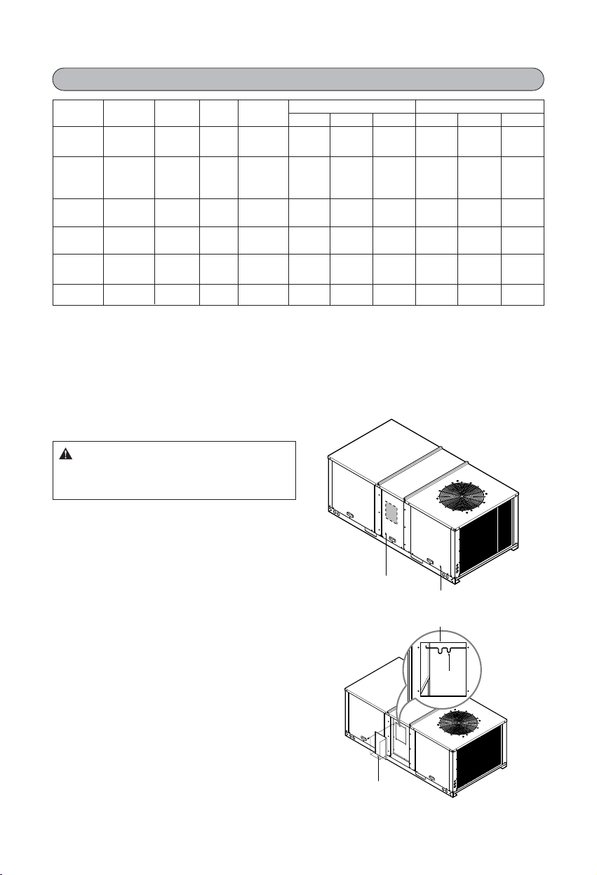
Installation
1. Loosen the screw that secures heater
compartment access panel. Lift up, pull
towards you and slide it down to remove.
2. Remove four(4) screws from block off panel
to expose heater cavity and heaterʼs back
support bracket. Save screws for installing
heater later.(See Figure 2.)
Heater Access Panel
Compressor Access Panel
Figure 1
Figure 2
: Open and lock unit disconnect
switch before installing this accessory to prevent
injury or death due to electrical shock or contact
with moving parts.
WARNING
Support
Bracket
Block off panel
Heater Cavity
Page 3

3
Heater and Control Box Assembly
3. Insert heater into the opening hole of heater
control box.
4. Align holes and secure screws to the control
box as shown in Figure 3.
Single Bank Heater Installation
-
LKAEH052, LKAEH102, LKAEH152,
LKAEH09B, LKAEH18B, LKAEH36BL
5. Place the heater control assembly in the
heater cavity.
6. Secure the heater control assembly of
heater cavity using four(4) screws. (See
Figure 4.)
Important: Make sure the heater arm slides
into heaterʼs back support bracket.
Two Bank Heaters Installation
-
LKAEH36B
7. For two heaters installation, align holes and
secure screws to the control box as shown
in Figure 3.
8. Secure the heater control assembly on
heater cavity using four(4) screws.(See
Figure 5)
Important: Make sure the heaterʼs arm slides
into heaterʼs back support bracket.
Heater Control Box
Heater
Figure 3
Figure 4
Figure 5
Page 4

9. Remove the nut, lock washer and flat
washer from heater terminal posts marked
L1, L2 and L3.
10. Connect wiring from control box panel to
the correct terminal post as shown on
heaterʼs wiring diagram.
Note: The correct sequence for replacing the
hardware on the heater terminal posts is: 1)
wire connector 2) flat washer 3) locking washer
4) nut. “DO NOT OVER TIGHTEN NUT ON
TERMINALS” use a nut driver only to tighten
connection.(See Figure 6.)
4
L3
L2
Figure 6
Control Wiring
11. Connect control wires(Brown) on terminal
block (and P.C.B) as shown on wiring
diagram attached on compressor access
panel.
Power Wiring
12. Then route wires down through the
opening in the top of control box. Connect
wires to high voltage terminal block. Refer
to wiring diagram supplied with heater.
13. Check to make certain the proper size
fuses are installed per the fuse table for
the exact heater being used.
14. Ground unit at the grounding lug
provided. Make sure all field wiring
complies with all applicable codes and
water tightness.(Figure 7)
15. Remove compressor panel, then remove
unitʼs control box cover. Connect high
voltage leads to bottom of compressor
contactor or terminal block.(See unitʼs
wiring diagram.) Replace control box
cover and access panel onto unit.
(Figure 7)
CAUTION: Use copper conductors only to
prevent equipment damage. Unit terminals
are not designed to accept any other wiring.
16. Replace control box cover using four(4)
screws.
17. Replace heater access panel.
CAUTION: Do not over tighten the nuts on the
heater terminals. if the nuts are over tightened
the ceramic insulators will break and heaters
must be replaced.
Maximum torque on nuts is 11 inch
pounds.
To Unit Control Box.
Ground
Power Supply
Terminal Block
Figure 7
 Loading...