

P/No.:3828A20128R
■ Follow the details to install the external cover correctly.
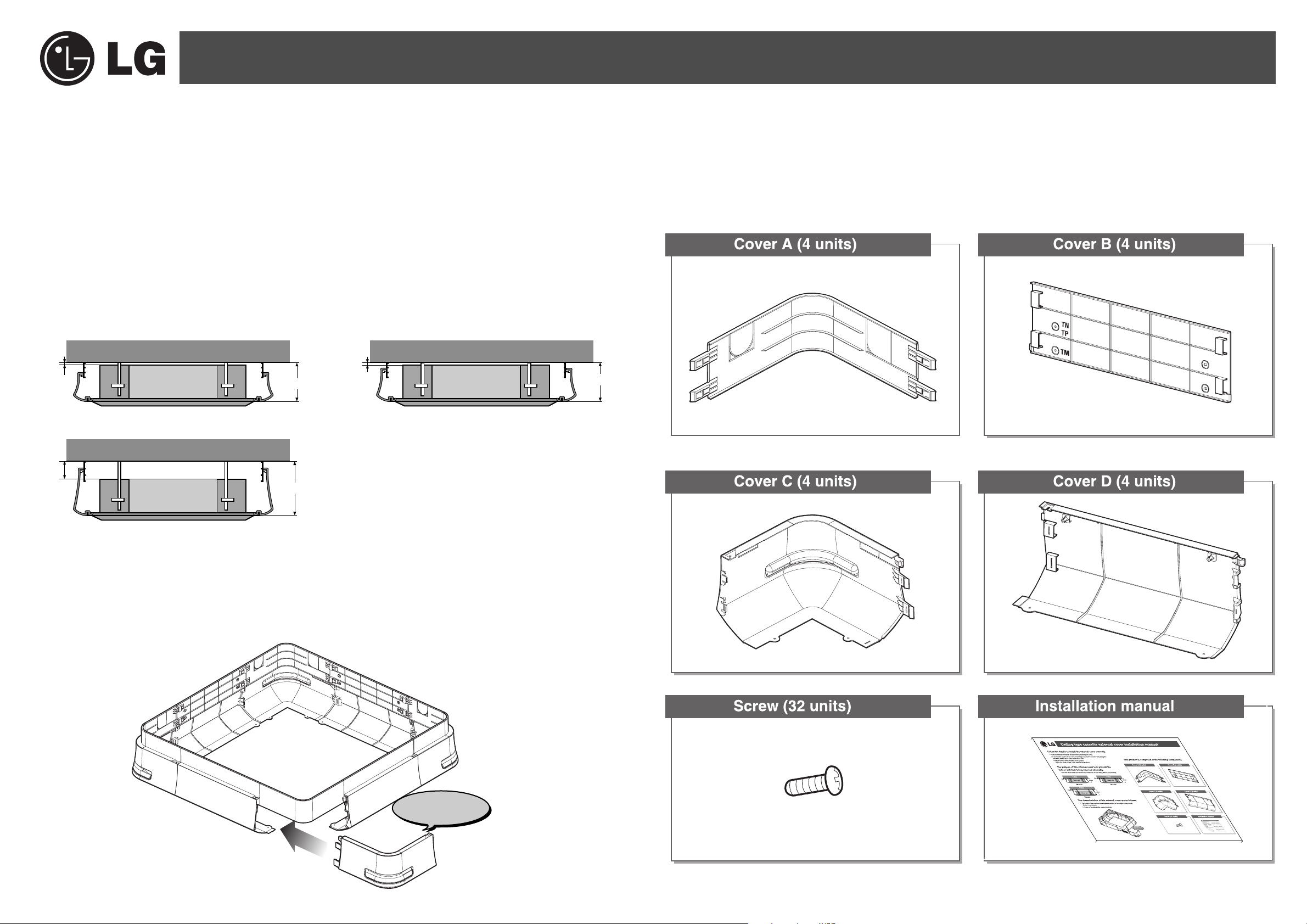
■ This product is composed of the following components.
• Read the installation manual carefully before installing the cover.
• To prevent the exterior of the cover from being scratched or become dirty during the
assembly, always put a clean sheet on the floor.
• Always use the screw included in the product.
(If you use other screws, it can damage the product.)
■ The characteristics of this external cover are as follows.
1. The height of the cover can be adjusted according to the height of the product.
(Refer to top picture)
2. Cover on the piping side can be detached.
■ The purpose of this external cover is to prevent the
indoor unit from being exposed externally.
• Use this when install the cassette air conditioner on the ceiling without any finishing.
8mm
50mm
8mm
Indoor unit
Ceiling
Indoor unit
Ceiling
Indoor unit
Ceiling
266mm
266mm
308mm
Detach function
TM model
TP model
TN model
Cassette cover installation manual
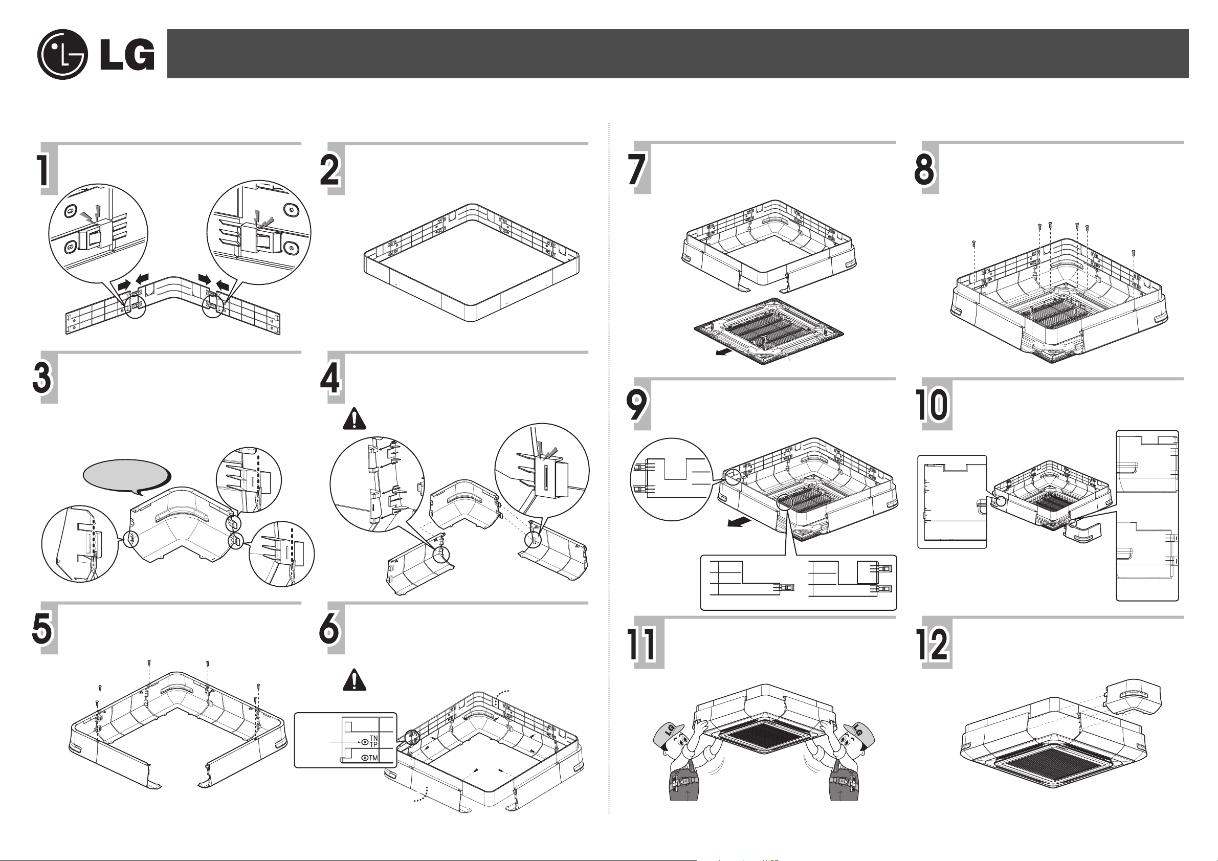
■ Installation order
P/No.:3828A20128R
Cassette cover installation manual
Assemble 4 covers A and 4 covers B as
shown in the picture.
Click
Click
Click
Cover B
Cover A
Cover B
Click
Take one of the 4 covers C and cut out 3
locations for assembly.
(Cut out by the groove on the assembly part.)
Complete the assembly until the
rectangular shape is formed as shown in
the picture.
Assemble the remaining 3 covers C and 4
covers D so that they form a rectangular
shape as shown in the picture.
Do not assemble one cover C of which the assembly part
is cut out so that it can be detached.
Click
Click
Check the direction of the front panel and
set the cover on the panel.
connecting wire is coming out is the same as the
location of the detachable cover.)
Direct where
the pipe is coming out
(The direction the
Connecting wire
After selecting the direction you want,
make holes for pipe and drain hose to fit
the installation environment.
Use the provided screws to assemble the
cover on the front panel. (14 locations)
Tighten 4 locations
Tighten 4 locations
For TN and TP model, drill a hole in
cover C as well.
Cut out only 1
cover C
Assemble using cover C and D as shown
in the picture and use the provided
screws to tighten the covers. (6 locations)
Drill a hole
before
tightening
the screw
Cover C
Cover D
Cover D
Set the assembled part with cover A and B,
and the assembled part with cover C and D to
the height of the indoor unit, and tighten the
screws. (8 locations)
For TN and TP, drill a hole before tightening
the screw.
Assembled part with
cover A and B
Cut when using
the drain hose
Direction where
the pipe is coming out
When using the pipe When using the drain hose
Hold the front panel while keeping it
leveled to assemble the indoor unit.
(Refer to product installation manual)
When using
the drain hose
Detachable cover
When using
the pipe
Assemble the detachable cover C.
Assembled part with
cover C and D
 Loading...