

Page 1
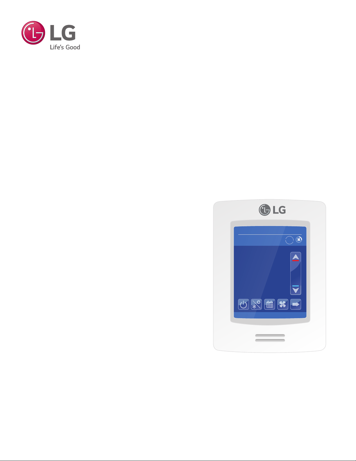
MultiSITE CRC1 Series Controllers
USER INTERFACE GUIDE
09-26-2017
Occ Auto Heat
Indoor °F
74°
Humidity
66 %
2:43 PM
Auto
78
68
PREMTBVC0 – MultiSITE CRC1
PREMTBVC1 – MultiSITE CRC1+
Page 2

PROPRIETARY DATA NOTICE
This document, as well as all reports, illustrations, data, information, and other
materials are the property of LG Electronics U.S.A., Inc., and are
disclosed by LG Electronics U.S.A., Inc., only in confidence.
Do not throw away, destroy, or lose this manual.
Please read carefully and store in a safe place for future reference.
Content familiarity required for proper installation and operation.
The instructions included in this manual must be followed to prevent prod-
uct malfunction, property damage, injury, or death to the user or other
people. Incorrect operation due to ignoring any instructions will cause
harm or damage. A summary of safety precautions begins on page 4.
For more technical materials such as submittals, engineering
databooks, and catalogs, visit www.lghvac.com.
UM_CRC1_Series_Controllers_05_17
For continual product development, LG Electronics U.S.A., Inc., reserves the right to change specifications without notice.
©LG Electronics U.S.A., Inc.
This document, as well as all reports, illustrations, data, information, and other materials are the property of LG Electronics U.S.A., Inc.
Page 3

TABLE OF CONTENTS
Safety Instructions ....................................................................................................... 4
Introduction .................................................................................................................. 7
MultiSITE CRC1 Series Controllers .........................................................7
Compatible Equipment .............................................................................7
Accessories ..............................................................................................7
Safety .......................................................................................................7
Controller Overview ..................................................................................................... 8
Home Screen ...........................................................................................8
Operation Mode .......................................................................................9
Adjusting Setpoints in Auto Mode ..........................................................10
Setpoint Adjustment ...............................................................................11
Using the Controller Conguration Screens ...........................................12
Conguration Screens ............................................................................................... 13
Schedule Screen ....................................................................................13
More Screens .........................................................................................15
Installer Conguration Screens ..............................................................17
Conguration Main Screens ...................................................................18
ZigBee Wireless System .................................................................19
Building Manager Screens ..............................................................20
Display/Date and Time Settings ................................................21
Customize Home View ..............................................................22
Filter Functions .........................................................................23
Setpoints Conguration .............................................................24
Override Setup ..........................................................................25
Setback Setup ...........................................................................26
Outdoor Unit Control .................................................................27
Installer ............................................................................................28
General Settings .......................................................................29
Temperature Settings ................................................................31
Fan Settings ..............................................................................32
Heat Settings ............................................................................33
Emergency Heater Settings ................................................34
Accessories ...............................................................................35
BMS Conguration ..........................................................................37
BACnet Settings ........................................................................37
ZigBee Conguration ................................................................39
Basic Diagnostic ..............................................................................42
Password Setup ..............................................................................45
Factory Default ................................................................................46
Relative Humidity Display ......................................................................47
Time and Date ........................................................................................47
PIR (Motion Sensor) ..............................................................................48
User Interface Guide
Due to our policy of continuous product innovation, some specifications may change without notification.
©LG Electronics U.S.A., Inc., Englewood Cliffs, NJ. All rights reserved. “LG” is a registered trademark of LG Corp.
3
Page 4
SAFETY INSTRUCTIONS
WARNING
DANGER
WARNING
CAUTION
DANGER
The instructions below must be followed to prevent product malfunction, property damage, injury or death to the user or other people. Incorrect operation due to ignoring any instructions will cause harm or damage. The level of seriousness is classified by the symbols below.
TABLE OF SYMBOLS
This symbol indicates an imminently hazardous situation which, if not avoided, will result in death or
serious injury.
This symbol indicates a potentially hazardous situation which, if not avoided, could result in death or
serious injury.
This symbol indicates a potentially hazardous situation which, if not avoided, may result in minor or
moderate injury.
Note:
Do not touch any exposed outdoor unit wiring, terminals, or other electrical components with tools or exposed skin. Only
qualied technicians should install, use or remove this unit.
Improper installation or use may result in re, explosion, electric shock, physical injury and/or death.
Don’t use or store ammable gas or combustibles near an outdoor or indoor unit.
There is risk of re, explosion, and physical injury or death.
The information in this manual is intended for use by a
MultiSITE CRC 1 Controller
trained technician familiar with the U.S. National Electric
Code (NEC) who is equipped with the proper tools and test
instruments.
Failure to carefully read and follow all instructions in this manual may
result in equipment malfunction, property damage, personal injury and/
or death.
Risk of electric shock. Disconnect all power before
servicing.
Do not install the MultiSITE Controller unit if it will be
exposed to rain or other precipitation.
Do not install the unit in a location exposed to open ame
or extreme heat.
Do not touch the unit with wet hands.
There is risk of re, electric shock, physical injury and/or death.
Replace all control box and panel covers.
If cover panels are not installed securely, dust, water and animals may
enter the unit, causing re, electric shock, and physical injury or death.
Wear protective gloves when handling equipment.
Sharp edges may cause personal injury.
This symbol indicates situations that may result in equipment or property damage accidents only.
This symbol indicates an action that should not be performed.
Dispose of any packing materials safely.
• Packing materials, such as nails and other metal or wooden parts
may cause puncture wounds or other injuries.
• Tear apart and throw away plastic packaging bags so that children
may not play with them and risk suffocation and death.
Do not change the settings of the protection devices.
If the pressure switch, thermal switch, or other protection device is
shorted and forced to operate improperly, or parts other than those
specied by LG are used, there is risk of re, electric shock, explosion,
and physical injury or death.
If the air conditioner is installed in a small space, take measures to prevent the refrigerant concentration from exceeding safety limits in the event of a refrigerant leak.
Consult the latest edition of ASHRAE (American Society of Heating,
Refrigerating, and Air Conditioning Engineers) Standard 15. If the re-
frigerant leaks and safety limits are exceeded, it could result in personal
injuries or death from oxygen depletion.
4
Due to our policy of continuous product innovation, some specifications may change without notification.
©LG Electronics U.S.A., Inc., Englewood Cliffs, NJ. All rights reserved. “LG” is a registered trademark of LG Corp.
Page 5
SAFETY INSTRUCTIONS
MultiSITE Controller is for use with select LG commercial air
conditioning systems only.
Do not attempt to use MultiSITE Controller with any other
type of system. Refer to the compatible equipment list in this
manual.
There is risk of equipment damage or degraded performance
Do not cut, lengthen or shorten the cable between the
MultiSITE Controller unit and the indoor unit.
Do not install the MultiSITE Controller unit in a location
where the cable cannot be safely and easily connected between the two units.
Do not allow strain on this cable.
There is risk of equipment damage.
Clean up the site after all procedures are nished, and check
that no metal scraps, screws, or bits of wiring have been left
inside or surrounding the controller or indoor units.
Provide power to the outdoor unit compressor crankcase
heaters at least six (6) hours before operation begins.
Starting operation with a cold compressor sump(s) may result in severe
bearing damage to the compressor(s). Keep the power switch on during
the operational season.
Do not block the indoor unit inlet or outlet.
Unit may malfunction.
Securely attach the electrical cover to the indoor unit. Non-
secured covers can result in re due to dust or water in the
service panel.
Do not allow water, dirt, or animals to enter the unit.
There is risk of unit failure or degraded performance.
Do not spill water or other liquid on the inside of the
indoor unit, especially on electrical components.
Do not drop the MultiSITE Controller unit into water. If the
unit is immersed in water or other liquid, contact your local
authorized LG distributor for support.
There is risk of unit failure or degraded performance.
User Interface Guide
Due to our policy of continuous product innovation, some specifications may change without notification.
©LG Electronics U.S.A., Inc., Englewood Cliffs, NJ. All rights reserved. “LG” is a registered trademark of LG Corp.
5
Page 6

MultiSITE CRC 1 Controller
6
Due to our policy of continuous product innovation, some specifications may change without notification.
©LG Electronics U.S.A., Inc., Englewood Cliffs, NJ. All rights reserved. “LG” is a registered trademark of LG Corp.
Page 7
MultiSITE CRC1 Series Controllers
WARNING
This manual describes how to use the LG MultiSITE Commercial
Remote Controllers (CRC) 1. There are two models of this controller:
• MultiSITE CRC1 (Model PREMTBVC0)
• MultiSITE CRC1+ (Model PREMTBVC1)
The two models are identical with the exception of two functions
included in the MultiSITE CRC1+ only:
• Motion sensor
• Humidity sensor
Compatible Equipment
MultiSITE CRC1 Controllers are compatible with LG Commercial
Air Conditioning indoor units (except PTAC units).
Do not attempt to use a MultiSITE CRC1 controller with any
other equipment.
INTRODUCTION
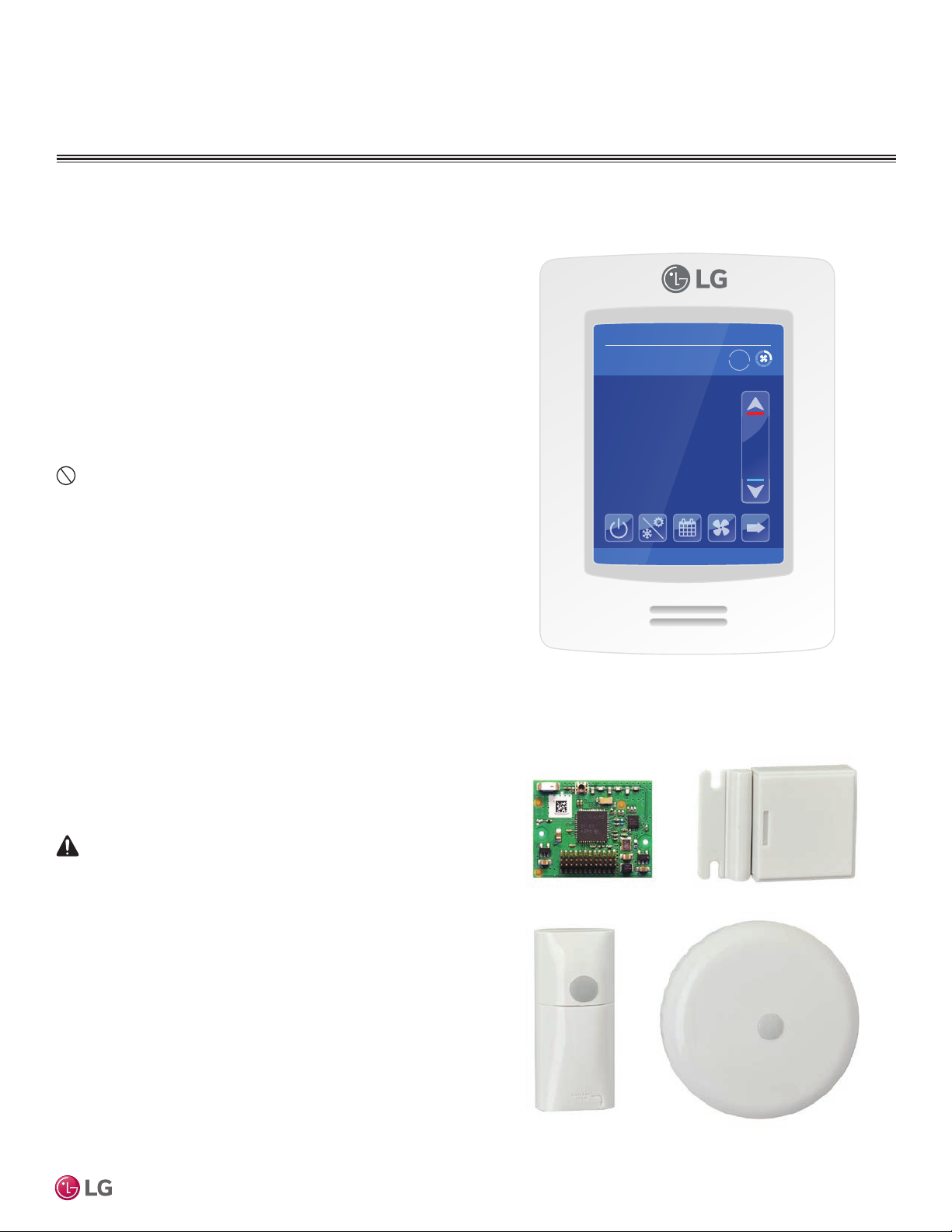
Typical MultiSITE CRC1 Controller
09-26-2017
Occ Auto Heat
Indoor °F
2:43 PM
Auto
78
74°
Humidity
66 %
68
User Interface Guide
Accessories
These accessories are available for MultiSITE CRC1 controllers:
• ZigBee® Pro wireless card Model ZVRCZPWC1
• Door and window switch Model ZVRCZDWS1
• Wall mounted occupancy sensor Model ZVRCZWOC1
• Ceiling mounted occupancy sensor Model ZVRCZCOC1
The ZigBee® Pro wireless card is required for communication
between the controller and the other accessories.
Safety
Safety of personnel is the primary concern during all procedures.
Read and understand the safety summary at the front of this manual.
Ensure the controller is installed in accordance with the appropriate
LG installation manual.
If troubleshooting is required, it must be performed by trained personnel
and in accordance with national wiring standards and all local or other
applicable codes. Improper troubleshooting and repair/replacement of
equipment can result in re, electric shock, physical injury, or death.
Note:
Improper troubleshooting and repair/replacement of equipment can
result in damaged equipment or degraded operation.
MultiSITE CRC1 Controller Accessories
ZigBee® Pro Wireless Card Door/Window Switch
*ZigBee is a registered trademark of the ZigBee Alliance.
Due to our policy of continuous product innovation, some specifications may change without notification.
©LG Electronics U.S.A., Inc., Englewood Cliffs, NJ. All rights reserved. “LG” is a registered trademark of LG Corp.
Wall Mounted
Occupancy Sensor
Ceiling Mounted
Occupancy Sensor
7
Page 8
CONTROLLER OVERVIEW
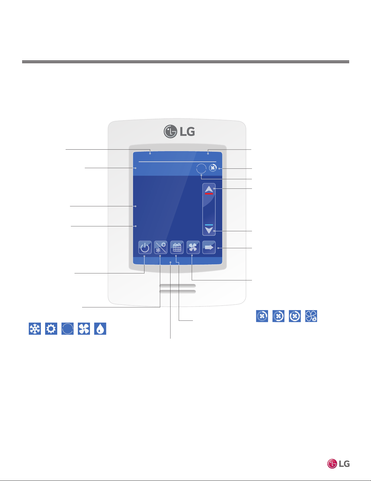
Home Screen
The controller home screen is shown and described below.
Current Date
2:43 PM
Auto
Occupancy Status
Occupied (Occ) or
Unoccupied (Unocc)
09-26-2017
Occ Auto Heat
Indoor °F
78
Room Indoor
Temperature
Room Indoor
Humidity
74°
Humidity
66 %
Locked by central controller
68
On/Off
Turn the display
on or off
MultiSITE CRC 1 Controller
Operation Mode
Set Cool, Heat, Auto
Cool, Auto Heat,
Fan, Dry modes
Auto
Note: Pressing and holding the
Operation Mode icon takes the user
to the Operation Mode page.
Short Network Message
Note:
Available functions/features may differ based on the connected system.
When any change is made to a parameter, the value is automatically saved in memory when the next
parameter is selected or another page is opened.
Arrows auto-increment/decrement at higher speed when holding button for more than 2.5 seconds.
Schedule
Set weekly
schedule
Current Time
Current Fan Speed Setting
Operation Mode Status
Up Arrow
Raise Temperature Setpoint
Down Arrow
Lower Temperature Setpoint
More
Provides end user with
access to less often used
functions.
Fan Speed
Set fan to Slow, Low, Low-Med,
Medium, Med-High, High, Power,
Auto. (Available options depend
on IDU model.)
Note: Long-press of the Fan
Speed button when in cooling
mode triggers Power Cooling
mode. If in Power Cooling mode,
last airow segment on top is lit
in purple and the text changes
from “Fan” to “Power Cool”. This
mode lasts for 30 minutes and
then reverts back to the previous
fan speed.
8
Due to our policy of continuous product innovation, some specifications may change without notification.
©LG Electronics U.S.A., Inc., Englewood Cliffs, NJ. All rights reserved. “LG” is a registered trademark of LG Corp.
Page 9
CONTROLLER OVERVIEW
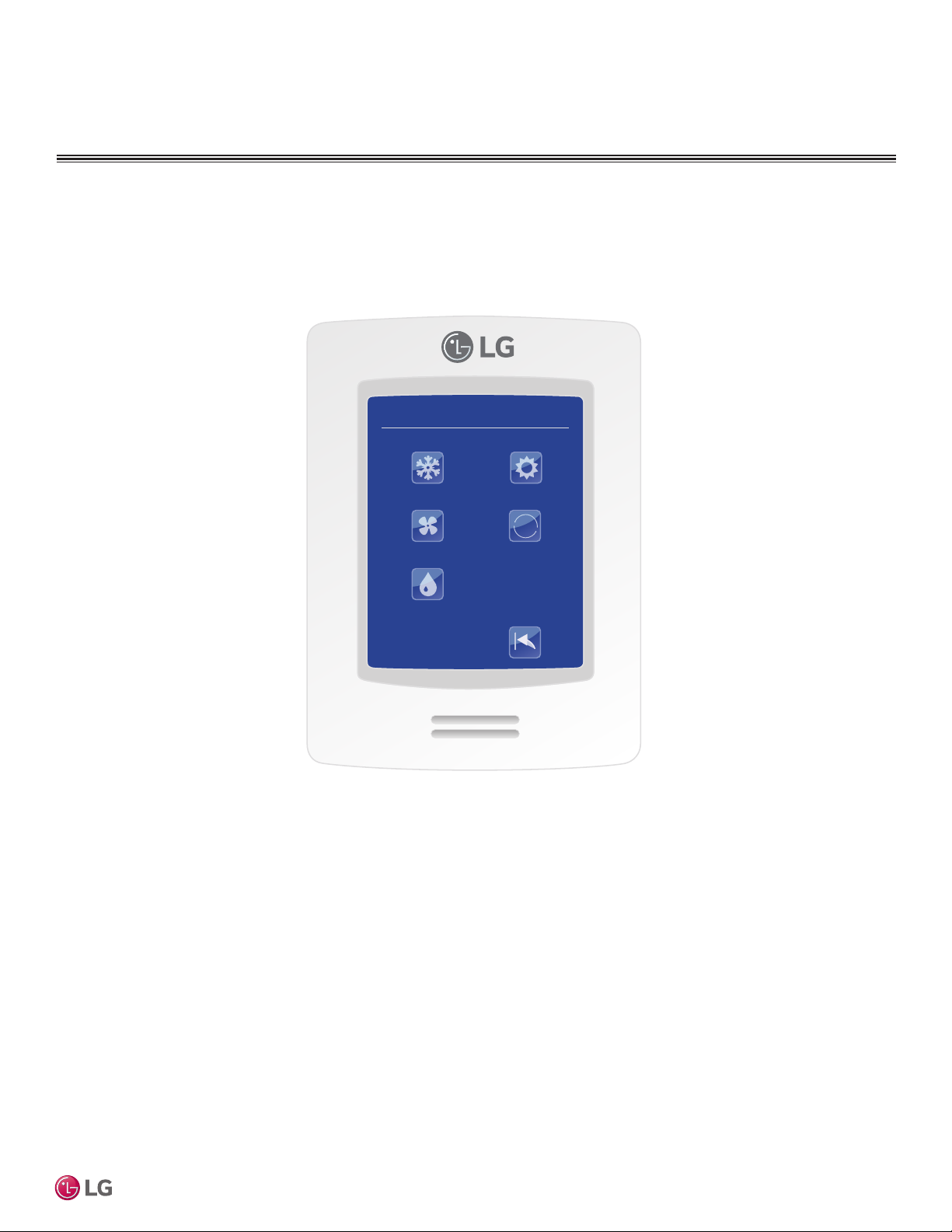
Operation Mode
Selecting modes available on this screen places the IDU in that mode and then the user will be returned
to the home screen. Selecting the mode that is currently highlighted will maintain the current mode and
return the user to the home screen.
OPERATION MODE
Cool
Fan
Dry
Heat
Auto
Auto
Setback
User Interface Guide
Due to our policy of continuous product innovation, some specifications may change without notification.
©LG Electronics U.S.A., Inc., Englewood Cliffs, NJ. All rights reserved. “LG” is a registered trademark of LG Corp.
9
Page 10
CONTROLLER OVERVIEW
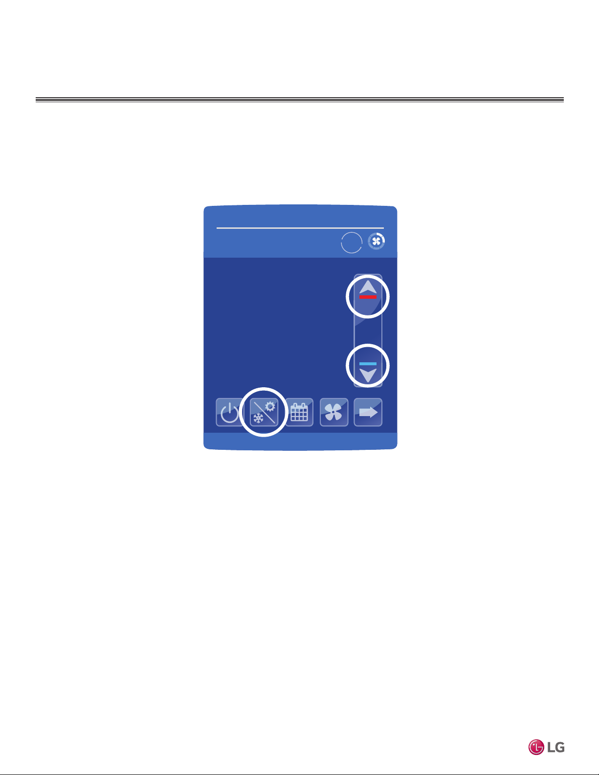
Adjusting Setpoints in Auto Mode
Setpoints can be modied in three different ways when in Auto Mode: Cooling Setpoint change, Heating Setpoint change, or
Cooling/Heating Setpoint change.
09-26-2017
Occ Auto Heat
2:43 PM
Auto
Indoor °F
78
74°
Humidity
66 %
MultiSITE CRC 1 Controller
Auto Mode, Cooling Cycle, Cooling Setpoint (Dual Setpoint setting)
When in cooling cycle of Auto Mode, use the up and down arrows to raise or lower the cooling setpoint.
When the setpoint is modified it will increase or decrease the difference between the cooling and heating setpoint values. The minimum difference allowed between cooling and heating setpoints is determined
by the Deadband control value setting (found in the Setpoint Config screen). "Cooling Setpoint" shows as
indicated on the screen to the left.
Auto Mode, Cooling Cycle, Heating Setpoint (Dual Setpoint setting)
To change the heating setpoint when in Auto Mode, cooling cycle, tap the up or down arrows to place the
controller into set point configuration mode and then immediately tap the Mode button once to change to
heating set point mode. "Heating Setpoint" shows when this parameter is set. Immediately move back to the
set point up or down arrows to change the heating set point.
Auto Mode, Cooling Cycle, Cooling/Heating Setpoint (Dual Setpoint setting)
To change the cooling and heating setpoints simultaneously, a third option is available for adjusting setpoints. If in Auto Mode (either cooling or heating cycle), tap either the up or down set point buttons, then
immediately tap the Mode button until “Cool/Heat” shows, indicating that the controller is in the correct set
point mode. Immediately move back to the up or down set point buttons to change the set points as desired.
68
10
Due to our policy of continuous product innovation, some specifications may change without notification.
©LG Electronics U.S.A., Inc., Englewood Cliffs, NJ. All rights reserved. “LG” is a registered trademark of LG Corp.
Page 11
CONTROLLER OVERVIEW
09-26-2017
2:43 PM
Occ Auto Heat
74°
Indoor °F
Humidity
66 %
Auto
78
68
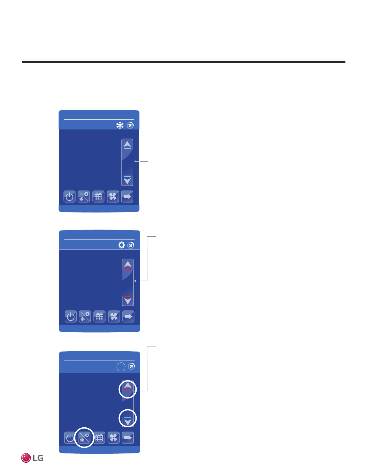
Setpoint Adjustment
Setpoints can be modied in three different ways when in Auto Mode; Cooling Setpoint change, Heating Setpoint change or
Cooling/Heating Setpoint change.
09-26-2017
Occ Auto Cool
Cooling Setpoint °F
74°
Humidity
45 %
09-26-2017
Occ Auto Heat
Heating Setpoint °F
74°
Humidity
45 %
2:43 PM
75.0
2:43 PM
75.0
Cooling mode or cooling only
sequence of operation
In Cooling mode, the setpoint displayed in the bar is the current occupied cooling setpoint.
During occupied setpoint adjustment, the large digits are temporarily used to display the occupied cooling setpoint while it
is adjusted.
Normal temperature display resumes after the setpoint is
adjusted and the actual occupied cooling setpoint is displayed
in the setpoint bar.
Heating mode or heating only
sequence of operation
In Heating mode, the setpoint displayed in the bar is the current occupied heating setpoint.
During occupied setpoint adjustment, the large digits are temporarily used to display the occupied heating setpoint.
Normal temperature display resumes after the setpoint is
adjusted and the actual occupied heating setpoint is displayed
in the setpoint bar.
User Interface Guide
Automatic Heating / Cooling mode
In automatic mode, the setpoint displayed at the top of
the set point bar represents the actual occupied cooling
setpoint.
During occupied setpoints adjustment, the large digits are
temporarily used to display the occupied “Cooling Setpoint” or occupied “Heating Setpoint”. The actual setpoint
is dependent on the last effective demand (heating or
cooling).
Normal temperature display resumes after the setpoints
are adjusted and the actual occupied heating and cooling
setpoints are displayed in the setpoint bar.
Due to our policy of continuous product innovation, some specifications may change without notification.
©LG Electronics U.S.A., Inc., Englewood Cliffs, NJ. All rights reserved. “LG” is a registered trademark of LG Corp.
11
Page 12
CONTROLLER OVERVIEW
1/3 Zigbee Configuration
Zigbee channel
Zigbee PAN ID
COM address
15
11
254
Zigbee short
0x0000
Node type
Zigbee status
No NWK
Coord.
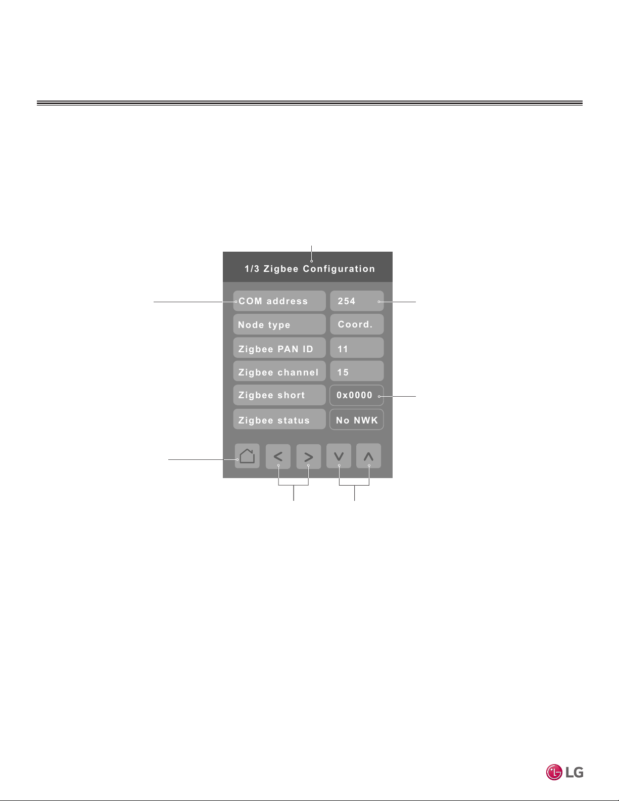
Using the Controller Configuration Screens
Some of the buttons on the Home screen display conguration screens. Controller operating parameters can be set as necessary for your system. The gure below describes how to use the conguration
screens.
Screen Name
Controls
The left side of the
screen lists controls and
monitored parameters.
Back Button
Tapping this button
MultiSITE CRC 1 Controller
goes back one level in
the screen hierarchy.
Left/Right Arrows
The left and right
arrows move between
screens on the same
level as the currentlydisplayed screen.
Control Values
The right side of the
screen is a button you
can tap to change the
value of the control or
parameter displayed to
its left.
Read Only
Dark gray buttons are
read only. These values
can’t be changed by the
user.
Up/Down Arrows
The up and down
arrows are used to
change the value of
the active (highlighted)
control.
12
Due to our policy of continuous product innovation, some specifications may change without notification.
©LG Electronics U.S.A., Inc., Englewood Cliffs, NJ. All rights reserved. “LG” is a registered trademark of LG Corp.
Page 13
CONFIGURATION SCREENS
--:--
--:--
****day S c h edule
--:--
Delete
--:--
--:--
Copy t o
74°F
70°F
Monday 06:00 AM
Setpoint cool
Setpoint heat
Heat
System mode
Fan speed
Occ. / Unocc.
Medium
Occupied
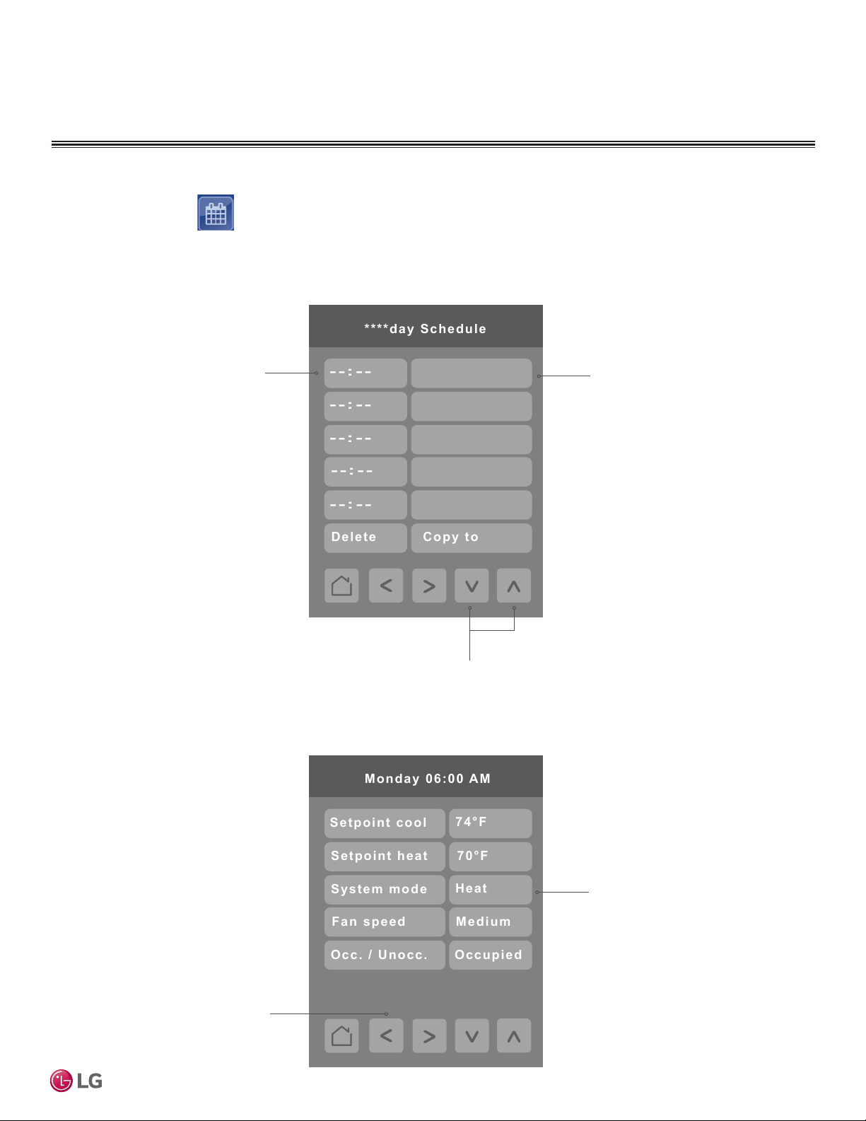
Schedule Screen
Press the Schedule button on the Home screen to display the Schedule Screen. There are different
schedule setting screens, one for each day of the week (7 days) titled accordingly. Each can have different
scheduled events where the room controller is set for set point, system mode, fan speed and occupancy
status. Five (5) separate events can be configured per day.
Tap the left-hand button to set
the time for scheduled event.
When the time for a new event
Tap the right-hand side button
to enter the next screen.
is configured, the default system mode of “Off” will appear
in the event overview portion of
the control on the right side.
Adjust the time in the left column by pressing on the
Up and Down arrows. To configure the System mode
for the time selected tap on the right column.
This typical schedule screen shows the parameters that can be adjusted for a specific time and day in a week.
User Interface Guide
Once the event has been fully
configured, press the left arrow to be returned to the daily
schedule overview screen.
Due to our policy of continuous product innovation, some specifications may change without notification.
©LG Electronics U.S.A., Inc., Englewood Cliffs, NJ. All rights reserved. “LG” is a registered trademark of LG Corp.
Up to 5 separate events per day can
be configured. User can set cooling
and heating set points, system mode
(Off, Dry, Cool, Heat, Fan and Auto),
fan speed and Occupied/Unoccupied
status.
13
Page 14
CONFIGURATION SCREENS
06:00AM
05:00PM
Monday S c h edule
H 74 / 70:O
C 71 / 69:U
Of f
--:--
--:--
09:00PM
Copy t o
Delete
Copy to day(s)
Monday
Tuesday
Wednesday
Friday
Sunday
Thursday
Saturday
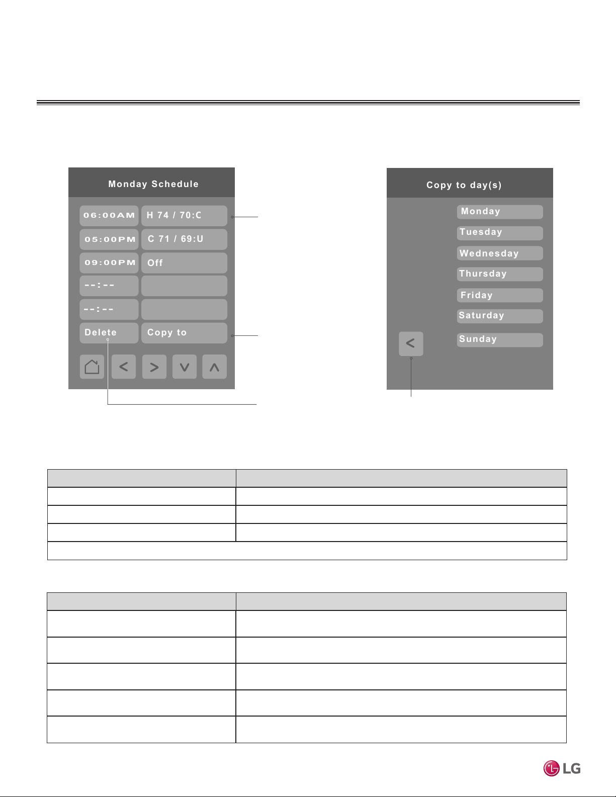
Daily Schedule Screens – continued
To modify an existing
event, tap either the
left side control to
edit the time or tap
H 74 / 70:O
the right-hand side of
the control to re-enter
the event screen and
make your desired
changes.
If desired, use the
'Copy to' button to
copy the schedule
to another day of
the week. First
choose the time of
the event you want
to copy and then
choose ‘Copy to’.
MultiSITE CRC 1 Controller
Event Overview Display Parameter Meaning
First Letter Mode (O=off, C=cool, H=heat, F=fan, A=auto, D=dry)
Second Number(s) Set Point(s)
Third Letter Occupancy Status (U=unoccupied, O=Occupied)
Example: H: 74 / 70: O = Heating Mode, Upper setpoint of 74, Lower setpoint of 70, Occupied
Conguration Parameters Default Value Parameter Settings
Setpoint cool
Default value: 78°F
Setpoint heat
Default value: 68°F
System mode
Default value: OFF
Fan Speed
Default value: Low
Occ./Unocc.
Default value: Unoccupied
To delete an event,
tap the time of the
event and then tap
the Delete button.
Choose the day(s)
you want to copy the
event to and then
press the left arrow.
Range: 52-99 °F
Range: 40-90 °F
Choices: Off, Cool, Heat, Fan, Auto, Dry
Choices: Slow, Low, Low-Med, Medium, Med-High, High, Power, Auto
Choice: Unoccupied, Occupied
14
Due to our policy of continuous product innovation, some specifications may change without notification.
©LG Electronics U.S.A., Inc., Englewood Cliffs, NJ. All rights reserved. “LG” is a registered trademark of LG Corp.
Page 15
CONFIGURATION SCREENS
English
More
Language
°F(1)
Temp Units(12)
Off
Outside Air - Vent.
Off
Plasma Purifier
On
Aux Heat
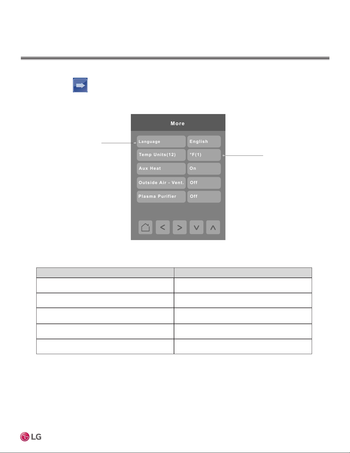
More Screens
Press the More button on the Home screen to display the More screen.
Language
Use the up and down
arrows to switch
between English, French
and Spanish
Temp Units
Allows you to switch
between Celsius and
Fahrenheit
User Interface Guide
Language
Default value: English
Temp Units - °F/°C (12)
Default value: °F
Aux Heat
Default value: Off
Outside Air - Vent.
Default value: Off
Plasma Purifier
Default value: Off
Conguration Parameters Default Value Parameter Settings
Choices: English, French, Spanish
Choices: 0 = “°C (0)”, 1 = “°F (1)”
Choices: 0 = “Off”, 1 = “On”
Choices: 0 = “Off”, 1 = “On”
Choices: 0 = “Off”, 1 = “On”
Due to our policy of continuous product innovation, some specifications may change without notification.
©LG Electronics U.S.A., Inc., Englewood Cliffs, NJ. All rights reserved. “LG” is a registered trademark of LG Corp.
15
Page 16
CONFIGURATION SCREENS
Off(0)
Vane Direction
Airflow Up/Down
Off(0)
Airflow Left/Right
Off(0)
Airflow Circular
Va n e Fixed A ngle
More Screens – continued
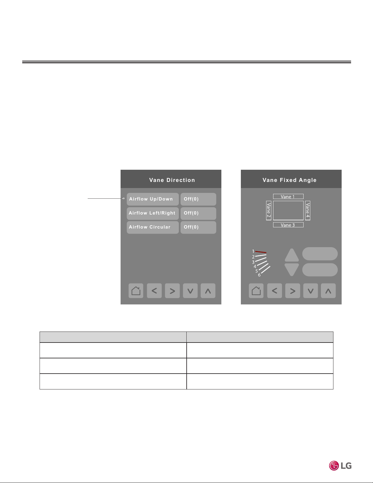
Press the right arrow button to display these screens. To adjust vane angle, user selects vane(s) by tapping
vane icon at the top of the screen, adjusts vane angle by using up/down arrows and then selects Apply button.
Note:
Vane xed angle control for multi-vane systems occurs in pairs. Refer to the Vane Fixed Angle screen. If a 4-louver
device is identied, when the user chooses Vane 1 or Vane 3 control, the opposite vane (Vane 3 or Vane 1) will be
controlled at the same time. If Vane 2 or Vane 4 is selected, Vane 4 or Vane 2 will be controlled in lockstep with its
matching pair as well. The same control behavior holds for a 2-louver device.
Airflow Up / Down and
Airflow Left / Right con-
trols can both be “On” at
the same time. However,
when Airflow Circular
control is “On,” both of
the other two controls will
be set to “Off.”
ALL
MultiSITE CRC 1 Controller
Conguration Parameters Default Value Parameter Settings
Airow Up / Down
Default value: Off
Airow Left / Right
Default value: Off
Airow Circular
Default value: Off
Apply
Default
Choices: 0 = “Off”, 1 = “On”
Choices: 0 = “Off”, 1 = “On”
Choices: 0 = “Off”, 1 = “On”
16
Due to our policy of continuous product innovation, some specifications may change without notification.
©LG Electronics U.S.A., Inc., Englewood Cliffs, NJ. All rights reserved. “LG” is a registered trademark of LG Corp.
Page 17
CONFIGURATION SCREENS
Installer Configuration Screens
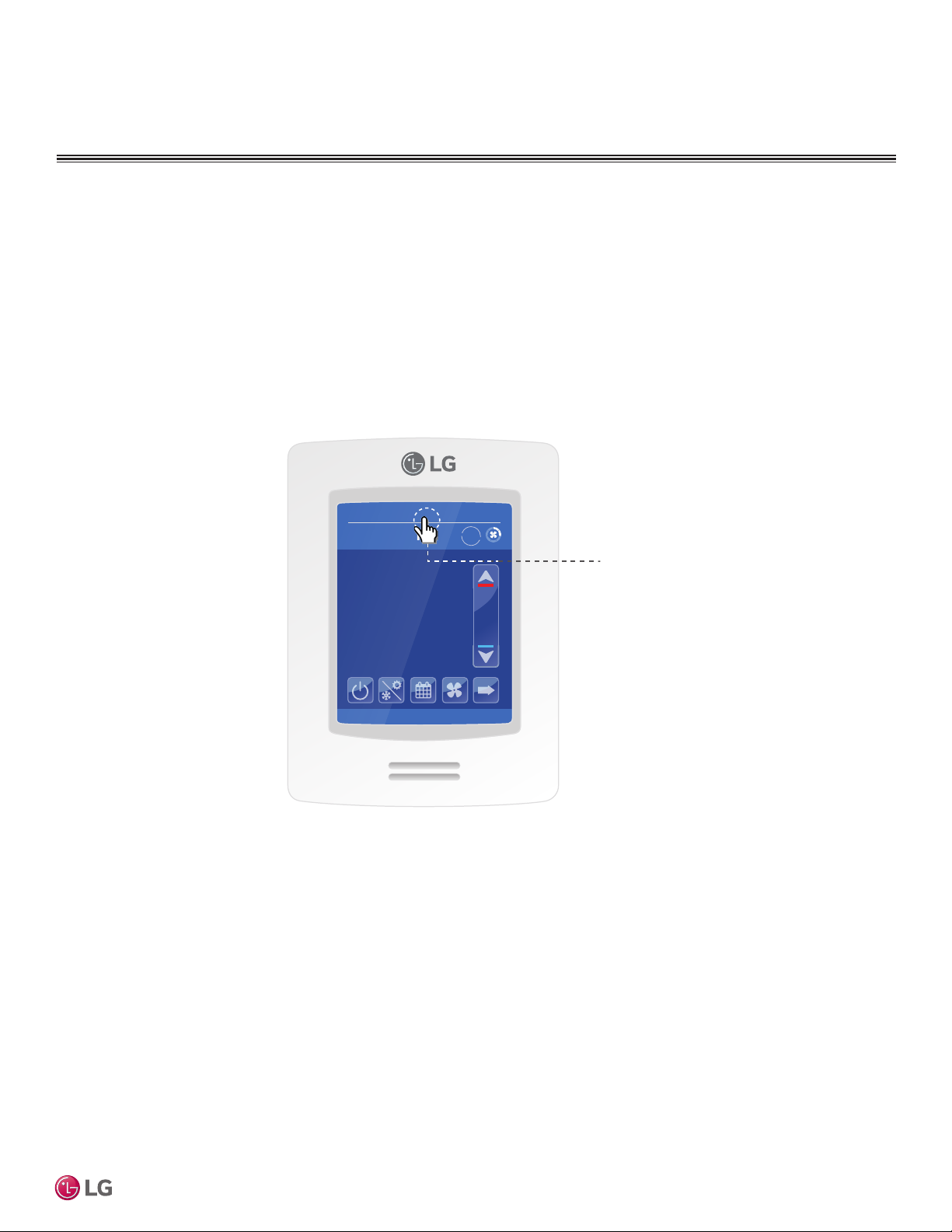
These screens are more commonly used during installation, system configuration, or troubleshooting than
by an end user. There is no icon on the Home screen to access these configuration screens. You must press
and hold the area of the screen indicated on the diagram below to access the first screen.
If a configuration / installer password is activated to prevent unauthorized access to the configuration menu
parameters, a password entry prompt will appear to prevent access to the device configuration components.
09-26-2017
Occ Auto Heat
Indoor °F
74°
Humidity
66 %
2:43 PM
Auto
78
68
User Interface Guide
Touch and hold here
for 3 seconds to enter
conguration mode.
Due to our policy of continuous product innovation, some specifications may change without notification.
©LG Electronics U.S.A., Inc., Englewood Cliffs, NJ. All rights reserved. “LG” is a registered trademark of LG Corp.
17
Page 18
CONFIGURATION SCREENS
Configuration Main Screens
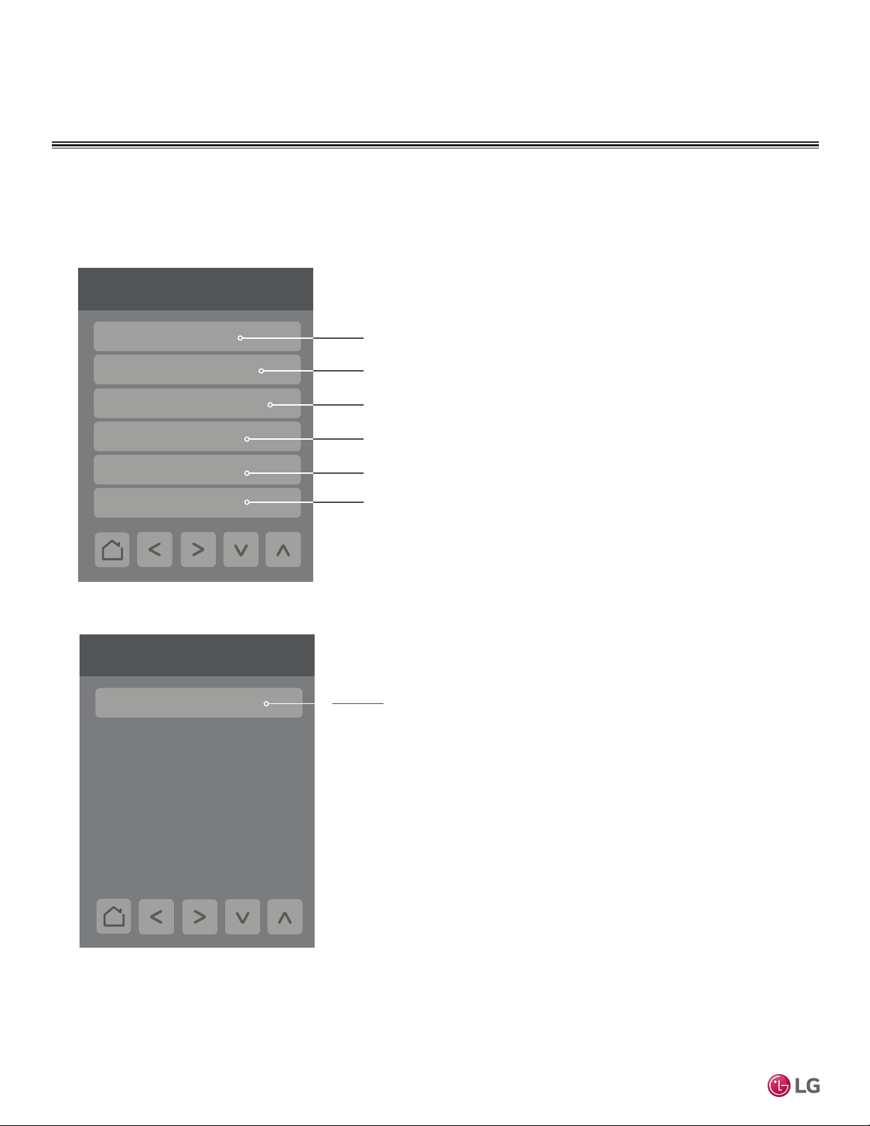
There are two main configuration screens as shown below. Press the left and right arrow buttons to move
between these two screens. Press a button on a screen to display the parameter selections for that item.
Configuration 1/2
Enter Display, Date & Time, Filter, Setpoints, Override,
Building Manager
Setback and Outdoor Unit configuration
Installer
BMS Config
Basic Diagnostic
Password Setup
Factory Default
Configuration 2/2
MultiSITE CRC 1 Controller
Wireless Ecosystem
Enter General, Temperature, Fan and Heat settings and
Accessories configuration
Enter BACnet settings
View Diagnostic parameters
Setup a password to restrict/allow access to the thermostat
Reverts all controller control settings back to default values.
Note: User will be given the option to conrm that they wish to
proceed. Once in the Factory Default screen, if user proceeds with
this step, all schedules and current controller settings, along with time
and date will be cleared. There is no way to recover settings once a
Factory Default has been performed.
Enter ZigBee wireless zone configuration settings.
18
Due to our policy of continuous product innovation, some specifications may change without notification.
©LG Electronics U.S.A., Inc., Englewood Cliffs, NJ. All rights reserved. “LG” is a registered trademark of LG Corp.
Page 19
CONFIGURATION SCREENS
Set function to
Status
1/10 Zone
Battery
No
Paired
0x0000
IEEE addr.
None
Closed
Normal
Permit join
On
Set function to
Status
10/10 Zone
Battery
No
Paired
0x0000
IEEE addr.
None
Closed
Normal
ZigBee Wireless System
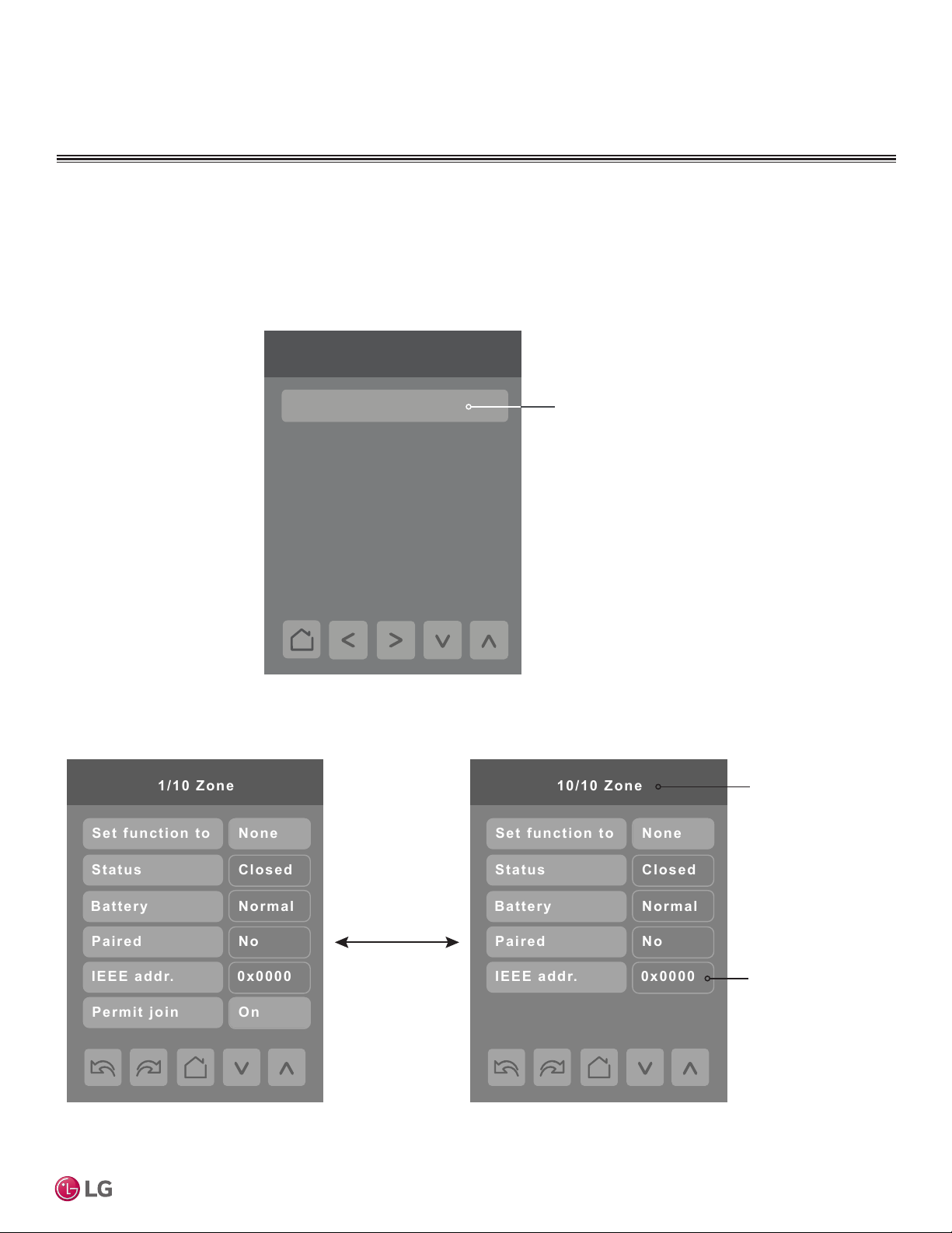
When ZigBee wireless sensors are set up to communicate with the controller, the functioning of each
such sensor is described in a separate Zone screen, up to a maximum of 10 Zones. Press the left and
right arrow keys to move between Zone screens. Select the appropriate type of sensor using the up
and down arrow keys.
Configuration 2/2
Wireless Ecosystem
Enter ZigBee wireless Zone
configuration settings.
User Interface Guide
Up to 10 separate
wireless sensors
can be configured,
each with its own
Zone screen
Due to our policy of continuous product innovation, some specifications may change without notification.
©LG Electronics U.S.A., Inc., Englewood Cliffs, NJ. All rights reserved. “LG” is a registered trademark of LG Corp.
Only last 4 digits
in HEX shown
19
Page 20
CONFIGURATION SCREENS
1/2 Building Manager
Display / Date & Time
Customize Home View
Filter Functions
Setpoint Config.
1
Code Search
2/2 Building Manager
Outdoor Unit Control
Override Setup
Setback Setup
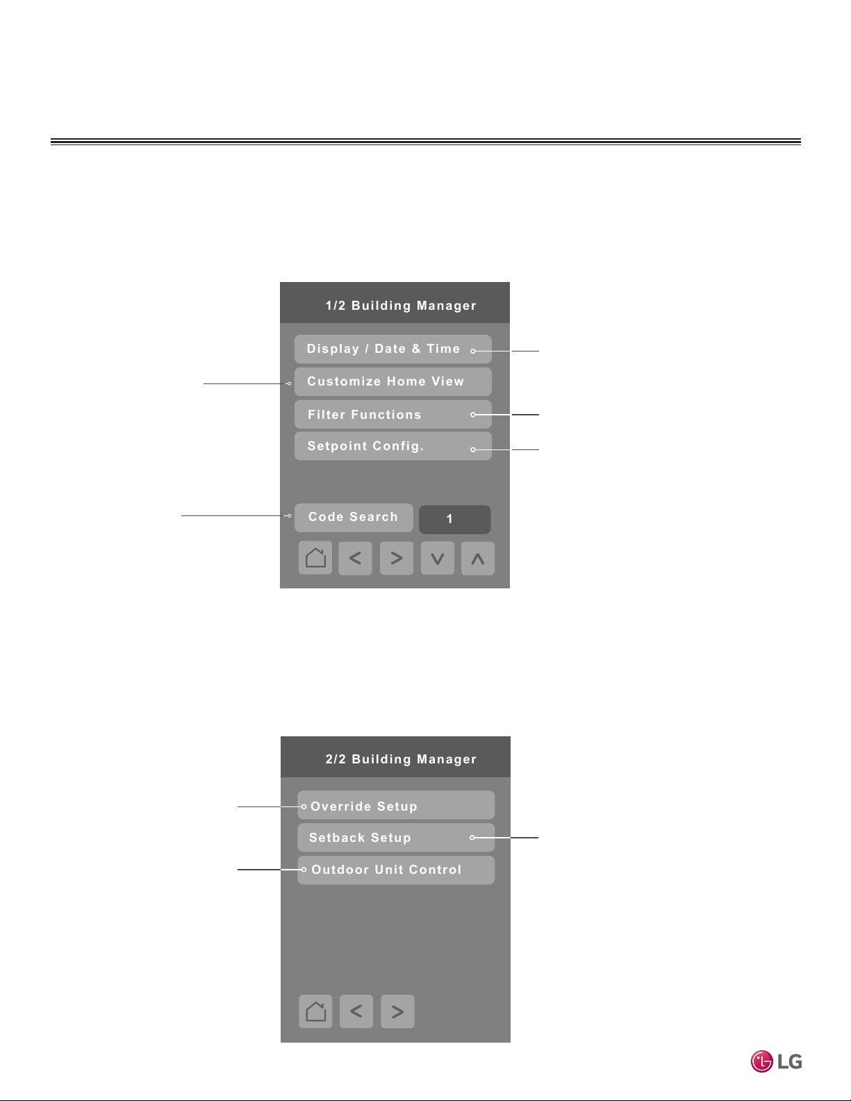
Building Manager Screens
There are two main configuration screens as shown below. Press the left and right arrow buttons to move
between these two screens. Press a button on a screen to display the parameter selections for that item.
Customize Home View
Hide On/Off, Mode, Schedule,
More, Set Temp, Space Temp,
Fan and Humidity options on
home screen.
Code Search
Use the Up and Down arrows
to choose an available
Function Code and select the
Code Search button to navigate to the screen where that
function code resides.
Codes can be found in
brackets next to a parameter
throughout all menus. This
function is used for quicker
MultiSITE CRC 1 Controller
menu navigation.
Display Basic Settings – Date / Time,
Display Color, Standby Brightness (and
delay timing), Night Backlight level, Standby
Screen).
Filter Functions – Clear Filter Alarm,
Remaining Time, Lower/Raise Grill, Robot
Cleaning
Setpoint Cong.
Choose between Single/Dual set point(s)
and congure set point max/min limits and
deadband.
Note: Available functions/features may differ
based on the connected system.
Override Setup
If controller is in the unoccupied mode then the controller
enters Override mode as soon
as the user taps the screen the
rst time.
Select this control to congure
settings for Override, including
set points, system mode, fan
speed and duration of override.
Outdoor Unit Control
Manage outdoor unit functions
through the Controller’s
interface.
20
Setback Setup
Setback settings are congurable
with this control including set
points, system mode and fan
speed.
Due to our policy of continuous product innovation, some specifications may change without notification.
©LG Electronics U.S.A., Inc., Englewood Cliffs, NJ. All rights reserved. “LG” is a registered trademark of LG Corp.
Page 21
CONFIGURATION SCREENS
Green
-5
60%
Display
Color
Standby screen
Contrast
Low backlight
No
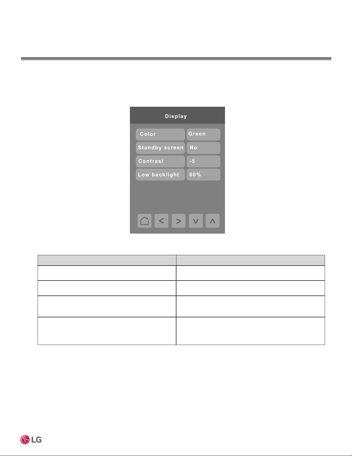
Display/Date and Time Settings
Press the Display / Date & Time button on the Building Manager screen to show the Display menu screen.
Press the right arrow button on the Display menu screen to show the Date & Time screen.
User Interface Guide
Conguration Parameters Default Value Parameter Settings
Color
Default value: White
Standby Screen
Default value: No
Contrast
Default value: -5
Low backlight
Default value: 60%
Choices: Blue, Green, Grey, Dark Grey, White
N/A
Display Contrast
Set contrast of display by using the up and down arrows.
Adjustable: -5 to 5.
Backlight Display
Set display backlight intensity after 2 minutes of
keyboard inactivity.
Adjustable: 0 to 100%.
Due to our policy of continuous product innovation, some specifications may change without notification.
©LG Electronics U.S.A., Inc., Englewood Cliffs, NJ. All rights reserved. “LG” is a registered trademark of LG Corp.
21
Page 22
CONFIGURATION SCREENS
AM-PM
2016
June
17
Date & T i me
Time f o rmat
Tim e
Year
Mont h
Day
11:55 A M
Fr ida y
Weekda y
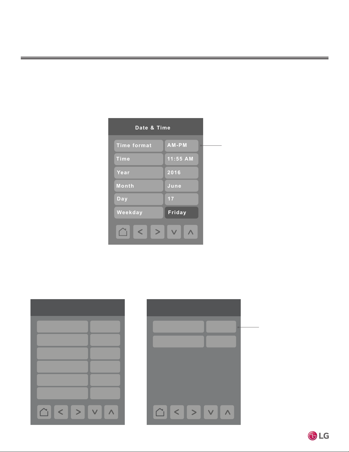
Display/Date and Time Settings – continued
Press the right arrow button on the Display screen to show the screen below. The Clock settings screen allows the device’s internal time settings to be changed, including current time, standard day, month, year and
weekday options, as well as the choice between a 12 hour AM / PM display or a 24 hour display. Using the
Up and Down arrows adjust the Time, Year, Month and Day parameters. The Weekday is automatically filled
by the system and it cannot be adjusted.
Select between a 12 or
24-hour format.
Customize Home View
Press the Customize Home View button on the Building Manager Screen to select the Hide Controls menu
MultiSITE CRC 1 Controller
screen. The Hide Controls menu is used to select which parameters are displayed on the home screen of
the thermostat. You can select which parameter to show or hide by tapping it and then using the Up and
Down arrows. By default, all parameters are shown on the main screen.
1/2 Hide Controls
On / Off Show
Mode Show
Schedule Show
More Show
Set Temp Show
Space Temp Show
2/2 Hide Controls
Fan Speed Show
Humidity Show
Select between the
Show and Hide options.
22
Due to our policy of continuous product innovation, some specifications may change without notification.
©LG Electronics U.S.A., Inc., Englewood Cliffs, NJ. All rights reserved. “LG” is a registered trademark of LG Corp.
Page 23
CONFIGURATION SCREENS
Filter Functions
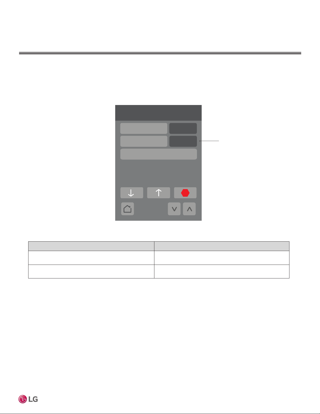
Press the Filter Functions button on the Building Manager screen to display the Filter Functions screen. The
Filter Functions menu displays the time and alarm parameters. These cannot be adjusted by the user.
Filter Functions
Conguration Parameters Default Value Parameter Settings
Filter Remain (Hrs)
Default value = N/A
Filter Alarm
Default value = N/A
Filter Remain(Hrs)
Filter Alarm
Clear Filter Alarm
Lower/Raise Grill
Range is: 2400 - 0
“Filter OK”
“Service Fltr!”
108
108
Filter OK
The time is measured in hours.
Maximum value is 2400.
User Interface Guide
Due to our policy of continuous product innovation, some specifications may change without notification.
©LG Electronics U.S.A., Inc., Englewood Cliffs, NJ. All rights reserved. “LG” is a registered trademark of LG Corp.
23
Page 24
CONFIGURATION SCREENS
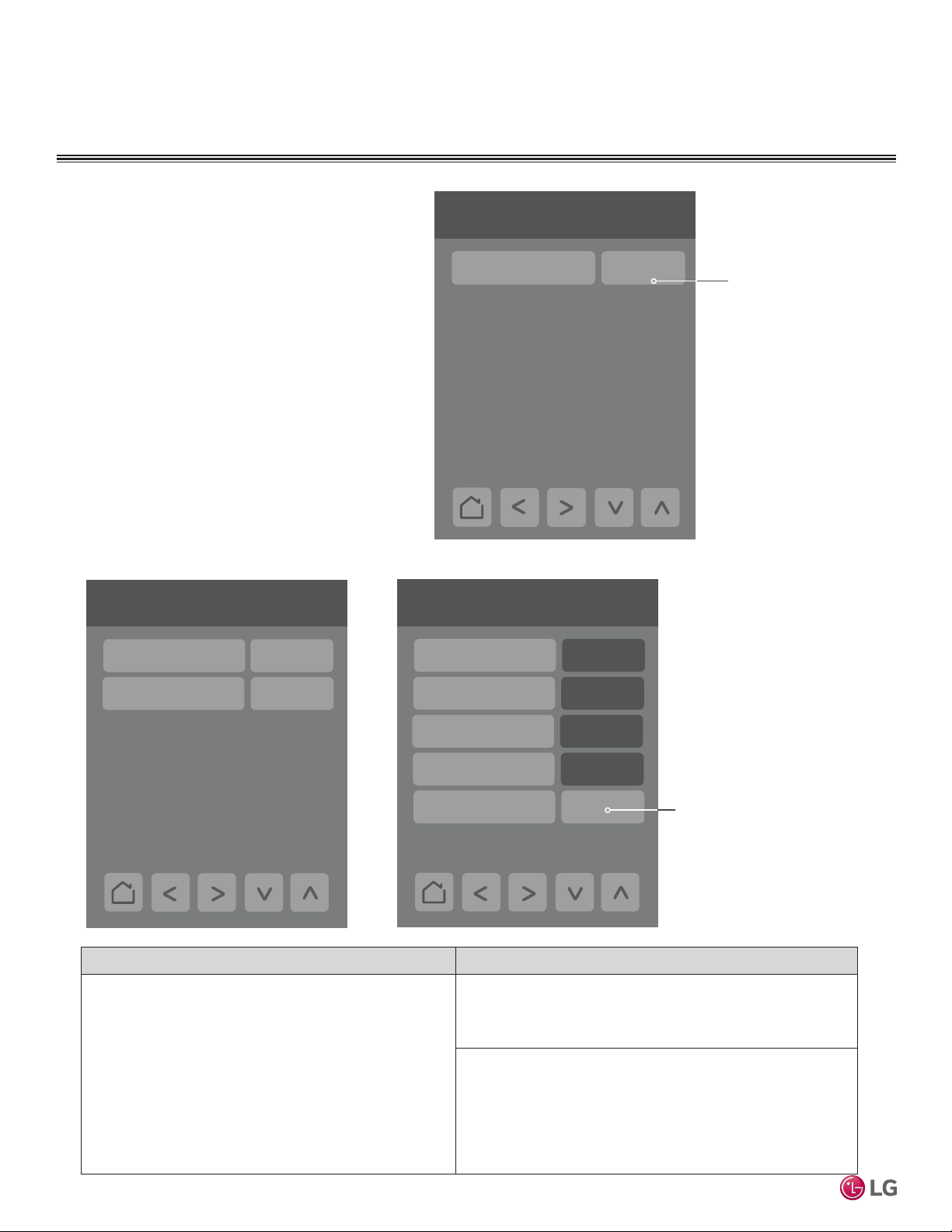
Setpoints Configuration
Press the Setpoint Cong button on the Building
Manager Screen to display the Setpoints Conguration
screen. Press the Single/Dual button to select single or
dual setpoint operation.
Note: If changes are made to Deadband and Setpoint
Min/Max values after scheduled events have already
been added to the Schedule Event table, the new rules
will be enforced only when the user enters back into the
Schedule Editor.
Setpoint Single / Dual 1/2
Single / Dual Dual SP(1)
Press up or down arrow
keys below to select
between Single our Dual
set point modes.
Note: Available functions/
features may differ based
on the connected system.
Single Setpoint Mode
Setpoint Single / Dual 2/2
Setpoint Max.
Setpoint Min.
86.0 °F
60.0 °F
MultiSITE CRC 1 Controller
Conguration Parameters Default Value Parameter Settings
Single/Dual
Default value: Dual SP(1)
Default value can be changed by user
Dual Setpoint Mode
Setpoints Config. 2/2
Cooling SP Max
Cooling SP Min
Heating SP Max
Heating SP Min
Deadband
Single SP
(Single Setpoint Adjustment)
Setpoint Maximum is 86 °F
Setpoint Minimum is 60 °F
Dual SP
(Dual Setpoints Adjustment)
Maximum upper cooling temperature is 99 °F
Minimum lower cooling temperature is 52 °F
Maximum upper heating temperature is 90 °F
Minimum lower heating temperature is 40°F
Deadband range is 1 °F - 10 °F
99 °F
52 °F
90 °F
40 °F
4 °F
Minimum deadband value
between the heating and cooling
setpoints. Applied only when any
of the setpoints are modied.
Range is 1 °F - 10 °F
24
Due to our policy of continuous product innovation, some specifications may change without notification.
©LG Electronics U.S.A., Inc., Englewood Cliffs, NJ. All rights reserved. “LG” is a registered trademark of LG Corp.
Page 25
CONFIGURATION SCREENS
74°F
70°F
Override
Setpoint cool
Setpoint heat
Auto
System mode
Fan speed
Override (min.)
Med
30
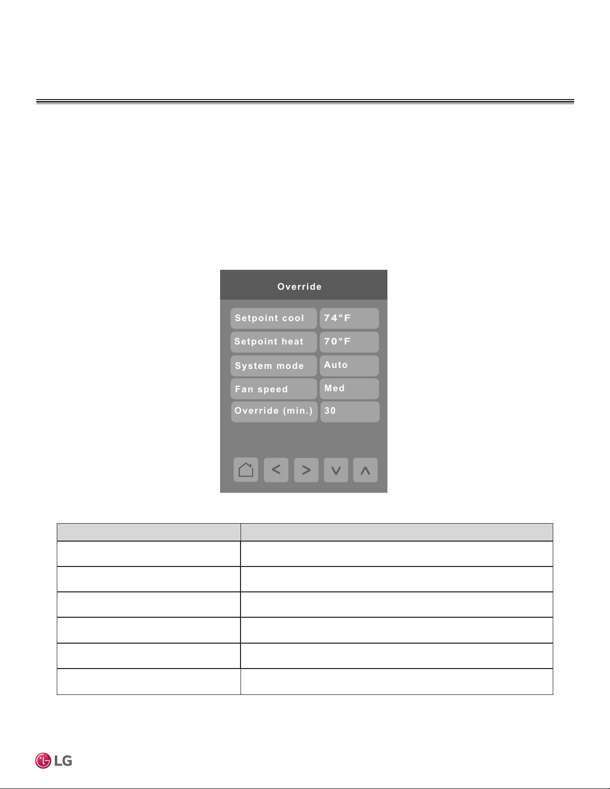
Override Setup
Press the Override Setup button on the Building Manager screen to display the Override Setup screen. The user can configure override settings including set points, system mode, fan speed and override duration.
Override Operation
Override mode can only be activated if the current system status is Unoccupied. If this condition is met, the controller will
enter Override mode as soon as the user taps the screen the first time (from dim state). If the user makes any changes to
the settings, those are accepted and the controller stays in Override mode. When the override timer expires, the controller
returns to the original settings (Mode, Fan Speed, Set Points) in effect prior to entering Override. If a scheduled event starts
during Override mode, the controller accepts the scheduled event and exits Override mode.
User Interface Guide
Setpoint (Single Setpoint)
Default value: 72°F
Setpoint cool (Dual Setpoint)
Default value: 78°F
Setpoint heat (Dual Setpoint)
Default value: 68°F
System mode
Default value: Auto
Fan Speed
Default value: Medium
Override
Default value = 30 minutes
Default Parameters are dependent on if the controller is in Single Setpoint Mode or Dual Setpoint Mode.
Conguration Parameters Default Value Parameter Settings
Range: Heating Mode: 60-86 °F
Cooling Mode: 64-86 °F
Range: 52-99 °F
Range: 40-90 °F
Choices: Slow, Low, Low-Med, Medium, Med-High, High, Power, Auto
Choices: Low, Medium, High, Auto
Temporary occupancy override for controller
Adjustable: 30 to 240 minutes
Due to our policy of continuous product innovation, some specifications may change without notification.
©LG Electronics U.S.A., Inc., Englewood Cliffs, NJ. All rights reserved. “LG” is a registered trademark of LG Corp.
25
Page 26
CONFIGURATION SCREENS
Setback
Setpoint cool
Setpoint heat
System mode
Fan speed
74°F
70°F
Med
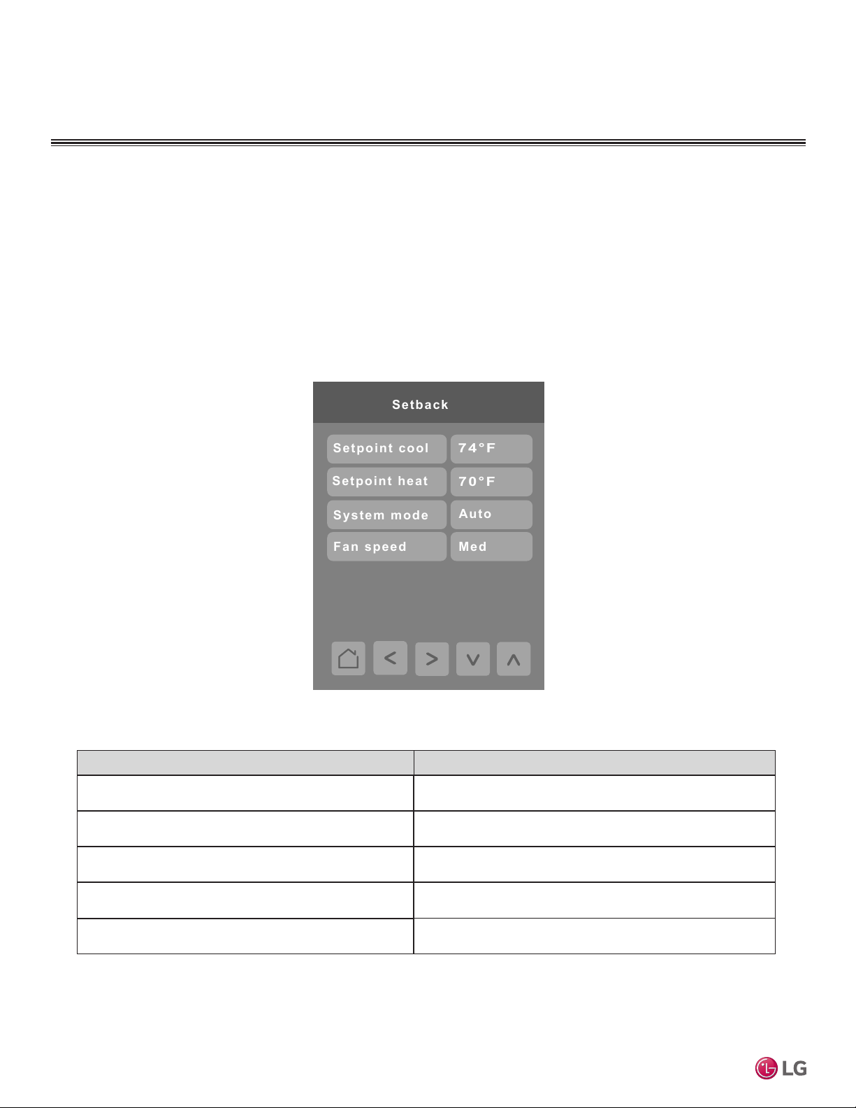
Setback Setup
Press the Setback Setup button on the Building Manager screen to display the Setback Setup screen. Setback parameters
including set points, system mode, and fan speed are configured on this screen.
Setback Operation
If the controller is in Setback mode and the user changes the Mode, Fan Speed or Set Points, the controller exits Setback
mode and keeps settings as applied by the user until the next scheduled event occurs. Setback mode can also be exited if
the user presses the Setback mode button again from the Operation Mode screen while in Setback mode. The setback icon
on the Operation Mode screen will indicate if that mode is active or not.
MultiSITE CRC 1 Controller
Conguration Parameters Default Value Parameter Settings
Setpoint (Single Setpoint)
Default value: 72°F
Setpoint cool (Dual Setpoint)
Default value: 78°F
Setpoint heat (Dual Setpoint)
Default value: 68°F
System mode
Default value: Auto
Fan Speed
Default value: Medium
Default Parameters are dependent on if the controller is in Single Setpoint Mode or Dual Setpoint Mode.
26
Range: Heating Mode: 60-86 °F
Cooling Mode: 64-86 °F
Range: 52-99 °F
Range: 40-90 °F
Choices: Auto, Dry, Off, Cool, Heat, Fan
Choices: Slow, Low, Low-Med, Medium, Med-High, High,
Power, Auto
Due to our policy of continuous product innovation, some specifications may change without notification.
©LG Electronics U.S.A., Inc., Englewood Cliffs, NJ. All rights reserved. “LG” is a registered trademark of LG Corp.
Page 27
CONFIGURATION SCREENS
Outdoor Unit Control
Defrost/Snow(49)
Snow Rmvl(1)
Smart load contrl
Eco. Cool(44)
Silent Mode Start
Normal(2)
Disable(0)
Silent Mode End
--:--
--:--
ODU(0)
Silent Mode Cntrl Loc
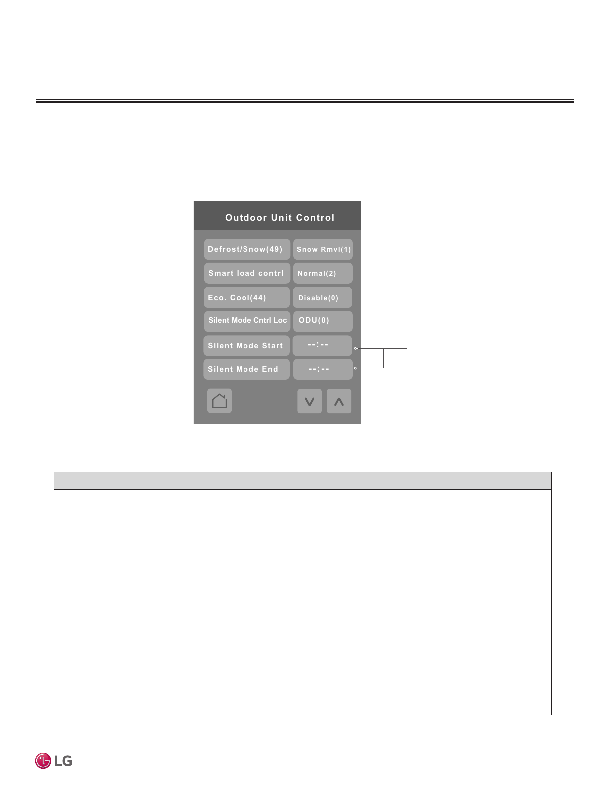
Outdoor Unit Control
Press the Outdoor Unit Control button on the Building Manager screen to display the Outdoor Unit Control screen. The Outdoor Unit Control lets you manage outdoor units through the controller interface.
User Interface Guide
Conguration Parameters Default Value Parameter Settings
Defrost/Snow(49)
Default value = Disable(0)
Smart load contrl
Default value = Disable(0)
Eco. Cool(44)
Default value = Disable(0)
Silent Mode Cntrl Loc
Default value = ODU(0)
Silent Mode Start/End
Default value = “--:--”
Set start time and end time
for Silent Mode
0 = “Disable (0)”
1 = “Snow Rmvl (1)”
2 = “Fast Dfrst (2)”
3 = “Both (3)”
0 = “Disable (0)”
1 = “Efcient (1)”
2 = “Normal (2)”
3 = “Power (3)”
0 = “Disable (0)”
1 = “Low-Savings (1)”
2 = “Mid-Savings (2)”
3 = “Hi-Savings (3)”
Choices: ODU(0) Remote(1)
Time of day in either AM/PM or 24 hr. format (depending on
control setting in Display / Date & Time section)
Due to our policy of continuous product innovation, some specifications may change without notification.
©LG Electronics U.S.A., Inc., Englewood Cliffs, NJ. All rights reserved. “LG” is a registered trademark of LG Corp.
27
Page 28
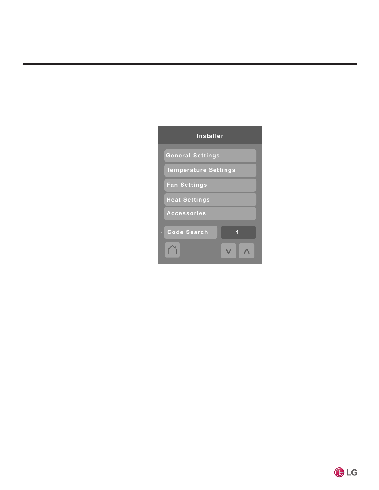
CONFIGURATION SCREENS
Fan Settings
Installer
General Settings
Temperature Settings
Heat Settings
Accessories
1
Code Search
Installer
Press the Installer button on the Configuration screen to display the Installer screen. The Installer menu lists
the controller’s setup parameters and the accessories menu.
Code Search
Use the Up and Down arrows
to choose an available Function
Code and select the Code Search
button to navigate to the screen
where that function code resides.
Codes can be found in brackets
next to a parameter throughout all
MultiSITE CRC 1 Controller
menus. This function is used for
quicker menu navigation.
28
Due to our policy of continuous product innovation, some specifications may change without notification.
©LG Electronics U.S.A., Inc., Englewood Cliffs, NJ. All rights reserved. “LG” is a registered trademark of LG Corp.
Page 29
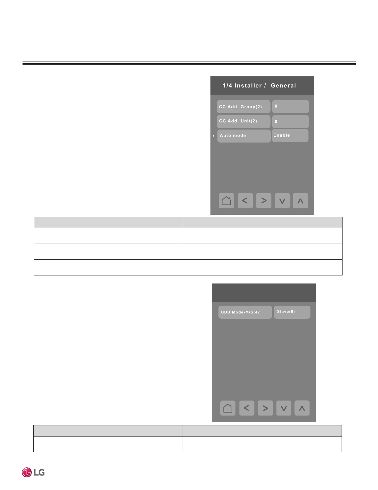
General Settings
0
Enable
0
CC A dd. Group(2)
Auto mode
1/ 4 Installer / G eneral
CC A dd. Unit(2)
Slave(0)
ODU Mode-M/S(47)
There are four Installer / General Settings screens. Press General
Settings on the Installer screen to display the first General Settings
screen. Press the right arrow on the screen to display screens 2, 3,
and 4.
This value will be used to
decide if Auto mode appears
in the Operation Mode screen
and whether to show “Auto”
text at the top of the Home
screen during Auto operation
mode.
CONFIGURATION SCREENS
User Interface Guide
Conguration Parameters Default Value Parameter Settings
Central Controller Add. Group(2)
Default value = 0
Central Controller Add. Unit(2)
Default value = 0
Auto mode
Default value = Disable
Choices: 0 - F
Choices: 0 - F
Choices: Enable, Disable
2/ 4 Installer / G eneral
ODU Mode - M/S (47)
Default value = Slave (0)
Conguration Parameters Default Value Parameter Settings
0 = “Slave (0)”
1 = “Master (1)”
Due to our policy of continuous product innovation, some specifications may change without notification.
©LG Electronics U.S.A., Inc., Englewood Cliffs, NJ. All rights reserved. “LG” is a registered trademark of LG Corp.
29
Page 30
CONFIGURATION SCREENS
Master(1)
30 M in(2)
Cooling(1)
Test run(1)
Guard T imer(33)
IDU A uto Start(39)
Enable(1)
IDU Mode- M/S(8)
Gr p C ntrl Funcs(19)
Di sable(0)
Mode 1(1)
Ref. Noise Red. (48)
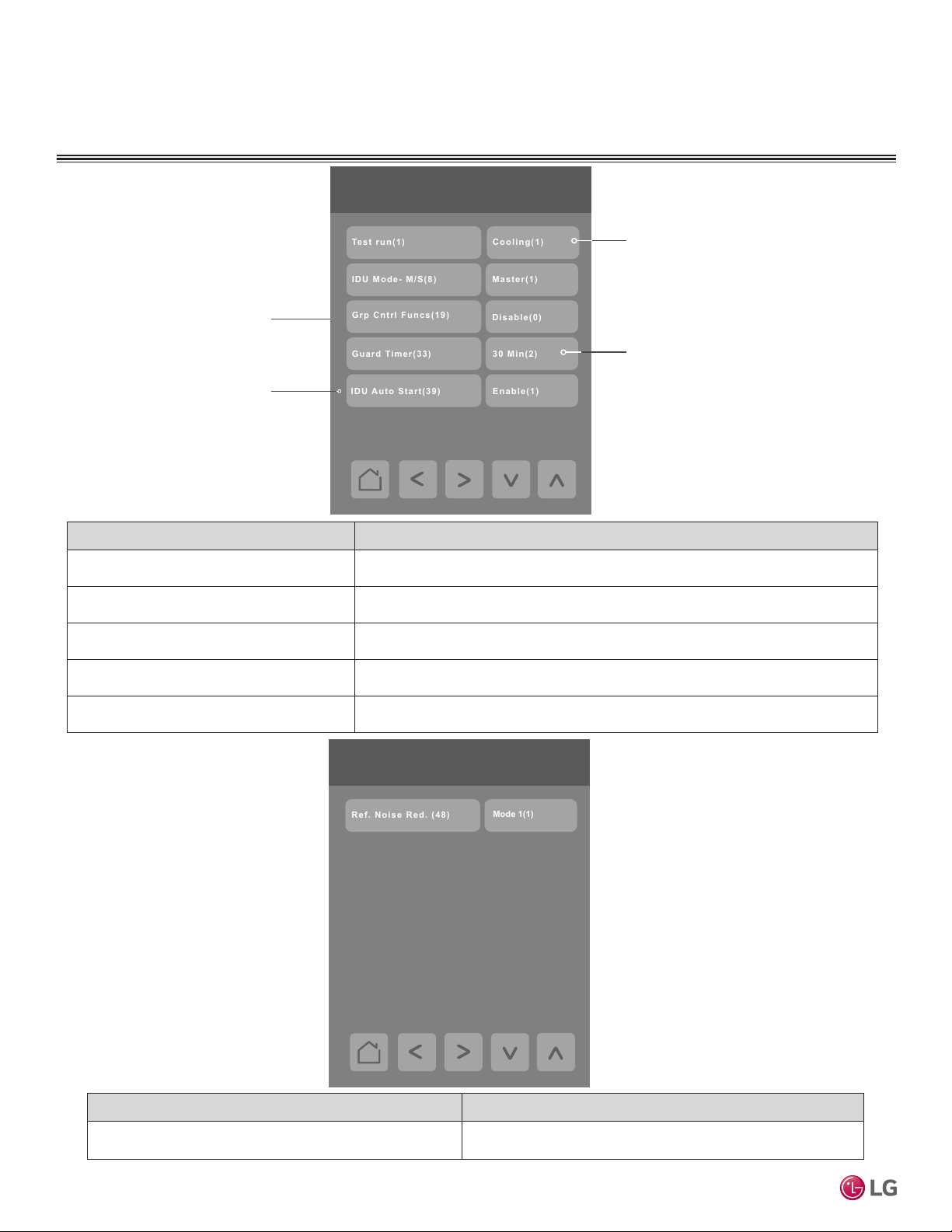
Use this function to enable or
disable Group Control for the
system.
Use this function to enable or
disable Indoor Unit Auto Start.
Conguration Parameters Default Value Parameter Settings
Test run(1)
Default value = Off
IDU Mode - M/S(8)
Default value = Slave(0)
Grp Cntrl Funcs(19)
Default value = Disable(0)
Guard Timer(33)
Default value = 15 min(1)
IDU Auto Start(39)
Default value = Enable(1)
MultiSITE CRC 1 Controller
3/ 4 Installer / G eneral
Using the Up and Down arrows select
between Heating, Cooling or Off
modes. The Test run will end after 18
minutes and then turn system off. Test
mode can be interrupted by changing
fan speed, set point, or turning off the
IDU from the home screen.
Using the Up and Down arrows select
a guard time of 0, 15, 30, 45 or 60
minutes.
Choices: Off(0), Cooling(1), Heating(2)
Choices: Slave(0), Master(1)
Choices: Disable(0), Enable(1)
Choices in minutes: 0 min(0), 15 min(1), 30 min(2), 45 min(3), 60 min(4)
Choices: Enable(0), Disable(1)
4/ 4 Installer / G eneral
30
Conguration Parameters Default Value Parameter Settings
Refrig Noise Red. (48)
Default value = Disable(0)
Choices:
0 = "Disable(0)" 1 = "Mode1(1)" 2 = "Mode 2(2)
Due to our policy of continuous product innovation, some specifications may change without notification.
©LG Electronics U.S.A., Inc., Englewood Cliffs, NJ. All rights reserved. “LG” is a registered trademark of LG Corp.
Page 31
CONFIGURATION SCREENS
RC(1)
1/ 2 Temp eratu re Settings
Temp Se ns Loc(4)
4°F(2)
Single S P Deadba n d
1°F(1)
Set Point Prec. (17)
4°F/7°F (2)
2/2 Temperature Settings
Heat. Therm(15)
2°F/-2°F (3)
Cool. Therm(27)
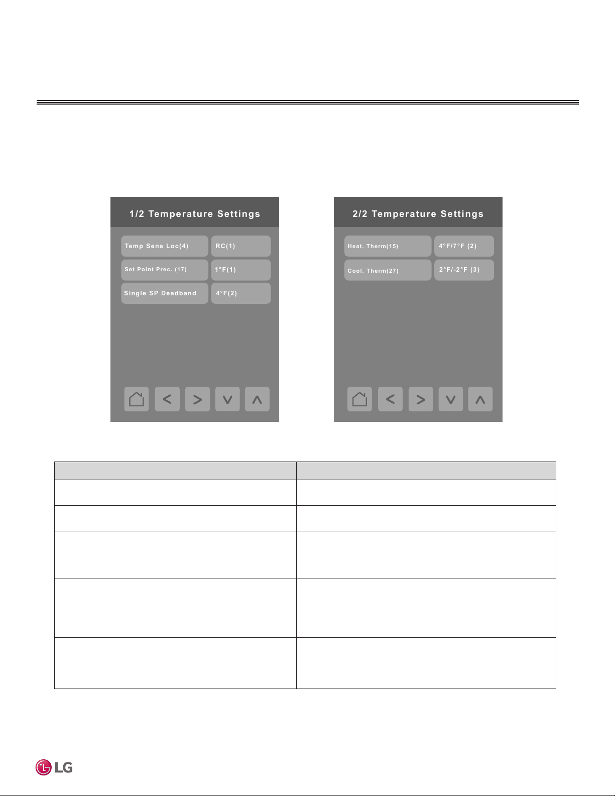
Temperature Settings
Press the Temperature Settings button on the Installer screen to display the Temperature Settings screen. Press the right
arrow button to display the second page of the Temperature Settings screen.
User Interface Guide
Conguration Parameters Default Value Parameter Settings
Temp Sens Loc (4)
Default value = 2TH(3)
Setpoint °C Prec. (17)
Default value = 0.5°C(1)
Single SP Deadband
Default value = Dual SP (when supported)
Heat Therm(15)
Default value = Default(0)
Cool Therm(27)
Default value = Default(0)
1 = “RC” (1)”, 2 = “IDU (2)”, 3 = “2TH (3)”
1°C(0), 0.5°C(1)
1 = “2°F (1)” 5 = “9°F (5)”
2 = “4°F (2)” 6 = “11°F (6)”
3 = “5°F (3)” 7 = “13°F (7)”
4 = “7°F (4)”
0 = “Default (0)”
1 = “7°F/11°F (1)”
2 = “4°F/7°F (2)”
3 = “-2°F/2°F (3)”
4 = “-1°F/1°F (4)”
0 = “Default (0)”
1 = “11°F/7°F (1)”
2 = “7°F/4°F (2)”
3 = “2°F/-2°F (3)”
Due to our policy of continuous product innovation, some specifications may change without notification.
©LG Electronics U.S.A., Inc., Englewood Cliffs, NJ. All rights reserved. “LG” is a registered trademark of LG Corp.
31
Page 32
CONFIGURATION SCREENS
Fan Low(0)
1/2 Fan Settings
Fxd Fan Speed(11)
Cool Therm Off(35)
Fan/Vnt inter(38)
11.9-13.8’(4)
Ceiling height(5)
Fixed H(2)
Static pressure(6)
Fan Off(0)
Fan Off(0)
Use SP(0)
2/2 Fan Settings
Sta Pres Step(32)
Enable(1)
Fan Auto Therm Off
IDU Auto Dry
Disable(0)
Delay Fan Off(46)
Speed By Temp(51)
Disable(0)
Enable(1)
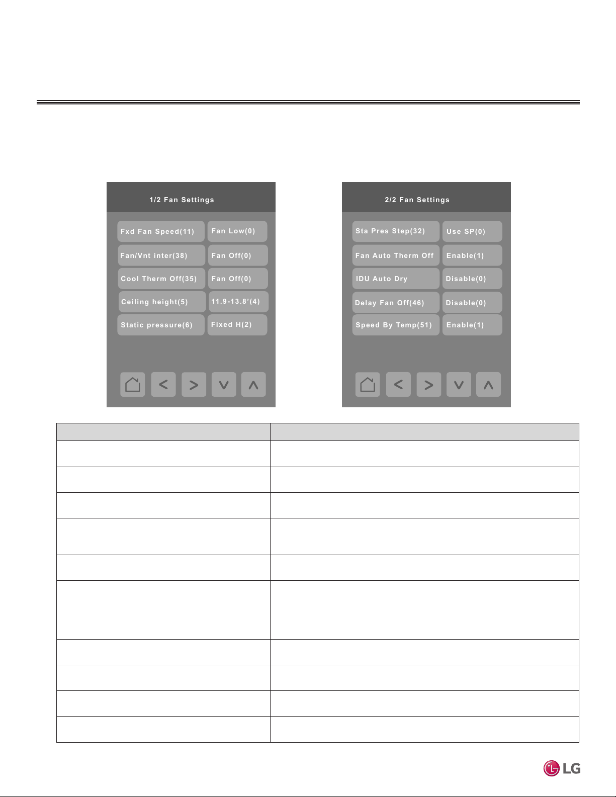
Fan Settings
Press the Fan Settings button on the Installer screen to display the Fan Settings screen. Press the right arrow
button to display the second page of the Fan Settings screen.
Conguration Parameters Default Value Parameter Settings
Fxd Fan Speed(11)
Default value = IDU Cntrl(0)
MultiSITE CRC 1 Controller
Fan/Vnt inter(38)
Default value = Fan Off(0)
Cool Therm Off(35)
Default value = Low(0)
Ceiling height(5)
Default value = 8.8-10.6'(2)
Static pressure(6)
Default value = Fixed H(2)
Sta Pres Step(32)
Default value = Use SP(0)
Fan Auto Therm Off
Default value = Disable(0)
IDU Auto Dr y
Default value = Disable(0)
Delay Fan Off(46)
Default value = Disable(0)
Speed By Temp(51)
Default value = Disable(0)
Choices: IDU Cntrl (0), No Chng (1)
Choices: Fan Off (0), Fan Slow (1)
Choices: Fan Low (0), Fan Off (1), No Chng (2)
Choices:
1= "< 8.8' (1) - Low”
2 = “8.8-10.6' (2) - Stndrd”
3 = “10.5 – 11.8' -High (3)”
4 = “11.9-13.8' - Very High (4)
5= > 13.8' - Extremely High (5)
Choices: 1 = “Var. H (1)”, 2 = “Fixed H (2)”, 3 = “Var. L (3)”, 4 = “Fixed L (4)”
Choices:
0 = “Use SP (0)”
1 = “SPS 1 (1)”
2 = “SPS 2 (2)”
3 = “SPS 3 (3)”
4 = “SPS 4 (4)”
5 = “SPS 5 (5)”
6 = “SPS 6 (6)”
7 = “SPS 7 (7)”
8 = “SPS 8 (8)”
9 = “SPS 9 (9)”
10 = “SPS 10 (10)”
11 = “SPS 11 (11)”
Choices: 0 = “Disable (0)”, 1 = “Enable (1)”
Choices: 0 = “Disable (0)”, 1 = “Enable (1)”
Choices: 0 = “Disable (0)”, 1 = “Enable (1)”
Choices: 0 = “Disable (0)”, 1 = “Enable (1)”
32
Due to our policy of continuous product innovation, some specifications may change without notification.
©LG Electronics U.S.A., Inc., Englewood Cliffs, NJ. All rights reserved. “LG” is a registered trademark of LG Corp.
Page 33
CONFIGURATION SCREENS
Disable(0)
Heat Settings
Ext Aux Heat(25)
Aux Heat Ctrl(21)
HP First(0)
Prim Heat Ctrl(36)
Emergency Heater(18)
Disable(0)
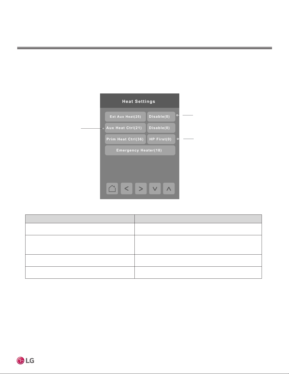
Heat Settings
Press the Heat Settings button on the Installer screen to display the Heat Settings screen.
Use this function to enable or
disable auxiliary heat control.
Using the Up and Down arrows select
between Disable, Non-Ducted and
Ducted.
Select between Primary Heat First and
Primary Heat Last.
User Interface Guide
Conguration Parameters Default Value Parameter Settings
Ext Aux Heat (25)
Default value = Disabled(0)
Aux Heat Cntrl(21)
Default value = Disabled(0)
Primary Heat Cntrl(36)
Default value = HP First(0)
Emergency Heater(18)
Default value = Disabled(0)
Choices: 0 = ‘Disable (0)”, 1 = “Non-Duct (0)” , 2 = “Ducted (1)”
This control is used to enable related control on MODE screen
that actually turns the Aux Heat on or off
Choices: 0 = “Disable (0)” , 1 = “Enable (1)”
Choices: HP First (0), HP Last (1)
Use this function to enable or disable emergency heating.
Choices: 0 = “Disable (0)” , 1 = “Enable (1)”
Due to our policy of continuous product innovation, some specifications may change without notification.
©LG Electronics U.S.A., Inc., Englewood Cliffs, NJ. All rights reserved. “LG” is a registered trademark of LG Corp.
33
Page 34
CONFIGURATION SCREENS
Enable(1)
Emerg e n cy Heater(18)
Mode
Heater
Off/On
Fan
-10°F/-5°F(1)
Va lue 3
Va lue 2
Va lue 1
Outside Air
On T emp/Off T emp
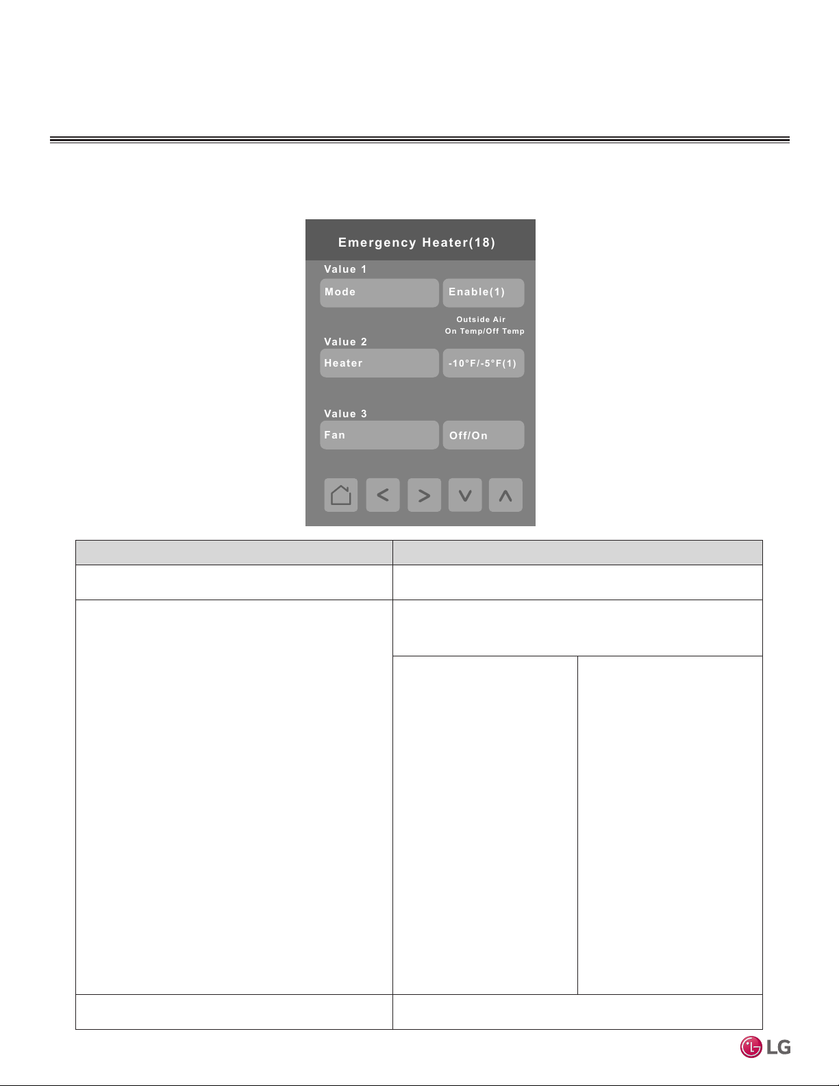
Emergency Heater Settings
Press the Emergency Heater button on the Heat Settings screen to display the Emergency Heater Settings screen.
Conguration Parameters Default Value Parameter Settings
Value 1 (Mode)
Default value = Disabled(0)
Value 2 (Outside Air On/Off Temp)
Default value = Disabled(0)
MultiSITE CRC 1 Controller
Value 3 (Fan)
Default value = Off(0)
Choices: Disable (0), Enable (1)
Choices: Column 1 or Column 2
Only Column 1 is available on Gen. 2 equipment.
Column 2 values are available on Gen. 4 and newer equipment.
Column 1
1– “-10°F / -4°F (1)”
2 – “-6°F / 0°F (2)”
3 – “0°F / 4°F (3)”
Column 2
1– “-10°F / -4°F (1)”
2 – “-6°F / 0°F (2)”
3 – “0°F / 4°F (3)”
4 – “4°F / 10°F (4)”
5 – “10°F / 16°F (5)”
6 – “16°F / 20°F (6)”
7 – “20°F / 24°F (7)”
8 – “24°F / 30°F (8)”
9 – “30°F / 36°F (9)”
10 – “36°F / 40°F (10)”
11 – “40°F / 44°F (11)”
12 – “44°F / 50°F (12)”
13 – “50°F / 56°F (13)”
14 – “56°F / 60°F (14)”
15 – “60°F / 64°F (15)”
Off (0), On (1)
34
Due to our policy of continuous product innovation, some specifications may change without notification.
©LG Electronics U.S.A., Inc., Englewood Cliffs, NJ. All rights reserved. “LG” is a registered trademark of LG Corp.
Page 35
CONFIGURATION SCREENS
Auto Off(0)
Disable(0)
1/2 Accessories
Dry Cont Enbl(41)
Dry cont. Auto(9)
CN_EXT Cnfg(52)
Out. Air-Vent(24)
EmrgAlrm(5)
Enable(1)
Plasma Kit(20)
Enable(1)
Grill Elev Kit(23)
Disable(0)
Disable(0)
2/2 Accessories
Refrig Leak Sns(29)
Disable(0)
Cntrlr Occ Sensor
30 min
Cntrlr Min Occ On
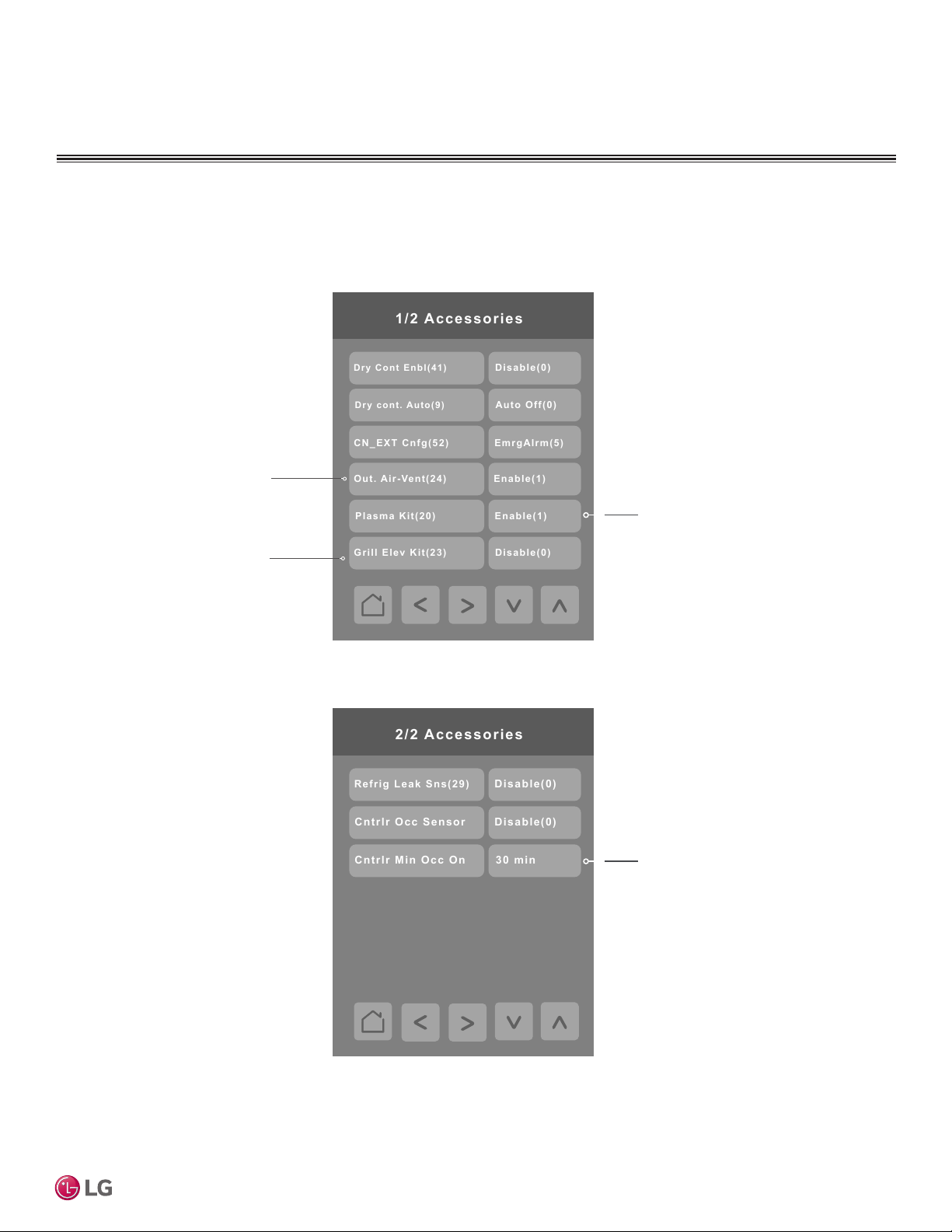
Accessories
Press the Accessories button on the Installer screen to display the Accessories screen. Press the right arrow to display the
second page of the Accessories screen.
This option enables the related
control on the MORE screen that
turns the Vent kit on or off.
This option enables the related
control on the Filter Functions
screen that controls Raise/Lower
Grill functions.
This option enables the related control
on the MORE screen that turns the
Plasma Purifier on or off.
User Interface Guide
Global setting which applies to both
the onboard PIR sensor as well as any
installed ZigBee motion sensors.
Due to our policy of continuous product innovation, some specifications may change without notification.
©LG Electronics U.S.A., Inc., Englewood Cliffs, NJ. All rights reserved. “LG” is a registered trademark of LG Corp.
35
Page 36
CONFIGURATION SCREENS
Accessories – continued
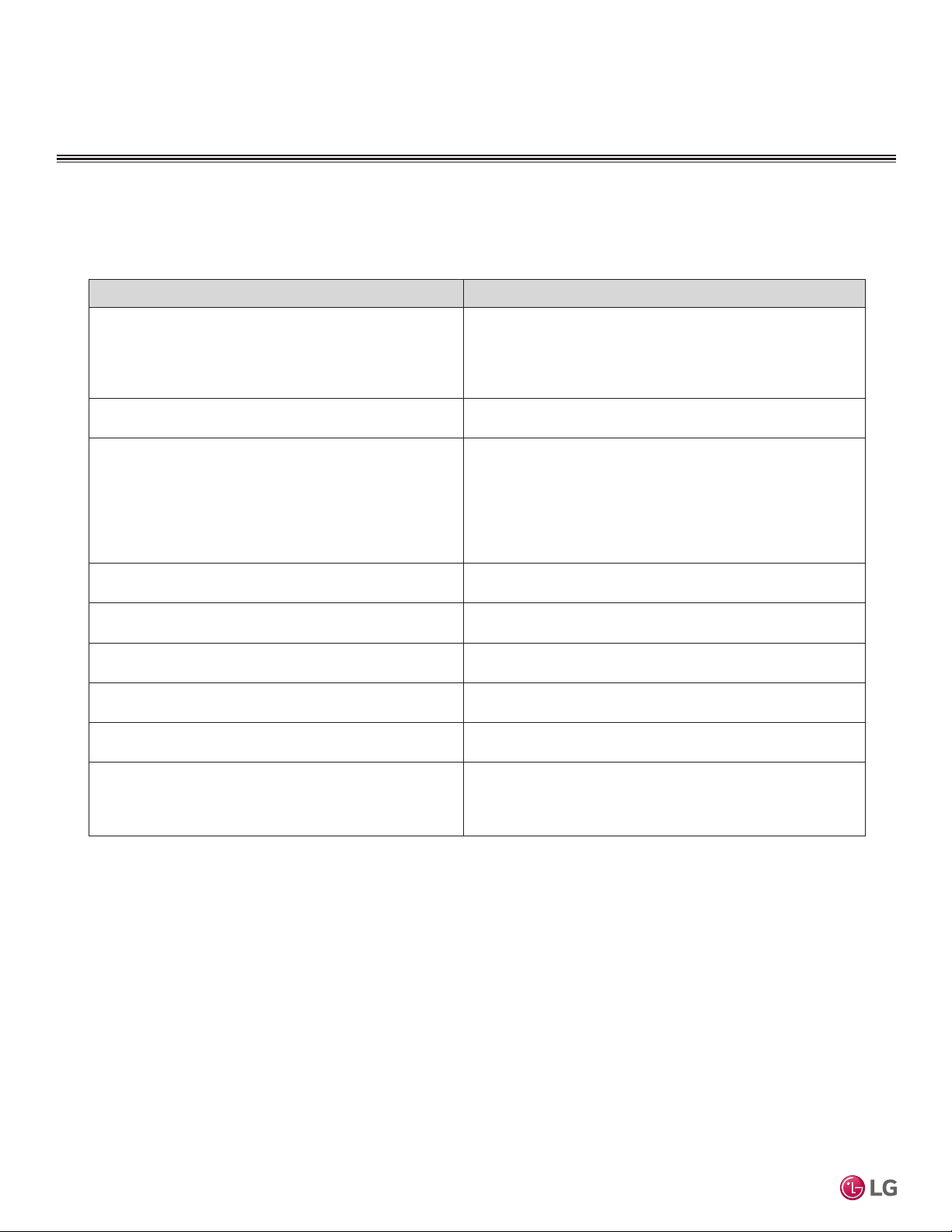
Conguration Parameters Default Value Parameter Settings
Dry Cont Enbl(41)
Default value = Disabled(0)
Dry cont. Auto(9)
Default value = Disabled(0)
CN_EXT Cnfg (52)
Default value = Disabled(0)
Out. Air – Vent (24)
Default value = Disabled(0)
Plasma Kit (20)
Default value = Disabled(0)
Grill Elev. Kit (23)
Default value = Disabled(0)
Refrig Leak Sns(29)
Default value = Disabled(0)
MultiSITE CRC 1 Controller
Cntrlr Occ Sensor
Default value = Disabled(0)
Cntrlr Min Occ On
Default value = 10 min (0)
Choices:
0 = “Disable (0)”
1 = “Not Used (1)”
2 = “Enabled (2)”
3 = “Use CN_EXT (3)”
Choices: 0 = “Auto Off (0)”, 1 = “Auto On (1)”
Choices:
0 = “Disable (0)”
1 = “On/Off (1)”
2 = “DryCntct (2)”
3 = “Stp1IDU (3)”
4 = Reserved
5 = “StpIDUs (5)”
Choices: 0 = “Disable (0)”, 1 = “Enable (1)”
Choices: 0 = “Disable (0)”, 1 = “Enable (1)”
Choices: 0 = “Disable (0)”, 1 = “Enable (1)”
Choices: 0 = “Disable (0)” , 1 = “Enable (1)”
Choices: 0 = “Disable”, 1 = “Enable”
Choices:
0 = “10 min (0)”
1 = “30 min (1)”
2 = “60 min (2)”
36
Due to our policy of continuous product innovation, some specifications may change without notification.
©LG Electronics U.S.A., Inc., Englewood Cliffs, NJ. All rights reserved. “LG” is a registered trademark of LG Corp.
Page 37
CONFIGURATION SCREENS
BMS Config
BACnet settings
ZigBee Config
Imperial
254
BACnet Network 1 /2
CO M address
Network units
Au t o
Baud rate
Offline
BACnet statu s
BMS Configuration
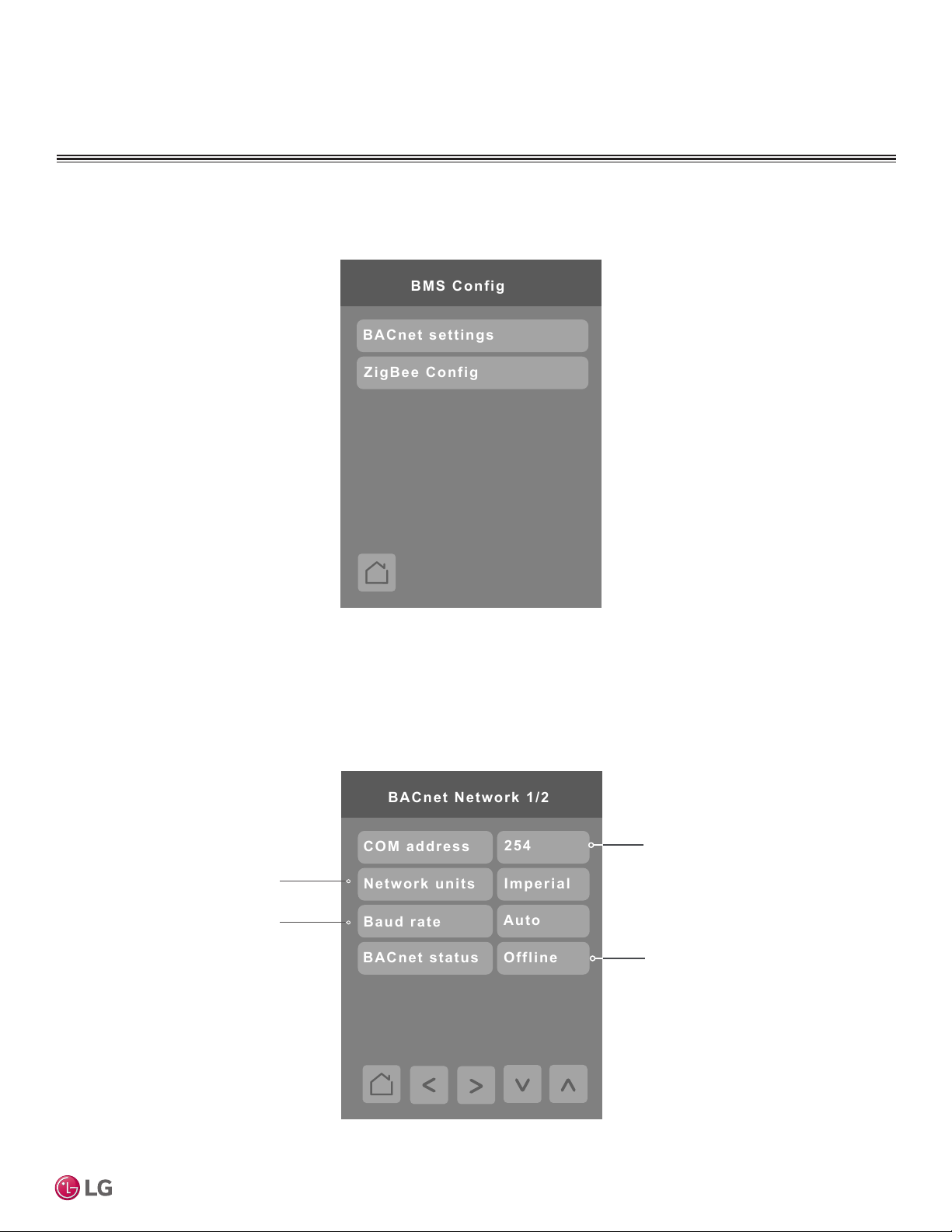
Press the BMS Config button on the Configuration screen to display the BMS Config screen.
User Interface Guide
BACnet Settings
Press the BACnet* settings button on the BMS Config screen to display the BACnet Network screen. Press the right arrow to
display the BACnet Instance screen.
"254" value will set BACnet
network "Offline." To activate
Imperial or Metric units
Baud rate settings
"Online," choose a different
value
Indicates the controller
status on the network.
*BACnet is a registered trademark of ASHRAE
Due to our policy of continuous product innovation, some specifications may change without notification.
©LG Electronics U.S.A., Inc., Englewood Cliffs, NJ. All rights reserved. “LG” is a registered trademark of LG Corp.
37
Page 38
CONFIGURATION SCREENS
0830057
BACnet Instance
BACnet Settings – continued
Conguration Parameters Default Value Parameter Settings
COM address
Terminal Equipment Controller
Networking address
Default value = 254
Range is: 0 to 254
Network units
Default value = SI
Baud rate
Default value = Auto
Communications Address
For BACnet MS/TP models, the valid range is from 0 to 253.
Default value of 254 disables BACnet communication for the
Controller.
Measurement Units
Imperial: Network units shown as “imperial” units.
SI: Network units shown as “international metric” units.
Baud Rate
Auto: Will automatically detect the BACnet MS/TP baud rate.
Other choices: (115200) (76800) (57600) (38400) (19200)
(9600)
Leave the value at auto unless instructed otherwise.
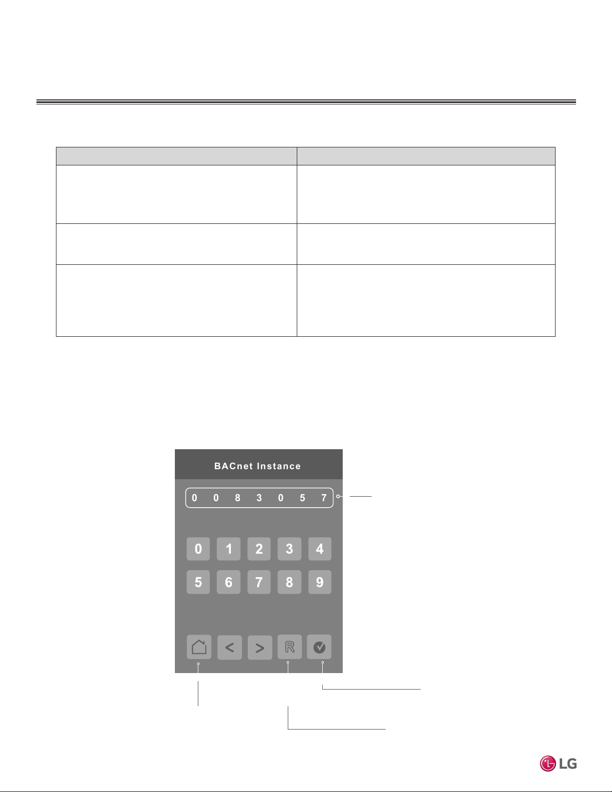
The default BACnet instance number is generated by the model number and COM address of the controller. For
example, the instance number of a MultiSITE CRC1 Series with a COM address of 57 is generated as “83057”.
The default instance number appears first. To change the instance number, use number pad and press Accept
and save.
Press Reset to automatic instance addressing to reset to automatic instance addressing.
MultiSITE CRC 1 Controller
Instance number of the controller.
38
Back to Setup page
Reset to automatic instance
addressing
Due to our policy of continuous product innovation, some specifications may change without notification.
©LG Electronics U.S.A., Inc., Englewood Cliffs, NJ. All rights reserved. “LG” is a registered trademark of LG Corp.
Accept and save
Page 39
CONFIGURATION SCREENS
1/3 Zigbee Configuration
Zigbee channel
Zigbee PAN ID
COM address
15
11
254
Zigbee short
0x0000
Node type
Zigbee status
No NWK
Coord.
ZigBee Configuration
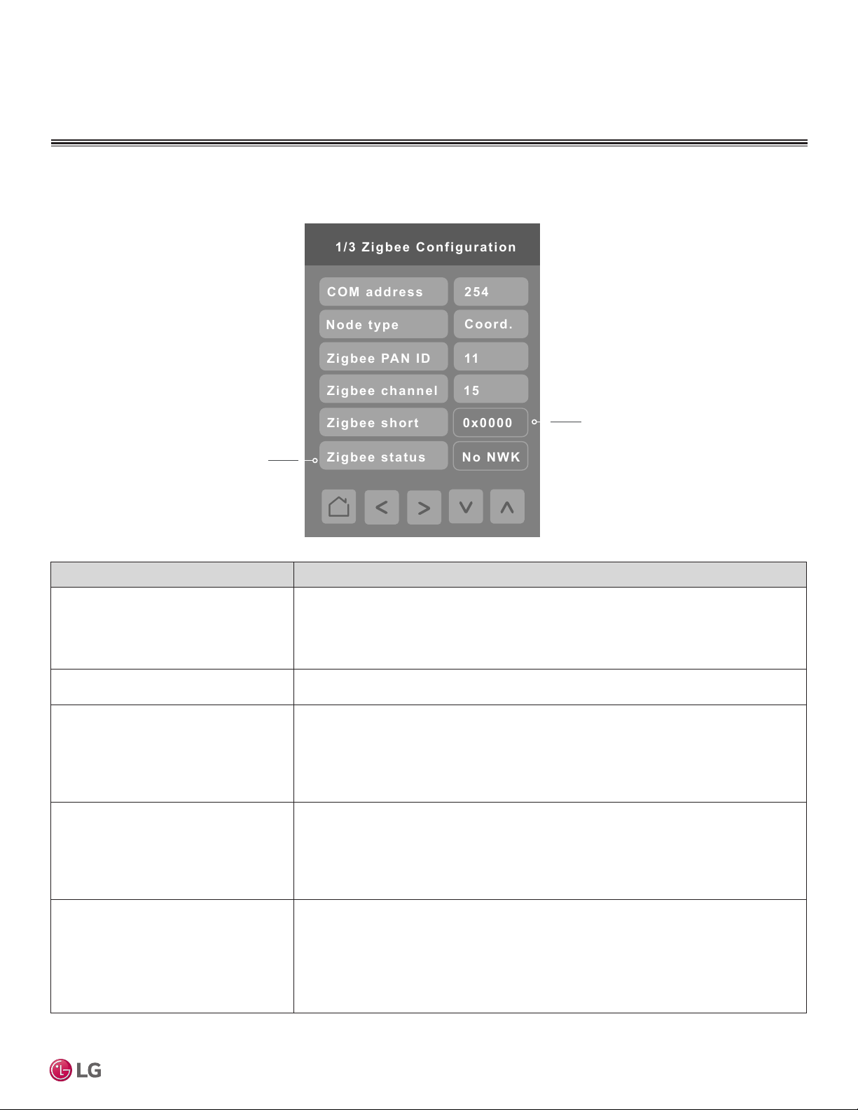
Press the ZigBee* Config button on the BMS Config screen to display the ZigBee Configuration screen.
ZigBee Pro short address. The address
Status of controller detecting a ZigBee
network. Will display Online when connected successfully to network.
is generated once the device joins a
ZigBee network.
User Interface Guide
Conguration Parameters Default Value Parameter Settings
COM address
Terminal Equipment
Controller networking address
Default value = 254
Range is: 0 to 254
Node type
Coord; Router
ZigBee Pan ID
Personal Area Network Identication
Default value = 0
Range is: 1 to 1000
ZigBee channel
Channel selection
Default value = 10
Range is: 10 to 25
ZigBee status
(read only)
For wireless models, the use of the COM address is not mandatory. COM address is
an optional way to identify a device on the network and is recommended if used with an
MPM.
It is Mandatory for BACnet.
Set Node type to Coord if controller will be responsible for controlling Zigbee sensor
network.
This parameter (PAN ID) links specic Controllers to specic ZigBee coordinators. For
every Controller reporting to a coordinator, make sure to set the SAME channel value
both on the coordinator and the Controllers.
The default value of 0 is NOT a valid PAN ID. The valid range of available PAN ID is from
1 to 1000.
This parameter (Channel) is used to link specic Controllers to specic ZigBee
coordinators. For every Controller reporting to a coordinator, be sure you set the SAME
channel value both on the coordinator and the Controller(s).
Using channels 15 and 25 is recommended.
The default value of 10 is NOT a valid channel. The valid range of available channels is
from 11 to 25.
ZigBee status
The following read only messages show in this eld:
• (Not Det): ZigBee Pro module not detected
• (Pwr On): ZigBee Pro module detected but not congured
• (No NWK): ZigBee Pro congured but no network joined
• (Joined): ZigBee Pro network joined
• (Online): Communicating
*ZigBee is a registered trademark of the ZigBee Alliance.
Due to our policy of continuous product innovation, some specifications may change without notification.
©LG Electronics U.S.A., Inc., Englewood Cliffs, NJ. All rights reserved. “LG” is a registered trademark of LG Corp.
39
Page 40
CONFIGURATION SCREENS
Door status
Closed
Door installed
Yes
Window status
Closed
Win. installed
Yes
Permit join
On
Low bat. alarm
On
2/3 Zigbee Configuration
ZigBee Configuration – continued
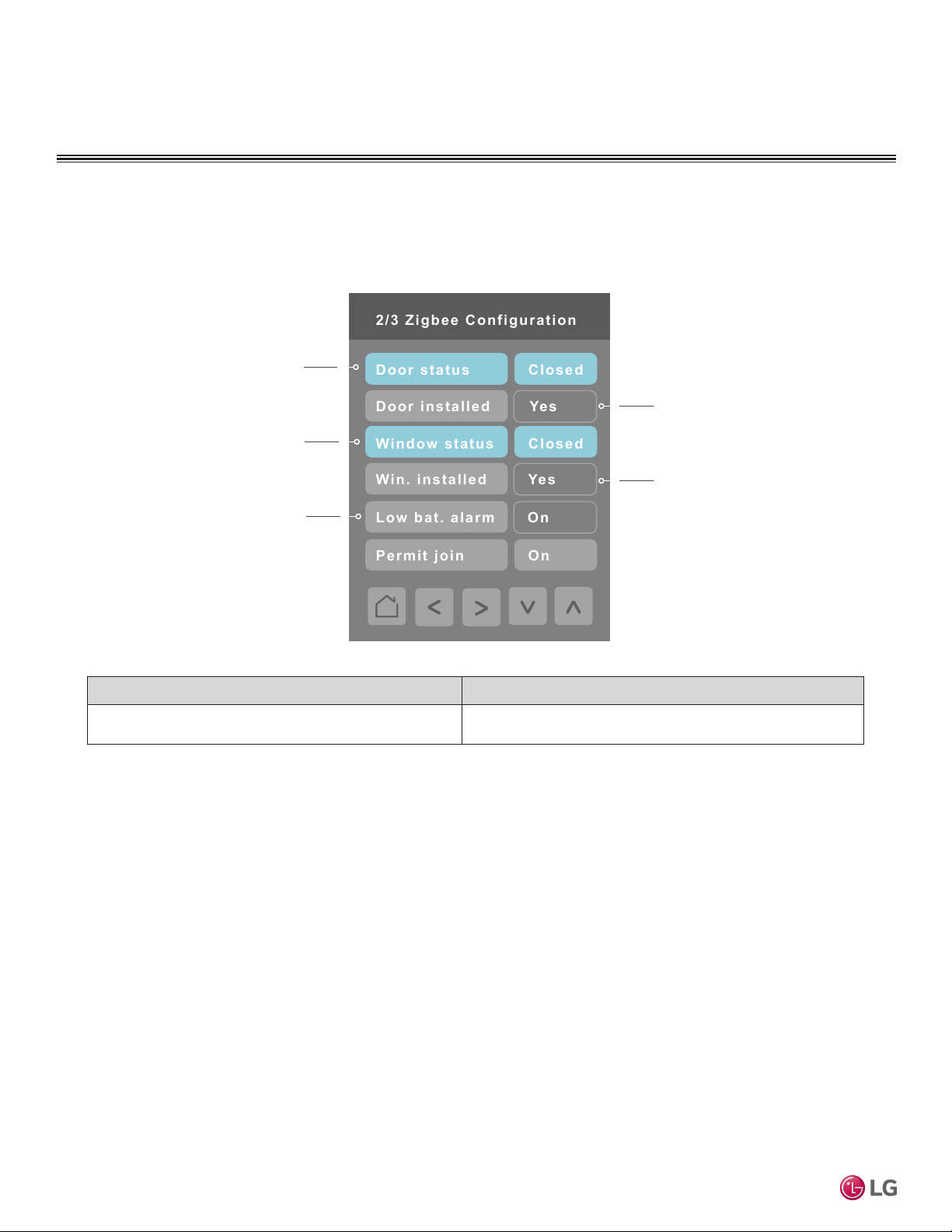
Press the right arrow on the ZigBee Configuration screen to display the second page of the ZigBee Configuration
screen. The blue fields indicate the controller is paired with a sensor.
Door contact
status if installed
Indicates if the door
Window contact
status if installed
Battery status
of wireless switch
contact is installed
Indicates if the window
contact is installed
Conguration Parameters Default Value Parameter Settings
Permit join
MultiSITE CRC 1 Controller
Default value = On
Changing this value to "Off" will lockout any new ZigBee
devices from joining the network through this controller.
40
Due to our policy of continuous product innovation, some specifications may change without notification.
©LG Electronics U.S.A., Inc., Englewood Cliffs, NJ. All rights reserved. “LG” is a registered trademark of LG Corp.
Page 41
CONFIGURATION SCREENS
ZigBee Configuration – continued
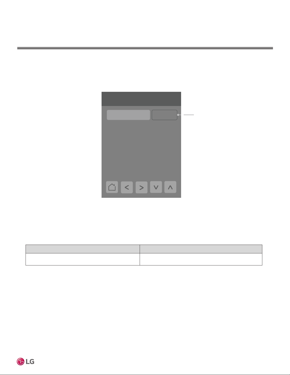
Press the right arrow on the ZigBee Configuration screen to display the third page of the ZigBee Configuration screen.
3/3 Zigbee configuration
Conguration Parameters Default Value Parameter Settings
IEEE address
Default value = 0x0000
IEEE address 0x0000
The extended IEEE ZigBee node address is used to identify
the device on the network.
Only last 4 digits in
HEX show
User Interface Guide
Due to our policy of continuous product innovation, some specifications may change without notification.
©LG Electronics U.S.A., Inc., Englewood Cliffs, NJ. All rights reserved. “LG” is a registered trademark of LG Corp.
41
Page 42
CONFIGURATION SCREENS
1.0.5-7a9a
1/ 6 Basic Dia gnosti c
Firmware rev.
Pipe temp conf.
ODU Status
On
On
78 °F
52 °F
2/ 6 Basic Dia gnosti c
Outlet pipe temp.
---
Middle pipe temp.
Middle point temp .
Off
ODU silent mode
Inlet pipe temp.
Off
Smart load contrl
Basic Diagnostic
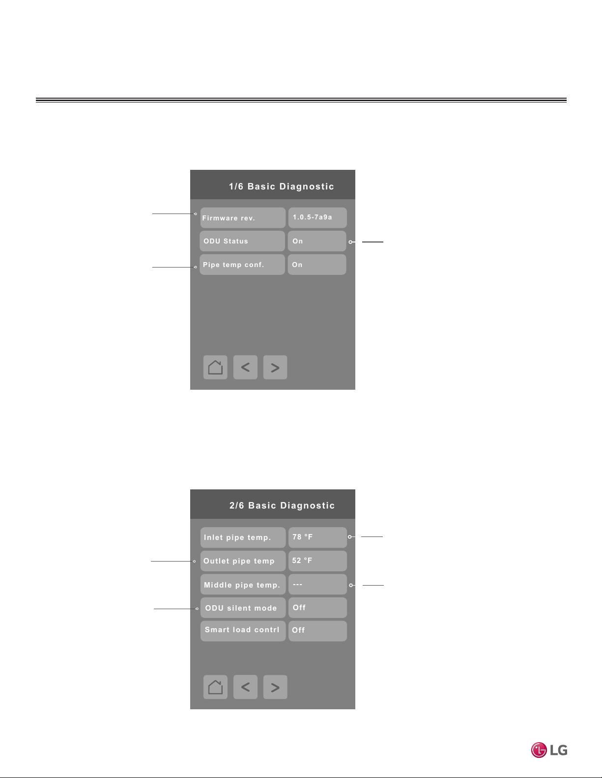
Press the Basic Diagnostic Button on the Configuration screen to display the Basic Diagnostic screen.
Firmware revision of the
controller
Outdoor Unit Status
Pipe temperature
configuration
Press the right arrow on the Basic Diagnostic screen to display the next Basic Diagnostic screen.
MultiSITE CRC 1 Controller
Outlet pipe temperature
Outdoor Unit Silent Mode
Status
Inlet pipe temperature
Middle pipe temperature
42
Due to our policy of continuous product innovation, some specifications may change without notification.
©LG Electronics U.S.A., Inc., Englewood Cliffs, NJ. All rights reserved. “LG” is a registered trademark of LG Corp.
Page 43
CONFIGURATION SCREENS
99 °F
50 °F
3/ 6 Basic Dia gnosti c
Cooling SP Max
Cooling SP Min
Heating SP Max
90 °F
Heating SP Min
40 °F
Off
4
4/ 6 Basic Dia gnosti c
ODU type
AddressLock
Wall-mount
IDU type
Basic Diagnostic – continued
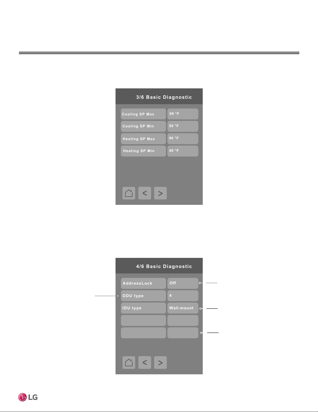
Press the right arrow on the Basic Diagnostic screen to display the next Basic Diagnostic screen.
User Interface Guide
Press the right arrow on the Basic Diagnostic screen to display the next Basic Diagnostic screen.
Outdoor unit type
ODU Given Add.
Filter Remain (Hrs)
0
1960
Address lock
Indoor unit type
Remaining filter time (hours)
Due to our policy of continuous product innovation, some specifications may change without notification.
©LG Electronics U.S.A., Inc., Englewood Cliffs, NJ. All rights reserved. “LG” is a registered trademark of LG Corp.
43
Page 44
CONFIGURATION SCREENS
0
0
5/ 6 Basic Dia gnosti c
Current Error Code
Previous Error Code
Error Code
000
0
0
0
6/ 6 Basic Dia gnosti c
Error Code
000
Error Code
Error Code
Oldest saved error
Basic Diagnostic – continued
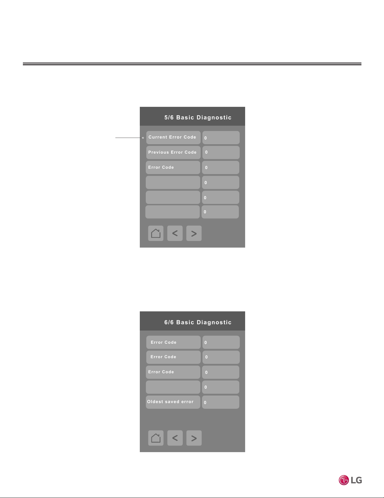
Press the right arrow on the Basic Diagnostic screen to display the next Basic Diagnostic screen.
Screens 5/6 Basic Diagnostic and 6/6 Basic Diagnostic display a historical
list of the 10 most recent
error codes generated by
the Indoor Unit. The most
recent error code appears
at the top of the list.
Error Code
Error Code
Error Code
Press the right arrow on the Basic Diagnostic screen to display the Basic Diagnostic screen.
MultiSITE CRC 1 Controller
Error Code
44
Due to our policy of continuous product innovation, some specifications may change without notification.
©LG Electronics U.S.A., Inc., Englewood Cliffs, NJ. All rights reserved. “LG” is a registered trademark of LG Corp.
Page 45
CONFIGURATION SCREENS
0
0
Password Setup
Config password
User password
Password Setup
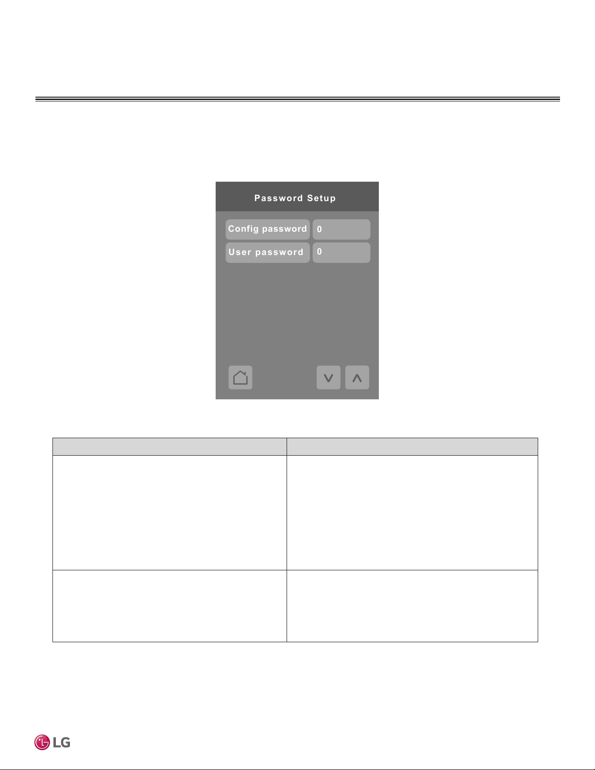
Press the Password Setup button on the Configuration screen to display the Password Setup screen.
User Interface Guide
Conguration Parameters Default Value Parameter Settings
Cong password
Default value = 0
User password
Default value = 0
Cong password
This parameter sets a protective access password to prevent
unauthorized access to the conguration menu parameters.
A default value of “0” will not prompt a password or lock the
access to the conguration menu. User must include any
leading “0” if anything less than a 4-digit code is selected
for a password. A default value of “0” will not prompt for a
password.
Range is: 0 to 9999.
User password
This parameter sets a protective access password to prevent
user unauthorized access to main screen adjustments. A
default value of “0” will not prompt for a password.
Range is: 0 to 9999.
Due to our policy of continuous product innovation, some specifications may change without notification.
©LG Electronics U.S.A., Inc., Englewood Cliffs, NJ. All rights reserved. “LG” is a registered trademark of LG Corp.
45
Page 46
CONFIGURATION SCREENS
Factory Default
Push to accept:
Are you sure?
Erase all?
No
No
Factory Default
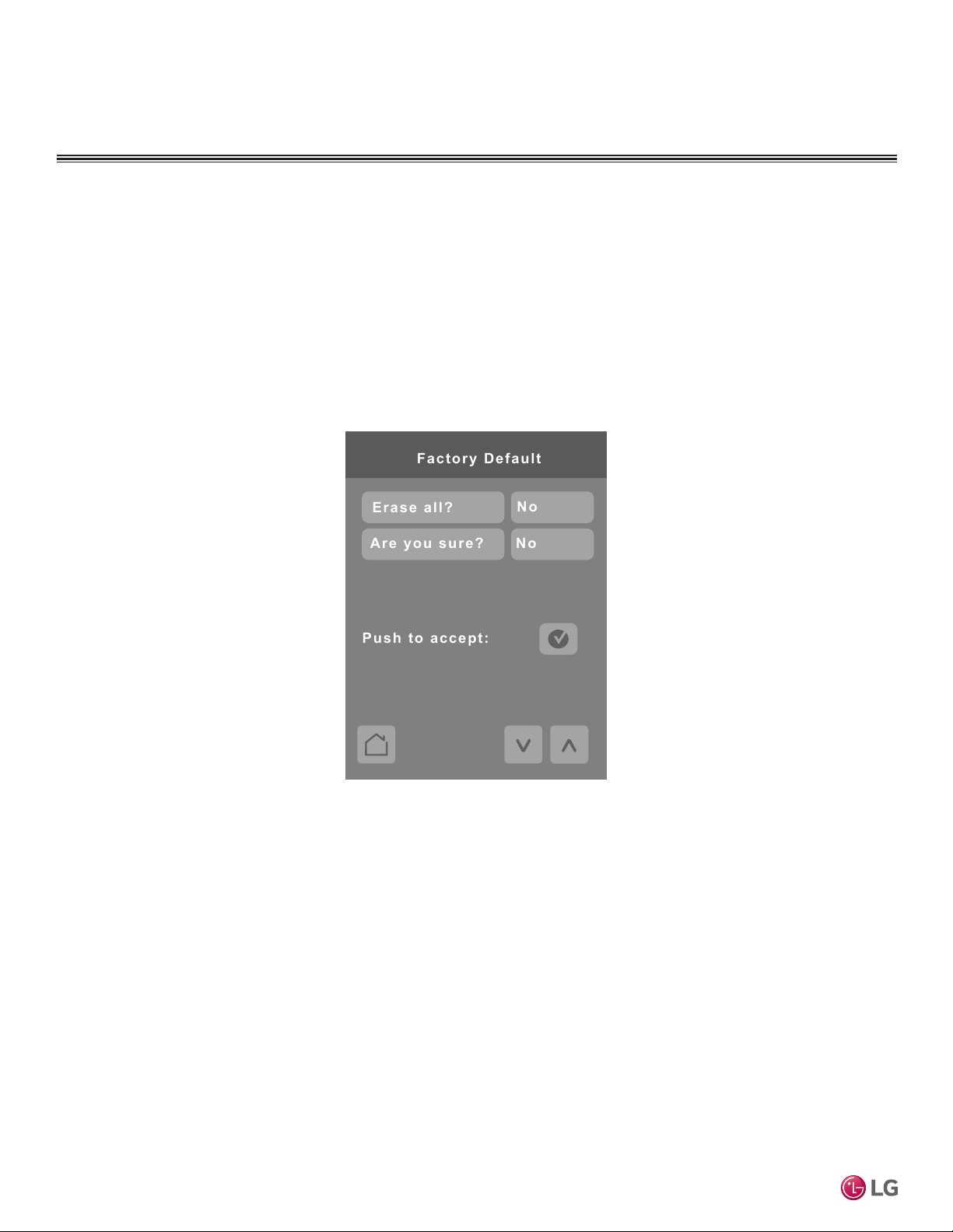
Answering Yes to both parameters and tapping ‘push to accept’ erases all values and sets the controller
to factory default values.
Note:
Once in the Factory Default screen, if user proceeds with this step, all schedules and current controller settings, along with time and date will be cleared. There is no way to recover settings once a Factory Default has
been performed.
MultiSITE CRC 1 Controller
46
Due to our policy of continuous product innovation, some specifications may change without notification.
©LG Electronics U.S.A., Inc., Englewood Cliffs, NJ. All rights reserved. “LG” is a registered trademark of LG Corp.
Page 47
CONFIGURATION SCREENS
Relative Humidity Display
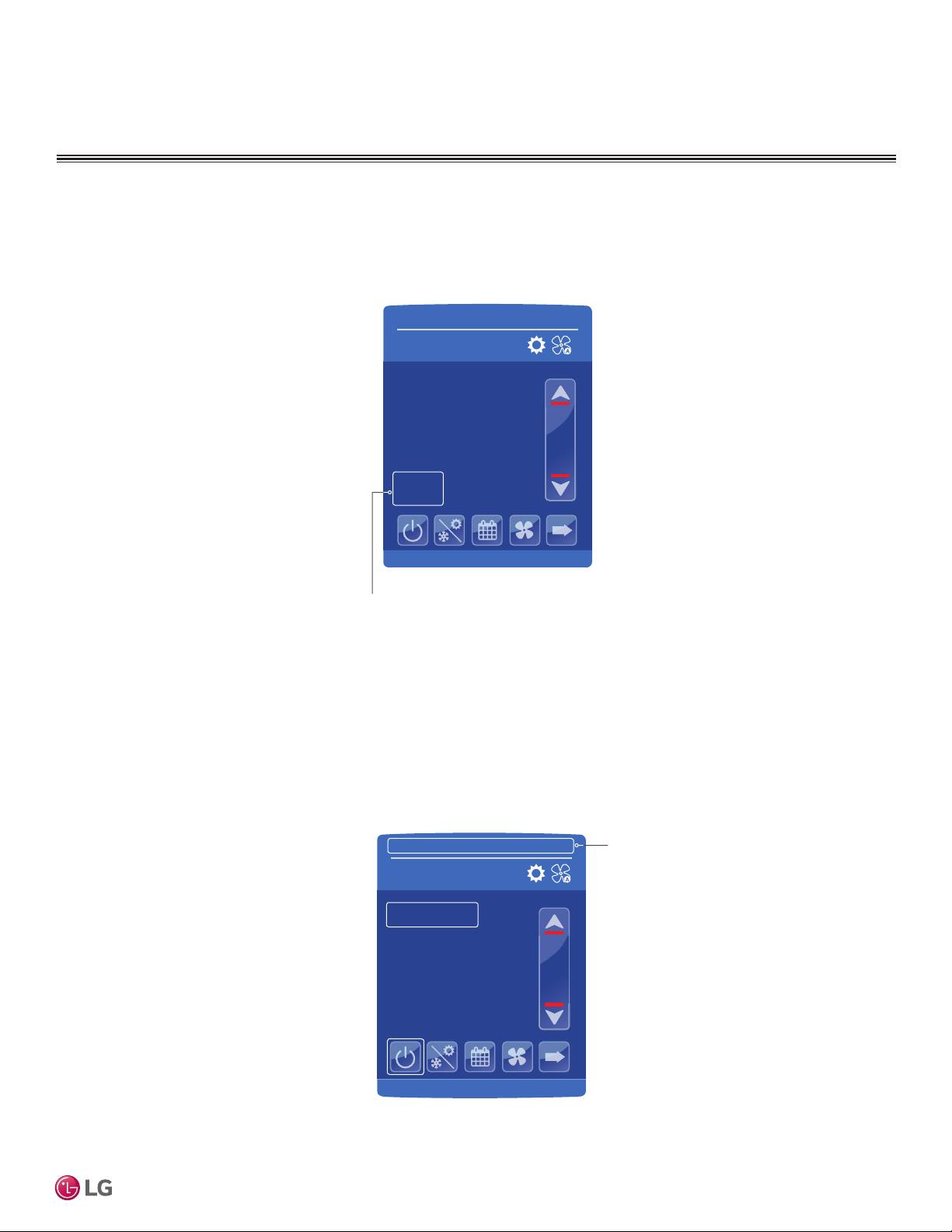
Relative humidity is displayed on the MultiSITE CRC1+ controller only. Apart from the visual indication of relative
humidity, this data is also available as a monitoring point via MSTP BACnet to be used by the user as desired.
45 %
Relative humidity
Time and Date
Time and date are displayed at the top of the home screen.
09-26-2017
Occ Auto Heat
Indoor °F
74°
Humidity
2:43 PM
75.0
User Interface Guide
09-26-2017
Occ Auto Heat
Indoor °F
74°
Humidity
45 %
Due to our policy of continuous product innovation, some specifications may change without notification.
©LG Electronics U.S.A., Inc., Englewood Cliffs, NJ. All rights reserved. “LG” is a registered trademark of LG Corp.
2:43 PM
75.0
Time and Date will display when
updated in display settings. Time
and Date must be reset if Controller
is set to factory default values.
47
Page 48

CONFIGURATION SCREENS
PIR (Motion Sensor)
The MultiSITE CRC1+ version of the controller comes with an onboard PIR style motion sensor. If the sensor is
enabled (installer configuration under Accessories), status from the PIR sensor will be used to control the operation of the IDU as follows:
If the IDU status is currently Occupied and the onboard PIR goes Unoccupied, the IDU will operate according to
the Setback values of the controller and will change its status to Unoccupied.
If the IDU status is currently Unoccupied and the onboard PIR goes Occupied, the IDU will operate according to
the settings in use during the last Occupied status and will change its status to Occupied.
If the IDU is currently in Setback or Override modes, information from the PIR sensor will be ignored.
MultiSITE CRC 1 Controller
48
Due to our policy of continuous product innovation, some specifications may change without notification.
©LG Electronics U.S.A., Inc., Englewood Cliffs, NJ. All rights reserved. “LG” is a registered trademark of LG Corp.
Page 49

Who to call for assistance
Freight Damage and Unit Replacements Your LG Manufacturer Representative
Missing Parts Your LG Manufacturer Representative
Freight Damage and Unit Replacements Your LG Manufacturer Representative
Received Wrong Indoor Unit Model Your LG Manufacturer Representative
Installation, Startup, and Commissioning Technical Assistance 1-888-865-3026
For warranty information, visit www.lghvac.com.
Page 50

LG Electronics
Commercial Air Conditioning Division
4300 Northpoint Parkway
Alpharetta, Georgia 30022
www.lghvac.com
LG Customer Information Center, Commercial Products
1-888-865-3026 USA
Follow the prompts for commercial A/C products and parts.
UM_CRC1_Series_Controllers_05_17
Supercedes: UM_CRC1_Series_Controllers_3_17
Supercedes: UM_CRC1_Series_Controllers_10_16
 Loading...