

Page 1
BRENTWOOD
Installation Instructions
This installation manual will help you
obtain a safe, efficient, dependable
installation for your fireplace and
chimney system. Please read and
understand these installation instructions
before beginning your installation.
CAUTION: Do not attempt to modify or
alter the construction of the fireplace or
its components. Any modification or
alteration of construction may void the
warranty, listings and approvals of this
system. In that case, Lennox Heart
product will not be responsible for
damages. Install the fireplace only as
described in these instructions.
PLEASE RETAIN THIS MANUAL
FOR FUTURE REFERENCE
WARNING: The fireplace cannot be
operated without a door. Consult your
dealer to select the correct door model of
your choice.
Listed to standards ULC-S610
UL-127
LENNOX HEARTH PRODUCTS
1110 West Taft Avenue, Orange, CA 92865, USA
Printed in Canada Rev. 04 Jan. 05 PIBRENTW-A
Page 2

TABLE OF CONTENTS
Page
1. SAFETY RULES ................................................................................................. 1
2. CERTIFICATION LABEL ................................................................................ 2
3. THE FIREPLACE ............................................................................................... 3
3.1 INTRODUCTION .................................................................................................................. 3
3.1.1 Parts Required
3.1.2 Additional Equipment (optional)
3.2 OPERATING THE BRENTWOOD ...................................................................................... 4
3.2.1 Fuel
3.2.2 First Fires
3.2.3 Building a Fire
3.2.4 Primary Air and Air Boost Controls
3.2.5 Accelerated Combustion
3.2.6 Medium Combustion
3.2.7 Slow Combustion
3.2.8 Refuelling For Best Performance
3.2.9 Smoking – Causes And Troubleshooting
3.3 MAINTAINING YOUR BRENTWOOD ............................................................................... 8
3.3.1 Creosote
3.3.2 Chimney Maintenance
3.3.3 Top Baffle Removal Prior to Cleaning The Chimney
3.3.4 Dealing With a Chimney Fire
3.3.5 Finish Door Casing Care
3.3.6 Ashes
3.3.7 Refractory Installation
3.3.8 Door Installation
3.3.9 Door Adjustment
3.3.10 Glass Care – Replacement
3.3.11 Glass Care – Cleaning
3.3.12 Gasket Replacement
3.4 FIREPLACE INSTALLATION ............................................................................................ 12
3.4.1 Locating The BRENTWOOD
3.4.2 Hearth Extension Requirements
3.4.3 Framing, Facing And Mantel
3.5 HOT AIR DUCTING INSTALLATION .............................................................................. 16
3.5.1 Gravity Kit
3.6 OUTSIDE AIR KIT ............................................................................................................... 19
3.6.1 Outside Air Kit Installation
3.6.2 Chimney Outside Air Kit Installation
4. THE CHIMNEY .................................................................................................... 21
4.1 CHIMNEY INSTALLATION NOTES ................................................................................. 21
4.2 CHIMNEY INSTALLATION INSTRUCTIONS ................................................................. 22
4.3 OFFSET CHIMNEY INSTALLATION .............................................................................. 25
4.4 ANGLED WALL RADIATION SHIELD ............................................................................ 27
4.5 CHIMNEY SUPPORTS INSTALLATION .......................................................................... 28
4.6 MULTIPLE TERMINATIONS ............................................................................................ 28
5. PARTS AND COMPONENTS LIST ................................................................. 30
6. OPTIONS ............................................................................................................. 31
7. APPENDIX (Specifications, Clearances, Replacement Parts) ........................ 32
ii
Page 3

1. SAFETY RULES FOR OPERATING YOUR
FIREPLACE MODEL BRENTWOOD
• Use only a Lennox Hearth Products glass door, specifically designed for the model
BRENTWOOD fireplace.
• When cleaning the fireplace, the ashes should be placed in a metal container with a tight
fitting lid. The closed container of ashes should be placed on a non-combustible floor or
on the ground outside the house, pending final disposal. If the ashes are disposed of by
burial in soil or otherwise locally dispersed, they should be retained in the closed
container until all cinders have thoroughly cooled.
Caution: Never use gasoline, kerosene, charcoal lighter fluid or similar liquids to start
or rekindle a fire in this fireplace. Keep all such liquids well away from the
fireplace at all times.
Caution: Keep combustible materials at least 48 inches away from the front of the
fireplace opening.
Caution: Never leave children unattended when there is a fire burning in the fireplace.
WARNING: THIS FIREPLACE HAS NOT BEEN TESTED WITH AN UNVENTED OR
VENTED GAS LOG SET. TO REDUCE RISK OF FIRE OR INJURY, DO
NOT INSTALL AN UNVENTED GAS LOG SET INTO THIS FIREPLACE.
1
Page 4
2. CERTIFICATION LABEL
2
Page 5

3. THE FIREPLACE
3.1 INTRODUCTION
The BRENTWOOD fireplace is an energy efficient, heat circulating, close combustion
fireplace. You will receive a lifetime of comfort and enjoyment from your fireplace
provided it is installed, maintained and operated properly.
• Please read these instructions and retain this manual for future reference.
• Before beginning the fireplace installation, consult the local authorities to obtain your
building permit and check your local building codes. Install the fireplace only as
described in these instructions and using only Lennox Hearth Products components.
• The BRENTWOOD is not intended for use with a gas log. Failure to follow these
instructions will void the certification and the warranty of the fireplace and may result in
an unsafe installation.
3.1.1 Parts Required
• Fireplace model BRENTWOOD
• 6" diameter chimney model AC manufactured by Security Chimneys International only,
including:
- Chimney lengths
- Elbows (where necessary)
- Associated components as per these installation instructions
3.1.2 Additional Equipment (optional)
• Gravity venting system
• Outside air kit
• AC chimney outside air kit
• Panel for clean face option (only with gravity venting system)
• Rigid firescreen
• Fireplace fan kit
3
Page 6

3.2 OPERATING THE BRENTWOOD
3.2.1 Fuel
The BRENTWOOD is designed to work best when fuelled with seasoned cordwood.
Hardwoods are preferred to softwoods since the energy content of wood is relative to its
density. Hardwoods will result in a longer burning fire and less frequent refuelling. A
moisture content of 15% to 20% (seasoned) is recommended. Wood that has been cut and
split and let to dry under a cover for a period of one year will usually meet that criteria.
Excessively wet wood will be difficult to burn and will result in lower efficiency, increased
creosoting and deposits on the glass and in the chimney. Excessively dry wood will burn
well but will also have higher emissions and shorter burning time.
Do not burn scrap or garbage, treated wood or wood such as driftwood from the ocean which
has been exposed to salt or other chemicals. Salt or chemicals can corrode the firebox and
chimney. Do not burn large amounts of paper, cardboard, Christmas tree branches or
building construction materials. Intense firing with these materials may overheat the
fireplace, causing damage to the unit, a fire or even possibly igniting a chimney fire if the
chimney is creosoted.
3.2.2 First Fires
Before using the fireplace make sure to remove the plastic wrapping on the door. Remove all
remaining glue with mild soap.
The first 5 or 6 fires should be small fires of short duration (about 30 to 60 minutes).
This will help cure the refractory bricks. The first fires may produce slight smoking due to
drying of the paint and steel and any dust accumulated on the fireplace will burn off at this
time. It may set off a smoke alarm located in the same room. For this reason the room
should be well ventilated for the first few fires.
3.2.3 Building a Fire
To start a fire, place several crumpled up balls of newspaper in the firebox. Place small dry
pieces of kindling on top of the paper, criss-crossing the kindling so that there are air spaces
in between. Keep the fuel far back enough so that air can get underneath. Open the air
controls fully and light the newspaper. Once the newspaper and the kindling is well ignited,
close the door. Once the kindling fire is well established, cordwood can be added. (see
Primary Air Combustion Control section for proper operation of the air controls)
The unit will burn best with 2-3 pieces of cordwood spaced 1 to 2 inches apart and allowing
air to get under the fuel. Criss-crossing or arranging the fuel so that air can get underneath,
will help the fire to get started easily. The unit should be operated with the air control fully
open long enough to get the cordwood well ignited.
4
Page 7
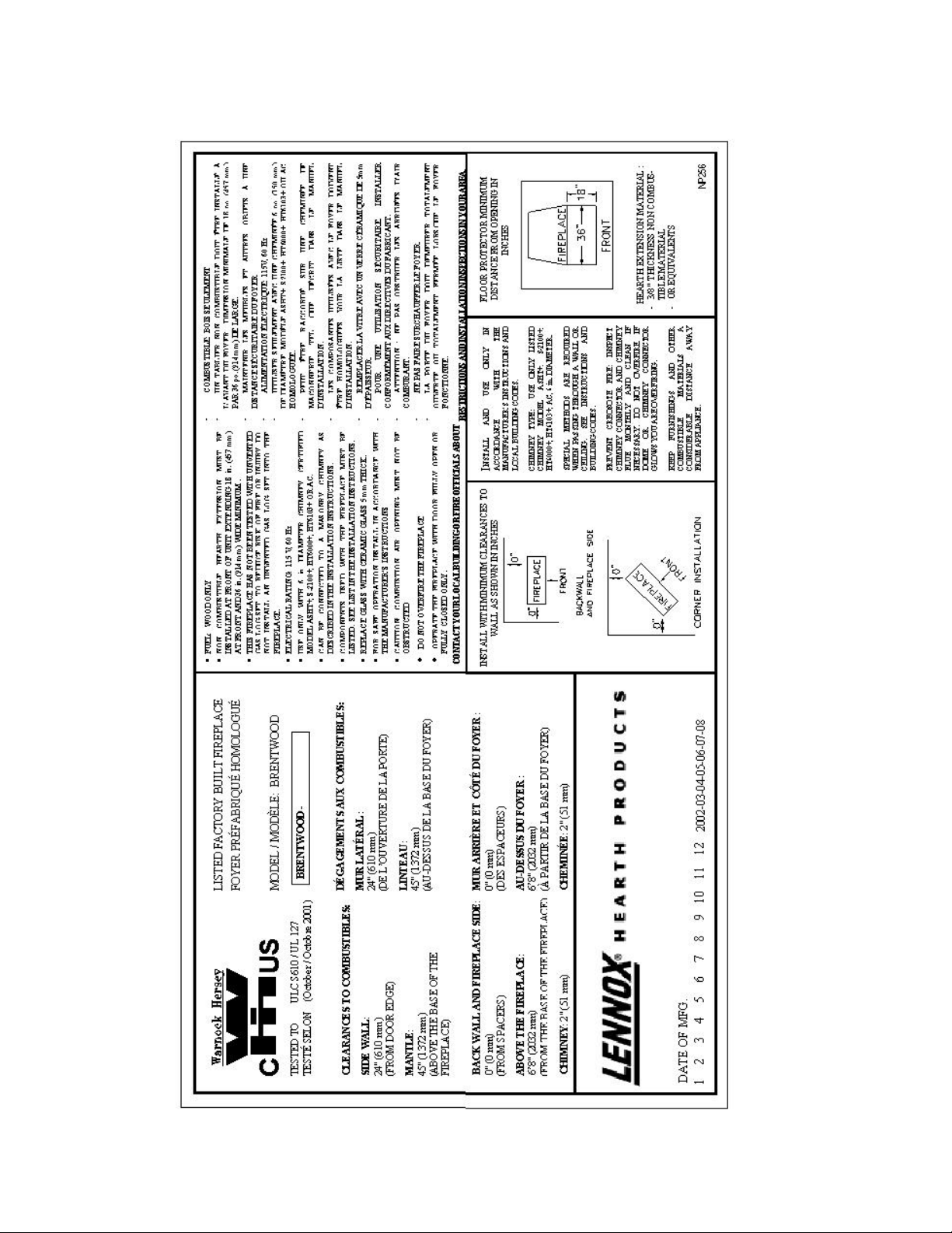
3.2.4 Primary Air and Air Boost Controls
There is no flue damper in the BRENTWOOD. As is common with air tight stoves, the
combustion air control sets the flow of air entering the firebox. This allows for a more
precise control of the fire. The combustion air control is located below the door on the left
side. The main source of air (primary air) entering the firebox can be diminished by moving
the air combustion control from left to right. The primary air is fully opened when the air
control is completely moved to the left. The air control device can also be used to add an
extra boost of air especially during fire start up and reloading of the unit. Pulling the air
combustion control will induce an air boost at the base of the fire allowing an easier fire start
up. When the fire is well established, the control can be pushed forward to shut down the air
boost allowing for a longer burn time. The combustion air control should be in the closed
position (primary air and air boost) when the fireplace is not in use. This will minimize air
leakage up the chimney. The combustion air control should be opened before opening the
door to minimize the possibility of back draft coming into the room.
Figure 1
3.2.5 Accelerated Combustion
The maximum heat output for the BRENTWOOD is achieved by burning with the door
closed and the combustion air opened and pulled back. By this method, the BRENTWOOD
can produce up to 55,000 BTU of heat per hour. However, it will be necessary to reload with
wood every one or two hours. This is the least efficient method of burning the
BRENTWOOD.
Use caution when firing with the combustion air control wide open. Only burn cordwood in
this manner. Small dry pieces of softwood and construction scraps will burn very intensely
using this method and may damage the firebox.
5
Page 8

3.2.6 Medium Combustion
This is the recommended mode of operating the BRENTWOOD and should be the one
normally used since it will deposit the least amount of creosote on the glass and in the
chimney. The combustion air control must be 3/4 closed and pushed forward to close the air
boost. The precise setting will depend on many factors, including chimney length and the
moisture content of the wood.
For instance, a long chimney will necessitate closing the damper more. To obtain the proper
combustion, close the damper completely, then open it about 1/4" to 1/2". Three medium
size pieces of wood should be burning on a bed of hot coals. The heat output will be
approximately 30,000 BTU per hour and the loading time will be about every 3-4 hours.
Softwoods may be burned using this method but the time will be substantially reduced.
3.2.7 Slow Combustion
When the air combustion control is completely closed, the fireplace is in a slow combustion
phase. If the hearth is hot enough, slow combustion will not stop the fire, but there will be a
noticeable change in the flame pattern. The flames will be slow and may appear dirty if the
wood is too wet (moisture content of 20% and more). Do not allow the wood to burn without
flame, since this will produce excessive creosote in the unit.
Creosote may accumulate on the glass door. This method of burning should be used only
after operating the BRENTWOOD with the air control opened to produce a hot fire for about
an hour or at medium pace for at least 3 hours. Slow combustion can be used at night in order
to reduce the heat output and to prolong the burn. The loading time will be between 6-8
hours.
3.2.8 Refuelling For Best Performance
The BRENTWOOD fireplace will operate best if attention is given to operating the unit with
the damper fully opened after refuelling in order to bring the firebox and the chimney system
up to their optimum operating temperature. Combustion efficiency is relative to firebox
temperature. A temperature of 500º C and up, with a visible flame, in the upper part of the
firebox indicates a maximum efficiency. To obtain this temperature, the fireplace must be
operated with the primary air and air boost controls fully opened during 10 to 20 minutes
after reloading, depending on the heat and on the moisture content of the wood. Once you
have reached the desired temperature, the air boost can be closed and the primary air set to a
medium setting. You know you have reached the desired temperature when, closing the
primary air control, you can see a flame at the top of the firebox. The benefit of this
technique will be cleaner glass, less creosoting, greater efficiency and the most pleasing fire
for your enjoyment. If your fireplace is equipped with a central forced air system, make sure
the central blower is turned off during reloading to avoid smoking problems.
6
Page 9

3.2.9 Smoking – Causes and Troubleshooting
To reduce the likelihood of smoking when opening the door, set the combustion air controls
to the left before opening the door. Your fireplace has been designed and tested to provide
smoke free operation. Occasionally, there may be a small amount of smoking upon lighting
the fire, until the chimney heats up but this should not continue. If the fireplace continues to
smoke it is probably for one of the following reasons:
A. Negative pressure in the house
As the fire burns, air goes up the chimney. This air must be replaced through leakage
into the house or through the outside air duct. When operating the BRENTWOOD, open
a nearby window temporarily to check if there is adequate air supply replacement.
B. Fans operating (e.g.: range hood)
These fans draw air out of the house and may actually cause a negative pressure in the
house. Turn off all fans and open a nearby window to determine if this is the cause of the
problem.
C. Wet wood
Wet or tarred wood will smoulder and smoke instead of burn properly.
D. Dirty or blocked chimney
Check to make sure the chimney is clear and clean.
E. Chimney not long enough
The minimum chimney height is 12 ft. not including the fireplace height. The chimney
must extend at least 3 feet (915 mm) above its point of contact with the roof and at least 2
feet (610 mm) higher than any roof or wall within 10 feet (3 m) of it. When installed
with offsets, the minimum chimney height is 15 ft. Additional height will increase
draught and will decrease the tendency to smoke.
F. Poor chimney draft
With no fire, there should be sufficient draught to exhaust cigarette smoke introduced
under the baffle. Chimneys installed against an outside wall without protection may
generate back draught problems which will cause start-up problems. To prevent this,
open a nearby window, roll up a piece of paper and light it. Then, hold it in the upper
part of the firebox to warm up the chimney. Wait until the draught is sufficient, then start
the fire.
G. Blower for central forced air kit operating
Make sure that the blower is at the "off" position when you open the fireplace door for
reloading.
7
Page 10

IMPORTANT NOTES
A. Do not block the hot air vents to the fireplace as this will cause the fireplace to overheat.
B. Never start a fire using gasoline, kerosene, charcoal lighter fluid or any other combustible
liquid.
C. Do not burn coal. The sulphur in coal will corrode the firebox.
D. Do not burn driftwood which has been in the ocean or salt water. The salt will corrode
the firebox and chimney.
E. Do not burn wood in the area in front of the grate.
F. Do not abuse the unit by burning paper, or cardboard or construction material such as
pressed wood, plywood or lumber.
G. Do not allow the wood to smoulder or burn without flame, since this will produce
excessive creosote in the unit.
3.3 MAINTAINING YOUR BRENTWOOD
3.3.1 Creosote
When wood is burned slowly without a flame, it produces tar and other organic vapors which
combine with expelled moisture to form a black deposit called creosote which accumulates
on the flue lining. When ignited, this creosote makes an extremely hot fire. If the creosote
accumulation is large, a creosote fire in the chimney can damage the chimney and overheat
the surrounding wood framing. Creosote formation in a chimney can be minimized by
making sure there is always visible flame burning, avoid smouldering fires and by proper
refuelling techniques.
3.3.2 Chimney Maintenance
Regular chimney inspection and maintenance combined with proper operation will prevent
chimney fires. Keep your chimney clean. Do not allow more than 1/16" creosote build up in
your chimney. The amount of creosote will depend on variables such as frequency of use
and type of fire. We recommend that you:
A. Initially inspect the chimney system weekly. From this, you will learn how often it will
be necessary to clean your chimney.
B. Have your chimney cleaned by a qualified chimney sweep. If you wish to clean it
yourself, we recommend using a stiff plastic or non-metallic brush. If a metal brush is
used, its size should be slightly smaller than the flue to avoid damaging the chimney. Do
not use a brush that will scratch the stainless steel interior of the chimney.
C. Do not expect chemical cleaners to keep your chimney clean. The rain cap can be
removed for inspection and/or cleaning of the chimney.
8
Page 11
3.3.3 Top Baffle Removal Prior to Cleaning The Chimney
Before starting to clean your chimney, we recommend that you remove the top baffle to
avoid creosote dust collection at the top of the baffle. Follow these steps to set the top baffle
out of the way:
1. Remove the side refractory holder. They are located at the top of the refractory.
2. Lift the front baffle.
3. Slide the back baffle under the front baffle. You now have access to the chimney.
3.3.4 Dealing With a Chimney Fire
Regular chimney maintenance and inspection can prevent chimney fires. If you have a
chimney fire, follow these steps:
1. Close the fireplace door and the combustion air controls.
2. Alert your family of the possible danger.
3. If you require assistance, alert your fire department.
4. If possible, use a dry chemical fire extinguisher, baking soda or sand to control the fire.
Do not use water as it may cause a dangerous steam explosion.
5. Check outside to ensure that sparks and hot embers coming out of the chimney are not
igniting the roof.
6. Do not use the fireplace again until your chimney and fireplace have been inspected by a
qualified chimney sweep or a Fire Department Inspector.
3.3.5 Finish Door Casing Care
Use a glass cleaner and a soft cloth to polish the casing. Do not use abrasives such as steel
wool, steel pads or an abrasive polish for they may scratch the casing’s finish.
3.3.6 Ashes
Remove ashes only when the fire is out and the ashes are cold (24 to 48 hours after the fire is
out).
9
Page 12

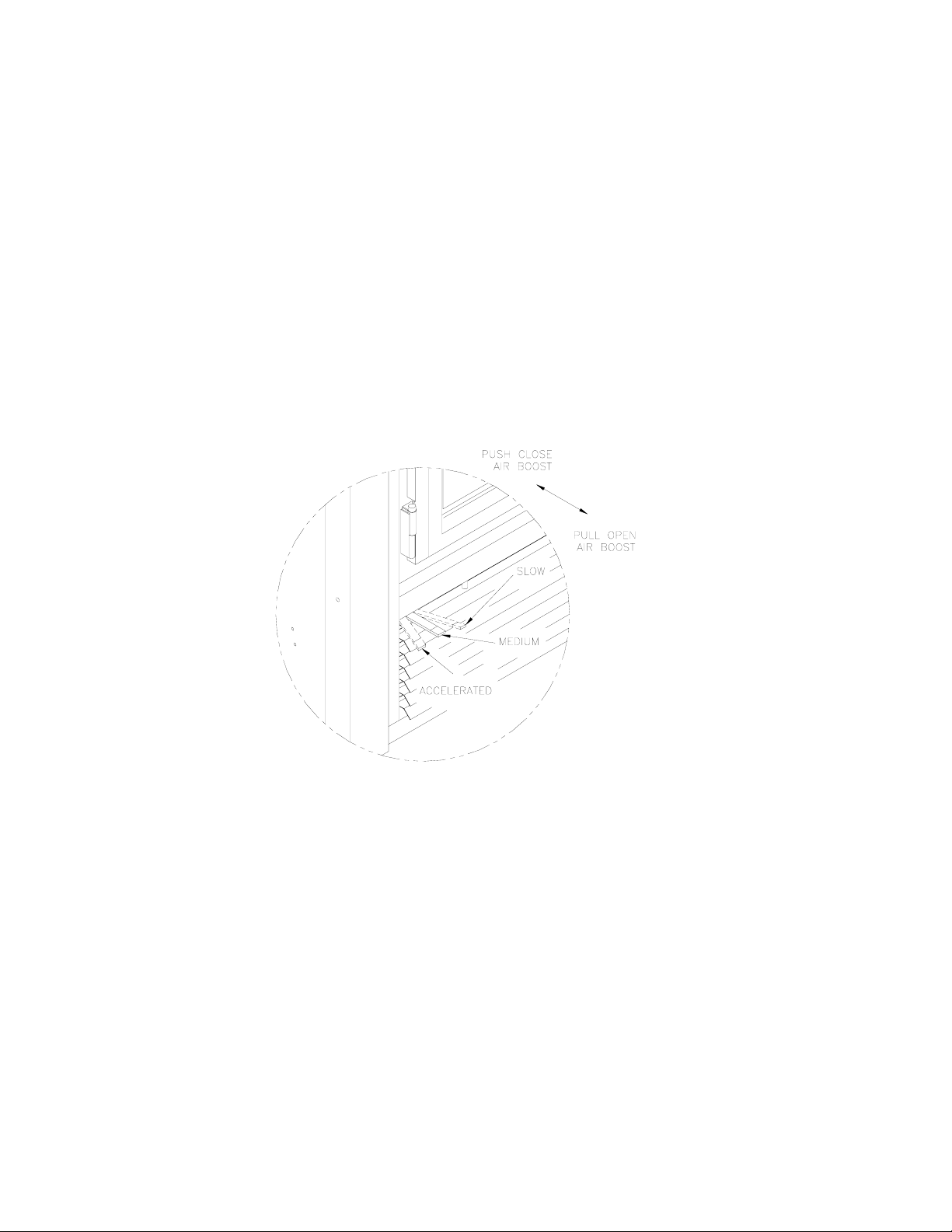
3.3.7 Refractory Replacement
The intense heat of the fire will normally cause hairline cracks in the refractory. These
cracks can be minimized by proper curing as described in "First Fires". They will not
normally diminish the effectiveness of the refractory. If large cracks develop, then the
refractory should be replaced. To replace the refractory bricks, follow these steps:
1. Remove the front refractories
2. Remove the bottom refractory
3. Remove the left side refractory
4. Remove the right side refractory
5. Remove the back refractory
6. Remove the front ceramic baffle
7. Remove the rear ceramic baffle
To install the new refractories, follow
the above steps in reverse.
Figure 2
3.3.8 Door Installation
The door must be installed only when
the installation of the BRENTWOOD
is completed. All you have to do is fit
the male part of the hinge, already on
the door, to the female part, which is
on the fireplace.
To remove the door, simply pull the
door up from the hinges.
The door adjustment has been set at
the factory. If the fit is still not
perfect, you can adjust the door using
the hinge screws.
Figure 3
10
Page 13

3.3.9 Door Adjustment
The door may need to be adjusted to
be completely airtight. The gaskets’
air-tightness can be adjusted using the
adjustment screw located on the right
side of the fireplace façade. (An Allen
key #1/8 – not supplied - will be
necessary for this adjustment)
3.3.10 Glass Care - Replacement
The glass used for the BRENTWOOD is a high temperature ceramic glass (1400° F). If the
glass breaks, it must be replaced with an identical ceramic glass. Tempered glass or ordinary
glass will not withstand the high temperatures of the BRENTWOOD. Replacement glass
should be purchased from a Lennox Hearth Products dealer (see “Replacement Parts”, page
34). Do not operate the unit with cracked or broken glass.
Figure 4
3.3.11 Glass Care - Cleaning
The BRENTWOOD is designed to keep the glass clean under normal operating conditions. If
the BRENTWOOD is operated continuously with the combustion air controls closed, the
glass will tend to get dirty unless the fuel, firebox and glass are maintained at hot
temperatures (see "Refuelling For Best Performance”). To clean the glass, there are a
number of specially designed cleaners. Your authorized Lennox Hearth Products dealer can
recommend a suitable cleaner which is available in your area. Regular household glass
cleaners will not clean creosote. Do not use abrasives such as steel pads, steel wool or oven
cleaner as they will scratch the glass.
3.3.12 Gasket Replacement
Remove the door from the unit (see page 10) and lay it on a clean unabrasive surface. To
replace the gasket, first remove all of the old gasket and gasket cement. Make sure that the
surface is totally clean before applying new cement (a high temperature silicone caulking
rated at 500°F, 260°C, is suitable) or adhesion problems may result. Apply gasket cement to
the gasket channel and install the new gasket. This replacement part is available from your
Lennox Hearth Products dealer in the following dimensions:
Gasket
Around glass 69" 5/16" dia.
On door frame 73" 5/8" dia.
Length Dimensions
11
Page 14

3.4 FIREPLACE INSTALLATION
3.4.1 Locating The BRENTWOOD
A. The best location to install your fireplace is determined by considering the location of
windows, doors, and the traffic flow in the room where the fireplace is located, allowing
space in front of the unit for the hearth extension and the mantel, and taking into
consideration the location of the hot air ducts (optional), outside air kit and chimney. If
possible, you should choose a location where the chimney will pass through the house
without cutting floor or roof joists (see fireplace dimensions page 13).
B. Usually, no additional floor support is needed for the fireplace. The adequacy of the
floor can be checked by first estimating the weight of the fireplace system. Weights are
given in the appendix. Next, measure the area occupied by the fireplace which is
normally 36" X 24 ½". Note the floor construction and consult your local building code
to determine if additional support is needed.
C. The BRENTWOOD may be installed directly on the floor or on a raised base (for proper
guidelines, refer to "Hearth Extension Requirements") and a minimum of 6'8"
measured from the base of the appliance to the ceiling is required.
3.4.2 Hearth Extension Requirements
The BRENTWOOD may be installed directly on a combustible floor; however, the
combustible floor in front of the fireplace must be covered with a non-combustible material
(tile, marble, stone, etc.).
Figure 5
12
Page 15

3.4.3 Framing, Facing And Mantel
The construction of the framing, facing, and mantel must be in accordance with the standards
and the following illustrations (figures 6 to 10):
A. Frame the fireplace using 2" x 3" or heavier lumber.
B. WARNING
fireplace, except for the studs above the facade that support the facing and mantel. This
area must remain empty for a height of 6'8" (2032 mm)
appliance.
C. Frame the fireplace with vertical studs at the sides of the fireplace running from floor to
ceiling (see figure 8). If combustible facing is to be used, position the studs back, from
the front edge of the fireplace, a space the thickness of the facing material so that the
facing can be installed flush with the fireplace facing. Frame headers between the
vertical studs only as follows:
- Place 2" x 3" or 2" x 4" headers, only along the upper part of the front, side and back
faces. Do not put wood or any combustible material within the area above the
fireplace except on the front facing.
- Place headers only as required to support the facing and mantel.
D. WARNING: The fireplace must not be in contact with any insulation or loose filling
material. Cover the insulation with gyproc panels around the fireplace.
: Combustible materials cannot be used in the space directly above the
measured from the base of the
Figure 6
Figure 7
Figure 8
13
Figure 9
Page 16

INSULATED CHASE CONSTRUCTION
Figure 10
14
Page 17

Facing
1. Combustible material must be installed flush with the fireplace. It may not project in
front of and on the fireplace (i.e. the steel façade of the fireplace) (figure 11).
2. Non-combustible materials such as brick, stone or ceramic tile may project in front of
and onto the fireplace facing (figure 12).
Mantel
The mantel must be installed at least 45" (1143 mm) above the base of the fireplace (figure
11).
Figure 11
Figure 12
15
Page 18

3.5 HOT AIR DUCTING INSTALLATION
Different hot air ducting systems can be installed with the BRENTWOOD:
- Gravity kit
- Forced air kit
-
3.5.1 Gravity Kit
Two kits are available:
1. Single hot air outlet including: (see Fig.13)
- 2 6" lengths 8" I.D.
- 1 hot air outlet kit (box, louver and frame)
- 2 adaptors
NOTE : To install the single hot air outlet, the chimney must be offset towards the back
using 2 – 30 deg. elbows back to back on the fireplace.
See components list page 30.
The only fan that can be used with the gravity kit is the UZY3.
The gravity kit allows you to block the upper louver of the fireplace. To do so, follow the
steps below:
a) Remove the upper louver from the fireplace.
b) Install the black panel (BWCF) making sure that the insulation strip is installed inside.
c) The fireplace façade can be covered with non-combustible material (fig. 17).
2. Double hot air outlet including: (See Fig.14)
- 2 telescopic lengths 8" I.D.
- 2 90º elbows 8" I.D.
- 2 hot air outlet kits (grill and frames)
- 2 adaptors
Figure 13 Figure 14
The safety rules for hot air ducting gravity kit installations are the following:
Minimum height* 68" (1727 mm)
Maximum length See figures 15 & 16
* The height of the louver must be measured from the base of the BRENTWOOD to the
middle point of the louver.
16
Page 19

The single outlet system is designed to be installed either flush with the front of the
BRENTWOOD or extended out slightly from the face of the fireplace (if installing with a
brick or thick facing for example). To extend the double outlet system, it will be necessary
to purchase two adjustable lengths (7B26ZL2A). To extend the single outlet, it is necessary
to install the insulation strip provided with the system. A maximum of 3 ½" (89 mm) of
extension is provided by the single outlet system (see figure 16).
When installing the double outlet system, the hot air outlets can be installed in the same
room as the fireplace, or one or both of the outlets can be installed in adjacent or upper
rooms. Installing the ducts at different elevations will tend to exhaust more heat out of the
higher outlet (figure 15).
Figure 15 Figure 16
Figure 17
17
Page 20

The duct system must be installed respecting the following:
1. Remove the plates closing up the 8" dia. holes on top of the fireplace. Then, cut the
insulation in order to obtain two 8" dia. openings. Fix the adaptors on the fireplace
openings by turning clockwise (figures 13 and 14).
2. Maintain at least a 2" (50 mm) clearance between the ducts and any combustible
material; the required hole size is 13" x 13" (330 mm x 330 mm).
Exception #1: For the grills, the framing can be 10 ¾" x 10 ¾" (275 mm x 275 mm) to
provide the clearance as required by the integral spacers on the double outlet duct system.
Exception #2: For the single outlet, the framing must be 8 ¼" x 32 ¼" (210 mm x 820
mm) or as required by the integrated spacers. At no time should any combustible facing
material such as panelling cover over any part of the grill face.
3. The maximum number of elbows in a run of duct is two.
4. Maintain at least 6 ½" (160 mm) clearance from the outlet grill framing to a combustible
ceiling, side wall or mantel.
5. When traversing a combustible wall or floor, a firestop must be installed at the wall or
floor penetration. The hole size must be 13" X 13". (330 mm x 330 mm)
6. Do not connect the hot air ducts to a central heating system. Malfunction of the heating
system’s fan will cause the fireplace to overheat. A furnace duct is only single wall and
not double wall as is required for the BRENTWOOD hot air exhaust. For this type of
installation refer to “Central Forced Air Kit” on the next page.
7. Use only Lennox Hearth Products grills and components as described in this manual.
Other grills or registers, for example, may be too restrictive and may overheat the
fireplace or ceiling.
8. Do not use insulated flexible ducts as they will overheat.
9. Do not use tees or any other components than the ones specifically listed here.
10. All ducts must extend upwards or horizontally. Never route the ducting downwards
11. The hot air outlet grills must be installed with the louvers pointing downwards in order to
prevent overheating adjacent ceilings.
12. Always install the two outlet grills when using the double hot air outlet kit and blocking
the upper louver of the fireplace.
.
18
Page 21

3.6 OUTSIDE AIR KIT (Optional)
During operation, the fireplace requires fresh air for combustion and draws air out of the house.
It may starve other fuel burning appliances such as gas or oil furnaces. As well, exhaust fans
may compete for air, causing negative pressure in the house, resulting in smoke entering the
house from the fireplace. This situation is aggravated in modern airtight houses. To overcome
this problem, we strongly recommend that you install an outside air assembly. Check with
local authorities having jurisdiction in your area, it may be mandatory.
NOTE: Should you decide not to install the outside air assembly, proceed as follows:
- Remove the bottom grill. The air box is located on front left and is on a slant.
- Unscrew the four screws holding the inside air box covering plate and remove it.
3.6.1 Outside Air Installation
The outside air assembly may be installed according to the following requirements :
A) Duct length should be kept to a minimum. The maximum length of duct is 20 ft.
(6.1 m) for a 4 in. dia. pipe (See note below).
B) The air intake register must not be installed more than 10 ft. (3050 mm) above the base of
the fireplace.
C) The fresh air must come from outside the house. The air intake must not draw air from
the attic, from the basement or garage.
D) The air intake should be installed where it is not likely to be blocked by snow or exposed
to extreme wind and away from automobile exhaust fumes, gas meters and other vents.
E) The duct and register may be installed above or below floor level.
The following components are required : - Outside air kit (UZI)
- 4" adapter for fireplace connection (supplied
with the unit)
Make a 4 ¼" (110 mm) hole in the outside wall of the house at the chosen location. From
outside, place the outside air register in the hole (open side down) and fasten the register to
the wall, with screws as shown (see figure 18). Slip the pipe into the insulated sleeve. Place
the insulated pipe over the register tube and over the fireplace’s outside air connector (see
figure 19). At each end, carefully pull back the insulation and plastic cover exposing the
flexible pipe. Using the aluminium tape provided, wrap the tape around the joint between
the flexible pipe and the air inlets. Carefully push the insulation and plastic cover back over
the pipe. Using aluminium tape, fasten the plastic cover in place.
NOTE: We recommend not to exceed 20 feet of 4” flexible pipe. If you require a longer
length we recommend that you use a 5” diameter flexible pipe for the complete run up to 30
feet and a 6” diameter pipe for a run of up to 40 feet.
19
Figure 18 Figure 19
Page 22

3.6.2 AC CHIMNEY OUTSIDE AIR KIT (Optional)
* The outside air assembly for the AC (Air Cool) chimney is mandatory in some areas.
Check with your local building authority for the requirements in your area.
All required parts for outside air assembly are contained in the following kit: ACZIB
1) Install the outside air kit box and collar on the top of the unit. Install the flex 4" adaptor on
the top of the outside air kit box.
2) Install the outside air register as described in the preceding section (3.6.1). Connect the
outside air register to the 4" flex adaptor with the flex pipe. Respect the installation
guidelines A) to E) from the preceding section (3.6.1).
Figure 20
Chimney outside air kit installation
20
Page 23

4. THE CHIMNEY
4.1 CHIMNEY INSTALLATION NOTES
1. Always install an interior chimney as it will provide better performance. In areas with
continuous temperatures below -18° C (0° F), the use of an exterior chimney increases the
likelihood of operating problems such as low draught, high rate of creosoting, and poor
start-up characteristics. Exterior chimneys are also prone to down drafting and flow
reversal. Installations, which are located on lower floors in the house, such as in a
basement, in combination with outside chimney, are especially prone to flow reversal. If
interior installation is impossible, install an AC chimney enclosed in an insulated chase.
2. The Security fireplace model BRENTWOOD can only be install with Security Chimneys
International Ltd 6" diameter model AC (Air Cool) chimney system.
3. A chimney venting a fireplace shall not vent any other appliance.
4. The minimum chimney height is 12 ft. (3.7 m). In altitude, add 18" (450 mm) to the
chimney for every 2000 feet (600 m) above sea level.
5. All chimney installations must include at least one support. The maximum length of
chimney that can be supported by the fireplace is 26 ft. (8 m).
6. The chimney must extend at least 3 ft. (915 mm) above its point of contact with the roof
and at least 2 ft. (610 mm) higher than any wall, roof or building within 10 ft. (3m) of it
(Figure 21).
7. If the chimney extends higher than 5 ft.
(1500 mm) above its point of contact with
the roof, it must be secured using a roof
brace.
8. A rain cap must be installed on top of the
chimney. Failure to install a rain cap may
cause corrosion problems.
9. Cut and frame square holes in all floors,
ceilings, and roof that the chimney will go
through to provide a 2" (50 mm) clearance
between the chimney and any combustible
materials. Do not fill this 2" space with
insulation or any other combustible
material.
10. Portions of the chimney which may
extend through accessible spaces must be
enclosed to avoid contact with
combustible materials or damage the
chimney.
Figure 21
21
Page 24

4.2 CHIMNEY INSTALLATION INSTRUCTIONS
1. Cut and frame the holes in the ceiling, floor and roof where the chimney will pass (see figure 22).
Use a plumb bob to line up the center of the holes. The sizes are indicated in table 1 for the floor
and ceiling holes and table 2 (page 24) for the roof holes.
CHIMNEY
MODEL
AC 15 in.
Table 1
Figure 22
SQUARE HOLE SIZE
OPENING
2. From below, install a firestop in each ceiling/floor separation through which the chimney will
pass. At the attic level, install an attic radiation shield from above (figure 23).
3. Place the first chimney length on the fireplace. To lock it in place, turn ¼ of a turn clockwise.
Continue installing chimney lengths making sure to lock each length in place.
4. Every time the chimney passes through a ceiling or a wall, install the appropriate firestop. When
you reach the desired height, install the roof support. (Refer to instructions included with the
support).
5. Then, put the roof flashing in place and seal the joint between the roof and the flashing with
roofing pitch (see figures 25 & 26). For sloping roofs, place the flashing under the upper shingles
and on top of the lower shingles. Nail the flashing to the roof, using roofing nails.
6. Place the spacers and the storm collar over the flashing, and tighten it with the bolt supplied.
Finally, seal the joint between the storm collar and the chimney, using silicone caulking.
7. Install the chimney cap.
Figure 23
22
Page 25

AC CHIMNEY INSTALLATION
(AIR COOLED GALVALUME CHIMNEY)
Figure 24
23
Page 26

AC CHIMNEY
Figure 25
Figure 26
Table 2
ROOF DOWN SLOPE HOLE SIZE
SLOPE AC
Roof Pitch
0 *
2/12 15 3/8" (390 mm)
4/12 16 1/8" (410 mm)
6/12 16 7/8" (430 mm)
8/12 18 1/4" (465 mm)
10/12 19 5/8" (500 mm)
12/12 21 3/8" (545 mm)
6"
15" (380 mm)
* CROSS SLOPE HOLE SIZE
24
Page 27

4.3 OFFSET CHIMNEY INSTALLATON
The minimum chimney height when using elbows is:
Fireplace model BRENTWOOD
Chimney model AC
Vertical installation 12 ft. (3.66 m)
Two (2) elbows 15 ft. (4.57 m)
Four (4) elbows 17 ft. (5.18 m)
Table 3
After reaching the location requiring the elbow, proceed as follows:
AC Chimney
1. Install the first elbow. Turn it in the required direction. To lock it in place, turn 1/8 of a turn.
Fasten the straps attached to the elbow to the surrounding frame, using nails or drywall
screws.
2. Install the necessary chimney lengths to achieve the required offset. Lock the chimney
lengths together. If penetrating a wall, use a wall radiation shield.
3. Use another elbow to turn the chimney vertically. Lock it to the chimney. Fasten the straps
attached to the elbow to the surrounding framing using nails or drywall screws.
4. Use a plumb bob to line up the centre of the hole. Cut a hole for the chimney in the ceiling.
Frame this hole as described previously.
5. From below, install a firestop. (see figure 23).
6. Continue with the regular installation.
Figure 27
25
Page 28

Table 4
26
Page 29

4.4 ANGLED WALL RADIATION SHIELD
(ACRSM30, ACRSMI30)
When traversing a combustible wall with the chimney at a 30º, an angled firestop or wall
radiation shield must be installed. Only one is required.
In cold climate locations, we recommend that you use the insulated wall radiation shield
since it will maintain the home’s thermal barrier.
RSM+ and RSMI30, RSMI45
CHIMNEY MODEL ANGLE HOLE SIZE
AC (6" dia.) 30º 380 mm x 972 mm (15" x 38 ¼")
Table 5
Figure 28
27
Page 30

4.5 CHIMNEY SUPPORT INSTALLATION
Universal Roof Support
This support has two possible uses:
1. It may be used on a floor, ceiling or roof above an offset to support the chimney
above the offset.
2. It may be used on a floor, ceiling or roof as a supplementary support
Table 6 gives maximum height of supported chimney.
NOTE: For the AC chimney, a support section may be used every 40 ft. (12 m) instead
of the universal roof support (ST).
For roof support installation, refer to the instructions provided with the support.
Universal Offset Support
This support is used to support the chimney above an offset. When the chimney offset is
used to traverse a wall this support may be used on the wall to support the chimney. The
maximum heights are given in Table 6. For offset support installation, refer to the
instructions provided with the support.
CHIMNEY MODEL MAXIMUM HEIGHT OF SUPPORTED CHIMNEY
OFFSET SUPPORT ROOF SUPPORT
AC (6" dia.) 40 ft. (12.19 m) 50 ft. (15.20 m)
Table 6
4.6 CHIMNEY CHASE AND MULTIPLE TERMINATIONS
For the purpose of this manual, a chimney chase is considered a part of the chimney
system rather than part of a building. The termination must be placed a minimum of 18"
(460 mm) above the chase.
For installations where more than one chimney is located in the same chase or within the
same area, we suggest that their terminations be separated by at least 16" (410 mm)
horizontally, and 18" (460 mm) vertically. This separation is to prevent smoke migrating
from one chimney to another (see figure 28).
28
Page 31

Figure 29
29
Page 32

5. PARTS AND COMPONENTS LIST (AC Chimney)
Description Part No. Catalog No.
Lengths 6" dia.
12" length AC 6L12 H0472
18" length AC 6L18 H0473
36" length AC 6L36 H0474
48" length AC 6L48 H0475
15º elbow AC 6E15 H0476
30º elbow AC 6E30 H0477
Rain cap AC 6CPR H0478
Spark arrester screen PE+ H0479
Supports
Offset support XSO+ H0480
Support section AC 6SL H0481
Roof support XST+ H0482
Roof brace XBS2+ H0483
Wall band XBM+ H0484
Firestop
Telescopic attic radiation shield ACRST H0498
Firestop AC BF H0485
Radiation shield AC RS H0486
Attic radiation shield AC RSA H0487
Insulated wall radiation shield 30º AC RSMI30 H0489
Outside air kit (chimney) ACZIB H0490
(flex, insulation, outside register and coupling)
Flat roof flashing ACF H0494
Adjustable roof flashings
1/12 - 7/12 (5º - 30º) AC FA H0495
8/12 - 12/12 (30º - 45º) AC FB H0496
Storm collar AC FC H0500
30
Page 33

6. OPTIONS
Gravity kit:
Complete double ducting system including
2 elbows 90º, 2 telescopic lengths, 2 grill supports
and 2 black grills
Complete single ducting system including
2 x 6" lengths, 1 decorative black frame and 1
black louver
Complete single ducting system including
2 x 6" lengths, 1 decorative brass frame and 1
brass louver
Black grill with support 7B30ZO H0504
Brass grill for 7B30ZK 7B30ZGB H0505
1 brass louver & 1 decorative brass frame 7B26ZKSLB H0507
Elbow 90º, 8" dia. 7B26ZE90 H0508
Elbow 45º, 8" dia. 7B26ZE45 H0509
Telescopic length, 8" dia. 7B26ZLA H0512
Adjustable length 8" dia. (2" - 5") 7B26ZL2A H0513
Radiation shield 7B26ZR H0514
Fireplace
:
:
:
:
Part No.:
7B30ZK-1 H0501
7B26ZKS-1 H0502
7B26ZKSB-1 H0503
Catalog No.
Panel for clean face option BWCF H0518
Rigid firescreen BWZN H0519
Heat activated on/off pre-wired fan kit UZY3 H0520
Outside air kit UZI H0521
31
Page 34

7. APPENDIX
SPECIFICATIONS
Weight 385 lbs
Height 36"
Width 36"
Depth 24 1/2"
Chimney weight AC (6" dia.) 3.25 lb/ft.
CLEARANCE TO COMBUSTIBLES
The following clearances meet the minimum requirements for a safe installation
Side wall: 17" (324 mm) measured from the fireplace side
Ceiling: 6’ 8" (2032 mm) measured from the base of the fireplace
Fireplace enclosure: Bottom: 0”
Side: 0”
Back: 0”
Top: Do not fill the space above the fireplace with any material
Chimney: 2" (50 mm)
Mantel: 45" (1143 mm) measured from the base of the fireplace
(Except the wood framing. See page 13, Figure 8)
REPLACEMENT PARTS
Baffle refractory (2 pieces) PR-ISO2205
Back refractory PR-SR2203
Right side refractory PR-SR2204D
Left side refractory PR-SR2204G
Bottom refractory PR-SR2201
Front refractory, right side PR-SR2202D
Front refractory, left side PR-SR2202G
Wood door handle PR-SR2325
Door handle brass cap POIGNE002
Ceramic glass panel : PR-SR2222-1
Secondary air tube PR-SR2271
Cast-iron log retainer supports (2) PR-SR2324
Cast iron log retainer w/LENNOX logo PR-SR2323
32
 Loading...