

Page 1

This file was downloaded and provided FREE OF CHARGE
from the ManualDirectory community.
You can find many free to download Service Manuals & Schematics at
http://www.manualdirectory.co.uk
Page 2

Service Manual
(S1/P1)
LG Electronics
0
Page 3

Contents
Ch 1. Service information
Ch 2. Locations
Ch 3. System information
· Specification
· System Block Diagram
· Fn key combinations
· Status indicators
· BIOS Flash
· BIOS Setup
·TPM
Ch 4. Symptom-to-part index
· Power system checkout
· Numeric error codes
· Error messages
· LCD-related symptoms
· Indeterminate problems
Ch 5. Removing and replacing a part (FRU)
Ch 6. Part list
· Part list
· Exploded view
1
Page 4
Ch1. Service information
Chapter 1. Service information
1-1. Important service information
Strategy for replacing parts (FRU-Field Replaceable Units)
Before replacing parts
Make sure that latest BIOS and drivers are installed before replacing any parts (FRUs) listed in this
Use the following strategy to prevent unnecessary expense for replacing and servicing parts
1. If you are instructed to replacing a part but the replacement does not correct the problem, reinstall the
original part before you continue.
2. Some computers have both a processor board and system board. If you are instructed to replace either
the processor board or the system board, and replacing one of them does not correct the problem,
reinstall that board, and then replace the other one.
3. If an adapter or device consists of more than one part, any of the parts (FRUs) may be the cause of the
error. Before replacing the adapter or device, remove the parts (FRUs), one by one, to see if the
symptoms change. Replace only the part that changed the symptoms.
Caution
The BIOS configuration on the computer you are servicing may have been customized.
Running Automatic Configuration my alter the settings. Note the current configuration settings;
then, when service has been completed, verify that those settings remain in effect.
Strategy for replacing a hard-disk drive
You have to get a User’s approval before formatting or replacing a hard-disk drive. You must let the User
know that the user is responsible for the loss data
Caution
The drive startup sequence in the computer you are servicing may have been changed. Be
extremely careful during write operations such as copying, saving, or formatting. If you select an
incorrect drive, data or programs can be overwritten.
2
Page 5
1-2. Safety notices
Warning
Before the computer is powered-on after part (FRU) replacement, make sure all screws, springs,
and other small parts are in place and are not left loose inside the computer. Verify this by
shaking the computer and listening for rattling sounds. Metallic parts or metal flakes can cause
electrical shorts.
Warning
some standby batteries contain a small amount of nickel and cadmium. Do not disassemble
a standby battery, recharge it, throw it into fire or water, or short-circuit it. Dispose of the battery
as required by local ordinances or regulations. Use only the battery in the appropriate parts
listing. Use of an incorrect battery can result in ignition or explosion of the battery
Warning
Ch1. Service information
The battery pack contains small amounts of nickel. Do not disassemble it, throw it into fire or
water, or short-circuit it. Dispose of the battery pack as required by local ordinances or
regulations. Use only the battery in the appropriate parts listing when replacing the battery pack.
Use of an incorrect battery can result in ignition or explosion of the battery.
Warning
If the LCD breaks and the fluid from inside the LCD gets into your eyes or on your hands,
immediately was the affected areas with water for at least 15 minutes. Seek medical care if any
symptoms from the fluid are present after washing.
Warning
To avoid shock, do not remove the plastic cover that protects the lower part of the inverter card.
Warning
Though the main batteries have low voltage, a shorted or grounded battery can produce enough
current to burn personnel or combustible materials.
Warning
Before removing any part (FRU), turn off the computer, unplug all power cords from electrical
outlets, remove the battery pack, and then disconnect any interconnecting cables.
3
Page 6

Ch1. Service information
1-3. Safety information
General safety
Follow these rules to ensure general safety
· Observe good housekeeping in the area of the machines during and after maintenance.
· When lifting any heavy object
1. Ensure you can stand safely without slipping.
2. Distribute the weight of the object equally between your feet.
3. Use a slow lifting force. Never move suddenly or twist when you attempt to lift.
4. Lift by standing or by pushing up with your leg muscles
(This action removes the strain from the muscles in your back.)
· Do not attempt to lift any object weights more then 16kg(35lb) or object that you think are too heavy for you.
· Do not perform any action that causes hazards to the customer, or that makes the equipment unsafe.
· Before you start the machine, ensure that other service representatives and the customer’s personnel are
not in a hazardous position.
· Place removed covers and other parts in a safe place, away from all personnel, while you are servicing the
machine.
· Keep your tool box away from walk areas so that other people will not trip over it.
· Do not wear loose clothing that can be trapped in the moving parts of a machine. Make sure that your
sleeves are fastened or rolled up above your elbows. If your hair is long, fasten it.
· Insert the ends of your necktie or scarf inside clothing or fasten it with a nonconductive clip, approximately
8 centimeters(3 inches) from the end.
· Do not wear jewelry, chains, metal-frame eyeglasses, or metal fasteners for you clothing.
· Wear safety glasses when you are hammering, drilling, soldering, cutting wire, attaching springs, using
solvents, or working in any other conditions that might be hazardous to your eyes.
· After service, reinstall all safety shields, guards, labels, and ground wires. Replace any safety device that
is worn or defective.
· Reinstall all covers correctly before returning the machine to the customer.
Caution
Metal objects are good electrical conductors.
4
Page 7
Ch1. Service information
Electrical safety
Observe the following rules when working on electrical equipment.
Important
Use only approved tools and test equipment. Some hand tools have handles covered with a soft
material that does not insulate you when working with live electrical currents.
Many customers have, near their equipment, rubber floor mats that contain small conductive
fibers to decrease electrostatic discharges. Do not use this type of mat to protect yourself from
electrical shock.
· Find the room emergency power-off switch, disconnecting switch, or electrical outlet. If an electrical outlet.
If an electrical accident occurs, you can then operate the switch or unplug the power cord quickly.
· Do not work alone under hazardous conditions or near equipment that has hazardous voltages.
· Disconnect all power before
1. Performing a mechanical inspection
2. Working near power supplies
3. Removing or installing main units
· Before you start to work on the machine, unplug the power cord. If you cannot unplug it, ask the customer
to power-off the wall box that supplies power to the machine and to lock the wall box in the off position.
· If you need to work on a machine that has exposed electrical circuits, observe the following precautions :
Ensure that another person, familiar with the power-off controls, is near you.
Caution
Another person must be there to switch off the power, if necessary.
· Use only one hand when working with powered-on electrical equipment. Keep the other hand in your
pocket or behind your back
Caution
An electrical shock can occur only when there is a complete circuit. By observing the above rule,
you may prevent a current from through your body.
· When using testers, set the controls correctly and use the approved probe leads and accessories for that
tester
5
Page 8

Ch1. Service information
· Stand on suitable rubber mats (obtained locally, if necessary) to insulate you from grounds such as metal
floor strips and machine frames.
· Observe the special safety precautions when you work with very high voltages. These instructions are in
the safety sections of maintenance information. Use extreme care when measuring high voltages.
· Regularly inspect and maintain your electrical hand tools for safe operational condition.
· Do not use worn or broken tools and testers.
· Never assume that power has been disconnected from a circuit. First check that it has been powered off.
· Always look carefully for possible hazards in your work area. Examples of these hazards are moist floors,
non-grounded power extension cables, power surges, and missing safety grounds.
· Do not touch live electrical circuits with the reflective surface of a plastic dental mirror. The surface is
conductive such touching can cause personal injury and machine damage.
· Do not service the following parts with the power on when they are removed from their normal operating
places in a machine.
1. Power supply units
2. Pumps
3. Blowers and fans
4. Motorgenerators
and similar units. (This practice ensure correct grounding of the units.)
· If an electrical accident occurs
1. Use caution ; do not become a victim of yourself.
2. Switch off power.
3. Send another person to get medical aid.
6
Page 9

Ch1. Service information
Safety inspection guide
The purpose of this inspection guide is to assist you in identifying potentially unsafe conditions.
As each machine was designed and built, required safety items were installed to protect users and service
personnel from injury. This guide addresses only those items. You should use good judgment to identify
potential safety hazards due to attachment of non-LG features or options not covered by this inspection
guide.
If any unsafe conditions are present, you must determine how serious the apparent hazard could be and
whether you can continue without first correcting the problem.
· Consider these conditions and the safety hazards they present
1. Electrical hazards, especially primary power (primary voltage on the frame can cause serious or fatal
electrical shock)
2. Mechanical hazards, such as loose or missing hardware
Refer to the following checklist and begin the checks with the power off, and the power cord disconnected.
· Checklist
1. Check exterior covers for damage (loose, broken, or sharp edges)
2. Power off the computer. Disconnect the power cord.
3. Check the power cord for :
a. A third-wire ground connector in good condition. Use a meter to measure third-wire ground continuity
for 0.1 or less between the external ground pin and frame ground.
b. The power cord should be the type specified in the parts list.
c. Insulation must not be frayed or worn.
4. Remove the cover.
5. Check for any obvious non-LG alterations. Use good judgment as to the safety of any non-LG
alterations.
6. Check inside the unit for any obvious unsafe conditions, such as metal filings, contamination, water or
other liquids, or signs of fire or smoke damage.
7. Check for worn, frayed, or pinched cables.
8. Check that the power-supply cover fasteners (screw or rivets) have not been removed or tampered with.
7
Page 10

Ch1. Service information
Handling devices that are sensitive to electrostatic discharge
Any computer part containing transistors or integrated circuits (ICs) should be considered sensitive to
electrostatic discharge (ESD). ESD damage can occur when there is a difference in charge between
objects. Protect against ESD damage by equalizing the charge so that the machine, the part, the work mat,
and the person handling the part are all at the same charge.
Note
Use product-specific ESD procedures when they exceed the requirements noted here.
Make sure that the ESD protective devices you use have been certified (ISO9000) as fully effective.
· When handling ESD-sensitive parts :
1. Keep the parts in protective packages until they are inserted into the product.
2. Wear a grounded wrist strap against your skin to eliminate static on your body.
3. Prevent the part from touching your clothing. Most clothing retains a charge even when you are wearing
a wrist strap.
4. Use the black side of a grounded work mat to provide a static-free work surface. The mat is especially
useful when handling ESD-sensitive devices.
5. Select a grounding system, such as those listed below, to provide protection that meets the specific
service requirement.
Note
The use of a grounding system is desirable but not required to protect against ESD damage.
a. Attach the ESD ground clip too any frame ground, ground braid, or green-wire ground.
b. Use an ESD ground or reference point when working on a double-insulated or battery-operated
system. You can use coax or connector-outside shells on these systems.
c. Use the round ground-prong of the AC plug on AC-operated computers.
Grounding requirements
Electrical grounding of the computers is required for operator safety and correct system function.
Proper grounding of the electrical outlet can be verified by a certified electrician.
8
Page 11
Ch1. Service information
1-4. Laser compliance statement
When a CD-ROM drive, DVD drive or the other laser product is installed, note the following :
Caution
Use of controls or adjustments or performance of procedures other than those specified here in
might result in hazardous radiation exposure.
Opening the CD-ROM drive, DVD-ROM drive or the other optical storage device could result in exposure
to hazardous laser radiation.
There are no serviceable parts inside those drives. Do not open
Danger
Emits visible and invisible laser radiation when open. Do not stare into the beam , do not view
directly with optical instruments, and avoid direct exposure to the bean.
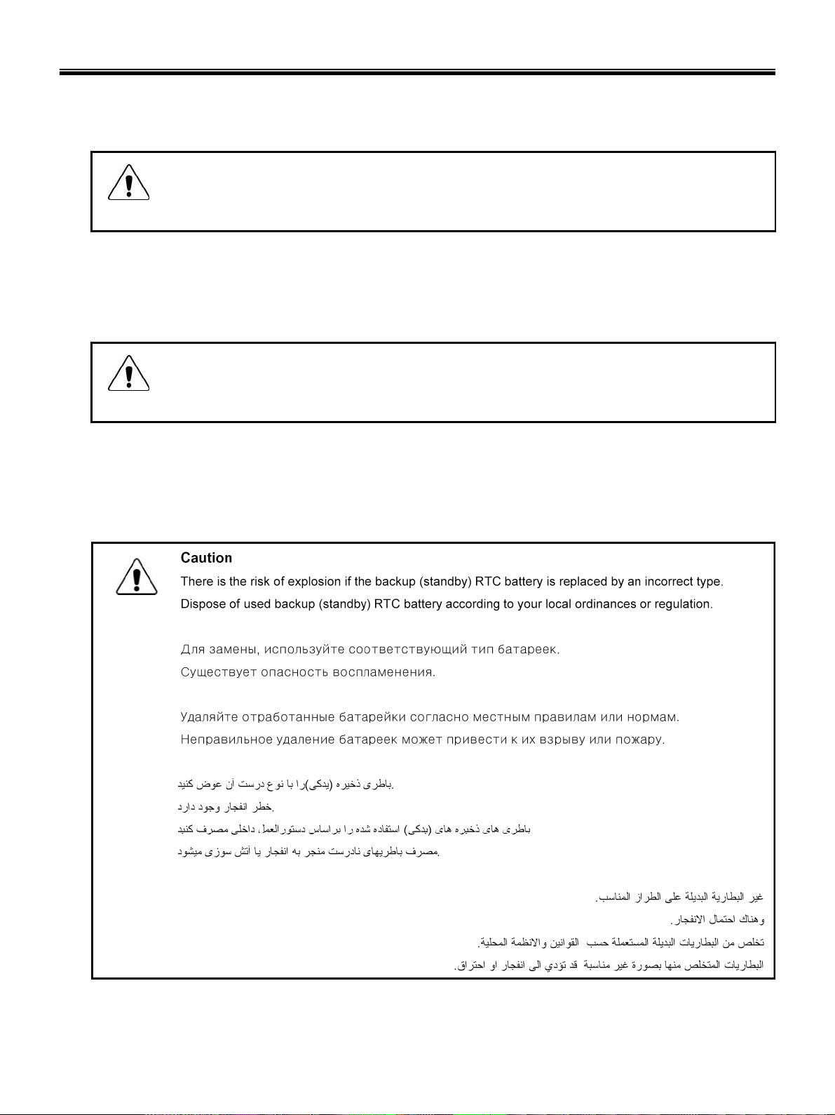
1-5. Backup (Standby) RTC battery safety information
When replacing or disposing of the backup (standby) RTC battery, note the following :
9
Page 12

Ch1. Service information
1-6. Read this first
Before you go to the checkout guide, be sure to read this section.
Important Notes
· Only trained personnel certified by LG should service the computer.
· Read the entire FRU removal and replacement page before replacing any FRU.
· Use new nylon-coated screws when you replace FRUs.
· Be extremely careful during such write operations as copying, saving, formatting.
Drives in the computer that you are servicing sequence might have been altered. If you selected an
incorrect drive, data or programs might be overwritten.
· Replace FRUs only for the correct mode.
· When you replace a FRU, make sure the model of the machine and the FRU part number are correct by
referring to the FRU parts list.
· A FRU should not be replaced because of a single, irreproducible failure. Single failures can occur for a
variety of reasons that have nothing to do with a hard ware defect, such as cosmic radiation,
electrostatic discharge, or software errors.
· Consider replacing a FRU only when a problem recurs. If you suspect that a FRU is defective, clear the
error log and run the test again. If the error does not recur, do not replace the FRU.
· Be careful not to replace a non-defective FRU.
What to do first
You must fill out the record form first.
During the warranty period, the customer may be responsible for repair costs if the computer damage was
caused by misuse, accident, modification, unsuitable physical or operating environment, or improper
maintenance by the customer. The following list provides some common items that are not covered under
warranty and some symptoms that might indicate that the system was subjected to stress beyond normal
use. Before checking problems with computer, determine whether the damage is covered under the
warranty by referring to the following :
10
Page 13

Ch1. Service information
The followings are not covered under warranty :
· CD panel cracked from the application of excessive force or from being dropped
· Scratched (cosmetic) parts
· Distortion, deformation, or discoloration of the cosmetic parts
· Cracked or broken plastic parts, broken latches, broken pins, or broken connectors caused by excessive
force
· Damage caused by liquid spilled into system
· Damage caused by improper insertion of a PC Card or the installation of an incompatible card
· Damage caused foreign material in the diskette drive
· Diskette drive damage caused by pressure on the diskette drive cover or by the insertion of a diskette
with multiple labels
· Damaged or bent diskette eject button
· Fusses blown by attachment of a non-supported device
· Forgotten computer password (making the computer unusable)
· Sticky keys caused by spilling a liquid onto the keyboard
The following symptoms might indicate damage caused by non-warranted activities :
· Missing parts might be a symptom of unauthorized service or modification.
· If the spindle of a hard-disk drive becomes noisy, it may have been subjected to excessive force, or
dropped.
11
Page 14
Chapter 2. Locations
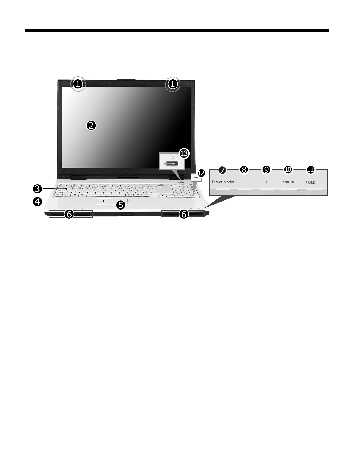
Front view – S1
Ch2. Locations
1. Wireless LAN/Bluetooth antenna
※ Bluetooth equipemtn is optional in sales.
2. LCD Monitor
3. Keyboard
4. Touch pad
5. Touch pad button
6. Built-in Speakers
7. Direct Media Button
- Click Direct Media button to start media program selected from control panel. LG Direct Media function is
available while the system is off, in standby mode, or in hibernation mode. (Power DVD is set to factory
default settings.)
8. Volume down button
9. Volume up button
10. SRS Button
- SRS is not performed by default and press SRS button to use this funtion and set SRS WOWXT / SRS
TrueSurroundXT. SRS TruSurroundXT generates 5.1 Channel digital surround sound from 2 channels of
sound and SRS WOWXT give field effect to 2 channels of sound.
12
Page 15
Ch2. Locations
11. HOLD button
- You can lock the Direct Media button, volume up/down button, and SRS button on the front side by
pushing hold button. Unlock to use buttons in the front side.
12. Authentic Fingerprint Device
※ Authentic Fingerprint device is optional in sales.
13. Built-in Microphone
14. Power button
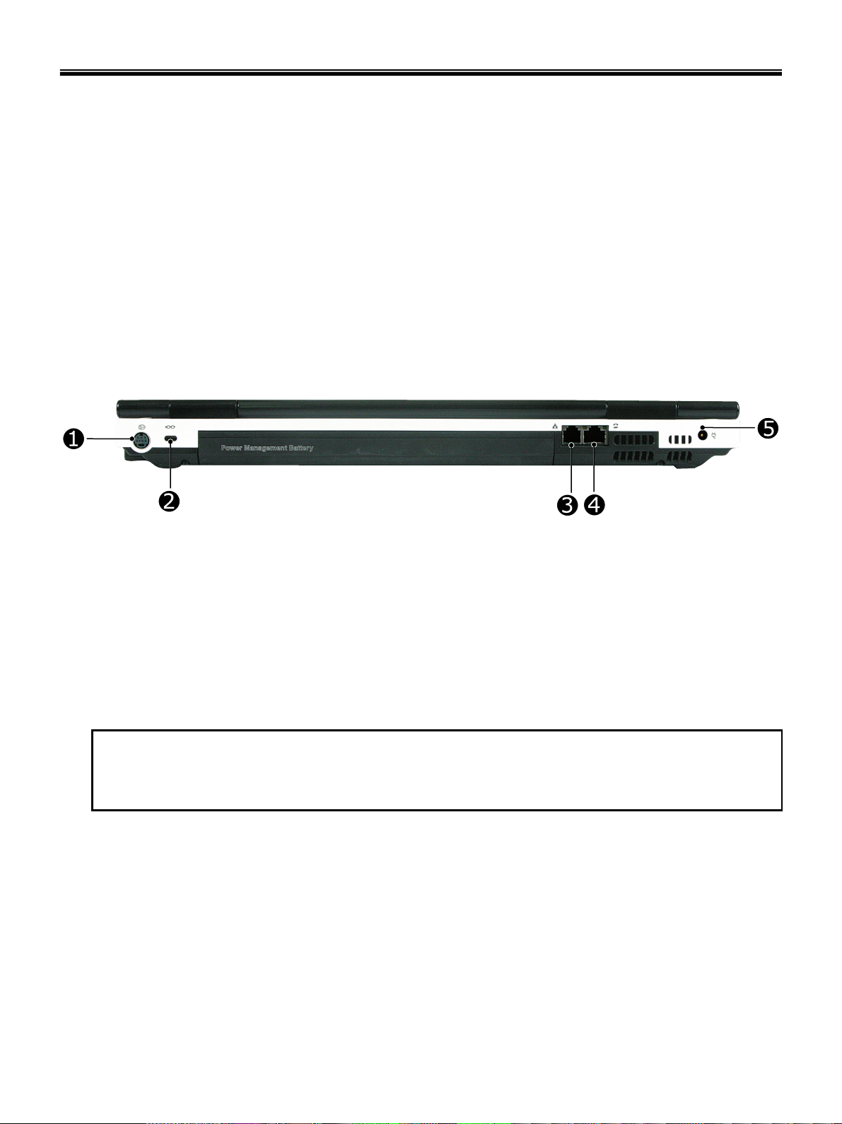
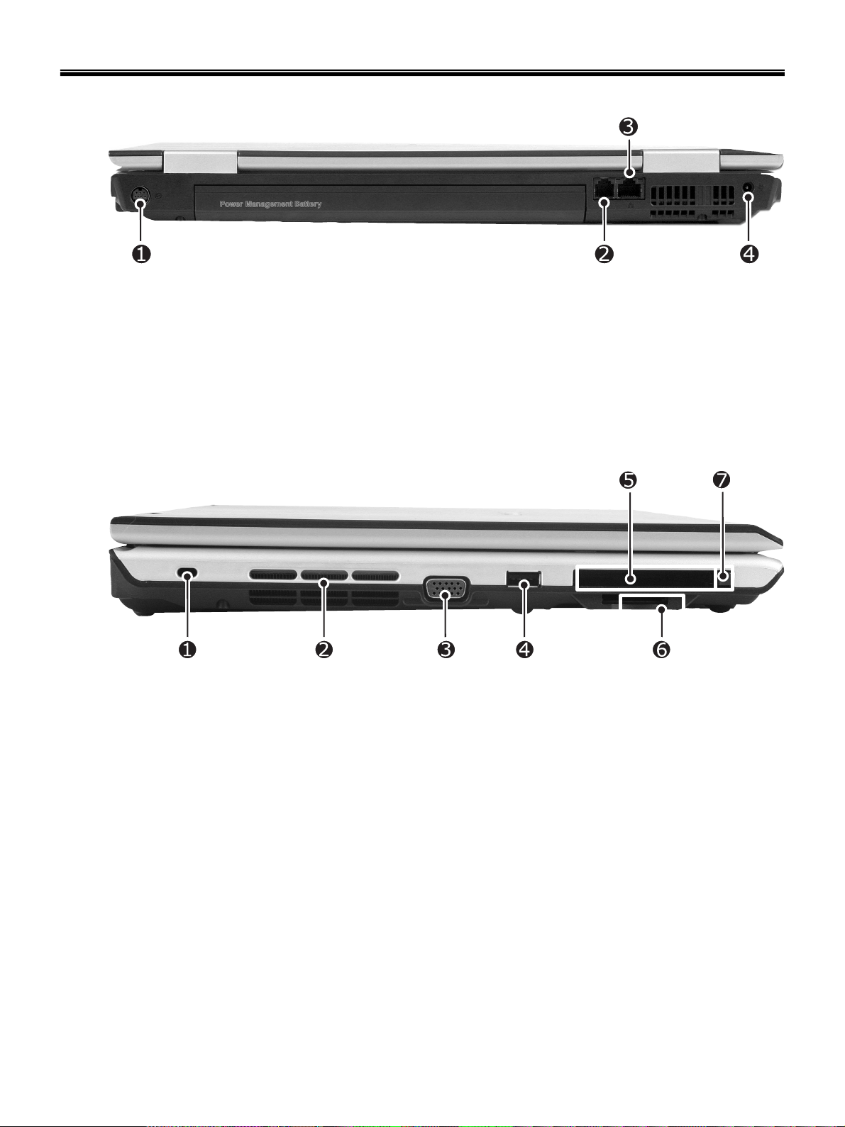
Rear view – S1
1. S-Video Connector
※ It is compatible with 4pin S-Video Cable.
2. Security keyhole
3. Modem connector
※ Specifications may be different depending on the model.
4. LAN Connector
5. Power connector
※ Security Keyhole
User can attach a separately purchased chain lock into the security keyhole and connect it to a fixed object
to prevent a notebook theft.
13
Page 16
Ch2. Locations
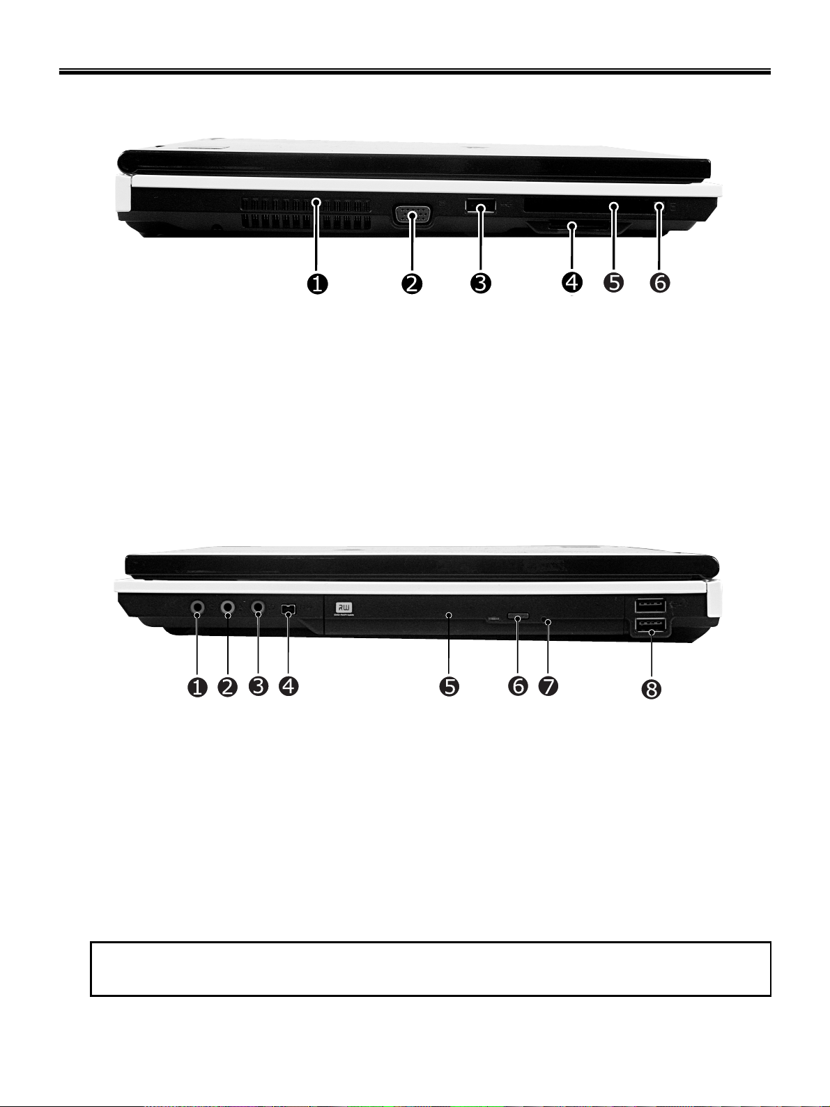
Left view – S1
1. Fan louvers
2. VGA Connector
3. USB Connector
4. Using 5-in-1 (XD / SD / MMC / Memory Stick / Memory Stick Pro) Card
5. Express/PCMCIA Card slot
※ Specifications may be different depending on the model.
6. PCMCIA Card eject button
Right view – S1s
1. Microphone connector
2. Headphone connector
3. Line-in / S/PDIF Connector
4. IEEE 1394 Connector
5. Optical Disk Drive
6. Disk tray button
7. Emergency eject hole
8. USB Connector
※ Emergency eject hole
Insert a thin and hard pin into this hole, and you can open the disc tray manually.
14
Page 17
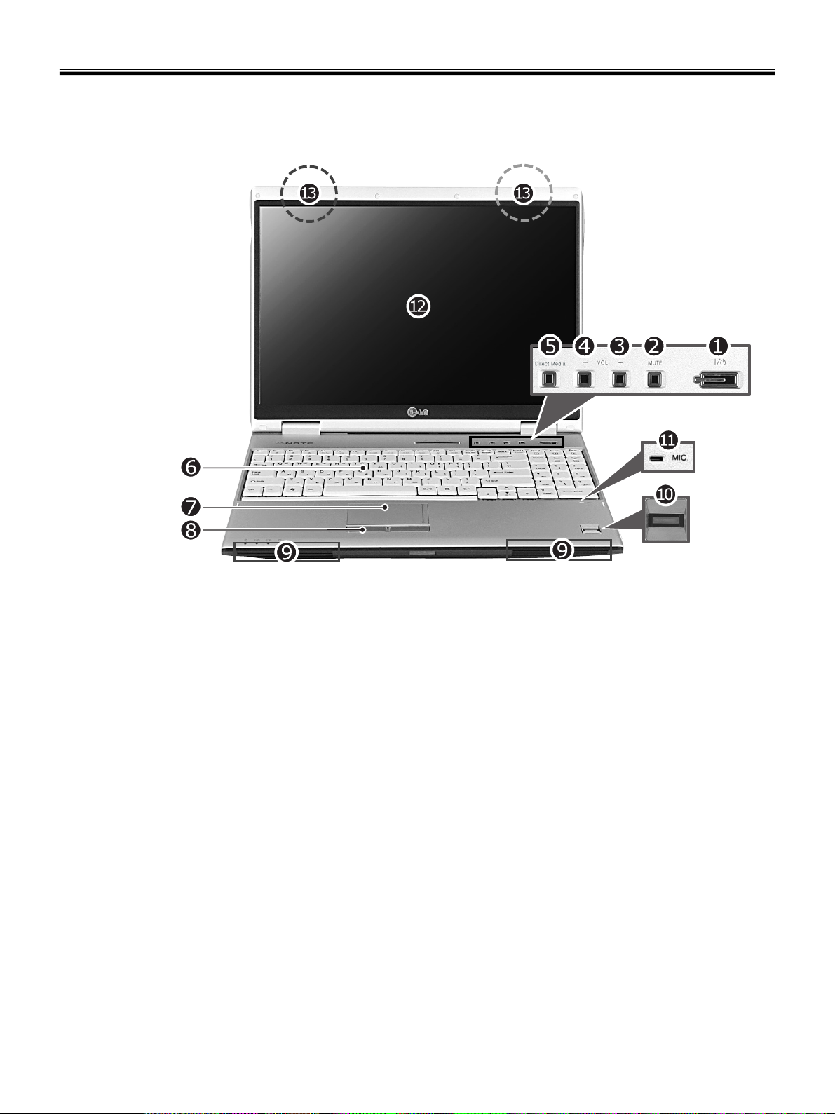
Front view – P1
Ch2. Locations
1. Power button
2. SRS Button
3. Volume up button
4. Volume down button
5. Direct Media Button
6. Keyboard
7. Touch pad
8. Touch pad button
9. Built-in Speakers
10. Authentic Fingerprint scanner
※ Authentic Fingerprint device is optional.
11. Built-in Microphone
12. LCD Monitor
13. Wireless LAN
※ Mini Express Wireless LAN Card is optional.
15
Page 18
Ch2. Locations
Rear view – P1
1. S-Video Connector
※ It is compatible with 4pin S-Video Cable.
2. Modem connector
※ Specifications may be different depending on the model.
3. LAN Connector
4. Power connector
Left view – P1
1. Security keyhole
2. Fan louvers
3. VGA Connector
4. USB Connector
5. Express/PCMCIA Card slot
※ Specifications may be different depending on the model.
6. 5-in-1 Card slot (XD/SD/MMC/Memory stick/Memory stick Pro)
7. PCMCIA Card eject button
16
Page 19
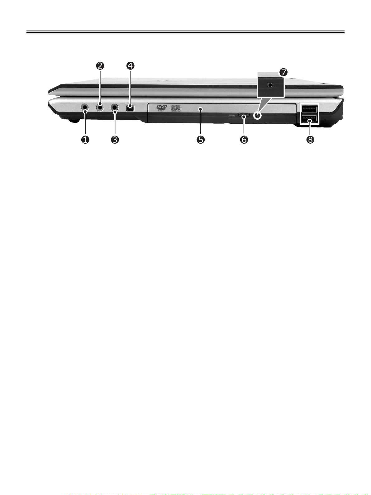
Right view – P1
1. Microphone connector
2. Headphone connector
3. Line-in / S/PDIF Connector
4. IEEE 1394 Connector
5. Optical Disk Drive
Ch2. Locations
6. Disk tray button
7. Emergency eject hole
8. USB Connector
17
Page 20

Ch3. System information
Chapter 3. System information
Specification – S1 / P1
-CPU
· Yonah 1.66 ~ 2.16 GHz
· μFCPGA
- Main Chipset & Graphic
· Intel 945GM,ICH7-M
· Intel 945PM, ICH7-M, ATI Mobility Radeon X1300/X1400/X1600 VGA Controller
- Memory
· 2SODIMM – Up to 2GB
· DDR2 PC2-5300S Capable (667MHz)
- HDD
· 2.5” 9.5mm 60/80/100/120GB PATA Type
· 2.5” 9.5mm 60/80/100GB SATA Type
- Communication
· Modem, Daughter Card Type
· Bluetooth, Daughter Card Type
· Agere Systems PCI-E Gigabit Ethernet Controller on Board
- Wireless LAN Solution
· 802.11 abg PCI-express Mini Card Type, Hexa-band Antenna
-Security
· Trust Platform Module (TPM 1.2)
· Authentec EntréPad 2501A Fingerprint Sensor
- Card Slot
· PCMCIA Card Slot
· 5-in-I Card Slot (Memory Stick/ Pro, Multi Media Card, SD Card, xD-Picture Card)
-ODD
· Fixed Optical Storage
· DVD-COMBO / Super-Multi
-Port
· VGA, 3X USB(2.0), RJ11, RJ45, Headphone, SPDIF, Line-in, AC-in, IEEE1394, S-Video
- Input Devices
· Keyboard : 99Key Keyboard
· Touchpad
- Buttons
· Power, Volume Down, Volume Up, SRS, Q-Play
- Indicator (LED)
· AC-in, Power On, Charge, HDD, Caps Lock, Num Lock, Wireless/Bluetooth
- Power
· 90 Watt 19V 4.74A Adapter
-Audio
· Realtek Azalia Audio Codec, Stereo speakers each 1.5/1.5W
-Battery
· 6 Cell 5.2AHr, CYLINDRICAL (Li-Ion)
· 9 Cell 7.8AHr, CYLINDRICAL (Li-Ion)
18
Page 21
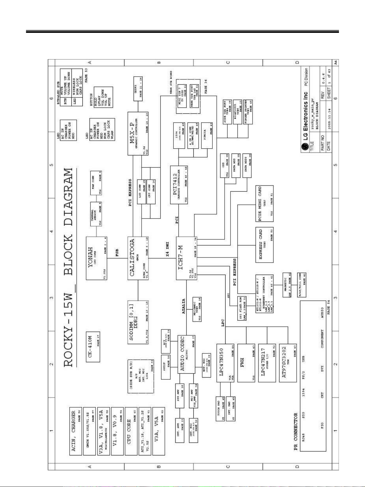
System Block Diagram
Ch3. System information
19
Page 22

Ch3. System information
Fn key combinations
The following table shows the function of each combination of Fn with a function key.
Function of Fn keys has nothing to do with Operating System.
User defined Hot key. (Setting is available at OSD) [Fn]+[F1]
User defined Hot key. (Setting is available at OSD) [Fn]+[F2]
User defined Hot key. (Setting is available at OSD) [Fn]+[F3]
Force the computer to enter power-saving mode. (ex: system standby or hibernation) [Fn]+[F4]
Press the combination keys each time for Touchpad Enable / Touchpad Disable /
Touchpad Auto-dasable.
[Fn]+[F5]
In Touchpad Auto-disable mode, Touchpad is disabled while USB or PS2 mouse is
connected.
Press again to change touchpad modes.
[Fn]+[F6]
[Fn]+[F7]
[Fn]+[Num Lk]
Wireless LAN, Bluetooth On/Off.
Setting is available at OSD. The default is set to Wireless LAN, Bluetooth On/Off.
Monitor toggle. When the computer is attached to an external monitor, you can
change the display output location with [Fn] + [F7] combination.
Power scheme change (Refer to the Battery Miser) [Fn]+[F8]
Mute(Sound On / Off) [Fn]+[F9]
Shows System information [Fn]+[F10]
Fan control function CPU Cooling Fan control mode (Normal / Slow/ Fast) [Fn]+[F11]
Maximum power-saving mode (When OSD is installed). [Fn]+[F12]
Keys with square mark are enabled.
“.Del” key functions as an Insert key while Num Lock is off.
Brighten the LCD Nine steps are available. [Fn]+[▲]
Darken the LCD Nine steps are available. [Fn]+[▼]
20
Page 23
Ch3. System information
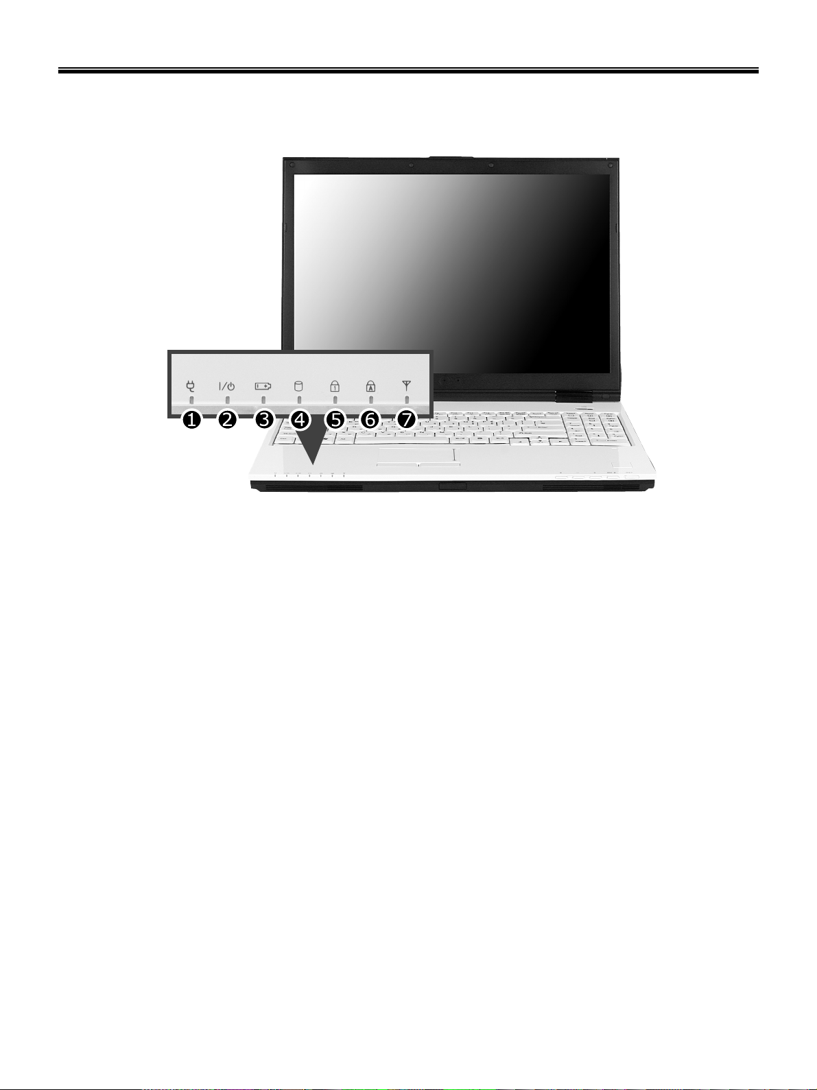
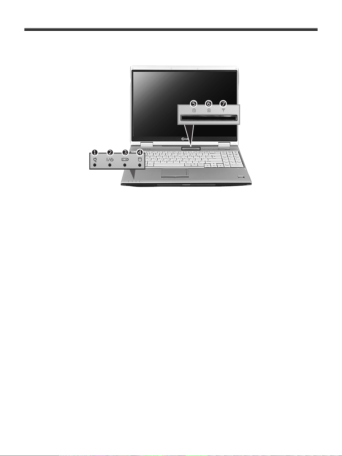
Status indicators – S1
The system status indicators show the status of the computer
1. AC adapter indicator
2. Power indicator
- Power indicator lights up when the power cord is connected to the computer.
- OFF : Power is off, or it is entered system hibernation mode
- Orange : Notebook PC is turned on
- Blinking: Stand by mode
3. Battery status indicator: Charging the battery
- Battery status indicator indicates the computer is connected to an AC adaptor and is being charged.
Indicator is off when the battery is fully charged OR the computer is not connected to an AC Adapter.
- When the battery is being charged (with AC adapter connected to the computer): On
- When the battery is fully charged: OFF
- When the computer is not connected to an AC Adapter: OFF
- When the battery power is under 10% of its maximum capacity: Blinking
- The battery is defective: Blinking
※ The Battery indicator blinks as you have set the alarm action from the Battery miser 2005.
4. Hard disk drive indicator
- Indicator lights up when the Notebook PC access to the hard disk drive.
※ Do not turn off the computer when the drive indicator lights up. It may cause data loss to the computer.
21
Page 24

Ch3. System information
5. Num Lock Indicator
- You can press the [Num Lk] key to enable the embedded numeric keypad. Press the [Num Lk] keys again to
enable the Home/End/PaUp/PgDn/direction key of keypad.
6. Caps Lock Indicator
- Caps Lock indicator lights up when Caps Lock key is pressed. When this indicator lights up, you can type
capital letters without pressing the Shift key.
7. Wireless LAN/Bluetooth indicator
※ Wireless LAN/Bluetooth Indicator may differently lights up depending on the model.
※ Bluetooth equipment is optional in sales.
- OFF : Wireless LAN/Bluetooth is not in use.
- Blinking: Wireless LAN/Bluetooth is connected.
- Blinking(2 to 3 seconds): Wireless LAN/Bluetooth is not connected while Wireless Radio is on.
- Blinking(3 to 4 seconds): Searching for the Access point to connect Wireless LAN/Bluetooth.
- ON : Connected or finding a connection to the access point.
22
Page 25
Ch3. System information
Status indicators – P1
The system status indicators show the status of the computer
1. AC adapter indicator
2. Power indicator
- Power indicator lights up when the power cord is connected to the computer.
- OFF : Power is off, or it is entered system hibernation mode
- Green : Notebook PC is turned on
- Blinking: Stand by mode
3. Battery status indicator: Charging the battery
- Battery status indicator indicates the computer is connected to an AC adaptor and is being charged. Indicator is off
when the battery is fully charged OR the computer is not connected to an AC Adapter.
- When the battery is being charged (with AC adapter connected to the computer): ON
- When the battery is fully charged: OFF
- When the computer is not connected to an AC Adapter: OFF
- When the battery power is under 10% of its maximum capacity: Blinking
- The battery is defective Blinking
※ The Battery indicator blinks as you have set the alarm action from the Battery miser 2005.
4. Hard disk drive indicator
- Indicator lights up when the Notebook PC access to the hard disk drive.
※ Do not turn off the computer when the drive indicator lights up. It may cause data loss to the computer.
5. Num Lock Indicator
- You can press the combination of [Fn] and [ScrLk] keys to enable the embedded numeric keypad. Press the
combination of [Fn] and [ScrLk] keys again to disable the embedded numeric keypad.
6. Caps Lock Indicator
- Caps Lock indicator lights up when Caps Lock key is pressed. When this indicator lights up, you can type capital
letters without pressing the Shift key.
23
Page 26

Ch3. System information
7. Wireless LAN Indicator
※ Wireless LAN Indicator may differently lights up depending on the model.
- OFF : Wireless LAN is not in use.
- Blinking: Wireless LAN is connected.
- Blinking(2 to 3 seconds): Wireless LAN is not connected while Wireless Radio is on.
- Blinking(3 to 4 seconds): Searching for the Access point to connect Wireless LAN.
- ON : Connected to Access point.
24
Page 27

Ch3. System information
BIOS Flash
You can update BIOS using a floppy disk drive.
Because this system is not equipped with any floppy disk drive, you have to use an external USB drive for
a BIOS update. In order to boot up with an USB drive, please set Removable Device as the first boot up
drive in the boot menu of BIOS setup.
· How to update flash ROM in DOS
1. Create ‘boot up’ flash update diskette.
2. Copy a ROM image file (*.wph) into the root of the flash update diskette.
3. Copy phlash16.exe to the flash update diskette.
4. Insert the diskette into the FDD of your computer.
5. Boot your computer with the diskette, and type ‘phlash16*.wph /mode=n’.
6. Cold boot and follow the instruction displayed on the screen.
· Flash options /mode=n
0 – Default mode. Keep the current DMI information and update BIOS image only.
1 – Update DMI information only.
If new DMI information is not specified, the current DMI information is left unchanged.
2 – Update BIOS and DMI information.
If new DMI information is not specified, the current DMI information is left unchanged.
3 – Update BIOS and DMI information.
DMI information is updated to the DMI string and options specified in the new BIOS image.
Note
DMI is Desktop Management Interface
25
Page 28
Ch3. System information
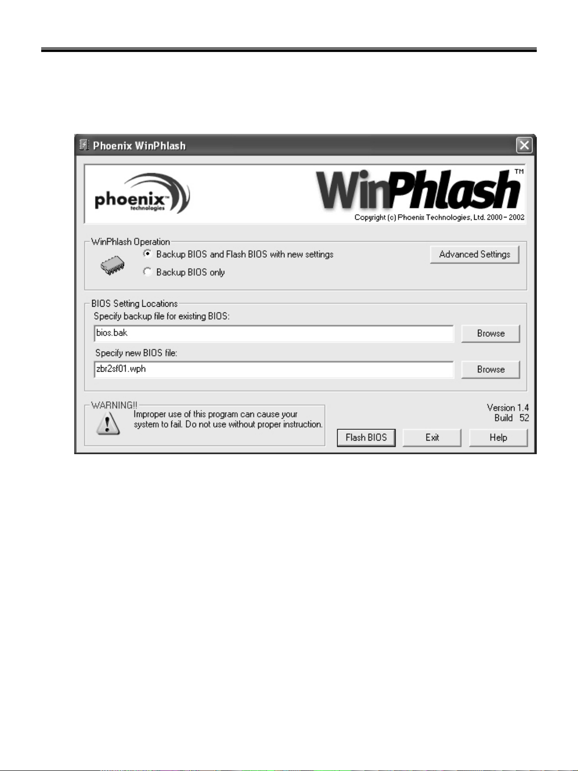
How to update flash ROM in Windows
1. Quit all running programs.
2. Start WINPHLASH.EXE.
3. Select the procedure you want :
a. Backup BIOS and Flash BIOS with new settings
b. Backup BIOS Only
4. Specify the locations for backup and new BIOS files in BIOS Setting Locations.
a. Enter the name of the backup file for existing BIOS or click Browse to locate the file.
b. Enter the name of the new BIOS file or click Browse to locate the file.
5. Click Advanced Settings button to access the advanced settings
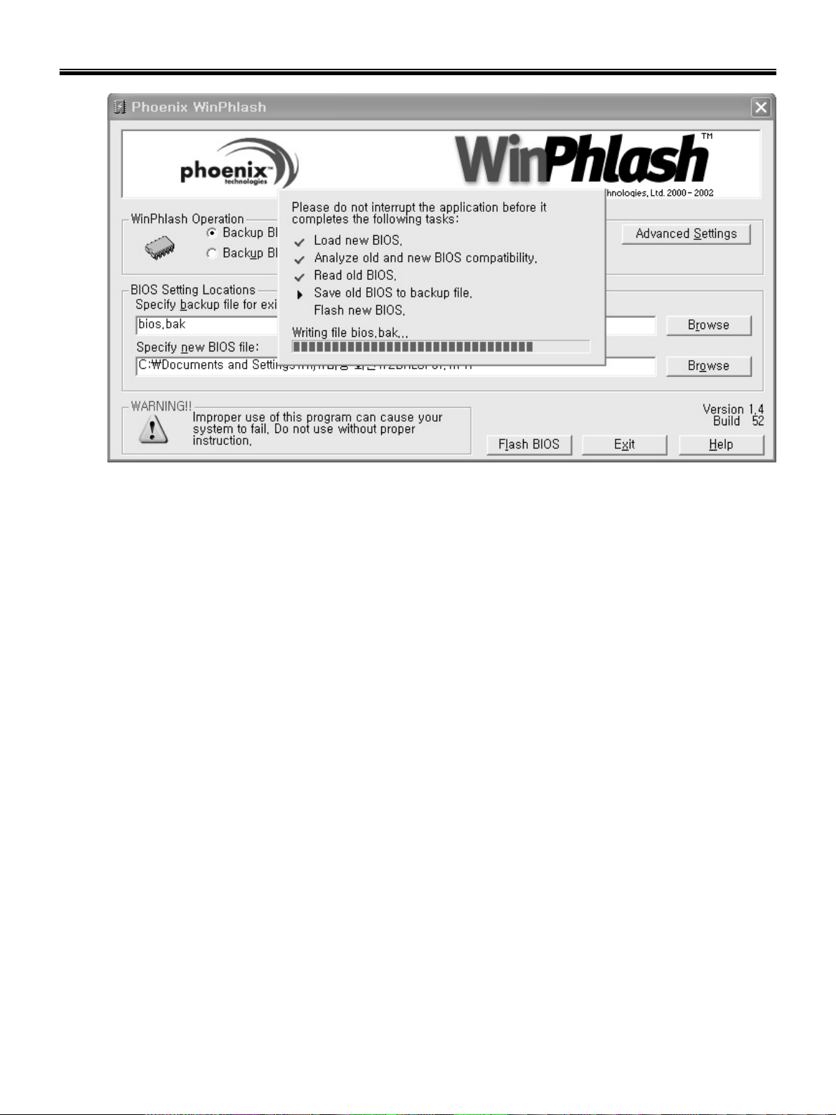
6. Click Flash BIOS button to start flash BIOS.
7. Wait for the operation to complete. WinPhlash may take one or two minutes to complete flash BIOS
operation.
26
Page 29
Ch3. System information
8. After the completion, ‘System BIOS was successfully updated’ appears on the screen, then the
computer restarts.
9. After the restart, make sure the system BIOS is updated.
10. If your computer does not restart automatically, turn off your computer and then turn it back on by
pressing power button.
27
Page 30
Ch3. System information
BIOS Release Process and Making Bootable CD
1. LGE(Korea) will send BIOS Image (*.iso) to each Service Centers when we have a new revision.
(Please refer to the BIOS Table (Document No. SBE-HA-01) for latest BIOS)
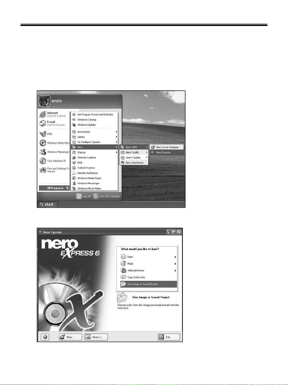
2. Service center will make Bootable Image CD with Image file(*.iso) as below
a. Insert empty disc to CD-RW Drive and start Nero Burning ROM.
b. Select Disc Image or Saved Project.
28
Page 31

Ch3. System information
c. Select File Format as "Image Files(*.iso)".
d. Open Image File(*.iso) which is sent from LGE
29
Page 32

Ch3. System information
e. Tab Next then burning will be started
f. Burn process completed as below, and tab “OK”
30
Page 33

Ch3. System information
BIOS/EC Flash Process
1. Insert Bootable CD in PC, and Turn it on, then PC will boot by DOS mode as below
(If the EC is not correct or old version, then automatically update EC first and reboot again)
2. Type in Mode Name at the “WIP ID :” then press Enter key (You must use Capital Letter)
(You can see the Model Name in ID Label at the bottom Case of PC: “M/N: LMXX-XXXX”)
3. Type in Serial No at the “WIP ID :” then press Enter key (You must use Capital Letter)
(You can see the Serial No in ID Label at the bottom Case of PC: “S/N: 412KIXXXXXXXX”(13digits))
31
Page 34

Ch3. System information
4. You can see the BIOS flash process as below
5. After flashing is completed, you can see the “PASS” on your screen, and reboot your PC
32
Page 35

Ch3. System information
BIOS Setup
BIOS (Basic Input and Output System) Setup saves the system configuration in CMOS RAM, and
check the configurations during startup. Use the BIOS Setup Utility to change and save the system
environment, hardware configurations, power saving mode, etc.
· Open the BIOS Setup Utility in the following situations :
1. to change the BIOS setup
2. to replace the backup battery
3. system configuration error occurs
4. to change the boot order
5. to set/change a password
Press the power button.
When the LG logo appears on the screen, press and enter the BIOS Setup Utility.
33
Page 36

Ch3. System information
Using the keys
The keys used in the BIOS Setup Utility and their functions are described at the bottom.
· , + : General Help
Display the descriptions of the keys used in the setup utility.
· , : Select Item
Navigate and select items in the setup utility. The selected item becomes highlighted.
· , : Select Menu
Move to another menu.
· / , : Change Values
Change the value of a selected item.
· : Load Default Configuration
Display Setup Confirmation window. Press Enter to load default configuration.
· : Select Sub-Menu
Some items have sub-menus. Display the sub-menu for a selected item.
· : Save and Exit
Display Setup Confirmation window. Press Enter to save and exit.
·: Exit
In a sub-menu, press Esc to move to the previous window. In Main menu, click Esc to move to Exit menu.
34
Page 37

Ch3. System information
Main menu
System Time
Current time. Use <Tab>, <Shift-Tab>, or <Enter> keys to move around these fields. To change the
value, press <+> or <−> key.
System Date
Today date. Use <Tab>, <Shift-Tab>, or <Enter> keys to move around these fields. To change the value,
press <+> or <−> key. Set any date from year 1981 to 2079. It will automatically keep track of leap years.
The system date can also be set from the operating system.
Product Name
This shows the name of PC.
Processor Type
This shows the type of CPU.
Processor Spd
This shows the speed CPU.
BIOS Version
This shows the Version of BIOS.
KBC Version
This shows the Version of KBD firm ware.
UUID
This is for display only. This shows the UUID.
Pri Master
Enter its submenu by pressing <Enter>. In this submenu, it would show the device of Primary IDE Master
is HDD and its parameters.
Sec Slave
Enter its submenu by pressing <Enter>. In this submenu, it would show the device of Secondary IDE
Slave is optical drive and its parameters.
Total Memory
This is for display only. This shows size of system memory.
35
Page 38

Ch3. System information
Advanced menu
Legacy USB Support
There are two options to this field: Enabled, and Disabled. This field allows you to enable or disable the
legacy USB support.
Boot-time Diagnostic Screen
Enables the Boot-time Diagnostic Screen.
Core Multi-Processing
Enables the Dual-Core technology.
Boot-time Diagnostic Screen
Enables the Boot-time Diagnostic Screen.
SATA Controller Mode
Set SATA (Serial ATA) Controller Mode.
AHCI Configuration
Enables the AHCI (Advanced Host Controller Interface).
Battery Charge Stop Percentage
Set Battery Charge Stop Percentage.
Fan Mode Control
Set Fan Mode Control.
Fn Key Setup
Set Sticky fn key function.
Wake On Lan
Enables Wake On Lan.
PCIE Device Wake Up
Enables Wake On PCIE device.
PXE/Remote Boot OPROM
Enables PXE/Remote Boot.
MEF Support
Control the MEF device in an ACPI environment.
SIO Control Sub-Menu
Control the configuration of various National 393 SIO devices.
36
Page 39

Ch3. System information
Security menu
Supervisor Password Is
This shows the system’s supervisor password has been set, or not.
Set Supervisor Password
Set Supervisor Password.
User Password Is
This shows the system’s User Password has been set, or not.
Set User Password
Set User Password.
Password on boot
Enables Password on boot.
HDD Password Is
This shows the system’s HDD Password has been set, or not.
Set HDD Password
Set HDD Password.
Boot menu
Boot menu enables you to set the boot order for the CD-ROM drive, Removable devices Hard drive, and
Network boot as shown below.
Boot Priority order / Excluded from boot order
Up and Down arrows select a device. <+> and <-> moves the device up or down. <f> and <r> specifies
the device fixed or removable.
<x> exclude or include the device to boot.
<Shift + 1> enables or disables a device.
<1 – 4> Loads default boot sequence.
37
Page 40

Ch3. System information
Boot menu
Exit Saving Changes
Select Exit Saving Changes to save new setup information in CMOS RAM. CMOS RAM stores the
information using the backup battery; therefore, the information will not be lost when the computer is
turned off.
Exit Discarding Changes
Select Exit Discarding Changes to discard new setup information. If you made changes to items other
than date, time, and passwords, the Setup Warning asks you to save the new configurations. Select Yes
and press Enter to save the new configuration.
Load Setup Defaults
Select Load Setup Defaults to change the setup information to the factory default settings. If you select
Load Setup Defaults or press F9, Setup Confirmation asks you to confirm your selection. Press Yes to
load setup defaults.
Discard Changes
Discard change value.
Save Changes
Save change value.
38
Page 41

Ch3. System information
■ Backup and Restore Security Platform Data
Security Platform Backup includes all data required in case of emergency. After a hardware or storage
media failure or a Trusted Platform Module failure, Security Platform Restoration reestablishes access to
Security Platform Features for all users.
In addition you can backup and restore your Personal Secure Drive data. Data from other applications
using the Security Platform Solution (e.g. Secure e-mail) is not included in Security Platform backup.
■ Backup scope
Security Platform backup comprises the following data:
Security Platform Credentials and Settings
Backup Contents
Purpose
Archives
Emergency Recovery
Backup Contents
Purpose
A copy of the user-specific credentials and settings which are stored on the
Security Platform.
Restoration of user-specific credentials and settings after a hardware or
storage media failure.
Otherwise users could not access Security Platform Features anymore
and user data would be lost.
•
Automatically written Backup Archive ("System Backup Archive",
e.g. file
Security Platform Administrator. Contains credentials and settings of all
Security Platform Users (for one or multiple Security Platform
computers). Also contains computer identification and user
identification, which are used to match computers and users during the
restoration process.
•
Manually written Backup Archive (e.g.
Created by Security Platform User. Contains credentials and settings of
one Security Platform User (for one Security Platform computer). Also
contains computer identification and user identification, which are used
to match computer and user during the restoration process.
All Security Platform Basic User Keys, encrypted specifically for Emergency
Recovery.
Re-encryption of all Basic User Keys after a Trusted Platform Module failure.
In this case a new Security Platform has to be set up and a new owner
key is created. Emergency Recovery allows the re-encryption of Basic
User Keys from the old owner key to the new one.
Otherwise users could not access Security Platform Features anymore
and user data would be lost.
SPSystemBackup.xml
and folder
SPSystemBackup
SPBackupArchive.xml
): Set up by
):
Archives
•
Emergency Recovery data is included in automatically written
Backup Archives.
•
Emergency Recovery Token (e.g.
Security Platform Administrator. Protected with a dedicated password.
Is required for a restoration of Emergency Recovery data.
SPEmRecToken.xml
): Created by
39
Page 42

Personal Secure Drive
Ch3. System information
A copy of the PSD encrypted data and configuration settings.Backup Contents
Purpose
Archives
Restoration of PSD encrypted data and configuration settings after a
hardware or storage media failure.
Otherwise users could not decrypt their PSD data anymore.
Notes:
•
In contrast to the PSD Backup, standard hard disk backup tools
produce unencrypted backups.
•
Lost PSD credentials can only be restored via Personal Secure Drive
Recovery.
•
PSD configuration settings are included in both automatically
written Backup Archives and manually written Backup Archives.
•
PSD backup file (e.g.
image file may be created during a Security Platform User's manual
backup.
SpPSDBackup.fsb
■ Restoration Cases
Depending on the type of emergency there are different restoration cases
Affected Restoration ScopeRestoration Case
Broken hard disk or lost data
Security Platform Credentials and Settings, Personal
Secure Drive
Emergency RecoveryNew Trusted Platform Module
): A backup copy of the PSD
New Security Platform to be initialized
Emergency Recovery, Security Platform Credentials
and Settings, Personal Secure Drive
40
Page 43

Ch3. System information
■ How to Backup and Restore
("System Backup")
Software Component to useHow to configure automatic backups
Administrative Task: Configure automatic
backups for all users (including Security
Platform Credentials and Settings,
Emergency Recovery and PSD configuration
settings).
current user.
certain users.
User Task: Run restoration manually for
current user. If restoration has been
prepared for current user, then complete the
restoration.
If a manually written Backup Archive is
available and no Emergency Recovery data
needs to be restored, then a user can
perform restoration without preparation by
an administrator.
■ Backup
If Security Platform is not yet initialized:
Initialization Wizard
If Security Platform is already initialized: Settings
Tool -Backup -Configure...
Software Component to useHow to backup ("Manual Backup")
Settings Tool - Backup - Backup...User Task: Run backup manually for the
Software Component to useHow to restore
Settings Tool - Backup - Restore...Administrative Task: Prepare restoration for
With this page you can configure automatic Security Platform backups.
The following table gives hints on how to use this wizard page.
ExplanationWizard Page Element
Backup location:
Browse...
Schedule...
Security Platform credentials and settings will be regularly saved to a
Backup Archive.
Type in path and file name or browse for it. An automatically written
Backup Archive consisting of an XML file and a folder with the same name
will be created, e.g. file
Please use the extension *.xml.
A scheduled backup will be created.
Click here to view and modify the backup scheduling.
Please note that automatic backups are only executed if your PC is not
shut down at the scheduled time.
Please note that the user account chosen for the scheduled backup must
be member of the group "Administrators" or "Backup Operators".
SPSystemBackup.xml
and folder
SPSystemBackup
.
41
Page 44

Ch3. System information
■ Infineon Platform Security Backup
With this page you can backup and restore Security Platform credentials, Security Platform settings and
Personal Secure Drives.
If Enhanced Authentication is enabled, you can also create backups of your authentication device.
Availability of page: This page is only available on an initialized Security Platform, if one of
the following conditions is fulfilled:
•
The current user has administrative rights.
•
The current user is an initialized Security Platform User, and the policy Allow User Enrollment
is enabled.
Buttons:
•
Buttons for administrative tasks are disabled for users without administrative rights.
•
Buttons are disabled, if corresponding functions are not available in a certain Security Platform
state.
The following table describes all backup and restore functions.
Explanation
Click here to set up automatic Security Platform backups.
Infineon Security Platform Initialization Wizard will be started.
This feature is only available, if the current user account has administrative rights.
Click here to start a manual backup of your Security Platform Settings and credentials. If you have
configured Personal Secure Drive (PSD), you can backup your PSD too.
The Infineon Security Platform Backup Wizard will be started.
This button is disabled, if the Infineon Security Platform is disabled, not yet set up or the user is not
set up.
Click here to start a manual restore of archived Security Platform Settings and credentials. If you
have a backup of your Personal Secure Drive (PSD), you can restore your PSD too.
The restore part of the Infineon Security Platform Backup Wizard will be started.
This button is disabled, if the Infineon Security Platform is disabled or not yet set up.
Click here to create a backup authentication device.
This feature is only available, if Enhanced Authentication is enabled.
42
Page 45

Ch4. Symptom-to-part index
Chapter 4. Symptom-to-part index
The symptom-to-part index in this section lists symptoms and errors and their possible causes.
The most likely cause is listed first.
Note
If replacing a part (FRU) does not solve the problem, put the original part back in the computer.
Do not replace a non-defective FRU.
Power system checkout
· To verify a symptom, do the following :
1. Power off the computer.
2. Remove the battery pack.
3. Connect the AC adapter.
4. Check that power is supplied when you power on the computer.
5. Power off the computer.
6. Disconnect the AC adapter and install the charged battery pack.
7. Check that the battery pack supplies power when you power on the computer.
· If you suspect a power problem, see the appropriate one of the following power supply checkouts :
1. Checking the AC adapter
2. Checking the operational charging
3. Checking the battery pack
4. Checking the backup battery
· Checking the AC adapter
If the power-on indicator does not turn on, check the power cord of the AC adapter for correct continuity
and installation.
If the computer does not charge during operation, go to “Checking operational charging.”
43
Page 46

Ch4. Symptom-to-part index
To check the AC adapter, do the following :
1. Unplug the AC adapter cable from the computer.
2. Measure the output voltage at the plug of the
AC adapter cable. See the following figure :
3. If the voltage is not correct, remove the power code
2
1
form AC adapter.
4. 10 seconds later, connect the power code, then measure the output voltage.
5. If the voltage is not correct, change the AC adapter.
Voltage (V dc)Pin
+18.05 ~ +19.951
Ground2
44
Page 47

Ch4. Symptom-to-part index
· If the voltage is not correct, replace the AC adapter.
· If the voltage is acceptable, do the following :
1. Replace the system board.
2. If the problem persists, check the AC adapter whether it is correct product or not.
Note
Noise from the AC adapter does not always indicate a defect.
· Checking operational charging
1. To check whether the battery charges properly during operation, use a discharged battery pack or a
battery pack that has less than 50% of the total power remaining when installed in the computer.
Perform operational charging. If the battery status indicator or icon does not turn on, remove the battery
does not turn on, replace the battery pack.
2. If the charge indicator still does not turn on, replace the system board.
Then reinstall the battery pack.
Note
Do not charge battery pack, when its temperature is below 0 or above 75 .
· Checking the battery pack
1. Open the Power Meter window by clicking Start Control Panel Power Options and then;
check the total power remains. Battery charging does not start until the power Meter shows that less
than 95% of the total power remains; under this condition the battery pack can charge to 100% of its
capacity. This protects the battery pack from being overcharged or from having a shortened life.
2. To check the status of your batter, move your cursor to the Power Meter icon in the icon tray of the
Windows taskbar and wait for a moment (but do not click), and the percentage of battery power
remaining is displayed. To get detailed information about the battery, double-click the Power Meter icon.
Note
If the battery pack becomes hot, it may not be able to charge. Remove it from the computer and
Leave it at room temperature for a while. After it cools down, reinstall and recharge it.
45
Page 48

Ch4. Symptom-to-part index
· The Characteristics of the battery pack
1. Self-discharge
The battery gradually loses its power over time without ever being used.
2. Periodic full discharge / charge
Frequent recharge of the battery pack can reduce the capacity of the battery pack. When this happens,
you can perform the full discharge / charge to improve the capacity. You should perform periodic full
discharge /charge once every 30~60 days.
You should always use the battery until its power is low; then fully charge the battery.
3. Trickle charge
If the temperature of the battery pack drops below 10 , the trickle charging begins.
The trickle charging may take 32 hours for the battery pack to be fully charged.
46
Page 49

Ch4. Symptom-to-part index
· To check the battery pack, do the following :
1. Power off the computer.
2. Remove the battery pack and measure the voltage between battery terminals 1(-) and 5(+).
See the following figure :
Voltage (V dc)Terminal
Ground(-)1
5(+) 4 3 2 1(-)
3. If the voltage is still less than +11.1 V DC after recharging, replace the battery.
4. If the voltage is more than +11.1 V DC, measure the resistance between battery terminals 1 and 2.
The resistance must be 2 to 4 (typically 3 ).
5. If the resistance is not correct, replace the battery pack. If the resistance is correct, replace the system
board.
Note
Charging will take at least 3 hours.
Note
Battery is an expendable supplier, so its capacity and used time can be reduced by using the computer.
5
+0V ~ +12.6V
(6 cell)
47
Page 50

Numeric error codes
Ch4. Symptom-to-part index
FRU or action, in sequenceSymptom / Error
0200
Fixed disk failure
(The hard disk is not working)
0210
Stuck Key error
0211
Keyboard error
Keyboard Controller Failed
Monitor type error - Monitor type does not
match the one specified in CMOS.
1.Reset the hard-disk drive.
2.Load Setup Defaults in BIOS Setup Utility.
3.Hard-disk drive.
4.System board.
1.Check the keyboard if it is pressed.
2.Replace the keyboard.
Run interactive tests of the keyboard and the auxiliary
input device.
System board.0212
Load Setup Defaults in BIOS Setup Utility.0220
0230
System RAM error - System RAM Failed at
offset.
Shadow RAM error - Shadow RAM failed at
offset
0232
Extended RAM error - Extended RAM Failed
at address line
0250
System battery error – System battery is dead
1.DIMM
2.System board
System board0231
1. DIMM
2. System board
Replace the backup battery and run BIOS Setup Utility
to reset the time and date.
48
Page 51

Ch4. Symptom-to-part index
FRU or action, in sequenceSymptom / Error
0251
System CMOS checksum bad
– System CMOS checksum is not correct.
– Default configuration used.
Password checksum bad – The password is
cleared.
0260
System timer error
Check date and time settings – Date and time
error.
0280
Previous boot incomplete
- Default configuration used
from EISA CMOS
Diskette drive A error
Replace the backup battery and run BIOS Setup Utility
to reset the time and date.
Reset the password by running BIOS Setup Utility.0252
1. Replace the backup battery and run BIOS
Setup Utility to reset the time and date.
2. System board.
Run BIOS Setup Utility to reset the time and date.0271
1. Load “Setup Default” in BIOS Setup Utility.
2. DIMM.
3. System board.
Load Setup Defaults in BIOS Setup Utility.0281: Memory Size found by POST differed
Set up the diskette type in BIOS Setup Utility.02B0
Diskette drive B error
02B2
Incorrect drive A type – Floppy diskette drive
error
02B3
Incorrect Drive B type
02D0
System cache error – Cache disabled
(RAM cache failed and BIOS disabled)
02F4
EISA CMOS not writable
02F5
DMA test failed
02F6
Software NMI failed
Set up the diskette type in BIOS Setup Utility.02B1
1. Floppy diskette drive.
2. External FDD cable.
3. I/O card.
1. Floppy diskette drive.
2. External FDD cable.
3. I/O card.
1. Load “Setup Default” in BIOS Setup Utility.
2. System board.
1. Load “Setup Default” in BIOS Setup Utility.
2. Replace the backup battery.
3. System board.
1. DIMM
2. System board
1. DIMM
2. System board
49
Page 52

Ch4. Symptom-to-part index
FRU or action, in sequenceSymptom / Error
02F7
Fail – Safe timer NMI failed
0611
IDE configuration changed
0612
IDE configuration error
0613
Com A configuration changed
0614
Com A configuration error
0615
Com B configuration changed
1. DIMM
2. System board
1. Load Setup Defaults in BIOS Setup Utility.
2. System board.
1. Load Setup Defaults in BIOS Setup Utility.
2. System board.
1. Load Setup Defaults in BIOS Setup Utility.
2. System board.
1. Load Setup Defaults in BIOS Setup Utility.
2. System board.
1. Load Setup Defaults in BIOS Setup Utility.
2. System board.
0616
Com B configuration error
0617
Floppy configuration changed
0618
Floppy configuration error
0619
Parallel port configuration changed
061A
Parallel port configuration error
1. Load Setup Defaults in BIOS Setup Utility.
2. System board.
1. Load Setup Defaults in BIOS Setup Utility.
2. System board.
1. Load Setup Defaults in BIOS Setup Utility.
2. System board.
1. Load Setup Defaults in BIOS Setup Utility.
2. System board.
1. Load Setup Defaults in BIOS Setup Utility.
2. System board.
50
Page 53

Error message
Ch4. Symptom-to-part index
FRU or action, in sequenceSymptom / Error
Device address conflict.
Allocation error for device.
Failing bits: nnnn.
Invalid System Configuration Data.
I/O Device IRQ Conflict.
1. Load Setup Defaults in BIOS Setup Utility.
2. Backup battery.
3. System board.
1. Load Setup Defaults in BIOS Setup Utility.
2. Backup battery.
3. System board.
1. DIMM.
2. System board.
1. DIMM.
2. System board.
1. Load Setup Defaults in BIOS Setup Utility.
2. Backup battery.
3. System board.
Operating System not found.
Hibernation error.
1. Check that the operating system has no failure and
is installed correctly.
2. Enter BIOS Setup Utility and see whether the hard
-disk drive and the diskette drive are properly
identified.
3. Reset the hard-disk drive.
4. Reinstall the operating system.
5. Diskette drive.
6. Hard-disk drive.
7. System board.
1. Restore the system configuration to what it was
before the computer entered hibernation mode.
2. If memory size has been changed, re-create the
hibernation file.
Fan.FAN error.
51
System board.Thermal sensing error.
Page 54

Ch4. Symptom-to-part index
LCD-related symptoms
Note
Before removing or disassembling LCD, power off the computer, unplug all power cords from electrical
outlets, remove the battery pack also.
FRU or action, in sequenceSymptom / Error
Check out Battery Miser.LCD screen becomes dark suddenly.
Nothing displayed on LCD screen.
LCD backlight not working.
LCD too dark.
LCD brightness cannot be adjusted.
LCD color cannot be adjusted.
LCD screen abnormal.
Characters missing pixels.
LCD screen unreadable.
Wrong color displayed.
1. Check out Battery Miser.
2. Choose Never in the Turn off Monitor item on
Power Options Properties.
3. Check the power save mode switch if it is pressed
by something.
4. Check the System is in standby or hibernation
mode.
1. Reconnect inverter to the board connector.
2. Replace inverter.
3. LCD assembly.
4. System board.
1. Reset all LCD connectors.
2. Replace LCD cable.
3. LCD assembly.
4. System board.
on LCD
Power-on indicator on, and a blank\LCD
during POST.
LCD assembly.Horizontal or vertical lines displayed
LCD assembly.
System board.
52
Page 55

Ch4. Symptom-to-part index
Indeterminate problems
· You are here because the diagnostic tests did not identify which adapter or device failed, wrong devices
are installed, a short circuit is suspected, or the system is inoperative.
Follow these procedures to isolate the failing FRU (do not isolate FRUs that have no defects).
· Verify that all attached devices are supported by the computer.
· Verify that the power supply being used at the time of the failure is operating correctly.
1. Power off the computer
2. Visually check each FRU for damage. Replace any damaged FRU.
3. Remove or disconnected all of the following devices :
a. Non-LG devices.
b. Printer, mouse, and other external devices.
c. Battery pack.
d. PC cards.
e. ODD (CD-ROM, Combo) drive or FDD drive in the Bay.
f. Hard-disk drive.
Note
Use the other memory card because it needs when operating computer.
4. Power on the computer.
5. Determine whether the problem has changed.
6. If the problem does not recur, reconnect the removed devices one at a time until you find the failing FRU.
7. If the problem remains, replace the following FRUs one at a time.
(do not replace a non-defective FRU)
a. LCD assembly (Check external monitor whether the same problem recurs or not).
b. Keyboard.
c. Keydeck (TouchPad and Scroll Button assembly).
d. System board.
53
Page 56

Ch5. Removing and replacing a part
Chapter 5. Removing and replacing a part (FRU)
Danger
Before removing any FRU, power off the computer, unplug all power cords from electrical
outlets, remove the battery pack, and then disconnect any interconnecting cables.
Caution
Before the computer is powered on after FRU replacement, make sure that all screws, springs,
and other small parts are in place and are not loose inside the computer. Verify metal flakes can
cause electrical short circuits.
Note
As for the screw, every Torque 3 0.2Kgfcm(0.196Nm)
54
Page 57

Ch5. Removing and replacing a part
■ 1010 Battery Pack
1. Push the battery latch in the direction shown below; then slide the battery pack out of the slot.
55
Page 58

Ch5. Removing and replacing a part
■ 1020 Hard Disk Drive
Remove the following parts in order before replacing this part.
a. Battery Pack(1010)
1. Remove the HDD cover, then remove the Vibration Cushion.
QtySpecificationFRU No.No.
2M2.5x4.0 1SZZBA4063D1
56
Page 59

Ch5. Removing and replacing a part
2. Pull the HDD Assy out in the direction shown below.
57
Page 60

Ch5. Removing and replacing a part
■ 1030 PCIE WLAN Card
Remove the following parts in order before replacing this part.
a. Battery Pack(1010) b. Hard Disk Drive(1020)
1. Remove 2 screws, then remove the Cover Mini PCI.
QtySpecificationFRU No.No.
2M2.5x3.51SZZBA4063C1
58
Page 61

Ch5. Removing and replacing a part
2. Disconnect the WLAN Card Antenna cable, then remove the WLAN Card.
59
Page 62

Ch5. Removing and replacing a part
■ 1040 Keyboard
Remove the following parts in order before replacing this part.
a. Battery Pack(1010) b. Hard Disk Drive(1020) c.PCIE WLAN Card(1030)
1. Remove 2 screws.
QtySpecificationFRU No.No.
2M2.5 x L8.01SZZBA4039D 1
2. To remove 4 hooks, insert a (-) type screwdriver into a hook located at the top of keyboard, and pull it up.
60
Page 63

Ch5. Removing and replacing a part
3. Disconnect the keyboard connector.
61
Page 64

Ch5. Removing and replacing a part
■ 1050 Optical Disk Drive
Remove the following parts in order before replacing this part.
a. Battery Pack(1010) b. Hard Disk Drive(1020) c. PCIE WLAN Card(1030) d. Keyboard(1040)
1. Remove 2 screws.
QtySpecificationFRU No.No.
2M2.0 x L4.51SZZBA4019L1
2. Remove a screw, insert a screwdriver into the hole located at the rear of ODD and push it out.
62
Page 65

Ch5. Removing and replacing a part
63
Page 66

Ch5. Removing and replacing a part
■ 1060 Keyboard Deck
Remove the following parts in order before replacing this part.
a. Battery Pack(1010) b. Hard Disk Drive(1020) c. PCIE WLAN Card(1030) d. Keyboard(1040)
e. Optical Disk Drive(1050)
1. Remove 18 screws.
1
1
1
1
1
1
1 1
1
2
2
1
1
1
22
1
1
QtySpecificationFRU No.No.
14M2.5 x L8.01SZZBA4039D 1
4M2.0 x L3.01SZZBA4017E2
64
Page 67

Ch5. Removing and replacing a part
2. Disconnect the cable, then remove 5 screws.
2
1
2
1
3. Remove the Keyboard Deck.
1
QtySpecificationFRU No.No.
3M2.5 x L6.01SZZBA4080J1
2M2.0 x L4.51SZZBA4019L2
65
Page 68

Ch5. Removing and replacing a part
66
Page 69

Ch5. Removing and replacing a part
■ 1070 Display Module
Remove the following parts in order before replacing this part.
a. Battery Pack(1010) b. Hard Disk Drive(1020) c. PCIE WLAN Card(1030) d. Keyboard(1040)
e. Optical Disk Drive(1050) f. Keyboard Deck(1060)
1. Remove the Wireless Cable from hole.
Disconnect the LCD Cable using tag.
67
Page 70

2. Remove 2 screws.
Ch5. Removing and replacing a part
3. Remove the Hinge Cap using a (-) type screwdriver.
QtySpecificationFRU No.No.
2M2.0 x L3.01SZZBA4017E1
68
Page 71

Ch5. Removing and replacing a part
4. Remove 2 screws, then remove the Hinge.
QtySpecificationFRU No.No.
69
2M2.5 x L6.01SZZBA4080J1
Page 72

Ch5. Removing and replacing a part
70
Page 73

Ch5. Removing and replacing a part
■ 1080 MDC MODEM
Remove the following parts in order before replacing this part.
a. Battery Pack(1010) b. Hard Disk Drive(1020) c. PCIE WLAN Card(1030) d. Keyboard(1040)
e. Optical Disk Drive(1050) f. Keyboard Deck(1060) g. Display Module(1070)
1. Disconnect the MDC cable connector.
2. Remove 2 screws, then remove the MDC Modem Card.
QtySpecificationFRU No.No.
71
2M2.0 x L3.51SZZBA4023A1
Page 74

Ch5. Removing and replacing a part
■ 1090 Bluetooth MODEM
Remove the following parts in order before replacing this part.
a. Battery Pack(1010) b. Hard Disk Drive(1020) c. PCIE WLAN Card(1030) d. Keyboard(1040)
e. Optical Disk Drive(1050) f. Keyboard Deck(1060) g. Display Module(1070)
1. Disconnect the Bluetooth antenna Cable.
2. Remove the Bluetooth card.
72
Page 75

Ch5. Removing and replacing a part
■ 1100 Middle Frame
Remove the following parts in order before replacing this part.
a. Battery Pack(1010) b. Hard Disk Drive(1020) c. PCIE WLAN Card(1030) d. Keyboard(1040)
e. Optical Disk Drive(1050) f. Keyboard Deck(1060) g. Display Module(1070)
1. Disconnect the S-video Connector.
2. Disconnect the RTC Battery Connector.
73
Page 76

3. Remove 5 screws.
Ch5. Removing and replacing a part
QtySpecificationFRU No.No.
5M2.5 x L6.01SZZBA4080J1
74
Page 77

Ch5. Removing and replacing a part
4. Remove the Cardbus/5-in-1 Dummy.
75
Page 78

Ch5. Removing and replacing a part
■ 1110 Speaker
Remove the following parts in order before replacing this part.
a. Battery Pack(1010) b. Hard Disk Drive(1020) c. Keyboard(1040) d. Optical Disk Drive(1050)
e. Keyboard Deck(1060) f. Display Module(1070)
1. Remove 4 screws, then disconnect the Speaker Cable. Remove the Speaker Module.
76
QtySpecificationFRU No.No.
4M2.0 x L8.4 1SZZBZ4039A1
Page 79

Ch5. Removing and replacing a part
77
Page 80

Ch5. Removing and replacing a part
■ 1120 Fan Assembly
Remove the following parts in order before replacing this part.
a. Battery Pack(1010) b. Hard Disk Drive(1020) c. PCIE WLAN Card(1030) d. Keyboard(1040)
e. Optical Disk Drive(1050) f. Keyboard Deck(1060) g. Display Module(1070)
1. Remove 6 screws.
1
2
2
1
2
1
QtySpecificationFRU No.No.
3M2.0 x L121SZZBZ4022B1
3M2.0 x L3.51SZZBA4023A2
78
Page 81

Ch5. Removing and replacing a part
2. Disconnect the Fan Assembly connector.
3. Remove the Fan Assembly.
79
Page 82

Ch5. Removing and replacing a part
■ 1130 Main Board
Remove the following parts in order before replacing this part.
a. Battery Pack(1010) b. Hard Disk Drive(1020) c. PCIE WLAN Card(1030) d. Keyboard(1040)
e. Optical Disk Drive(1050) f. Keyboard Deck(1060) g. Display Module(1070)
1. Remove 3 screws.
1
2
2. Remove the S-video Sub Board.
1
QtySpecificationFRU No.No.
2M2.0 x L3.51SZZBA4023A1
1M2.5 x L6.01SZZBA4080J2
80
Page 83

3. Remove the Main Board.
Ch5. Removing and replacing a part
81
Page 84

Ch5. Removing and replacing a part
■ 1140 Button Sub Assembly
Remove the following parts in order before replacing this part.
a. Battery Pack(1010) b. Hard Disk Drive(1020) c. PCIE WLAN Card(1030) d. Keyboard(1040)
e. Optical Disk Drive(1050) f. Keyboard Deck(1060) g. Display Module(1070)
1. Remove 7 screws.
2. Remove the Button Sub Assembly.
QtySpecificationFRU No.No.
7M2 x L3.01SZZBA4041A1
82
Page 85

Ch5. Removing and replacing a part
■ 1150 Audio sub board
Remove the following parts in order before replacing this part.
a. Battery Pack(1010) b. Hard Disk Drive(1020) c. PCIE WLAN Card(1030) d. Keyboard(1040)
e. Optical Disk Drive(1050) f. Keyboard Deck(1060) g. Display Module(1070)
1. Disconnect the Audio Connector.
2. Remove 2 screws.
QtySpecificationFRU No.No.
83
2M2 x L3.01SZZBA4041A1
Page 86

Ch5. Removing and replacing a part
3. Remove the Audio sub board.
84
Page 87

Ch5. Removing and replacing a part
■ 1160 Finger Printing Assembly
Remove the following parts in order before replacing this part.
a. Battery Pack(1010) b. Hard Disk Drive(1020) c. PCIE WLAN Card(1030) d. Keyboard(1040)
e. Optical Disk Drive(1050) f. Keyboard Deck(1060) g. Display Module(1070)
1. Remove 3 screws.
2. Disconnect the Finger Printer Connector.
QtySpecificationFRU No.No.
3M2 x L3.01SZZBA4041A1
85
Page 88

Ch5. Removing and replacing a part
2. Remove the Finger Printer.
86
Page 89

Ch5. Removing and replacing a part
■ 1170 Touchpad Assembly
Remove the following parts in order before replacing this part.
a. Battery Pack(1010) b. Hard Disk Drive(1020) c. PCIE WLAN Card(1030) d. Keyboard(1040)
e. Optical Disk Drive(1050) f. Keyboard Deck(1060) g. Display Module(1070)
1. Disconnect the Touchpad connector.
2. Remove 5 screws.
QtySpecificationFRU No.No.
5M2 x L3.01SZZBA4041A1
87
Page 90

2. Remove the Touchpad.
Ch5. Removing and replacing a part
88
Page 91

Ch5. Removing and replacing a part
■ 1180 Display Module Exploded View
Remove the following parts in order before replacing this part.
a. Battery Pack(1010) b. Hard Disk Drive(1020) c. PCIE WLAN Card(1030) d. Keyboard(1040)
e. Optical Disk Drive(1050) f. Keyboard Deck(1060) g. Display Module(1070)
1. Using a knife, remove the rubbers that are covering screws. Then remove 6 screws.
Disassemble the LCD front. The front hook located on the middle of LCD outside. Be careful of
the direction when removing because it is connected from inside out.
1
2
1 1
1
2
QtySpecificationFRU No.No.
2M2.5 x L6.01SZZBA4080J1
4M2.5 x L4.5 1SZZBA4080F2
89
Page 92

Ch5. Removing and replacing a part
2. Disassemble the LCD Hook located on top of LCD.
90
Page 93

3. Remove a screw.
Ch5. Removing and replacing a part
QtySpecificationFRU No.No.
1M2.5 x L4.5 1SZZBA4080F1
91
Page 94

4. Disconnect the cable.
Ch5. Removing and replacing a part
5. Remove 5 screws.
QtySpecificationFRU No.No.
92
5M2.5 x L4.5 1SZZBA4080F1
Page 95

6. Remove the LCD.
Ch5. Removing and replacing a part
7. Remove 4 screws.
QtySpecificationFRU No.No.
93
4M2.0 x L3.01SZZBA4041A1
Page 96

Ch5. Removing and replacing a part
8. Remove the Antenna and cable.
9. Remove 8 screws, then disassemble the Hinge Assembly.
QtySpecificationFRU No.No.
94
8M2.0 x L3.01SZZBA4017E1
Page 97

Ch5. Removing and replacing a part
95
Page 98

Chapter 6. Part lists
PA-1900-08GR LITEON 90W 19V/4.74A 3PIN WITH PFC HUNTER-ALL , FOR OLYMPUS, ROHS6708BA0056PNACA1
HP-AP091F13P-LF HIPRO 90W 19V/4.74A 3PIN WITH PFC HUNTER-ALL , FOR OLYMPUS, ROHS6708BA0057PNACA1
BLUETOOTH COMBO ANT HITACHI ROCKY 15 FULL5011B00037ANANTL
WIRELESS AUX ANT HITACHI ROCKY 15FULL5011B00036ANANTR
160MHA CR2025 SONY LI-ION COIN ROCKY-15W RTC ASSY WITH TAPE6911B00125BNBATC
5200MAH 3S-2P LGC LI-ION CYLINDERICAL ROCKY-15F /15W LGC CELL BLUE6911B00136ANBATM
5200MAH 3S-2P SIMPLO LI-ION CYLINDERICAL ROCKY-15F /15W LGC CELL BLUE6911B00141ANBATM
5200MAH 3S-2P LGC LI-ION CYLINDERICAL ROCKY-15F /15W LGC CELL BLUE6911B00136ANBATM
QBTM300 QCOM 4 LAYERS VER.2A BLUETOOTH MODULE VER1.26871B0T62AANBLU1
QBTM300 QCOM 4 LAYERS VER.2A2 BLUETOOTH2.0+EDR USB MODULE6871B0T62ABNBLU1
Ch6. Part lists
RemarksSpecificationsP/NLocation
ROCKY-15W NT B/D - ADDITIONAL BLUETOOTH ASSY3041B1RKY1ANBLU1
HUNTER-WIDE 15.4 INCH HDD SUS 17.1W, 15F4811B00605ANBRKH
BLUETOOTH CABLE AY 100 8 ROCKY 15W/F6851B09277ANCABB
15.4 W LCD XGA CABLE AY 198*190 31 ROCKY 15.4W6851B09275ANCABL
MDC INTERFACE WIM TEK 240MM 2P ROCKY F PB FREE6851B76020FNCABM
CAP,HINGE LEFT ROCKY 15.4 WIDE PCABS5006BM3039ANCAPL
CAP,HINGE LEFT ROCKY 15.4WP PCABS5006BM3046ANCAPL
CAP,HINGE RIGHT ROCKY 15.4WP PCABS5006BM3045ANCAPR
CAP,HINGE RIGHT ROCKY 15.4 WIDE PCABS5006BM3038ANCAPR
0IMCR02255ANCPU1
0IMCR02256ANCPU1
0IMCR02257ANCPU1
0IMCR02258ANCPU1
LF80539GF0282M LG INTEL 478P UFCPGA TRAY NT CPU YONAH2 T2300 1.66GHZ/1GHZ C0STEPPING(SL8VR)
LF80539GF0342M LG INTEL 478P UFCPGA TRAY NT CPU YONAH2 T2400 1.83GHZ/1GHZ C0STEPPING(SL8VQ)
LF80539GF0412M LG INTEL 478P UFCPGA TRAY NT CPU YONAH2 T2500 2.0GHZ/1GHZ C0STEPPING(SL8VP)
LF80539GF0412M LG INTEL 478P UFCPGA TRAY NT CPU YONAH2 T2600 2.16GHZ/1GHZ C0STEPPING(SL8VN)
ROCKY-15W BOTTOM CASE3111B0TT12ANCSEB
ROCKY-15WP BOTTOM CASE3111B0TT25ANCSEB
ROCKY-15W PCABS DISPLAY FRONT .3110BM0196ANCSEF
ROCKY-15WP DISPLAY FRONT ASSY3111B0TT45ANCSEF
ROCKY-15W KBD DECK LG EXPORT3111B0TT10ANCSEK
96
Page 99

Ch6. Part lists
RemarksSpecificationsP/NLocation
ROCKY-15W KBD DECK LG EXPORT W/O FINGER PRINT PCB3111B0TT10BNCSEK
3111B0TT09ANCSEK
ROCKY-15W KBD DECK X-NOTE DOMESTIC W/ FINGER PRINT PCB
ROCKY-15W KBD DECK X-NOTE DOMESTIC W/O FINGER PRINT PCB3111B0TT09BNCSEK
ROCKY-15WP KBD DECK X-NOTE DOMESTIC3111B0TT24ANCSEK
ROCKY-15WP KBD DECK LG EXPORT3111B0TT24BNCSEK
ROCKY-15F KBD DECK ASSY EXPORT WO/ FINGER PCB3111B0TS96DNCSEK
ROCKY-15W DISPLAY REAR LG NORMAL3111B0TT19ANCSER
ROCKY-15W REAR NORMAL EXPORT LG3111B0TT46ANCSER
ROCKY-15WP DISPLAY REAR LG NORMAL3111B0TT26ANCSER
ROCKY-15WP DISPLAY REAR LG NORMAL3111B0TT26ANCSER
ROCKY-15WP DISPLAY REAR X-NOTE NORMAL3111B0TT50ANCSER
ROCKY-15F SILICON DISPLAY FRONT .4850BP4084ANCSNF
ROCKY-15WP SILICON DISPLAY FRONT BLACK4850BP4084BNCSNF
DEBORAH EVA HDD VIBRATION4850BA4028ANCSNH
ROCKY-15W CR DISPLAY RUBBER DAMPER LOWER4850BM4039ANCSNL
OLYMPUS RUBBER DISPLAY DAMPER SIDE4850BM4033ANCSNL
WINDRIVER RUBBER SPEAKER CUSHION3610BM4033ANCSNS
OLYMPUS PCABS . BLOCK HDD3550BM3221ANCVRB
ROCKY-15F PCABS DUMMY CARDBUS SILVER3550BM3171CNCVRC
ROCKY-15W RUBBER DUMMY DOCKING BLUE COLOR3550BM3210BNCVRD
ROCKY-15W HDD COVER3551B09770ANCVRH
ROCKY-15W HDD COVER, BK3551B09770BNCVRH
ROCKY-15W MEMORY COVER3551B09769CNCVRM
ROCKY-15W MEMORY COVER,BLUE, BENDING3551B09769CNCVRM
ROCKY-15W MEMORY COVER,BLUE, BENDING CHINA LOCAL3551B09769DNCVRM
ROCKY-15WP MEMORY COVER,BK, BENDING3551B09769ENCVRM
ROCKY-15W MEMORY COVER3551B09769ANCVRM
ROCKY-15W MEMORY COVER,BK3551B09769BNCVRM
ROCKY-15F PCABS DUMMY SD MEMORYCARD ROCKY BLUE3550BM4047ENCVRS
LGINNOTEK ROCKY-15W FAN + PNOP (GM/PM)5901B09297ANFAN1
LG INNOTEK ROCKY-15W GFX MODULE ASSY WITHOUT GREASE FOR GM5901B09299BNFAN2
ROCKY-15W MG BOTTOM FRAME MIDDLE3210BD1008ANFRMM
MHV2100AT PL FUJITSU 100GB EIDE INNER 4200RPM 60GB/P ROHS FOR NB-PC6744C00162ANHDD1
97
Page 100

Ch6. Part lists
RemarksSpecificationsP/NLocation
HTS541010G9SA00 HGST 100GB SATA INNER 5400RPM FOR NB-PC6744C00158ANHDD1
6744C00147BNHDD1
HTS541080G9SA00 HGST 80GB SATA INNER 5400RPM HOMER-4 HUNTER
MHV2100AH FUJITSU 100GB EIDE INNER HUNTER 5400RPM6744C00144ANHDD1
HTS721010G9SA00 HGST 100GB SATA INNER 7200RPM 50GB/P ROHS FOR NB-PC6744C00159ANHDD1
MHV2100BH FUJITSU 100GB SATA INNER 5,400RPM ROHS FOR NB-PC6744C00157ANHDD1
ROCKY-15W SUS 7.0KGF-CM HINGE LEFT WITH BKT 8.0-9.0KGF-CM4774BD2008ANHNGL
ROCKY-15W SUS 7.0KGF-CM HINGE RIGHT WITH BKT 8.0-9.0KGF-CM4774BD2007ANHNGR
KOREA ROCKY W CHICONY3823B00360ANKBD1
KOREA ROCKY W P CHICONY3823B00360BNKBD1
ENGLISH ROCKY W CHICONY3823B00361ANKBD1
ENGLISH ROCKY W P CHICONY3823B00361BNKBD1
US INTER ROCKY W CHICONY3823B00362ANKBD1
US INTER ROCKY W P CHICONY3823B00362BNKBD1
RUSSIAN ROCKY W CHICONY3823B00363ANKBD1
RUSSIAN ROCKY W P CHICONY3823B00363BNKBD1
TAIWAN ROCKY W CHICONY3823B00364ANKBD1
TAIWAN ROCKY W P CHICONY3823B00364BNKBD1
ARABIC ROCKY W CHICONY3823B00365ANKBD1
ARABIC ROCKY W P CHICONY3823B00365BNKBD1
SPANISH ROCKY W CHICONY3823B00366ANKBD1
SPANISH ROCKY W P CHICONY3823B00366BNKBD1
HEBREW ROCKY W CHICONY3823B00367ANKBD1
HEBREW ROCKY W P CHICONY3823B00367BNKBD1
FRENCH ROCKY W CHICONY3823B00368ANKBD1
FRENCH ROCKY W P CHICONY3823B00368BNKBD1
PORTUGUESE ROCKY W CHICONY3823B00369ANKBD1
PORTUGUESE ROCKY W P CHICONY3823B00369BNKBD1
NORWAY ROCKY W CHICONY3823B00370ANKBD1
NORWAY ROCKY W P CHICONY3823B00370BNKBD1
SWEDEN/FINLAND ROCKY W CHICONY3823B00371ANKBD1
SWEDEN/FINLAND ROCKY W P CHICONY3823B00371BNKBD1
DENMARK ROCKY W CHICONY3823B00372ANKBD1
DENMARK ROCKY W P CHICONY3823B00372BNKBD1
CANADIAN FRENCH ROCKY W CHICONY3823B00373ANKBD1
98
 Loading...