

LG OL75 Service Manual

SERVICE MANUAL
SERVICE MANUAL
CAUTION
BEFORE SERVICING THE UNIT, READ THE “SAFETY PRECAUTIONS”
IN THIS MANUAL.
CONFIDENTIAL
MODEL: OL75DK
P/NO : AFN79116908 APRIL, 2019
MODEL: OL75DK
Copyright © 2019 LG Electronics Inc. All rights reserved.
Only for training and service purposes.
MINI HI-FI SYSTEM

CONTENTS
SECTION 1 ........ GENERAL
SECTION 2 ........ CABINET & MAIN CHASSIS
SECTION 3 ........ ELECTRICAL
1-1
Copyright © 2019 LG Electronics Inc. All rights reserved.
Only for training and service purposes.

SECTION 1
SUMMARY
CONTENTS
SERVICING PRECAUTIONS ............................................................................................................................ 1-3
ESD PRECAUTIONS ......................................................................................................................................... 1-5
PROGRAM DOWNLOAD GUIDE ...................................................................................................................... 1-6
1. MAIN MCS PROGRAM (MAIN MCS CHIP)
2. LED-MICOM PROGRAM
3. MTK-MICOM PROGRAM
4. MTK PROGRAM
5. OPTION, EQ & DEMO PROGRAM
FOTA UPDATE STEP USING BT APP .......................................................................................................... 1-11
SPECIFICATIONS ........................................................................................................................................... 1-13
1-2
Copyright © 2019 LG Electronics Inc. All rights reserved.
Only for training and service purposes.
SERVICING PRECAUTIONS
NOTES REGARDING HANDLING OF THE PICK-UP
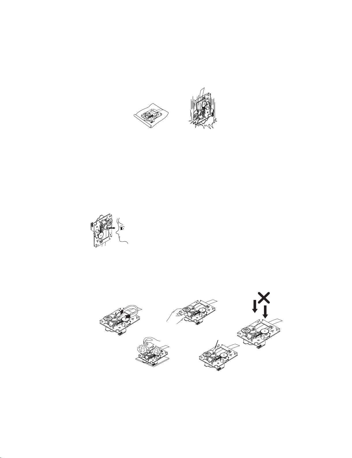
1. Notes for transport and storage
1) The pick-up should always be left in its conductive bag until immediately prior to use.
2) The pick-up should never be subjected to external pressure or impact.
Storage in conductive bag
Drop impact
2. Repair notes
1) The pick-up incorporates a strong magnet, and so should never be brought close to magnetic materials.
2) The pick-up should always be handled correctly and carefully, taking care to avoid external pressure and
impact. If it is subjected to strong pressure or impact, the result may be an operational malfunction and/or
damage to the printed-circuit board.
3) Each and every pick-up is already individually adjusted to a high degree of precision, and for that reason
the adjustment point and installation screws should absolutely never be touched.
4) Laser beams may damage the eyes!
Absolutely never permit laser beams to enter the eyes!
Also NEVER switch ON the power to the laser output part (lens, etc.) of the pick-up if it is damaged.
NEVER look directly at the laser beam, and don’t allow
contact with fingers or other exposed skin.
5) Cleaning the lens surface
If there is dust on the lens surface, the dust should be cleaned away by using an air bush (such as used
for camera lens). The lens is held by a delicate spring. When cleaning the lens surface, therefore, a cotton swab should be used, taking care not to distort lens.
Pressure
Magnet
How to hold the pick-up
Cotton swab
Conductive Sheet
6) Never attempt to disassemble the pick-up.
Spring has excess pressure. If the lens is extremely dirty, apply isopropyl alcohol to the cotton swab.
(Do not use any other liquid cleaners, because they will damage the lens.) Take care not to use too much
of this alcohol on the swab, and do not allow the alcohol to get inside the pick-up.
1-3
Copyright © 2019 LG Electronics Inc. All rights reserved.
Only for training and service purposes.
Pressure
NOTES REGARDING COMPACT DISC PLAYER REPAIRS
1. Preparations
1) Compact disc players incorporate a great many ICs as well as the pick-up (laser diode). These components
are sensitive to, and easily affected by, static electricity. If such static electricity is high voltage, components
can be damaged, and for that reason components should be handled with care.
2) The pick-up is composed of many optical components and other high-precision components. Care must be
taken, therefore, to avoid repair or storage where the temperature or humidity is high, where strong magnetism is present, or where there is excessive dust.
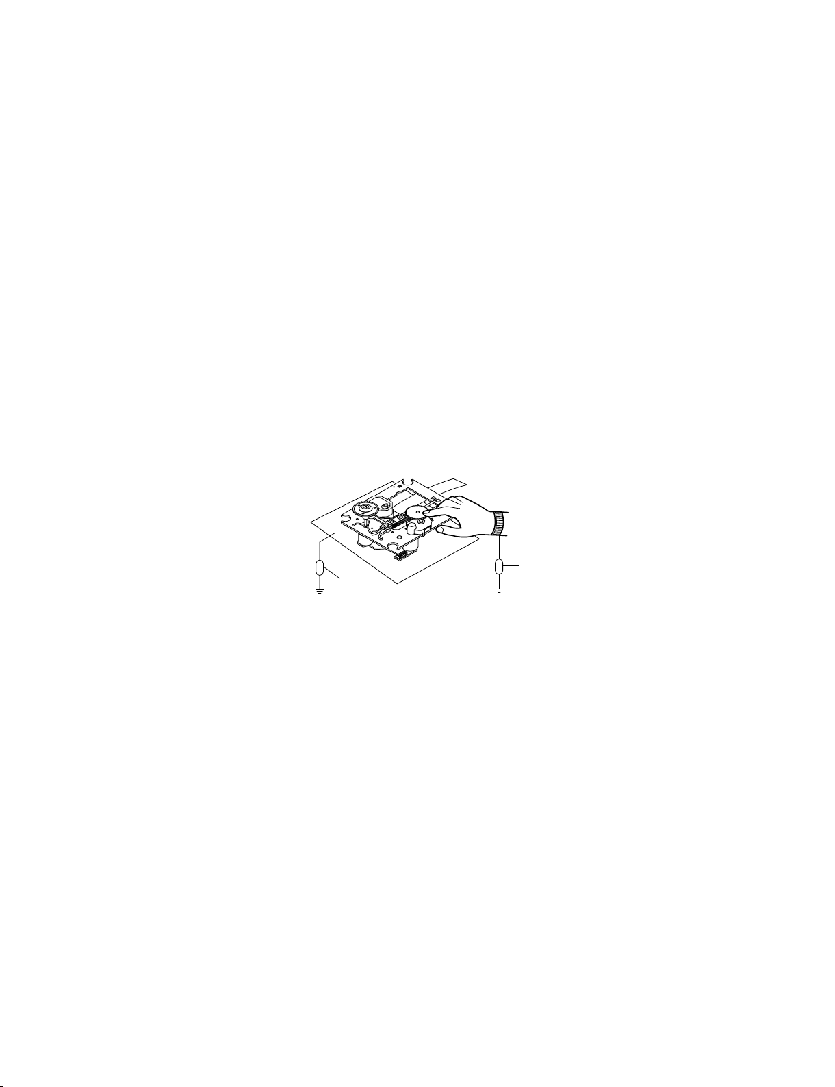
2. Notes for repair
1) Before replacing a component part, first disconnect the power supply lead wire from the unit
2) All equipment, measuring instruments and tools must be grounded.
3) The workbench should be covered with a conductive sheet and grounded.
When removing the laser pick-up from its conductive bag, do not place the pick-up on the bag. (This is
because there is the possibility of damage by static electricity.)
4) To prevent AC leakage, the metal part of the soldering iron should be grounded.
5) Workers should be grounded by an armband (1 M)
6) Care should be taken not to permit the laser pick-up to come in contact with clothing, in order to prevent
static electricity changes in the clothing to escape from the armband.
7) The laser beam from the pick-up should NEVER be directly facing the eyes or bare skin.
Armband
Resistor
(1 M)
Resistor
(1 M)
Conductive
Sheet
1-4
Copyright © 2019 LG Electronics Inc. All rights reserved.
Only for training and service purposes.
ESD PRECAUTIONS
Electrostatically Sensitive Devices (ESD)
Some semiconductor (solid state) devices can be damaged easily by static electricity. Such components
commonly are called Electrostatically Sensitive Devices (ESD). Examples of typical ESD devices are integrated
circuits and some field-effect transistors and semiconductor chip components. The following techniques should
be used to help reduce the incidence of component damage caused by static electricity.
1. Immediately before handling any semiconductor component or semiconductor-equipped assembly, drain off
any electrostatic charge on your body by touching a known earth ground. Alternatively, obtain and wear a
commercially available discharging wrist strap device, which should be removed for potential shock reasons
prior to applying power to the unit under test.
2. After removing an electrical assembly equipped with ESD devices, place the assembly on a conductive surface
such as aluminum foil, to prevent electrostatic charge buildup or exposure of the assembly.
3. Use only a grounded-tip soldering iron to solder or unsolder ESD devices.
4. Use only an anti-static solder removal device. Some solder removal devices not classified as "anti-static" can
generate electrical charges sufficient to damage ESD devices.
5. Do not use freon-propelled chemicals. These can generate electrical charges sufficient to damage ESD
devices.
6. Do not remove a replacement ESD device from its protective package until immediately before you are
ready to install it. (Most replacement ESD devices are packaged with leads electrically shorted together by
conductive foam, aluminum foil or comparable conductive materials).
7. Immediately before removing the protective material from the leads of a replacement ESD device, touch the
protective material to the chassis or circuit assembly into which the device will by installed.
CAUTION : BE SURE NO POWER IS APPLIED TO THE CHASSIS OR CIRCUIT, AND OBSERVE ALL OTHER
SAFETY PRECAUTIONS.
8. Minimize bodily motions when handing unpackaged replacement ESD devices. (Otherwise harmless motion
such as the brushing together of your clothes fabric or the lifting of your foot from a carpeted floor can generate
static electricity sufficient to damage an ESD device).
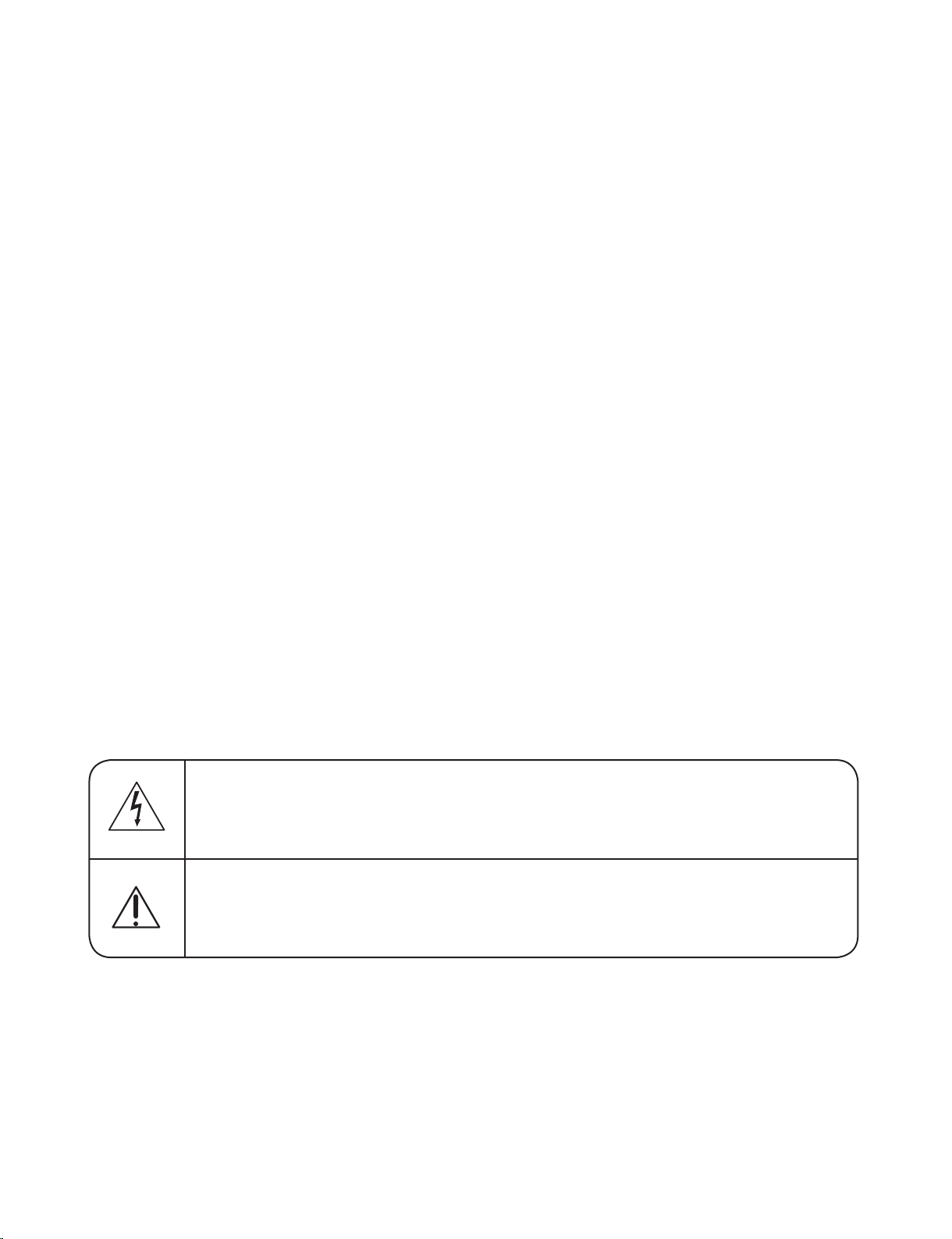
CAUTION. GRAPHIC SYMBOLS
THE LIGHTNING FLASH WITH APROWHEAD SYMBOL. WITHIN AN EQUILATERAL TRIANGLE, IS
INTENDED TO ALERT THE SERVICE PERSONNEL TO THE PRESENCE OF UNINSULATED
“DANGEROUS VOLTAGE” THAT MAY BE OF SUFFICIENT MAGNITUDE TO CONSTITUTE A RISK OF
ELECTRIC SHOCK.
THE EXCLAMATION POINT WITHIN AN EQUILATERAL TRIANGLE IS INTENDED TO ALERT THE
SERVICE PERSONNEL TO THE PRESENCE OF IMPORTANT SAFETY INFORMATION IN SERVICE
LITERATURE.
1-5
Copyright © 2019 LG Electronics Inc. All rights reserved.
Only for training and service purposes.

PROGRAM DOWNLOAD GUIDE
1. MAIN MCS PROGRAM (MAIN MCS CHIP)
Download program file name must be MAIN_OL55D_HAD_YYMMDDX.bin
If security program(Water Wall) is activated on PC, you must save the file to the USB storage device
and disable the security software, then download the file to your set.
Downloading file proceeds at USB function.
Caution:
When downloading the file, you should neither unplug the USB device, change to the other function,
nor power off the device. USB device must be unplugged when the downloading process is completed.
ON VFD DISPLAY SCREEN
NO USB
Insert USB device into Front USB Port at USB function.
SEARCH
FIRMWARE
FINISH
Auto POWER OFF
1) (Fast) Format USB device.
2) Copy Firmware file to USB device.
1-6
Copyright © 2019 LG Electronics Inc. All rights reserved.
Only for training and service purposes.

2. LED-MICOM PROGRAM
Download program file name must be MICOM_OL55D_HAD_YYMMDDX.HEX
If security program(Water Wall) is activated on PC, you must save the file to the USB storage device
and disable the security software, then download the file to your set.
Downloading file proceeds at USB function.
Caution:
When downloading the file, you should neither unplug the USB device, change to the other function,
nor power off the device. USB device must be unplugged when the downloading process is completed.
ON VFD DISPLAY SCREEN
NO USB
Insert USB device into Front USB Port at USB function.
SEARCH
MICOM UP
FINISH
Auto POWER OFF
1) (Fast) Format USB device.
2) Copy Firmware file to USB device.
1-7
Copyright © 2019 LG Electronics Inc. All rights reserved.
Only for training and service purposes.

3. MTK-MICOM PROGRAM
Download program file name must be OL45D_YYMMDDX.HEX
If security program(Water Wall) is activated on PC, you must save the file to the USB storage device
and disable the security software, then download the file to your set.
Downloading file proceeds at DVD/CD function.
Caution:
When downloading the file, you should neither unplug the USB device, change to the other function,
nor power off the device. USB device must be unplugged when the downloading process is completed.
ON VFD DISPLAY SCREEN
DVD/CD
USB
SEARCH
MICOM UP
1) (Fast) Format USB device.
2) Copy Firmware file to USB device.
Insert USB device into Backside Service USB Port at DVD/CD
function. Front ‘STOP’ + Remote control ‘6’ push same timing
during 5s.
FINISH
Auto POWER OFF
1-8
Copyright © 2019 LG Electronics Inc. All rights reserved.
Only for training and service purposes.

4. MTK PROGRAM
Download program file name must be LG_OL45DLD1_YYMMDDX.rom
*LD1: Europe, CIS, Israel(HYE Buyer), Australia, India, Latin America, Turkey
LD2: Asia
LD3: Korea
LD4: Indonesia
LD7: Arabic, Israel (SBITANY buyer)
LD8: Iran
If security program(Water Wall) is activated on PC, you must save the file to the USB storage device
and disable the security software, then download the file to your set.
Downloading file proceeds at DVD/CD function.
Caution:
When downloading the file, you should neither unplug the USB device, change to the other function,
nor power off the device. USB device must be unplugged when the downloading process is completed.
ON VFD DISPLAY SCREEN
DVD/CD
USB
SEARCH
UPGRADE
1) (Fast) Format USB device.
2) Copy Firmware file to USB device.
Insert USB device into Backside Service USB Port at DVD/CD
function. Front ‘STOP’ + Remote control ‘6’ push same timing
during 5s.
Push Front ‘Play/Pause’ or Remote control ‘Play’
MTK UP
FINISH
Auto POWER OFF
1-9
Copyright © 2019 LG Electronics Inc. All rights reserved.
Only for training and service purposes.

5. OPTION, EQ & DEMO PROGRAM
Download program file name must be OPTEQ_DEMO_OL55D_HAD_XXXX.BIN
If security program(Water Wall) is activated on PC, you must save the file to the USB storage device
and disable the security software, then download the file to your set.
Downloading file proceeds at USB function.
Caution:
When downloading the file, you should neither unplug the USB device, change to the other function,
nor power off the device. USB device must be unplugged when the downloading process is completed.
ON VFD DISPLAY SCREEN
NO USB
Insert USB device into Front USB Port at USB function.
SEARCH
OPT UP
EQDEMOUP
FINISH
1) (Fast) Format USB device.
2) Copy Firmware file to USB device.
Auto POWER OFF
1-10
Copyright © 2019 LG Electronics Inc. All rights reserved.
Only for training and service purposes.
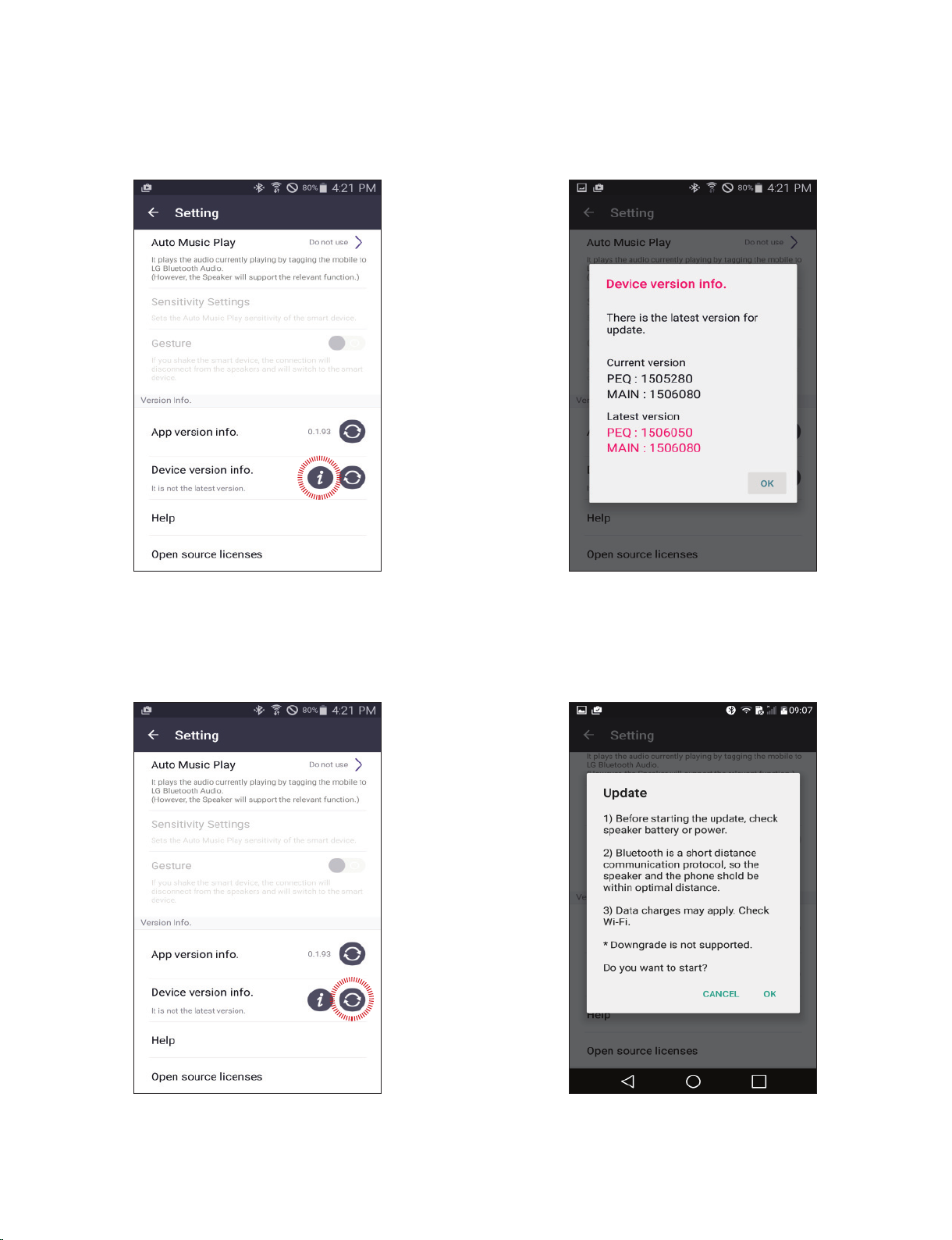
FOTA UPDATE STEP USING BT APP
Step1 : App connecting
(Check FW version)
After connecting the BT App with SET,
the user could fi nd the “Device Version info”
on Setting tab.
Step2 : Device version info
When touch the “Device Version info” button,
user could fi nd the current and latest SET
version on pop-up menu.
Step3 : Select update button
When touch the “Update” button, user could
update the SET fi rmware using FOTA.
Step4 : Confi rm update
Select the OK button on the caution message.
1-11
Copyright © 2019 LG Electronics Inc. All rights reserved.
Only for training and service purposes.
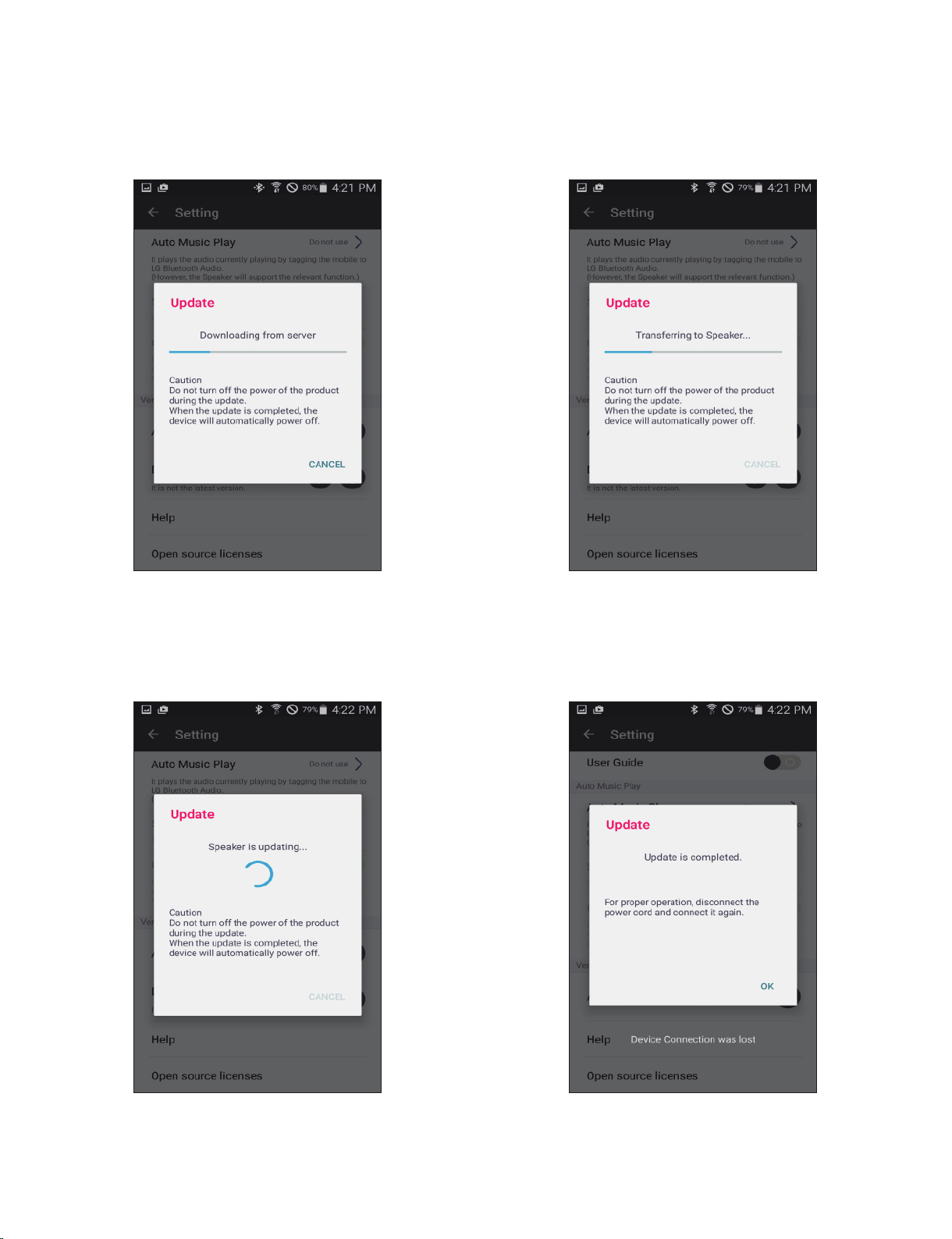
Step5 : Download from CDN server
Step6 : Transfer FW
1st step is download from CDN server to
smart phone. The progress bar is displayed
on BT App.
After completed the download from server,
smart phone start to transfer the fi rmware to the
SET. The progress bar is displayed on BT App.
Step7 : FW Flash Writing Step8 : FOTA complete
After completed the download from the smart
phone, the SET overwrite the fi rmware to fl ash
memory.
1-12
When fi nishing the fl ash memory writing, pop-up
message about fi nish is displayed and the SET
auto power off.
Copyright © 2019 LG Electronics Inc. All rights reserved.
Only for training and service purposes.

SPECIFICATIONS
GENERAL
Power requirements Refer to the main label on the unit.
Power consumption Refer to the main label on the unit.
Dimensions (W x H x D) Approx. 330 mm x 716 mm x 318 mm
Operating temperature 5 °C to 35 °C
Operating humidity 60 %
INPUTS/ OUTPUTS
Analog audio in (AUX IN) 1 kHz, RCA jack L/R x 1
Portable in (PORT. IN) 1 kHz, 3.5 mm Stereo jack x 1
Microphone (MIC 1/2) 1 kHz, 6.3 mm jack x 2
HDMI OUT (video/audio) 19pin(Type A, HDMI
TUNER
FM Tuning Range 87.5 to 108.0 MHz or 87.50 to 108.00 MHz
SYSTEM
Frequency Response 40 to 20,000 Hz
Signal-to-noise ratio More than 75 dB
Dynamic range More than 80 dB
Bus Power Supply (USB) 5 V 500 mA
TM
Connector ) x 1
AMPLIFIER (RMS Output power)
Total output 600 W RMS
High 193 W RMS x 2 (4 Ω at 1 kHz, THD 25 %)
Low 214 W(4 Ω at 200 Hz, THD 25 %)
Design and specifications are subject to change without notice.
1-13
Copyright © 2019 LG Electronics Inc. All rights reserved.
Only for training and service purposes.

1-14
Copyright © 2019 LG Electronics Inc. All rights reserved.
Only for training and service purposes.

SECTION 2
CABINET & MAIN CHASSIS
CONTENTS
DISASSEMBLY INSTRUCTIONS ..................................................................................................................... 2-2
MD FFC INSERTION GUIDE ............................................................................................................................. 2-8
EXPLODED VIEWS ........................................................................................................................................... 2-9
1. CABINET AND MAIN FRAME SECTION ................................................................................................. 2-9
2. PACKING ACCESSORY SECTION ....................................................................................................... 2-13
2-1
Copyright © 2019 LG Electronics Inc. All rights reserved.
Only for training and service purposes.
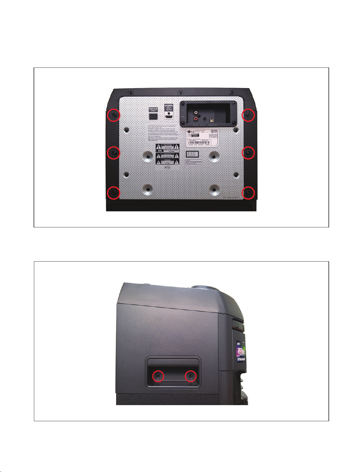
1) Remove the 6 screws.
DISASSEMBLY INSTRUCTIONS
Figure 1. Panel Side L/R disassembly - 1
2) Disassemble each of the two screws located inside the handle.
Figure 2. Panel Side L/R disassembly - 2
2-2
Copyright © 2019 LG Electronics Inc. All rights reserved.
Only for training and service purposes.
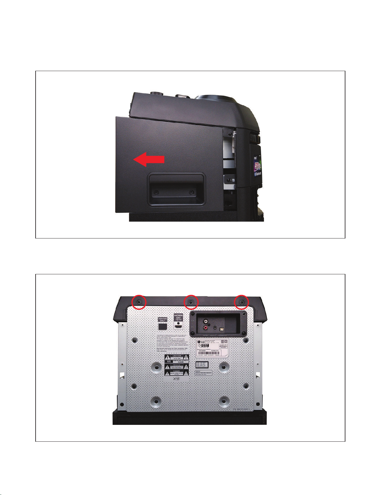
3) Pull out Cover Side Assembly L/R in the backward direction.
4) Remove the 3 screws.
Figure 3. Panel Side L/R disassembly - 3
Figure 4. Panel Top disassembly - 1
2-3
Copyright © 2019 LG Electronics Inc. All rights reserved.
Only for training and service purposes.
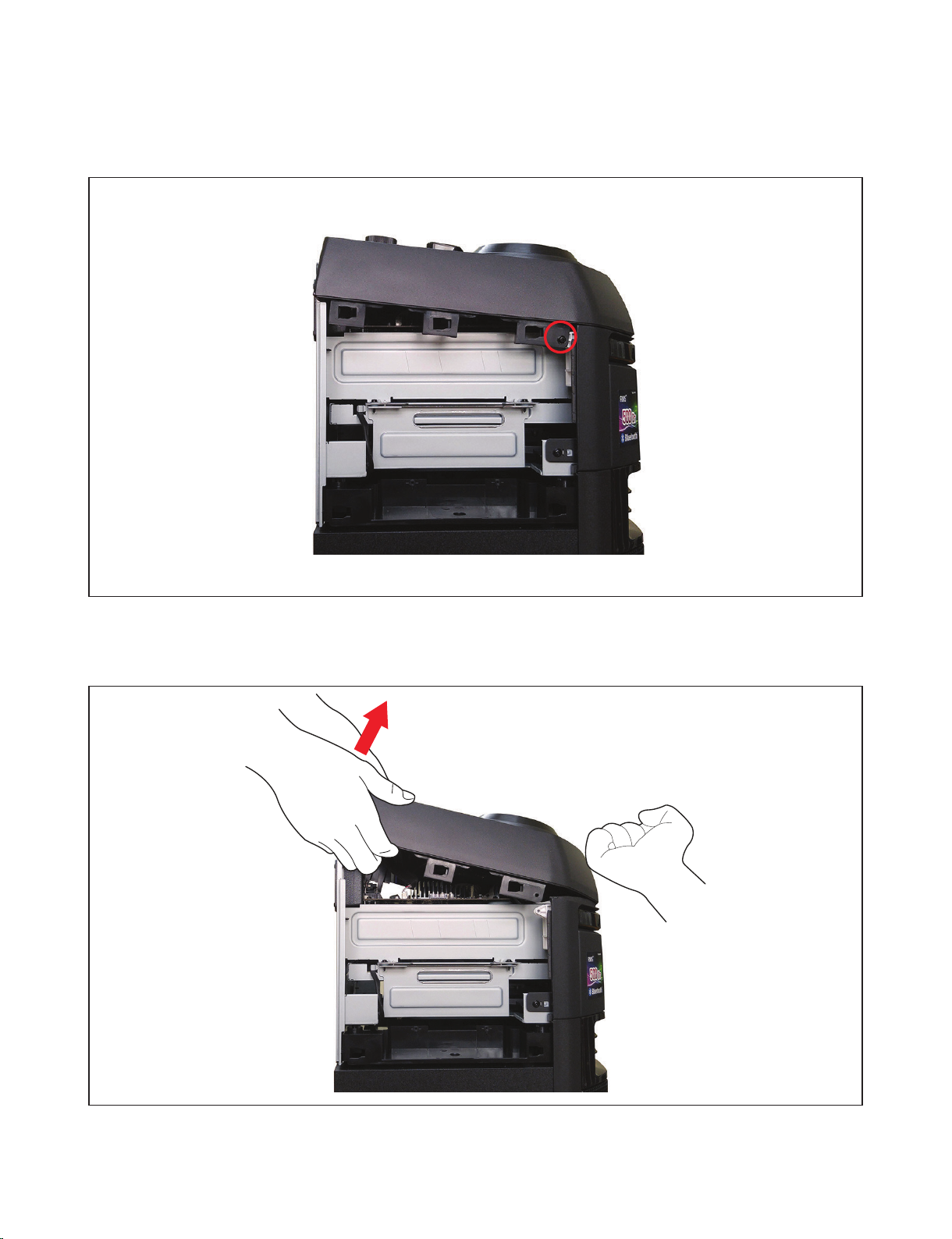
5) Remove the two screws on the left and right sides.
Figure 5. Panel Top disassembly - 2
6) As shown in the fi gure, remove the Panel Top by pushing the front part and lifting the rear part.
Figure 6. Panel Top disassembly - 3
2-4
Copyright © 2019 LG Electronics Inc. All rights reserved.
Only for training and service purposes.
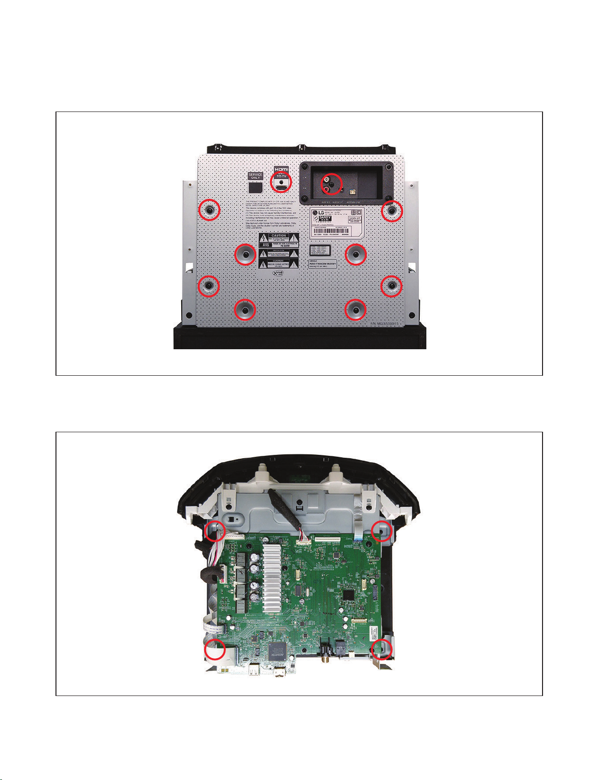
7) Remove the 9 screws on the Panel Rear.
Figure 7. Panel Rear disassembly
8) Bracket MD + Frame Main Screw 4 EA Disassembly
Figure 8. Main Set disassembly - 1
2-5
Copyright © 2019 LG Electronics Inc. All rights reserved.
Only for training and service purposes.
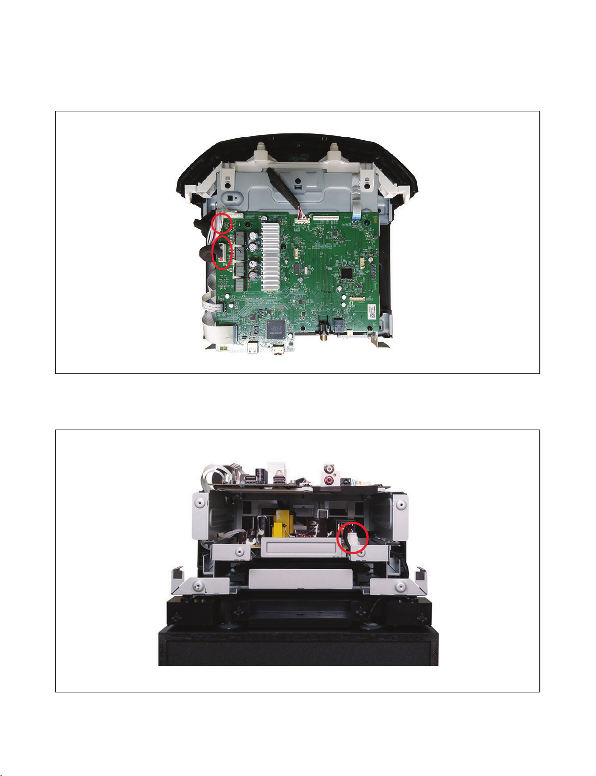
9) Remove the Set LED Connector / Speaker LED Connector / Speaker Network cable.
10) Power Cable Disconnection
Figure 9. Main Set disassembly - 2
Figure 10. Main Set disassembly - 3
2-6
Copyright © 2019 LG Electronics Inc. All rights reserved.
Only for training and service purposes.

11) Grasp both sides and pull upward to remove the assembly.
Figure 11. Main Set disassembly - 4
12) Complete removal of the Main Set.
Figure 12. After detaching the Main Set
2-7
Copyright © 2019 LG Electronics Inc. All rights reserved.
Only for training and service purposes.
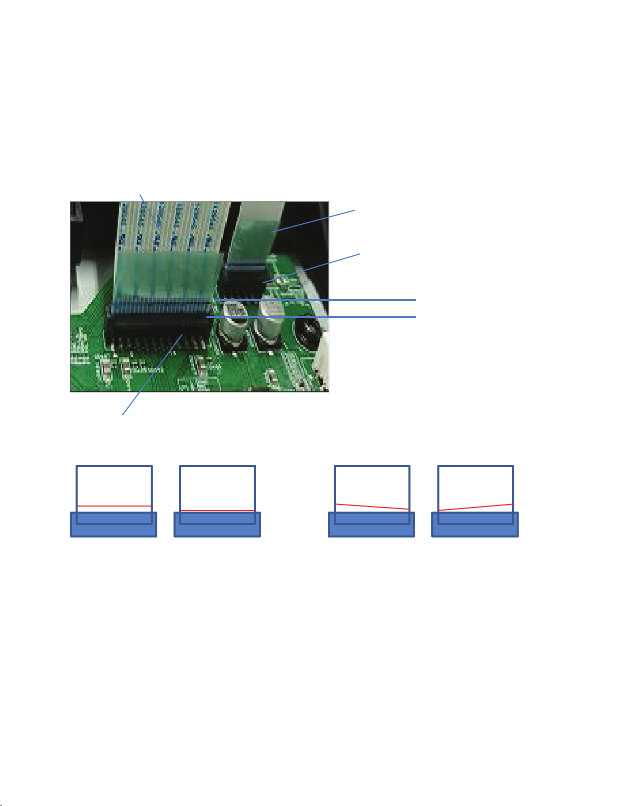
MD FFC INSERTION GUIDE
1. Insert FFC Cable_Pick Up into Connector_Pick Up until it is no longer inserted vertically.
(Also, insert FFC Cable_Loading into Connector_Pick Up with the same disinfection.)
2. Insert as shown in 1 and check the FFC Cable Line level of A based on B.
(A and B do not always match. )
FFC Cable_Pick UP
FFC Cable_Loading
Connector_ Loading
A : FFC Cable Line
B : Connector
Connector_Pick Up
))&/LQH
&RQQHFWRU
Case 1 : OK Case 2 : NG
))&/LQH
&RQQHFWRU
))&/LQH
&RQQHFWRU
))&/LQH
&RQQHFWRU
2-8
Copyright © 2019 LG Electronics Inc. All rights reserved.
Only for training and service purposes.
Copyright © 2019 LG Electronics Inc. All rights reserved.
Only for training and service purposes.
J
F
G
258
258
256
257
A44
266
A
MAIN
F
G
H
I
C
D
B
E
A46
C
A
L
L
I
H
A00
521
521
521
272
272
272
CABLE1
CN803
SMPS
K
K
BT
A51
CABLE3
B
E
J
CABLE5
A47
RMC
D
CABLE2
273
274
A50
A41
A60
270
TOP
251
251
259
300
A30
261
A31
276
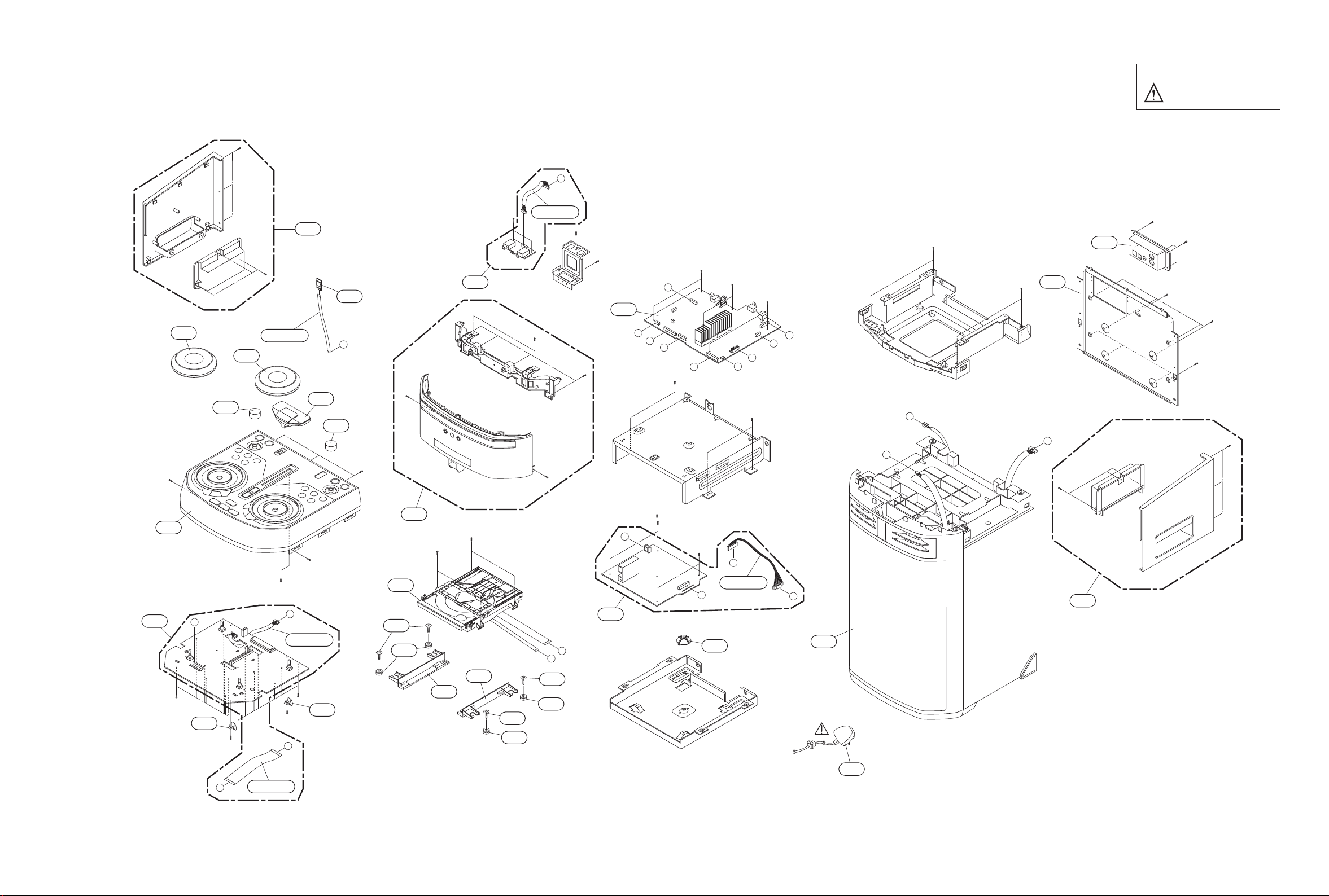
EXPLODED VIEWS
1. CABINET AND MAIN FRAME SECTION
2-9 2-10
NOTES) THE EXCLAMATION POINT WITHIN AN
EQUILATERAL TRIANGLE IS INTENDED
TO ALERT THE SERVICE PERSONNEL
TO THE PRESENCE OF IMPORTANT
SAFETY INFORMATION IN SERVICE
LITERATURE.
Copyright © 2019 LG Electronics Inc. All rights reserved.
Only for training and service purposes.
2-11 2-12
• Cabinet and main frame parts list
S AL LOCA. NO. PART NO. DESCRIPTION SPECIFICATION REMARKS
ASSEMBLY PARTS
A00 EAZ62761490 Deck Assembly,DVD DECK/MECHA [D3CM7]-DM19DC MD s
A30 ACQ90296703 Cover Assembly HOME OL55D Cover Side L Assy (
A31 ACQ90296803 Cover Assembly HOME OL55D Cover Side R Assy (
A41 EBR85315801 PCB Assembly OK75 JACK PCB Total Ass'y -
A44 ADV77505514 Frame Assembly HOME OL55D CIS LG logo 430C (
A46 EBR87839104 Option Code Assembly 11 13 65 02 05 00 00 4F 4C 37
A47 EBR86136101 PCB Assembly,Power OK55 220 Standard -
A50 EBR85824805 PCB Assembly OL55K STANDARD TOP PCB Total A
A51 EAT62833604 Module,Bluetooth MB8811C1TN CSR8811 Argentina H
A60 TCG37128055 Speaker System Total OL55K SPK SVC ASSEMBLY / RUSSI
INDIVISUAL PARTS
251 MGJ65381401 Plate,Ground PRESS SUS 0.3T PLATE GROUND CJ
256 AEZ75253402 Knob Assembly HOME OK55 Knob DJ L Assy (w/o
257 AEZ75253502 Knob Assembly HOME OK55 Knob DJ R Assy (w/o
258 MEY64574403 Knob MOLD ABS HOME OK Model MOLD VO
259 AEZ75253301 Knob Assembly HOME OK75 Knob Thruster Assy
261 AGL77333301 Panel Assembly,Front HOME OL55D WW (Without Model n
266 ACQ90439704 Cover Assembly SPK OL55D Jack Cover Assy (wit
270 AGL76373816 Panel Assembly,Rear OL55K CIS / HDMI jack, PC shee
272 MCQ68386802 Damper CUTTING BUTHYL 25 DECK/MECHA a
273 MEG65020201 Holder MOLD HIPS HOME OJ98 MOLD Holde
274 MEG65020301 Holder MOLD HIPS HOME OJ98 MOLD Holde
276 MEG63540502 Holder MOLD ABS HOME MINI/Onebody MOL
c 300 EAD61891001 Power Cord DE-2P-A-N-P-S-1550-N-00-BK-EU/
521 353-100AAAD Screw,Customized 353100AAAC BWH + 3mM 8mM SWCH1
CABLES
CABLE1 EAD63565003 Cable,FFC 25P125D-H0-1FA01-T-180-0-0-0-0
CABLE2 EAD63947302 Harness,Single HS-LG16-022 12005H00-08PL 1200
CABLE3 EAD62130037 Cable,FFC 10P010D-H2-1F00A-T-200-0-0-0-0
CABLE5 EAD63925702 Harness,Single HS-LG16-018 12504H00-12PL-HF 1
CN803 EAD42004424 Harness,Single HS-LG16-020 12005HOO-08PL 2200
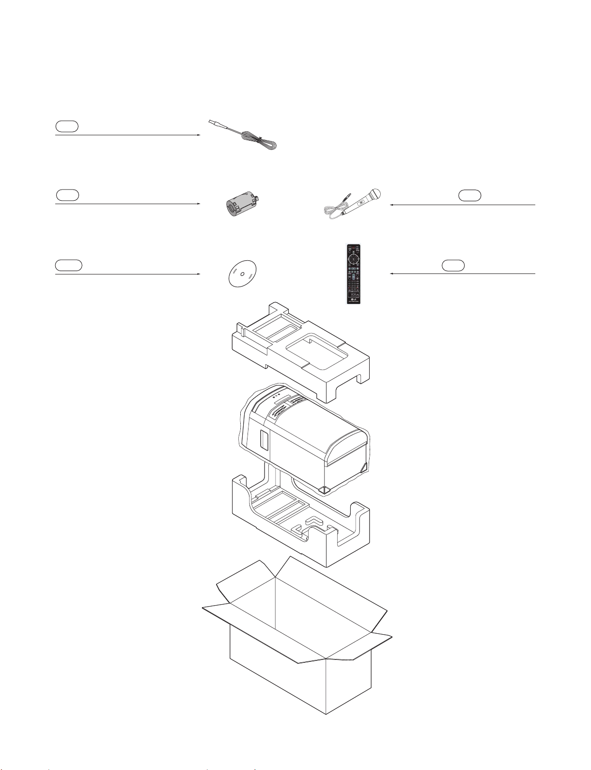
2. PACKING ACCESSORY SECTION
825 FM Wire Antenna
826 Filter, Ferrite Core
832S DVD Disc
O
N
827 Microphone
900 Remote Control
2-13
Copyright © 2019 LG Electronics Inc. All rights reserved.
Only for training and service purposes.
• Packing accessory parts list
S AL LOCA. NO. PART NO. DESCRIPTION SPECIFICATION REMARKS
825 EAA56671906 Antenna,T SN150184 SINGLE 0DB 0OHM 0 2M
826 6210VH0004C Filter,Ferrite Core 6210VH0004C(PE bag) 100OHM 30m
827 EAB60772003 Microphone Assembly GS-67 DYNAMIC MICROPHONE CAROL
832S EBA60658042 Blank Disk,DVD 2000 songs ver4. RA for DKS-20
900 AKB75655302 Remote Controller Assembly CB3 OL75K/55K, CL65K (CIS) SJ
2-14
Copyright © 2019 LG Electronics Inc. All rights reserved.
Only for training and service purposes.

SECTION 3 ELECTRICAL
CONTENTS
DIGITAL DISPLAY & MEDIA TRAINING MASTER ......................................................................................... 3-2
1. DISTORTED PICTURE ........................................................................................................................... 3-2
2. NO PICTURE .......................................................................................................................................... 3-7
3. PICTURE COLOR ................................................................................................................................. 3-12
4. NOISE/AUDIO PROBLEMS .................................................................................................................. 3-14
5. MISCELLANEOUS ................................................................................................................................ 3-17
ONE POINT REPAIR GUIDE .......................................................................................................................... 3-26
1. NO POWER .......................................................................................................................................... 3-26
2. VFD IS NOT DISPLAYED WHEN POWER ON THE SET ................................................................... 3-28
3. NO BOOTING WHEN POWER ON THE SET...................................................................................... 3-29
4. NO BOOTING (IN CD/USB FUNCTION) .............................................................................................. 3-30
5. NO OPERATION OF MD ...................................................................................................................... 3-33
6. NO SOUND ........................................................................................................................................... 3-38
7. NO BOOTING WHEN YOU TURN THE UNIT ON, NO MESSAGE ON FRONT PANEL.................... 3-47
8. BAD HDMI VIDEO/ AUDIO OUTPUT ................................................................................................... 3-50
ELECTRICAL TROUBLESHOOTING GUIDE ................................................................................................. 3-51
1. POWER (SMPS) ................................................................................................................................... 3-51
2. MCS PART CHECK .............................................................................................................................. 3-54
3. FLD DISPLAY CHECK ......................................................................................................................... 3-55
4. PWM MODULATION CHECK ............................................................................................................... 3-56
5. POWER AMP PART CHECK ............................................................................................................... 3-57
6. TUNER / AUX FUNCTION CHECK ...................................................................................................... 3-58
7. TUNER FUNCTION CHECK................................................................................................................. 3-58
8. CD FUNCTION CHECK ........................................................................................................................ 3-59
9. DOUBLE USB FUNCTION ................................................................................................................... 3-60
WAVEFORMS OF MAJOR CHECK POINT .................................................................................................... 3-61
1. SDRAM ................................................................................................................................................. 3-61
2. AUDIO PATH ........................................................................................................................................ 3-62
3. USB ....................................................................................................................................................... 3-63
4. SERVO .................................................................................................................................................. 3-63
5. SYSTEM PART (MPEG CRYSTAL 27 MHz) ....................................................................................... 3-64
6. SDRAM CLOCK .................................................................................................................................... 3-64
7. HDMI PART .......................................................................................................................................... 3-65
8. SERVO OPEN/CLOSE SIGNAL ........................................................................................................... 3-66
WIRING DIAGRAM .......................................................................................................................................... 3-75
BLOCK DIAGRAM .......................................................................................................................................... 3-77
CIRCUIT VOLTAGE CHART ........................................................................................................................... 3-79
1. IC VOLTAGE ......................................................................................................................................... 3-79
2. CAPACITOR VOLTAGE ....................................................................................................................... 3-80
3. CONNECTOR VOLTAGE ..................................................................................................................... 3-81
PRINTED CIRCUIT BOARD DIAGRAMS ....................................................................................................... 3-85
1. SMPS P.C.BOARD DIAGRAM ............................................................................................................. 3-85
2. MAIN P.C.BOARD DIAGRAM .............................................................................................................. 3-89
3. TOP P.C.BOARD DIAGRAM ................................................................................................................ 3-93
4. JACK & RMC P.C.BOARD DIAGRAM ................................................................................................. 3-97
5. SPEAKER LED P.C.BOARD DIAGRAM .............................................................................................. 3-97
3-1
Copyright © 2019 LG Electronics Inc. All rights reserved.
Only for training and service purposes.
DIGITAL DISPLAY & MEDIA TRAINING MASTER
Objective: To provide clear and concise guidelines for customer service agents to handle calls on
box goods calls.
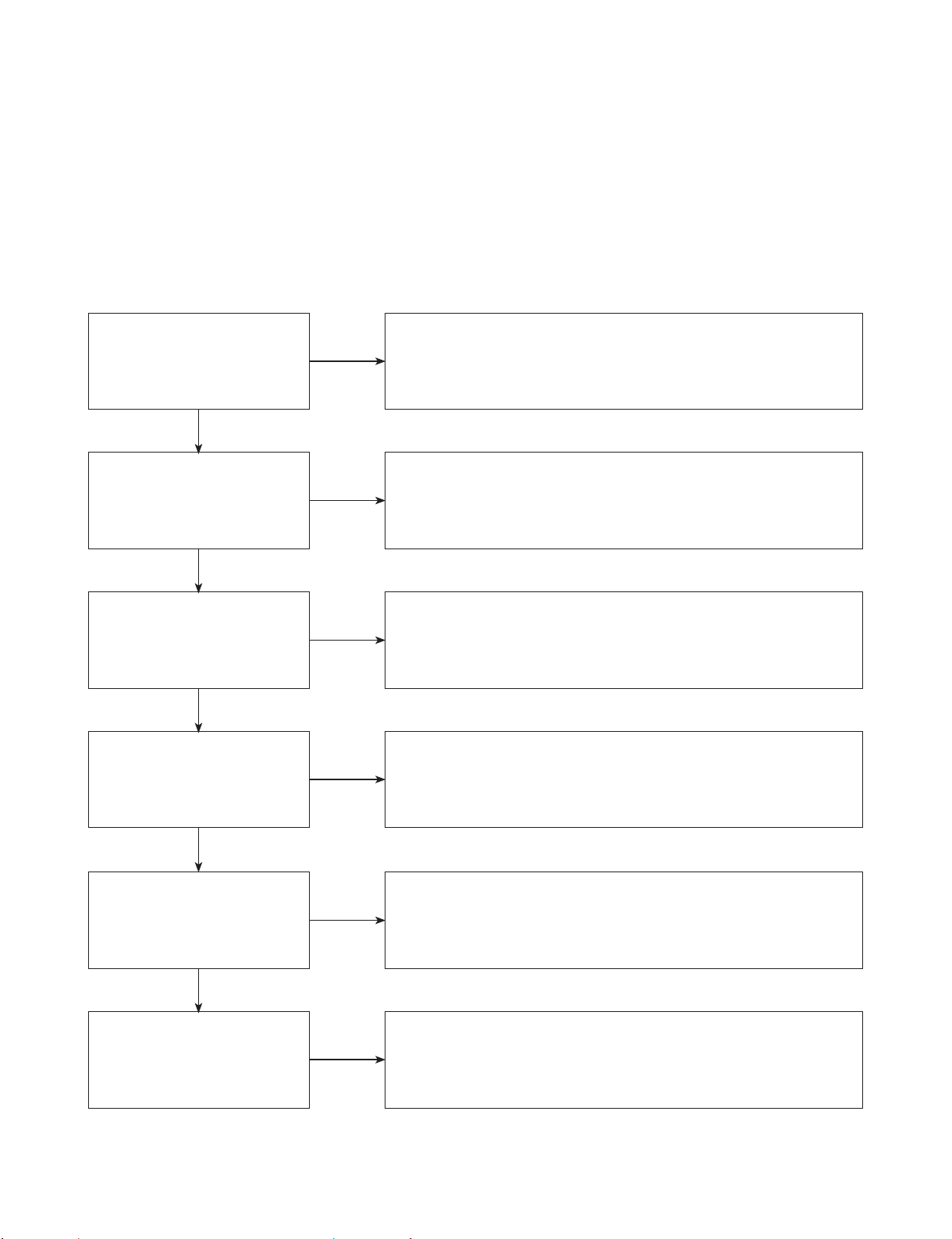
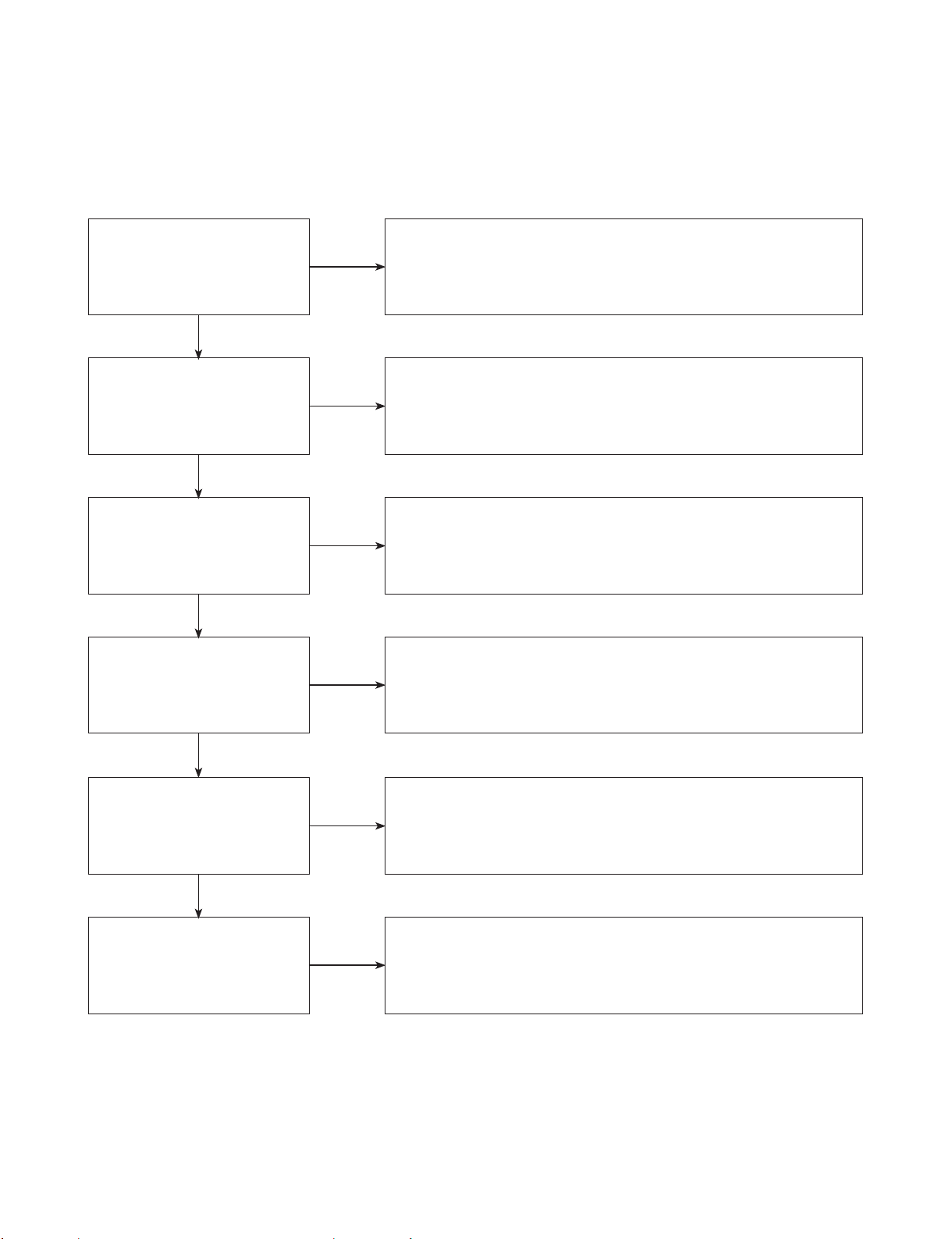
1. DISTORTED PICTURE
1-1. Lines on Picture
Distorted picture refers to the customer getting video, but there is a problem with the video.
Determine what cables the customer is using to connect
What cables is
the customer using to
connect the DVD?
YES
NO
the DVD to the TV and if connected properly. Refer to OM for
connections. Tighten any loose cables. Make sure the customer
is not connecting a DVD to VCR.
Copy protection can distort the picture on older DVD models.
Is the TV set
to the correct input?
YES
Do lines appear when
watching multiple discs?
YES
Do lines appear when
watching a TV program?
YES
Do lines appear
when the DVD is
connected to another TV?
NO
NO
NO
NO
Make sure the TV is on the correct input.
Turn TV off, then on to determine input.
Video when using composite, or component.
DVI when using DVI, and HDMI when using HDMI.
One disc displaying the issue is a problem with the disc.
Multiple discs displaying the problem could indicate the DVD lens
needs to be cleaned. Recommend the customer use a lens
cleaner on the DVD. A lens cleaner is available at any local
electronics retailer.
Lines appearing when watching a TV program indicates
an issue with the display. If the TV program is fine,
then connect the DVD to another input on the display to
determine if the problem is following the DVD.
Connect the DVD to another TV and play a disc.
No lines during disc play back indicates a problem with the first TV.
Please refer to the owners manual for instructions on how to
connect the DVD to a TV. If the DVD has a problem on the
second TV, then see service chart for service information.
YES
Has the customer tried
another set of cables?
NO
Have the customer try another set of cables. A bad cable can
also cause video problems. Test the cable with another device to
the TV to also determine if the TV is bad. If DVD is problem,
please see service chart for service information.
3-2
Copyright © 2019 LG Electronics Inc. All rights reserved.
Only for training and service purposes.
DIGITAL DISPLAY & MEDIA TRAINING MASTER
1-2. Ghost Picture
Distorted picture refers to the customer getting video, but there is a problem with the video.
Determine what cables the customer is using to connect the DVD to
What cables is the customer
using to connect the DVD?
YES
NO
the TV and if connected properly. Refer to OM for connections.
Tighten any loose cables. Make sure the customer is not connecting a
DVD to VCR or DVD. Copy protection can distort
the picture on older VCR models.
Is the TV set to
the correct input?
YES
Do ghosting appear when
watching multiple discs?
YES
Do lines appear when
watching a TV program?
YES
Does ghosting
appear when the DVD is
connected to another TV?
NO
NO
NO
NO
Make sure the TV is on the correct input. Turn TV off,
then on to determine input. Video when using composite,
or component. DVI when using DVI, and HDMI when using HDMI.
One disc displaying the issue is a problem with the disc.
Multiple discs displaying the problem could indicate the DVD lens
needs to be cleaned. Recommend the customer use a lens cleaner
on the DVD. A lens cleaner is available at any local electronics retailer.
Ghosting appearing when watching a TV program indicates an
issue with the display. If the TV program is fine, then connect
the DVD to another input on the display to determine
if the problem is following the DVD.
Connect the DVD to another TV and play a disc.
No ghosting during disc play back indicates a problem with the first TV.
Please refer to the owners manual for instructions on how to
connect the DVD to a TV. If the DVD has a problem on the second TV,
then see service chart for service information.
YES
Has the customer tried
another set of cables?
NO
Have the customer try another set of cables. A bad cable can
also cause video problems. Test the cable with another device to
the TV to also determine if the TV is bad. If DVD is problem,
please see service chart for service information.
3-3
Copyright © 2019 LG Electronics Inc. All rights reserved.
Only for training and service purposes.
 Loading...