

LG N1910LZ Owner's Manual

www.lg.com
OWNER'S MANUAL
NETWORK MONITOR
N1910LZ
Please read the safety information carefully before using the product.
Network Monitor Model
English

2
ENG
English
Table of Contents
TABLE OF CONTENTS
3 ASSEMBLING AND
PREPARING
3 Unpacking
4 Parts and buttons
6 Setting Up the Monitor set
6 - Attaching the Stand Base
6 - Detaching the stand base
7 - Adjusting the stand height
7 - Adjusting the angle
8 - Mounting on a table
8 - Using the Kensington locking device
9 - Detaching the stand body
9 - Installing the wall mount plate
10 - Mounting on a wall
11 USING THE MONITOR SET
11 Connecting Input Signal Cable
11 - D-SUB IN connection - PC
11 - D-SUB OUT connection - PCoIP
12 - DVI connection - PCoIP
13 Connecting LAN/Peripherals
13 - LAN connection - PCoIP
14 - Peripheral device connection
15 - Self Image Adjustment
16 CUSTOMIZING SETTINGS
16 Accessing The Main Menus
17 MENU Settings
17 - Picture
18 - Color
19 - Display
20 - Others
21 MODE Settings
21 - F-ENGINE
22 - PHOTO EFFECT
23 AUTO Settings : D-SUB Input
23 -/ /- Settings : PCoIP Input
24 TROUBLESHOOTING
26 PRODUCT SPECIFICATION
27 Preset Mode
27 Power Indicator
28 PROPER POSTURE
28 Proper posture for using the monitor
29 USING PCOIP SOLUTION

3
ENG
English
ASSEMBLING AND PREPARING
ASSEMBLING AND PREPARING
Unpacking
Please check whether all the components are included in the box before using the product. If there are
missing components, contact the retail store where you purchased the product. Note that the product and
components may look different from those shown here.
y
Only use an approved LG power adapter.
y
Damage caused by other power adapters is not covered by warranty.
y
Note that the components may look different from those shown here.
y
Without prior notice, all information and specifications in this manual are subject to change to improve
the performance of the product.
y
To purchase optional accessories, visit an electronics store or online shopping site or contact the retail
store where you purchased the product.
Power CordUser Manual/Card
Stand Base
Adaptor
CAUTION
NOTE
15-pin D-SUB Signal Cable
4
ENG
English
ASSEMBLING AND PREPARING
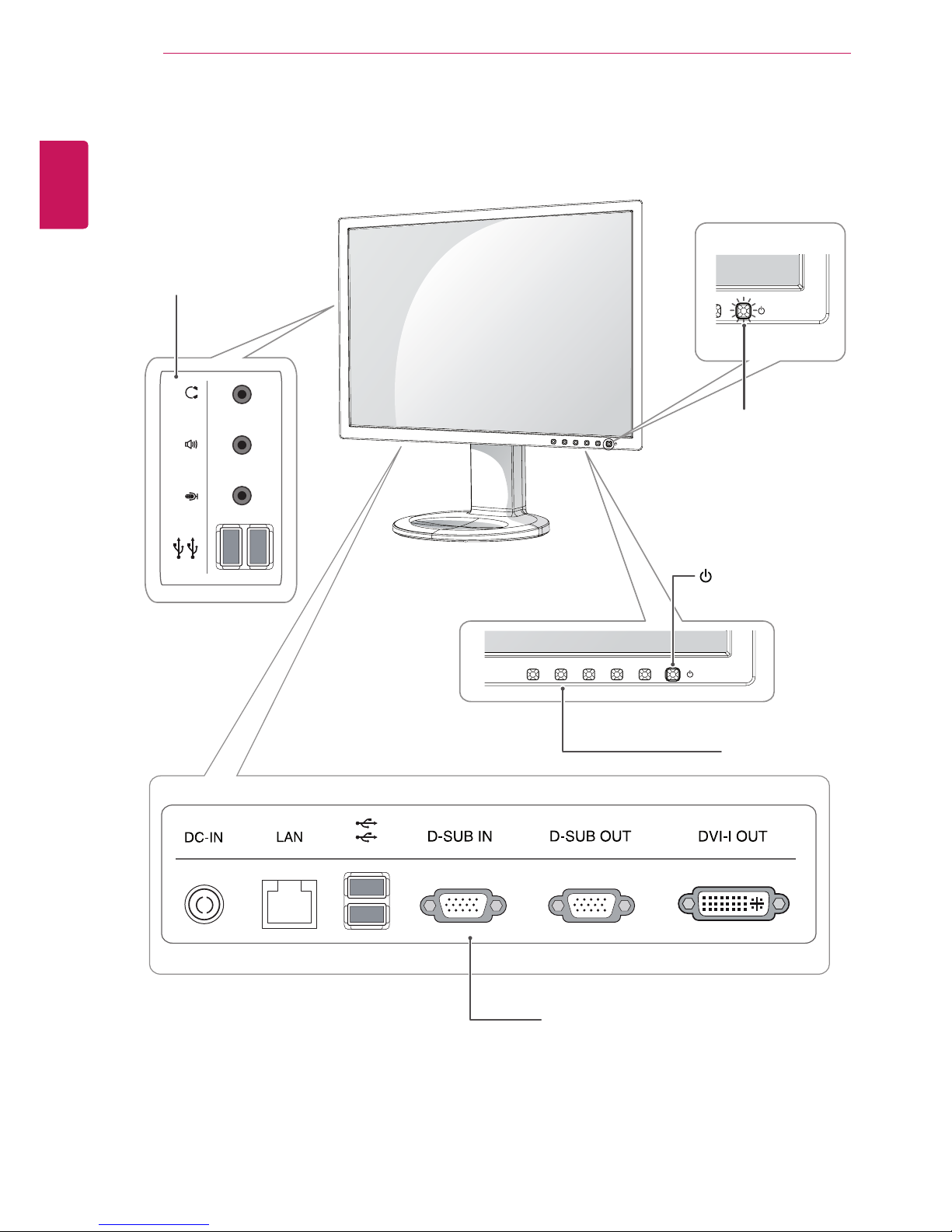
Parts and buttons
Power Indicator
y
LED On : Power is on
y
LED Off: Power is off
Front Side Buttons
Input Connectors (See p.11 to 14)
(Power Button)
Input Connectors
(See p.14 )

5
ENG
English
ASSEMBLING AND PREPARING
Button Description
MENU Activates the main menu.
OSD Lock/Unlock
Functions
Locks/unlocks the OSD screen.
yTo lock the OSD screen, press and hold the MENU button
for several seconds. The "OSD LOCKED" message will be
displayed and the screen will be locked.
yTo unlock the OSD screen, press and hold the MENU
button again for several seconds. The "OSD UNLOCKED"
message will be displayed and the screen will be unlocked.
MODE Moves to the F-ENGINE and PHOTO EFFECT options.
AUTO To adjust the monitor settings, press the AUTO button on the MONITOR SETUP OSD
menu (only supported for analog signal).
For optimal screen display, use the following resolution.
Optimal Resolution 1280 x 1024
INPUT Allows selection of the input signal.
yIf you connect the monitor to a computer using a D-SUB cable, select either the PCoIP
or D-SUB input signal.
yIf only one computer is connected to the monitor, the input signal is detected automati-
cally. The initial input signal is PCoIP.
EXIT Exits the OSD menu.
(Power Button)
yD-SUB Input: Power On/Off
yPCoIP Input
Monitor Off: Press the power button twice, or press the power button and wait for 10
seconds.
PCoIP Off: Press the power button, then press the EXIT button located next to the
power button.
PCoIP On: Press the power button.
Remote PC Power Control: Press the power button for at least five seconds to turn
the PC on/off.
* To use the Remote PC Power Control function, separate settings are required for the PC.
Power Indicator When the monitor is in operating mode, the power indicator
will turn white (on mode).
When the monitor is in power saving mode, the power indicator will blink white.

6
ENG
English
ASSEMBLING AND PREPARING
y
The components appearing in the illustrations may look different from the actual product.
y
Do not carry the monitor upside-down as this
may cause it to fall off its stand, resulting in
damage or injury.
y
To avoid damaging the screen when lifting
or moving the monitor, only hold the stand or
the plastic cover. This avoids putting unnecessary pressure on the screen.
y
Only remove the tape and the locking pin
when the monitor is mounted on the stand
base and is in an upright position. Otherwise,
the stand body may protrude, which may
lead to injury.
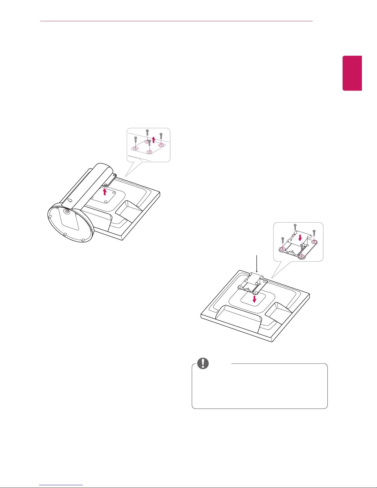
Detaching the stand base
1
Place the monitor's screen face down.
To protect the screen from scratches, cover the
surface with a soft cloth.
Setting Up the Monitor set
Attaching the Stand Base
1
Place the monitor's screen face down.
y
To protect the screen from scratches, cover
the surface with a soft cloth.
3
Using a coin, turn the screw clockwise to se-
cure the stand base.
2
Check the position (at the front and rear) of
the stand body, then mount the stand base on
the stand body as shown in the figure.
Stand Body
Stand Base
Stand Base
2
Using a coin, turn the screw in the stand base
counterclockwise. Detach the stand base from
the stand body.
Stand Body
Stand Base
CAUTION
CAUTION

7
ENG
English
ASSEMBLING AND PREPARING
y
Once the pin is removed, it is not necessary
to re-insert it to adjust the height.
Adjusting the stand height
1
Place the monitor mounted on the stand base
in an upright position.
Adjusting the angle
1
Place the monitor mounted on the stand base
in an upright position.
2
Remove the tape attached at the bottom rear
of the stand body, then pull out the locking
pin.
3
The height can be adjusted up to 110 mm.
2
Adjust the angle of the screen. The angle of the
screen can be adjusted up to 15° forwards and
5° backwards for a comfortable viewing experience.
y
To avoid injury to the fingers when adjusting
the screen, do not hold the lower part of the
monitor's frame as illustrated below.
y
Do not put your finger between the screen and the
base (chassis) when adjusting the screen's height.
y
Be careful not to touch or press the screen
area when adjusting the angle of the monitor.
Front Side Rear Side
15- 5
Tape
Locking Pin
Stand Body
110.0 mm
CAUTION
WARNING
WARNING

8
ENG
English
ASSEMBLING AND PREPARING
Mounting on a table
1
Lift the monitor and place it on the table in an
upright position.
Install at least 10 cm away from the wall to
ensure sufficient ventilation.
2
Connect the adaptor to the monitor, then plug
the power cord into the wall outlet.
3
Press the (Power) button on the front of the
monitor to turn on the monitor.
10 cm
10 cm
10 cm
10 cm
y
Unplug the power cord prior to moving or
installing the monitor. There is risk of electric
shock.
Using the Kensington locking
device
The connector for the Kensington lock is located
on the rear of the monitor.
For more information on installation and usage,
refer to the Kensington lock user manual or visit
the website at http://www.kensington.com.
Connect the monitor to the table with the Kensing-
ton lock cable.
y
Using the Kensington lock is optional. The
accessories can be purchased at your local
electronics store.
CAUTION
NOTE
9
ENG
English
ASSEMBLING AND PREPARING
Installing the wall mount plate
This monitor has a VESA compatible mount on the
back. Most mounts will require an LG mounting
plate.
Detaching the stand body
1
Place the monitor's screen face down. To
protect the screen from scratches, cover the
surface with a soft cloth.
2
Using a screwdriver, remove the four screws
and detach the stand from the monitor.
1
Place the monitor's screen face down. To
protect the screen from scratches, cover the
surface with a soft cloth.
2
Place the wall mount plate on the monitor and
align it with the screw holes on the monitor.
3
Using a screwdriver, tighten the four screws to
fix the plate onto the monitor.
y
The wall mount plate is sold separately.
y
For more information on the installation, refer
to the wall mount plate's installation guide.
Wall Mount Plate
NOTE
10
ENG
English
ASSEMBLING AND PREPARING
10 cm
10 cm
10 cm
10 cm
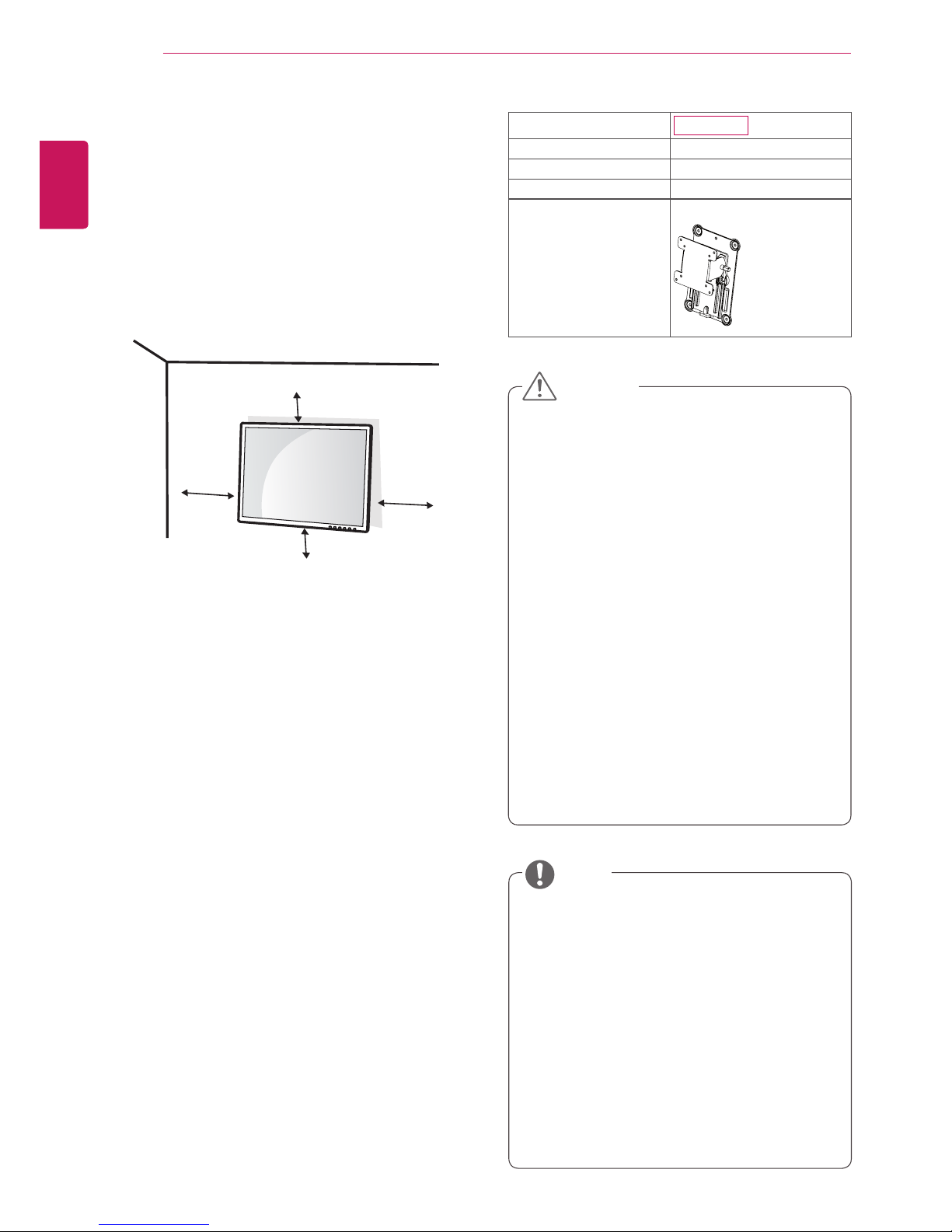
If you want to mount the monitor on the wall (optional), attach the wall mounting bracket to the rear
of the monitor.
Make sure that the wall mounting bracket is securely fixed to the monitor and to the wall.
Use the wall mount plate and screws that comply
with the VESA standard as specified below.
y
784.8 mm (30.9 inch) or less
* Thickness of the wall mount plate: 2.6 mm
* Fastening screw: Diameter 4.0 mm x Pitch 0.7
mm x
Length 10 mm
y
787.4 mm (31.0 inch) or greater
* Use the wall mount plate and screws con-
forming to the VESA standard.
y
Unplug the power cord before moving or installing the monitor to avoid electric shocks.
y
Installing the monitor on the ceiling or on a
slanted wall may result in the monitor falling
off, which could lead to injury. Please use
a LG wall mounting bracket when using a
VESA mount. For more information, contact
your local retail store or a qualified installer.
y
Applying excessive force when fastening
screws may cause damage to the monitor. Damage caused in this way will not be
covered by the product warranty.
y
Use the wall mounting bracket and screws
that conform to the VESA standard. Damage caused by the use or misuse of inappropriate components will not be covered
by the product warranty.
y
Use the screws specified in the VESA standard.
y
The wall mount kit includes the installation
guide and necessary parts.
y
The wall mounting bracket is optional. The
accessories can be purchased at your local
retail store.
y
The length of the screw may differ for each
wall mounting bracket. Ensure the correct
length of the screw is used.
y
For more information, please refer to the user
manual for the wall mounting bracket.
Model
N1910LZ
VESA (A x B)
75 x 75
Stand Screw
M4
Required Screw
4
Wall Mount Plate
(Optional)
RW120
Mounting on a wall
Install the monitor at least 10 cm away from the
wall and leave about 10 cm of space at each side
of the monitor to ensure sufficient ventilation. Detailed installation instructions can be obtained from
your local retail store. Please refer to the manual
to install and set up a tilting wall mounting bracket.
CAUTION
NOTE
11
ENG
English
USING THE MONITOR SET
USING THE MONITOR SET
Connecting Input Signal Cable
y
This monitor supports the *Plug and Play
feature.
*Plug and Play: A feature that allows you to
add a device to your computer, without having
to reconfigure anything or install any manual
drivers.
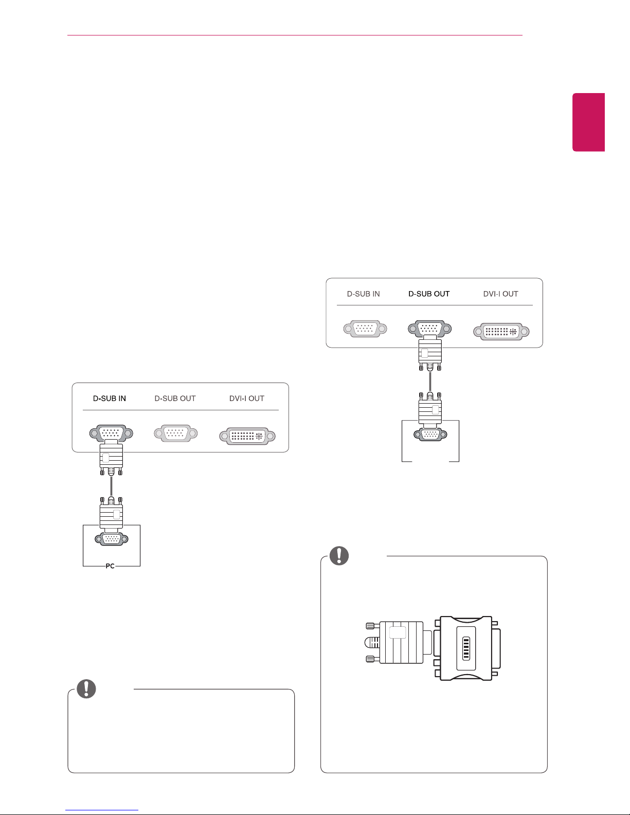
D-SUB IN connection - PC
D-SUB IN transfers analog video signals from the
PC to the monitor.
Connect the monitor to the PC using the provided
15-pin D-SUB signal cable as illustrated below.
y
Macintosh Adaptor: Use the standard Macintosh adaptor. Other commercial adaptors
may not be compatible (due to the signaling
difference).
y
When using a Macintosh D-SUB input cable
y
When using this device simply as a regular monitor through the RGB IN port, set
"PCoIP" to OFF in MENU > OTHERS to
reduce energy consumption.
NOTE
NOTE
RGB OUT
RGB OUT
RGB IN
MONITOR
D-SUB OUT connection - PCoIP
D-SUB OUT can only mirror the image displayed
on the monitor. (it does not support an extended
desktop).
Connect the monitor to the PC using the provided
15-pin D-SUB signal cable as illustrated below.
12
ENG
English
USING THE MONITOR SET
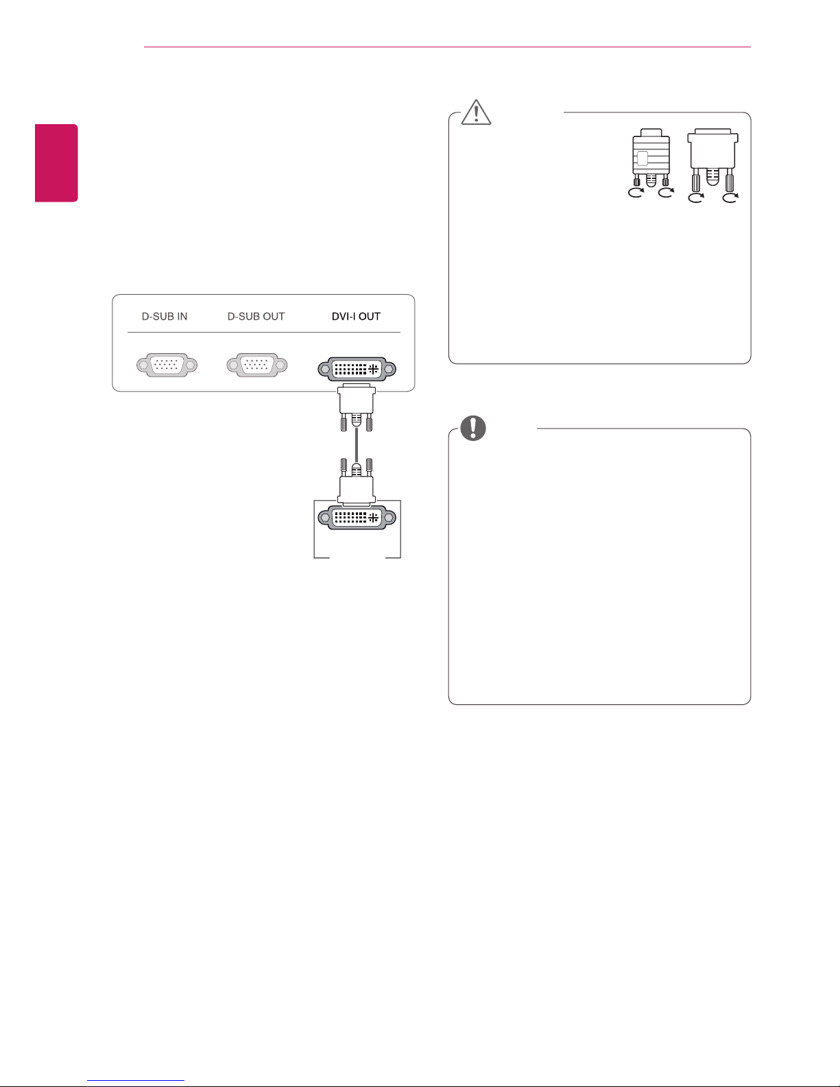
DVI connection - PCoIP
Transfers digital video signals to another monitor.
Connect the monitor using the DVI cable as illustrated below.
This connection is used to support an extended
monitor or replicate the image displayed on the
monitor.
y
To connect the monitor to a computer, use
the appropriate signal cable (LAN and DSUB).
y
A converter can be used to convert the DVI-I
input signal to D-SUB input signal.
y
When connecting the power cord to the outlet, use a grounded (3-hole) multi-socket or a
grounded wall outlet.
y
The monitor may flicker when turned on in an
area of low temperature. This is normal.
y
Sometimes red, green or blue spots may appear on the screen. This is normal.
y
Connect the input signal
cable and tighten in the
direction of the arrow. To
prevent disconnection
secure the cable tightly.
y
Do not press on the screen for a prolonged
time. This may cause image distortion.
y
Do not display a still image on the screen
for a prolonged time. This may cause image
retention. If possible, use the screen saver.
DVI-I(D) IN
MONITOR
CAUTION
NOTE
13
ENG
English
USING THE MONITOR SET
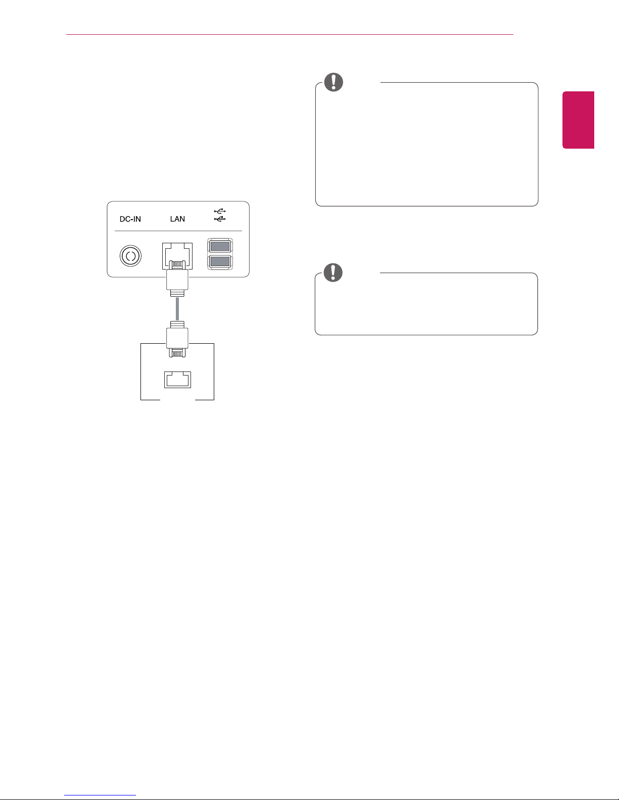
Connecting LAN/Peripherals
LAN connection - PCoIP
The LAN connection transmits PCoIP signals to
the monitor. Connect the router or switch to the
monitor using a LAN cable as illustrated below.
y
The LAN cable is sold separately.
y
The following LAN cable type can be used:
Standard: IEEE 802.3 ETHERNET
y
When connecting the Earphone Out or Line
Out through the LAN, use the volume icon on
the taskbar of your PC to adjust the volume.
y
Connect the LAN cable and the peripheral
devices prior to booting up the PC.
LAN
Hub/Router
NOTE
NOTE
 Loading...