

LG MT-42PZ40/V, MT-42PZ40/B, MT-42PZ40/R, MT-42PZ41/B, MT-42PZ40/S Service Manual
...
PLASMA MONITOR
SERVICE MANUAL
CAUTION
BEFORE SERVICING THE CHASSIS,
READ THE SAFETY PRECAUTIONS IN THIS MANUAL.
CHASSIS : RF-02RA
MODEL : MT-42PZ40/V/B/R/S
MODEL : MT-42PZ41/V/B/R/S/VB
MODEL : MT/MZ-42PZ42/V/B/R/S
MODEL : MT/MZ-42PZ43/V/B/R/S/VS
website:http://biz.LGservice.com
e-mail:http://www.LGEservice.com/techsup.html
Jan., 2003
Printed in KoreaP/NO : 3828VD0129E

- 2 -
CONTENTS
SAFETY PRECAUTIONS ...................................................................................3
DESCRIPTION OF CONTROLS ........................................................................ 4
SPECIFICATIONS .............................................................................................. 7
ADJUSTMENT INSTRUCTIONS ......................................................................10
BLOCK DIAGRAM.............................................................................................13
ASSEMBLY METHOD........................................................................................14
EXPLODED VIEW..............................................................................................16
EXPLODED VIEW PARTS LIST ........................................................................17
REPLACEMENT PARTS LIST...........................................................................18
SCHEMATIC DIAGRAM ........................................................................................
PRINTED CIRCUIT BOARD ..................................................................................
- 3 -
SAFETY PRECAUTIONS
Many electrical and mechanical parts in this chassis have special safety-related characteristics. These parts are identified by in
the Schematic Diagram and Replacement Parts List.
It is essential that these special safety parts should be replaced with the same components as recommended in this manual to
prevent X-RADIATION, Shock, Fire, or other Hazards.
Do not modify the original design without permission of manufacturer.
General Guidance
An isolation Transformer should always be used during
the servicing of a receiver whose chassis is not isolated from
the AC power line. Use a transformer of adequate power rating
as this protects the technician from accidents resulting in
personal injury from electrical shocks.
It will also protect the receiver and it's components from being
damaged by accidental shorts of the circuitry that may be
inadvertently introduced during the service operation.
If any fuse (or Fusible Resistor) in this monitor is blown, replace
it with the specified.
When replacing a high wattage resistor (Oxide Metal Film
Resistor, over 1W), keep the resistor 10mm away from PCB.
Keep wires away from high voltage or high temperature parts.
Due to high vacuum and large surface area of picture tube,
extreme care should be used in handling the Picture Tube.
Do not lift the Picture tube by it's Neck.
Leakage Current Cold Check(Antenna Cold Check)
With the instrument AC plug removed from AC source,
connect an electrical jumper across the two AC plug prongs.
Place the AC switch in the on position, connect one lead of
ohm-meter to the AC plug prongs tied together and touch other
ohm-meter lead in turn to each exposed metallic parts such as
antenna terminals, phone jacks, etc.
If the exposed metallic part has a return path to the chassis, the
measured resistance should be between 1MΩ and 5.2MΩ.
When the exposed metal has no return path to the chassis the
reading must be infinite.
An other abnormality exists that must be corrected before the
receiver is returned to the customer.
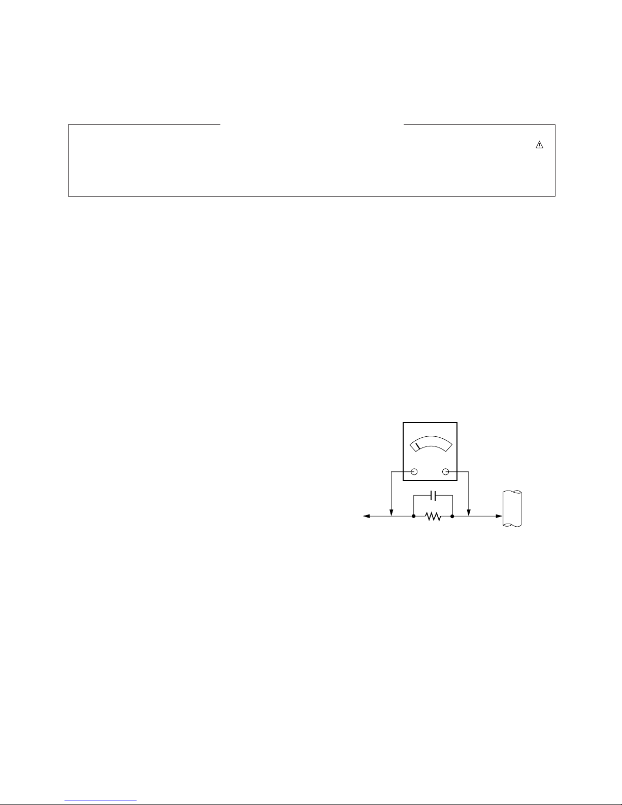
Leakage Current Hot Check (See below Figure)
Plug the AC cord directly into the AC outlet.
Do not use a line Isolation Transformer during this check.
Connect 1.5K/10watt resistor in parallel with a 0.15uF capacitor
between a known good earth ground (Water Pipe, Conduit, etc.)
and the exposed metallic parts.
Measure the AC voltage across the resistor using AC
voltmeter with 1000 ohms/volt or more sensitivity.
Reverse plug the AC cord into the AC outlet and repeat AC
voltage measurements for each exposed metallic part. Any
voltage measured must not exceed 0.75 volt RMS which is
corresponds to 0.5mA.
In case any measurement is out of the limits specified, there is
possibility of shock hazard and the set must be checked and
repaired before it is returned to the customer.
Leakage Current Hot Check circuit
1.5 Kohm/10W
To Instrument's
exposed
METALLIC PARTS
Good Earth Ground
such as WATER PIPE,
CONDUIT etc.
AC Volt-meter
IMPORTANT SAFETY NOTICE
0.15uF
- 4 -
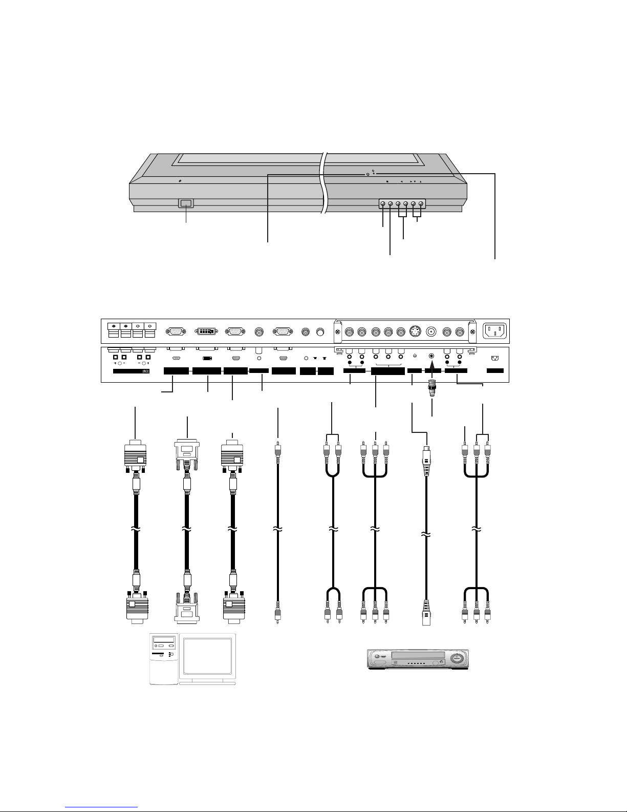
DESCRIPTION OF CONTROLS
<Back Panel>
<Front Panel Controls>
Connection to PC
Note: All cables shown are not provided with the Monitor, except:
A D-sub 15 pin cable and DVI cable is supplied to connect the Monitor to a PC.
Connection to AV equipment
( )( )
R
( )( )
L
REMOTE
CONTROL
RGB2 INPUT
(DIGITAL RGB INPUT)
RS-232C INPUT
(CONTROL/SERVICE)
EXTERNAL SPEAKER
LOCK
CONTROL
ON/ OFF
YPBP
R
(MONO)
R
AUDIO
L
R
AUDIO
L
S-VIDEO
VIDEO INPUT
AC INPUTAUDIO INPUTAUDIO INPUT
COMPONENT(480i/480p)
(DVD INPUT)
RGB1 INPUT
(PC INPUT)
RGB1 OUTPUT
(PC OUTPUT)
AUDIO INPUT
VOL.MENU
INPUT
SELECT
ON/OFF
Main Power Button
INPUT SELECT Button
VOLUME (F,G) Buttons
Power Standby Indicator
Illuminates red in standby mode,
Illuminates green when the
Monitor is turned on
Remote Control Sensor
MENU Button
D,E
Buttons
AUDIO
INPUT
VIDEO INPUT
S-VIDEO
INPUT
COMPONENT
AUDIO INPUT
RS-232C
INPUT
RGB2 INPUT
(DIGITAL
RGB INPUT)
RGB1
INPUT
(PC
INPUT)
RGB AUDIO
INPUT
COMPONENT(480i/480p)
(DVD INPUT)
- 5 -
( )( )
R
( )( )
L
REMOTE
CONTROL
RGB2 INPUT
(DIGITAL RGB INPUT)
RS-232C INPUT
(CONTROL/SERVICE)
EXTERNAL SPEAKER
LOCK
CONTROL
ON/ OFF
AC INPUT
RGB1 INPUT
(PC INPUT)
RGB1 OUTPUT
(PC OUTPUT)
AUDIO INPUT
AV1AV1
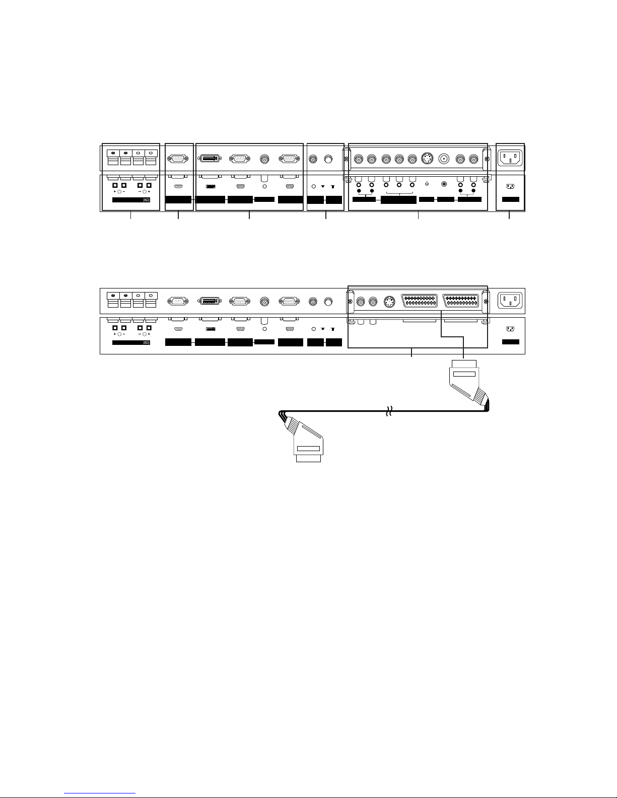
<Back Panel>
RCA Type
Scart Type
5
( )( )
R
( )( )
L
REMOTE
CONTROL
RGB2 INPUT
(DIGITAL RGB INPUT)
RS-232C INPUT
(CONTROL/SERVICE)
EXTERNAL SPEAKER
LOCK
CONTROL
ON/ OFF
Y PBP
R
(MONO)
R
AUDIO
L
R
AUDIO
L
S-VIDEO
VIDEO INPUT
AC INPUTAUDIO INPUTAUDIO INPUT
COMPONENT(480i/480p)
(DVD INPUT)
RGB1 INPUT
(PC INPUT)
RGB1 OUTPUT
(PC OUTPUT)
AUDIO INPUT
1 2 3 64 5
1. EXTERNAL SPEAKER (8 ohm output)
Connect to optional external speaker(s).
*For further information, refer to ÔSpeaker & Speaker StandÕ
manual.
2. RS-232C INPUT(CONTROL/SERVICE) PORT
Connect to the RS-232C port on a PC.
3. RGB2 INPUT(DIGITAL RGB INPUT)/RGB1 INPUT(PC
INPUT)/AUDIO INPUT SOCKET
Connect the monitor output socket of the PERSONAL COMPUTER to this socket.
RGB1 OUTPUT(PC OUTPUT) SOCKET
You can watch the RGB1 signal on another monitor, connect
RGB1 OUTPUT (PC OUTPUT) to another monitorÕs PC
input port. When the monitor is in standby mode, you can not
watch the RGB1 signal on another monitor.
4. CONTROL LOCK Switch
REMOTE CONTROL
When ÒCONTROL LOCKÓ is set ÒONÓ, Monitor is operated by
the external control device.
5. AUDIO / COMPONENT(480i/480p)(DVD INPUT) / S-VIDEO
/ VIDEO INPUT / AUDIO INPUT SOCKETS
EURO SCART SOCKET
Note : The interface board(AP-42EA40/41) is not equipped
on MT/MZ-42PZ42/43 series models. Contact your dealer
for buying this optional item.
6. POWER CORD SOCKET
This Monitor operates on an AC power. The voltage is indicated on the Specifications page. Never attempt to operate
the Monitor on DC power.

- 6 -
- When using the remote control aim it at the remote control sensor of the Monitor.
- There's maybe a defect in consecutive operation of remote control in specified brightness according to this monitor
feature.
¥ Open the battery compartment cover on the back side and
insert the batteries with correct polarity.
¥ Install two 1.5V alkaline batteries of AAA type. DonÕt mix used
batteries with new batteries.
Installing Batteries
1 2 3
4 5 6
7 8
0
9
POWER
SLEEP INPUT SELECT
PSM SSM
ARC
AUTO CONFIG.
ZOOM -
ZOOM +
SPLIT ZOOM
MENU MUTE
OK
VOL
POWER STOP
PLAY FF
REC
REW
P/STILL
PIP
TWIN PICTURE
PIP POSITION
PIP STILL
SOUND SELECT
PIP INPUT
VOL
CHILD LOCK
POWER
Switches the Monitor on from stand-
by or off to standby.
SLEEP
Sets the sleep timer.
PSM
Adjusts the factory preset picture
according to the room.
ARC
Changes the picture format.
ZOOM-
Reduces the main picture size.
SPLIT ZOOM
Enlarge the screen with regular
MENU
Displays on screen menus one by one.
Exits the current menu.
Memorizes menu changes.
NUMBER buttons
PIP
Switches the sub picture on
TWIN PICTURE
PIP INPUT
Selects the input mode for the
sub picture.
SOUND SELECT
Select main picture sound or
sub picture sound for PIP.
PIP POSITION
change the sub picture position.
PIP STILL
Freeze sub picture motion.
VCR BUTTONS
Controls a LG video cassette
recorder.
OK
DD/ EE
Selects a menu option.
FF/ GG
(Volume button)
Increases/decreases sound level.
Adjusts menu settings.
INPUT SELECT
SSM
To select the sound appropriate to
your viewing program character:
Flat, Speech, Movie, Music, or
User
AUTO CONFIG.
CHILD LOCK
To operate the monitor with remote
control only.
MUTE
Switches the sound on or off.
ZOOM+
Enlarges the main picture size.
- 7 -
SPECIFICATIONS
NOTE : Specifications and others are subject to change without notice for improvement
.
F Scope
This specification can be applied to all model of 42ÓPDP
MONITOR related to RF-02RA Chassis.
F Test Condition
1) Temperature : 20¡ 5¡C
2) Relative Humidity: 65¡ 10%
3) Power Voltage:Standard Input Voltage
(AC 100V-260V,~50/60Hz)
Rated Voltage(AC 100V-260V,~50/60Hz)
But Standard input voltage mark value is marked by model.
4) Follow each drawing or spec for spec and performance of
parts,based upon P/N of B.O.M
5)
Warm up set for more than 15min before the
measurement.
F Test and Inspection Method
1) Performance:Follow the Standard of LG TV test
2) Standards of Etc requirement
Safety: Follow the standard of UL1950,CSA1950
EMC: FCC PART 15 CLASS A/B(40: ClassB; 41,43: ClassA)
Appliance
OK
TEST,Not Applied
OK
Remark
Safety: IEC950,EN60590
EMC:
Safety: EN60590
EMC: CE
Model Name
MT-42PZ40/41
/42/43
MZ-42PZ42/43
Market
N-EU,China
EU
Chassis
RF-02RA
Brand
LG
LG
Model Name
MT-42PZ40/41/42/43
MZ-42PZ42/43
Market Place
N-EU, China
EU
Remark
Industry/Home use
Industry/Home use
- 8 -
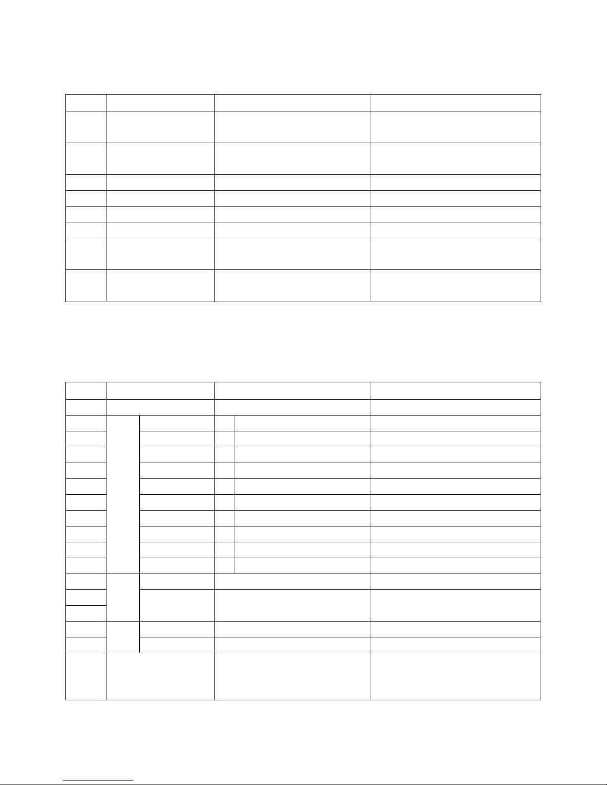
F Feature and Function
No
Item
Specification
Remark
1
2
3
4
5
6
7
8
9
10
11
12
13
14
15
16
Remote controller Code
External Control
RGB1 Input
RGB2 Input
RGB Audio input
RGB1 Output
Component input
Component Audio input
AV Input
S-video input
External Speaker Output
Auto Picture mode
User control
DASP
AVL
PIP(Picture In Picture)Mode
DW Mode
NEC Code
RS-232C
RGB-DTV,RGB-PC(Analog)
RGB-DTV(DVI),RGB-PC(Digital)
L/R
RGB-DTV,RGB-PC Throughout
Y,C
B/PB,CR/PR
L/R
Video/L/R
Y/C
L/R
Clear/ Soft/ User
Contrast/ Brightness/ Color/ Tint/
Sharpness/ Color Temperature
Flat/ Sports/ Cinema/ Music/ User
On/ Off
O
D-Sub 9 pin
D-Sub 15 pin
Earphone Jack
D-Sub 15pin
Video:BNC Jack,SCART1/2(MZ-42PZ43)
Spk terminal
Tint: Only NTSC-M
1)Main screen:RGB_PC/DVI
2)Sub screen: COMPONENT/AV/
S-VIDEO(480i),RGB-DTV(480P,720P,1080I)
Feature
Picture
Sound
1
1
1
1
1
1
1
1
1
2
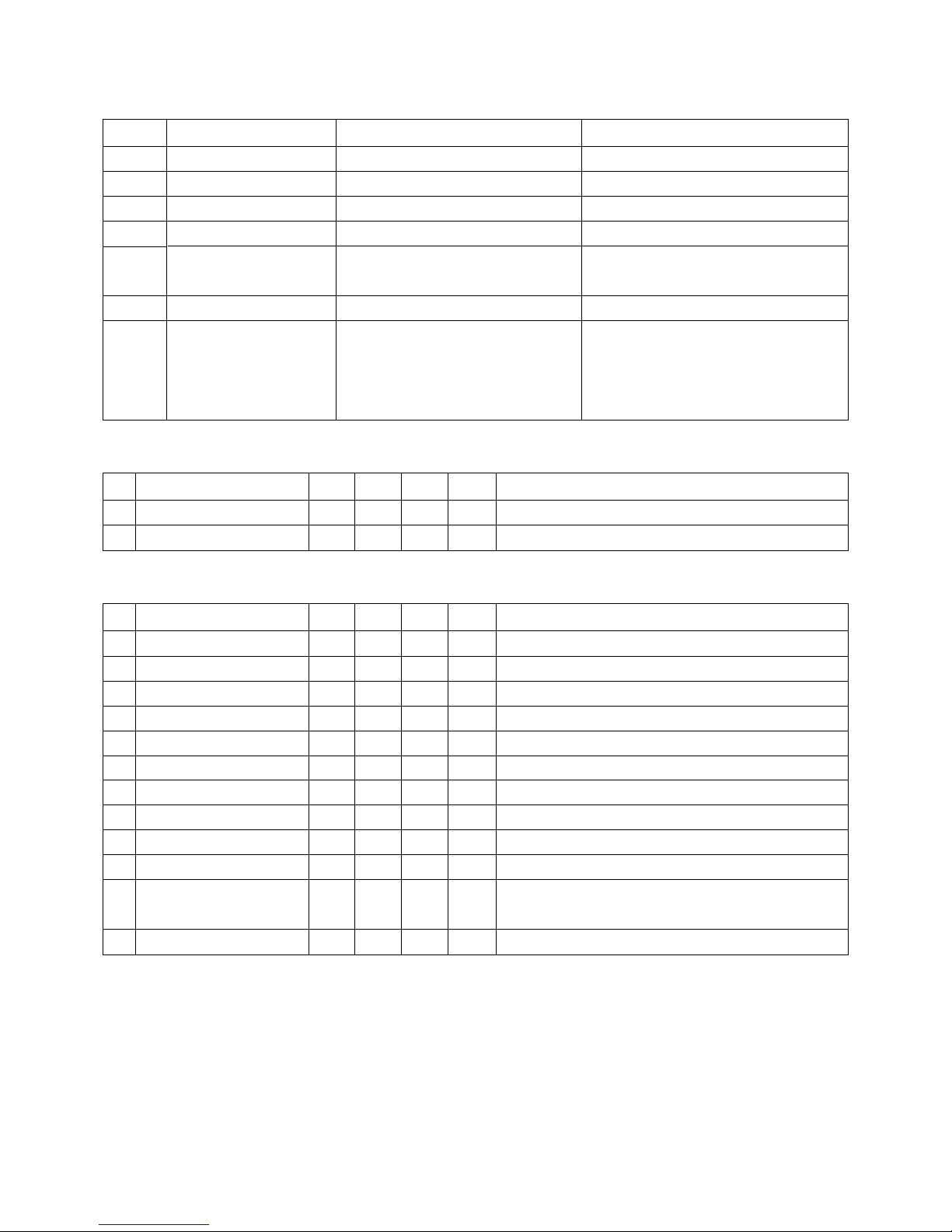
F General Specification
No
Item
Specification
Remark
Video input
applicable system
Input Voltage
Screen Size
Aspect Ratio
PDP Module
Screen Filter
Operating Environment
Storage Environment
1
2
3
4
5
6
7
8
NTSC-M/PAL/SECAM/NTSC4.43(MT,MZ)
MT-42PZ40/41/42/43: 110V -240V 50Hz
MZ-42PZ42/43: 200V -240V 50Hz
42 inch
16:9 (wide)
PDP42WVSN4
Transmissivity: 45%
1)Temp: 0 ~ 40 deg
2)Humidity: 80% under
1)Temp: -20 ~ 60 deg
2)Humidity: 85% under
PDP
LGE
Maker: NBK
O
O
O
O
O
O
16:9, 4:3, Zoom
Noise Reduction(YNR)
Film Mode
Motion detection
Sleep Timer
Orbiter
White Wash
Display Mode
- 9 -
No
Item
Specification
Remark
17
18
19
20
21
22
23
AV,Component 480i
Afterimage Prevention
(left,bottom,right,top,top,right,bottom,left)
Afterimage Remove
480i/p,720p,1080i
: 16:9, 4:3, Zoom
PC(Analog/Digital)
: 4:3, 16:9
F Safety and Regulation
No
Item
Remark
1
2
Power Consumption,Max
Power Consumption,Stand by
300
Min
Typ
UnitMax
350
400
6
W
W
IEC950
F External Interface
No
Item
Remark
1
2
3
4
5
6
7
8
9
10
11
12
Video Input Level
Video Input Frequency Response
Video Input S/N
S Video Input Level(Y)
S Video Input Level(C-BURST)
Audio Input Level
Audio Input Frequency Response
Audio Input S/N
Audio Input Distortion
Audio Input Dynamic Range
Component Video Input Level
(Y,C
B/PB,CR/PR
)
R/G/B Video Input Level
0.9
5
40
0.85
0.143
0.3
0.08
40
2
0.6
0.6
Min
Typ
UnitMax
1
1
0.4
0.7
0.7
1.1
1.15
0.286
0.5
7
2
0.8
0.8
Vpp
MHz
dB
Vpp
Vpp
Vrms
kHz
dB
%
V
Vpp
Vpp
Video Valuation
Video Valuation
Video Valuation
Video Valuation
Video Valuation
NTSC/PAL
Video Valuation, 75 ohm
(480i,480p,720p,1080i)
75ohm
 Loading...