

LG Multi V water mini, ARWN048GA2, ARWN038GA2, ARWN053GA2 Maintenance Manual
Installation, Operation & Maintenance Manual
Variable Refrigerant Flow Water Source Units
3.0, 4.0, and 4.4 Tons
Heat Pump 208-230V, 60Hz, 1 Phase
ARWN038GA2 ARWN048GA2 ARWN053GA2
Note:
PROPRIETARY DATA NOTICE
This document, as well as all reports, illustrations, data, information, and
other materials are the property of LG Electronics U.S.A., Inc., and are
disclosed by LG Electronics U.S.A., Inc., only in confidence.
This document is for design purposes only.
Do not throw away, destroy, or lose this manual.
Please read carefully and store in a safe place for future reference.
Content familiarity required for proper installation.
The instructions included in this manual must be followed to prevent product malfunction, property damage, injury, or death to the user or
other people. Incorrect operation due to ignoring any instructions will cause harm or damage. The level of seriousness is classified by the
symbols described below.
" "
" "
" "
" "
A summary list of safety precautions begins on page 4.
This symbol indicates that the action or lack thereof could possibly cause equipment malfunction or failure.
This symbol indicates that the following action should not be performed.
This symbol indicates that the action or lack thereof could possibly cause death or personal injury.
This symbol indicates that the action or lack thereof could possibly cause property damage.
For more technical materials such as submittals, engineering
databooks, and catalogs, visit www.lg-vrf.com.
For continual product development, LG Electronics U.S.A., Inc., reserves the right to change specifications without notice.
This document, as well as all reports, illustrations, data, information, and other materials are the property of LG Electronics U.S.A., Inc.
©LG Electronics U.S.A., Inc.

TABLE OF CONTENTS
Safety Precautions ...................................................................................................................................................................................................... 4-7
Installation… .............................................................................................................................................................................................................. 4-5
Wiring ………………………………………………………………………………………………………………………………………………………………… 6
Operation …………………………………………………………………………………………………………………………………………………………… 7
Nomenclature ���������������������������������������������������������� 8
Water Source Unit Specications ............................................................................................................................................................................ 9-16
General and Electrical Data .......................................................................................................................................................................................... 9
Dimensions ................................................................................................................................................................................................................. 10
Refrigerant Circuits ................................................................................................................................................................................................ 11-13
Wiring Diagram ........................................................................................................................................................................................................... 14
Accessories ........................................................................................................................................................................................................... 15-16
Installation ��������������������������������������������������������� 17-62
Placement Considerations .......................................................................................................................................................................................... 17
Transporting / Lifting the Water Source Unit ............................................................................................................................................................... 18
Minimum Space Requirements .................................................................................................................................................................................. 19
General Mounting / Anchoring the Water Source Unit ................................................................................................................................................ 20
Refrigerant Piping Installation ............................................................................................................................................................................... 21-40
Computer-assisted Refrigerant Pipe Design .............................................................................................................................................................. 21
System Engineering .............................................................................................................................................................................................. 22-30
Pipe Sizing ............................................................................................................................................................................................................. 31-34
Refrigerant Pipe Connections ................................................................................................................................................................................ 35-37
Insulating the Refrigerant Piping System .............................................................................................................................................................. 38-39
Pressure Testing ........................................................................................................................................................................................................ 40
Product Data
Water Circuit Installation ...................................................................................................................................................................................... 41-117
Water Circuit Design .............................................................................................................................................................................................. 41-42
Piping System Specications ................................................................................................................................................................................ 43-46
Flow Switches and Solenoid Valves ...................................................................................................................................................................... 47-48
Variable Water Flow Control Kit ............................................................................................................................................................................. 49-56
Electrical System Installation ................................................................................................................................................................................. 57-62
General Information .................................................................................................................................................................................................…57
Power Wiring .............................................................................................................................................................................................................. 58
Wiring and Cable Terminations ................................................................................................................................................................................... 59
Communications Cables ........................................................................................................................................................................................ 60-62
Pre-commissioning and Maintenance ................................................................................................................................................................... 63-78
Preparing the Electrical System ................................................................................................................................................................................. 63
Indoor Unit Auto Addressing Auto Addressing ....................................................................................................................................................... 63-66
Group Control ............................................................................................................................................................................................................. 67
Central Control ...................................................................................................................................................................................................... 67-69
Indoor Unit Temperature Sensing Strategy / Air Balance ........................................................................................................................................... 70
Prepare the Refrigerant Piping System ...................................................................................................................................................................... 71
Preparing / Balancing the Water Circuit ...................................................................................................................................................................... 72
Prepare Pre-commissioning Package Documents ..................................................................................................................................................... 73
Initiate a Request ........................................................................................................................................................................................................ 73
Maintaining the Heat Exchanger ................................................................................................................................................................................ 74
General Maintenance Schedule ............................................................................................................................................................................ 75-76
Error Codes .............................................................................................................................................................................................................. 77-82
LG Monitoring View (LGMV) Diagnostic Software ................................................................................................................................................. 77-78
Error Code Tables .................................................................................................................................................................................................. 79-81
Checklists ................................................................................................................................................................................................................. 83-90
LG Multi V Pre-Commissioning Device
Conguration Worksheet ............................................................................................................................................................................................ 83
Installation Checklist .............................................................................................................................................................................................. 84-85
Pre-commissioning Checklist ................................................................................................................................................................................ 86-89
Refrigerant Charge Worksheet ................................................................................................................................................................................... 90
Due to our policy of continuous product innovation, some specifications may change without notification.
©LG Electronics U.S.A., Inc., Englewood Cliffs, NJ. All rights reserved. “LG” is a registered trademark of LG Corp.
3
SAFETY PRECAUTIONS
Note:
The instructions below must be followed to prevent product malfunction, property damage, injury or death to the user or other people.
Incorrect operation due to ignoring any instructions will cause harm or damage. The level of seriousness is classified by the symbols
described below.
" "
This symbol indicates that the action or lack thereof could possibly cause death or personal injury.
" "
" "
This symbol indicates that the action or lack thereof could possibly cause equipment malfunction or failure.
This symbol indicates that the action or lack thereof could possibly cause property damage.
" "
This symbol indicates that the following action should not be performed.
INSTALLATION
Do not install, remove, or re-install the unit by yourself
(customer). Ask the dealer or an authorized technician to
install the unit.
Improper installation by the user may result in water leakage, re,
explosion, electric shock, physical injury or death.
For replacement of an installed unit, always contact an
authorized LG service provider.
There is risk of re, electric shock, explosion, and physical injury or death.
Do not install the water-source units outside.
There is risk of re, electric shock, explosion, and physical injury or death.
Be very careful when transporting the product.
• One person should not carry the product.
• Some products use polypropylene bands for packaging. Do not use
polypropylene bands to lift the unit.
• Suspend the water source unit from the base at specified positions.
Support the water source unit a minimum of four points to avoid slip-
MULTI V Water Mini System Installation Manual
page from rigging apparatus.
The water source unit is shipped with refrigerant and the service valves closed. Do not open service valves on the water
source unit until all non-condensable have been removed
from the piping system and authorization to do so has been
obtained from the commissioning agent.
There is a risk of equipment damage, refrigerant contamination, refrigerant loss, physical injury or death.
The water source unit is shipped with a refrigerant and
service valves closed. Do not run the compressor with the
service valves closed.
There is a risk of equipment damage, explosion, physical injury, or death.
Dispose the packing materials safely.
• Packing materials, such as nails and other metal or wooden parts,
may cause puncture wounds or other injuries.
• Tear apart and throw away plastic packaging bags so that children
may not play with them and risk suffocation and death.
Install the unit considering the potential for strong winds or
earthquakes.
Improper installation may cause the unit to fall over, resulting in physical
injury or death.
If the air conditioner is installed in a small space, take
measures to prevent the refrigerant concentration from
exceeding safety limits in the event of a refrigerant leak.
Consult the latest edition of ASHRAE (American Society of Heating,
Refrigerating, and Air Conditioning Engineers) Standard 15. If the
refrigerant leaks and safety limits are exceeded, it could result in personal
injuries or death from oxygen depletion.
Wear protective gloves when handling equipment. Sharp
edges may cause personal injury.
Do not install the unit on a defective stand.
It may result in an accident that causes product damage or personal injury
or death.
Do not change the settings of the protection devices.
If the pressure switch, thermal switch, or other protection device is
shorted and forced to operate improperly, or parts other than those
specied by LG are used, there is risk of re, electric shock, explosion,
and physical injury or death.
Do not store or use ammable gas or combustibles near the
unit.
There is risk of product failure, re, explosion, and physical injury or death.
4
Due to our policy of continuous product innovation, some specifications may change without notification.
©LG Electronics U.S.A., Inc., Englewood Cliffs, NJ. All rights reserved. “LG” is a registered trademark of LG Corp.
INSTALLATION, CONTINUED
Note:
SAFETY PRECAUTIONS
Replace all control box and panel covers.
If cover panels are not installed securely, dust, water and animals may
enter the water source unit, causing re, electric shock, and physical injury or death.
Install the unit in a safe location where nobody can step on
or fall onto it.
There is risk of unit damage, physical injury or death.
Keep the unit upright during installation.
To avoid vibration or water leakage.
When installing the water source unit in a low-lying area, or
a location that is not level, use a raised concrete pad or concrete blocks to provide a solid, level foundation.
This may prevent water damage and reduce abnormal vibration.
Properly insulate all cold surfaces to prevent “sweating.”
Cold surfaces such as uninsulated piping can generate condensate that
may drip and cause a slippery oor condition and / or water damage to
walls.
Always check for system refrigerant leaks after the unit has
been installed or serviced.
Low refrigerant levels may cause product failure, and exposure to high
concentration levels of refrigerant gas may lead to illness or death.
When installing the unit in a hospital, data center, or similar
electromagentic eld (EMF) sensitive environment, provide
sufcient protection against electrical noise.
Inverter equipment, power generators, high-frequency medical equipment, or radio communication equipment may cause the air conditioner
to operate improperly. The unit may also affect such equipment by creating electrical noise that disturbs medical treatment or image broadcasting.
Do not use the product for special purposes such as preserving foods, works of art, wine coolers, or other precision
air conditioning applications. The equipment is designed to
provide comfort cooling and heating.
There is risk of property damage.
Product Data
Do not make refrigerant substitutions. Use R410A only.
If a different refrigerant is used, or air mixes with original refrigerant, the
unit will malfunction and be damaged.
When connecting refrigerant tubing, remember to allow for
pipe expansion.
Improper piping may cause refrigerant leaks and system malfunction.
Due to our policy of continuous product innovation, some specifications may change without notification.
©LG Electronics U.S.A., Inc., Englewood Cliffs, NJ. All rights reserved. “LG” is a registered trademark of LG Corp.
Do not install the water source unit in a noise sensitive area.
Take appropriate actions at the end of HVAC equipment life
to recover, recycle, reclaim or destroy R410A refrigerant
according to applicable U.S. Environmental Protection
Agency (EPA) rules.
5
Note:
SAFETY PRECAUTIONS
WIRING
The information contained in this manual is intended for use
by an industry-qualied, experienced, certied electrician
familiar with the U.S. National Electric Code (NEC) who is
equipped with the proper tools and test instruments.
Failure to carefully read and follow all instructions in this manual can
result in equipment malfunction, property damage, personal injury or
death.
All electric work must be performed by a licensed electrician
and conform to local building codes or, in the absence of
local codes, with the National Electrical Code, and the
instructions given in this manual.
If the power source capacity is inadequate or the electric work is not
performed properly, it may result in re, electric shock, physical injury or
death.
High voltage electricity is required to operate this system.
Adhere to the NEC code and these instructions when wiring.
Improper connections and inadequate grounding can cause accidental
injury or death.
Always ground the unit following local, state, and NEC codes.
There is risk of re, electric shock, and physical injury or death.
Properly size all circuit breakers or fuses.
There is risk of re, electric shock, explosion, physical injury or death.
Refer to local, state, and federal codes, and use power wires
of sufcient current capacity and rating.
Wires that are too small may generate heat and cause a re.
Secure all eld wiring connections with appropriate wire
strain relief.
Improperly securing wires will create undue stress on equipment power
lugs. Inadequate connections may generate heat, cause a re and physical injury or death.
Properly tighten all power lugs.
Loose wiring may overheat at connection points, causing a re, physical
injury or death.
Do not change the settings of the protection devices.
If the pressure switch, thermal switch, or other protection devices
are bypassed or forced to work improperly, or parts other than those
specied by LG are used, there is risk of re, electric shock, explosion,
and physical injury or death.
Turn the power off at the nearest disconnect before servicing
the equipment.
Electrical shock can cause physical injury or death.
Do not supply power to the unit until all installation and precommissioning tasks are complete and the commissioning
agent indicates it is safe to do so.
MULTI V Water Mini System Installation Manual
6
Due to our policy of continuous product innovation, some specifications may change without notification.
©LG Electronics U.S.A., Inc., Englewood Cliffs, NJ. All rights reserved. “LG” is a registered trademark of LG Corp.
OPERATION
SAFETY PRECAUTIONS
Do not allow water, dirt, or animals to enter the unit.
There is risk of unit failure, re, electric shock, physical injury or death.
Do not provide power to or operate the unit if it is ooded or
submerged.
There is risk of re, electric shock, physical injury or death.
Use a dedicated outlet for this product.
There is risk of re, electric shock, physical injury or death.
Do not operate the disconnect switch with wet hands.
There is risk of re, electric shock, physical injury or death.
Periodically verify the equipment mounts have not
deteriorated.
If the base collapses, the unit could fall and cause property damage,
product failure, physical injury or death.
Do not touch the refrigerant piping during or after operation.
It can cause burns or frostbite.
Do not operate the unit with the panel(s) or protective
cover(s) removed; keep ngers and clothing away from
moving parts.
The rotating, hot, cold, and high-voltage parts of the unit can cause
physical injury or death.
If gas leaks out, ventilate the area before operating the unit.
Leaking gas may cause re, electric shock, explosion, physical injury or
death if the water source unit is mounted in an enclosed, low-lying, or
poorly ventilated area and the system develops a refrigerant leak.
To avoid physical injury, use caution when cleaning or
servicing the air conditioner.
The water source unit is shipped with refrigerant and the service valves closed. Do not open service valves on the water
source unit until all non-condensable have been removed
from the piping system and authorization to do so has been
obtained from the commissioning agent.
There is a risk of equipment damage, refrigerant contamination, refrigerant loss, physical injury or death.
The water source unit is shipped with a refrigerant and
service valves closed. Do not run the compressor with the
service valves closed.
There is a risk of equipment damage, explosion, physical injury, or death.
Product Data
Do not use this equipment in mission critical or specialpurpose applications such as preserving foods, works of art,
wine coolers or refrigeration. The equipment is designed to
provide comfort cooling and heating.
Oil, steam, sulfuric smoke, etc., can signicantly reduce the performance of the unit, or damage its parts.
Do not turn off the main power switch after operation has
been stopped.
Wait at least ve (5) minutes before turning off the main power
switch, otherwise it may result in product malfunction.
Due to our policy of continuous product innovation, some specifications may change without notification.
©LG Electronics U.S.A., Inc., Englewood Cliffs, NJ. All rights reserved. “LG” is a registered trademark of LG Corp.
Provide power to the compressor crankcase heaters at least
six (6) hours before operation begins.
Starting operation with a cold compressor sump(s) may result in severe
bearing damage to the compressor(s). Keep the power switch on during
the operational season.
Clean up the site after servicing is nished, and check that
no metal scraps, screws, or bits of wiring have been left
inside or surrounding the unit.
7
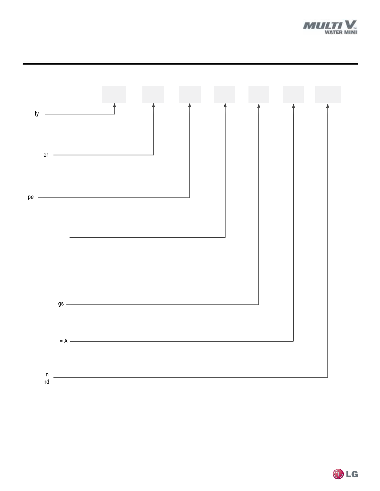
UNIT NOMENCLATURE
Water Mini Unit
Water Source Units (WSU)
Family
AR = Multi V (Refrigerant R410A)
Condenser
W = Water Source
Type
N = Heat Pump
Nominal Capacity
Nominal cooling capacity in Btu/h
038 = 38,200
048 = 47,800
053 = 52,900
AR W N
038 G A
2
Electrical Ratings
G = 208–230V / 60Hz / 1Ø
MULTI V Water Mini System Installation Manual
Basic Function = A
Generation
2 = Second
8
Due to our policy of continuous product innovation, some specifications may change without notification.
©LG Electronics U.S.A., Inc., Englewood Cliffs, NJ. All rights reserved. “LG” is a registered trademark of LG Corp.
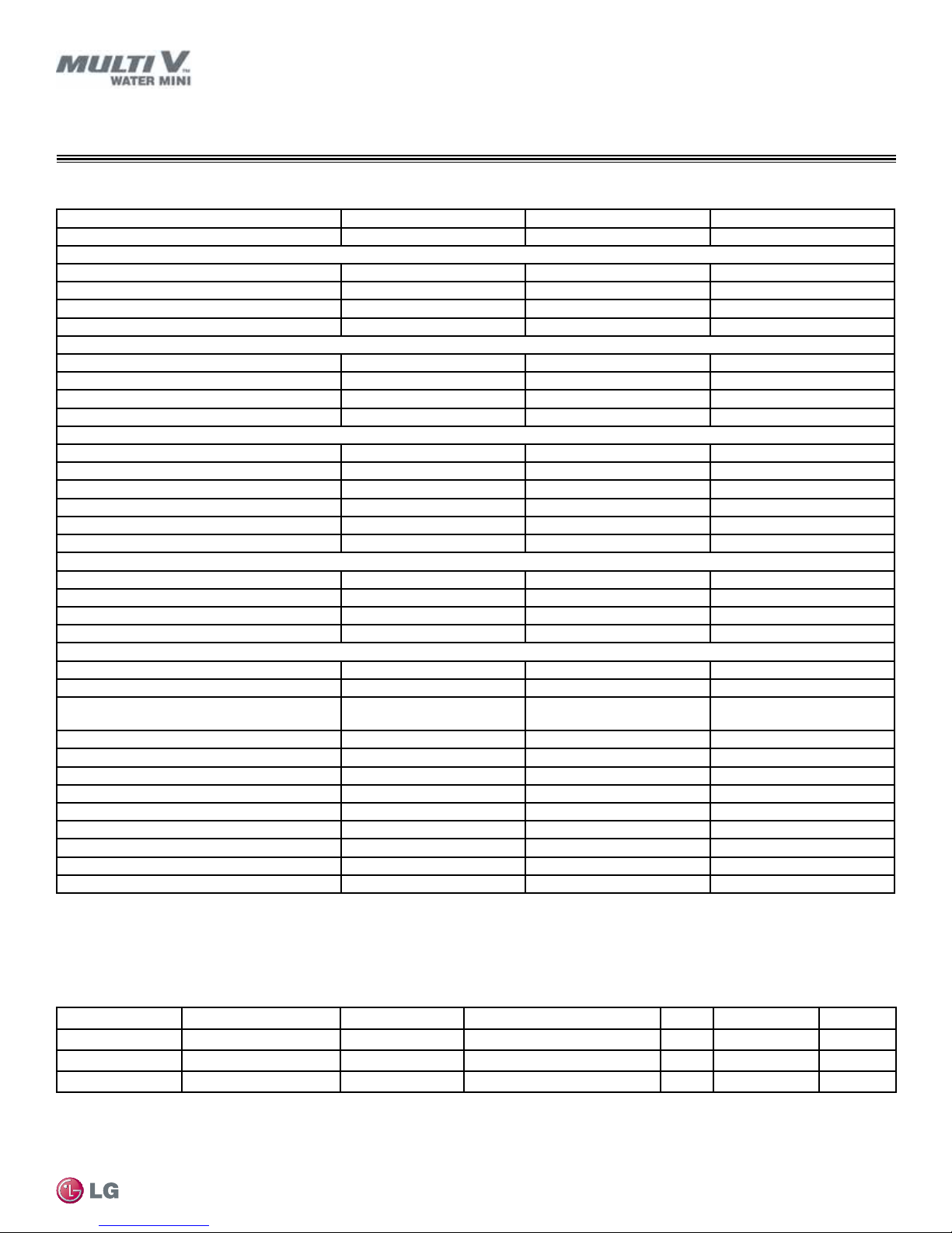
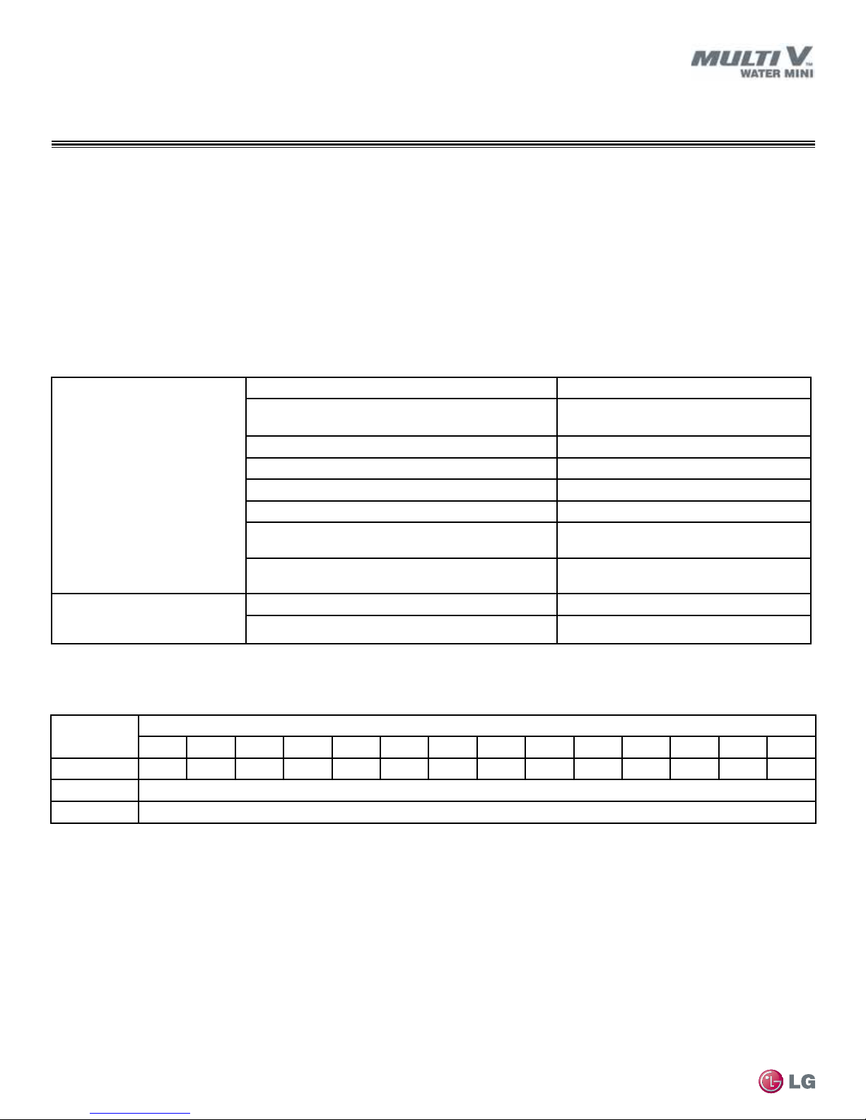
GENERAL DATA
Water Mini Unit Specications and Electrical Data
Table 1: General Data—ARWN038GA2, ARWN048GA2, ARWN053GA2 Water Mini Units.
3.0 Ton 4.0 Ton 4.4 Ton
Model Number ARWN038GA2 ARWN048GA2 ARWN053GA2
Nominal Capacity / Input Power
Cooling Capacity (Btu/h)
Cooling Input Power (kW) 2.1 2.7 3.2
Heating Capacity (Btu/h)
Heating Input Power (kW) 2.2 2.9 3.5
Compressor
Type Inverter Rotary Inverter Rotary Inverter Rotary
Power Supply (volt/hz/phase)
MCA (A) 26 26.5 27
MOP (A) 45 45 45
System Data
Sound Pressure (dBA)
Heat Rejected to Equipment Room (Btu/h) 512 512 512
Net Weight (lbs) 168 168 168
Shipping Weight (lbs) 181 181 181
Dimensions (W x H x D) 20-5/8 x 42-1/2 x 13-1/8 20-5/8 x 42-1/2 x 13-1/8 20-5/8 x 42-1/2 x 13-1/8
Max. Qty Indoor Units 6 8 9
Refrigerant Piping Connections
Vapor Line OD (in) 3/4 Braze 3/4 Braze 3/4 Braze
Liquid Line OD (in) 3/8 Braze 3/8 Braze 3/8 Braze
Expansion Device Electronically Controlled (EEV) Electronically Controlled (EEV) Electronically Controlled (EEV)
Factory Refrigerant Charge (R410A [lbs]) 2.2 2.2 2.2
Water Side
Heat Exchanger Stainless Steel Plate Stainless Steel Plate Stainless Steel Plate
Water Volume in Heat Exchanger (gal.)
Water Inlet/Outlet Connection
Size (in)
Nominal Flow Rate Total (GPM)
Range of Flow (GPM)
Entering water temp. range (°F)– Cooling 50-113 50-113 50-113
Entering water temp. range (°F)– Heating 23-113 23-113 23-113
Total Heat of Rejection (Btu/h) 44,330 55,550 56,640
Total Heat of Absorption (Btu/h) 35,087 44,697 49,448
Pressure Drop (ft) 4.7 6.9 9.5
Maximum Water Pressure (psi) 640 640 640
5
ΔT (°F)
1
Cooling – Indoor 80°F DB/66°F WB, Water Temp. Entering 86°F;
Heating- Indoor 68°F DB, Water Temp. Entering 68°F.
2
Voltage tolerance is ±10%.
3
Sound pressure levels as tested in anechoic chamber under ISO
Standard 3745.
1
1
2
3
4
38,200 47,800 52,900
42,600 54,600 61,400
208-230 / 60 / 1 208-230 / 60 / 1 208-230 / 60 / 1
52 53 54
0.2 0.2 0.2
1-1/4 FPT 1-1/4 FPT 1-1/4 FPT
10.6 13.2 15.9
5.5-13.3 6.9-16.5 8.3-19.9
4
Refer to the Refrigerant Piping Section of this manual for correct
line sizing. Contractor MUST use LG manufactured Y-branch fittings
only. Designer must verify refrigerant piping design configuration
using LG’s computerized refrigerant piping CAD/calculation (LATS)
Software to layout and design the refrigerant piping system.
8 8 7
5
Calculated from ∆T = Total Heat of Rejection / (Nominal flow rate
x 500).
Product Data
Table 2: 208-230V, 60Hz, 1-Phase Water Mini Unit Electrical Characteristics.
Nominal Tons Unit Model No. Compressor Qty. Compressor Motor RLA MSC MCA MOP
3.0 ARWN038GA2 1 20.8 - 26 45
4.0 ARWN048GA2 1 21.2 - 26.5 45
4.4 ARWN053GA2 1 21.6 - 27 45
MCA = Minimum Circuit Ampacity.
MOP = Maximum Overcurrent Protection is calculated as follows: (Largest motor FLA x 2.25) + (Sum of
other motor FLA) rounded down to the nearest standard fuse size.
Allowable voltage range is between 208–230 volts only (tolerance is 10%).
Maximum allowable voltage imbalance is 2%.
Due to our policy of continuous product innovation, some specifications may change without notification.
©LG Electronics U.S.A., Inc., Englewood Cliffs, NJ. All rights reserved. “LG” is a registered trademark of LG Corp.
Power wiring to be sized to meet local or NEC codes.
Measurements are taken with no attenuation and units operating at full load nominal operating
condition.
Measurements are taken 4.9 feet above the finished floor and a distance of 3.3 feet from the face of the
fan discharge.
9
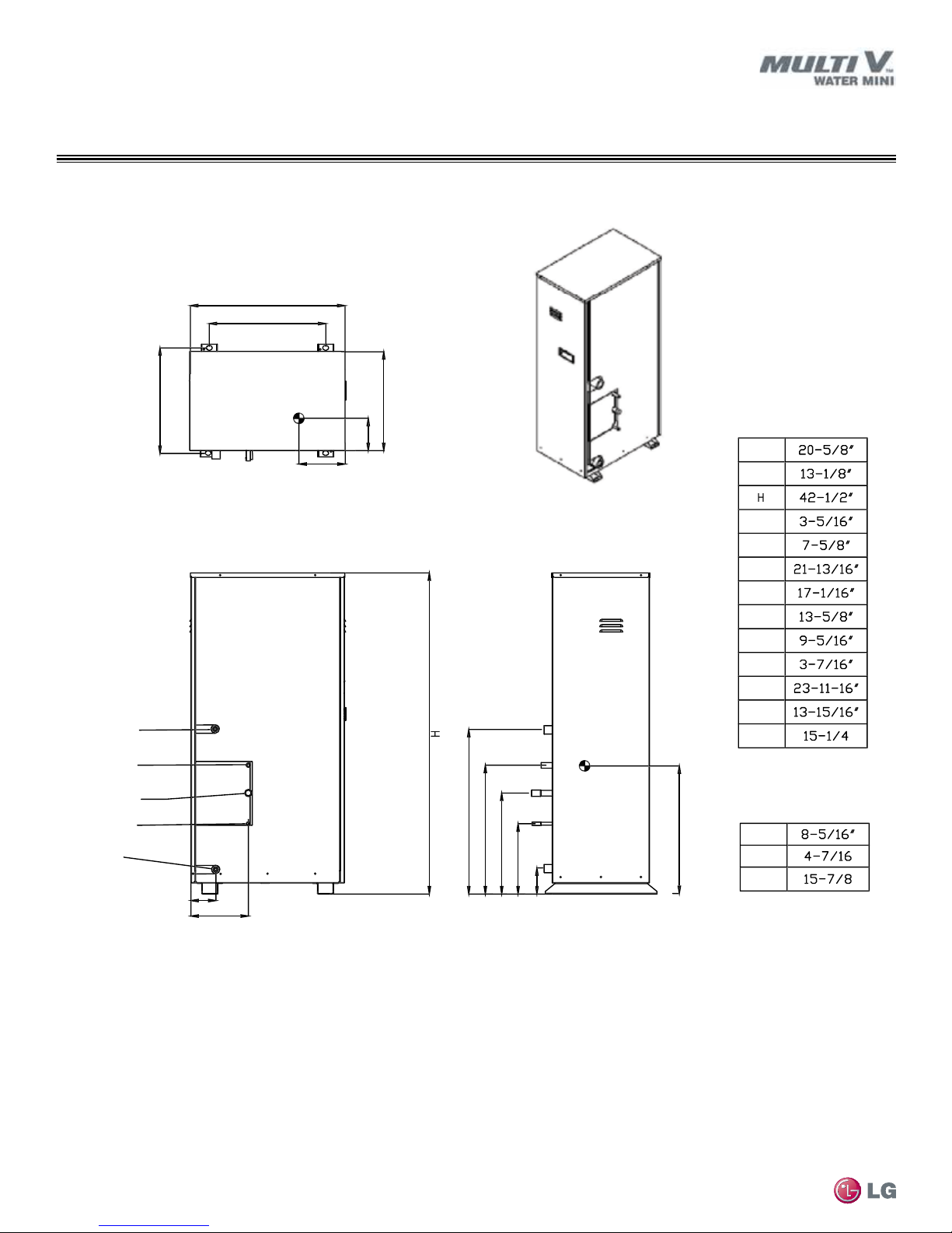
DIMENSIONS
S
6
3
2
V
Water Outlet
Wate
et
2
3
5
6
8
1
X
Y
ARWN038GA2, ARWN048GA2, ARWN053GA2
Figure 1: ARWN038GA2, ARWN048GA2, ARWN053GA2 Dimensions.
1
Top View
apped Line
apor Line
Liquid Line
MULTI V Water Mini System Installation Manual
r Inl
L
ront View
Isometric
L
L
L
L
L
L7
L
M
L
L
Z
ide View
10
Due to our policy of continuous product innovation, some specifications may change without notification.
©LG Electronics U.S.A., Inc., Englewood Cliffs, NJ. All rights reserved. “LG” is a registered trademark of LG Corp.
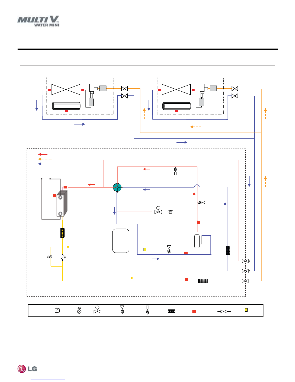
REFRIGERANT FLOW DIAGRAMS
EEV
Filter
EEV
Filter
Indoor HEX
Indoor HEX
Fan
Indoor Unit
Indoor Unit
Fan
Liquid
Gas
HEX
Temp
Liquid
Temp
Suction
Temp
Hot Gas
Bypass
Valve
4 Way
Valve
Main
EEV
Low
Pressure
Sensor
Accumu
lator
Inv.
Comp.
High
Pressure
Switch
Discharge
Temp
High
Pressure
Sensor
Check
Valve
Solenoid
Valve
Strainer
Thermistor
Remark
High
Pressure
Switch
S
High
Water In Water Out
Plate
Heat Exchanger
Pressure
Sensor
SVC
Valve
Fusible
Plug
EEV
Fusible
Plug
High Temperature High Pressure Gas
High Temperature High Pressure Liquid
Low Temperature Low Pressure Gas
S
ARWN038GA2, ARWN048GA2, ARWN053GA2
Figure 2: ARWN038GA2, ARWN048GA2, ARWN053GA2—Cooling Mode.
Cooling Mode
Product Data
Due to our policy of continuous product innovation, some specifications may change without notification.
©LG Electronics U.S.A., Inc., Englewood Cliffs, NJ. All rights reserved. “LG” is a registered trademark of LG Corp.
11

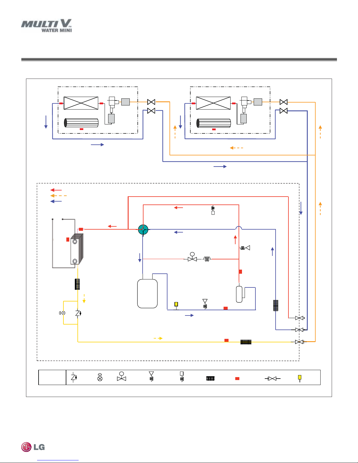
REFRIGERANT FLOW DIAGRAMS
Heating Mode
ARWN038GA2, ARWN048GA2, ARWN053GA2
Figure 3: ARWN038GA2, ARWN048GA2, ARWN053GA2—Heating Mode.
Indoor HEX
Fan
High Temperature High Pressure Gas
High Temperature High Pressure Liquid
Low Te mperature Low Pressure Gas
Water In Water Out
HEX
Temp
Plate
Heat Exchanger
EE V
Filter
Indoor Unit
4 Way
Valve
Hot Gas
Bypass
Valve
S
Indoor HEX
Fan
High
Pressure
Switch
EEV
Filter
Indoor Unit
High
Pressure
Sensor
Main
EEV
MULTI V Water Mini System Installation Manual
S
Remark
Check
Valve
EEV
Solenoid
Valve
Accumu
lator
Pressure
Sensor
Fusible
Plug
Low
Pressure
Sensor
High
Pressure
Switch
Inv.
Comp.
Suction
Temp
Liquid
Temp
Strainer
Discharge
Temp
Thermistor
SVC
Valve
High
Gas
Liquid
Fusible
Plug
12
Due to our policy of continuous product innovation, some specifications may change without notification.
©LG Electronics U.S.A., Inc., Englewood Cliffs, NJ. All rights reserved. “LG” is a registered trademark of LG Corp.
REFRIGERANT FLOW DIAGRAMS
Filter Filter
Indoor Unit
Indoor Unit
Fan
Fan
Indoor HEX Indoor HEXEEV EEV
Liquid
Gas
HEX
Temp
Liquid
Temp
Suction
Temp
Hot Gas
Bypass
Valve
4 Way
Valve
Main
EEV
Low
Pressure
Sensor
Accumu
lator
Inv.
Comp.
High
Pressure
Switch
Discharge
Temp
High
Pressure
Sensor
High
Water In Water Out
Plate
Heat Exchanger
Fusible
Plug
Check
Valve
Solenoid
Valve
Strainer
Thermistor
Remark
High
Pressure
Switch
Pressure
Sensor
SVC
Valve
Fusible
Plug
EEV
High Temperature High Pressure Gas
High Temperature High Pressure Liquid
Low Temperature Low Pressure Gas
S
S
ARWN038GA2, ARWN048GA2, ARWN053GA2
Figure 4: ARWN038GA2, ARWN048GA2, ARWN053GA2—Oil Return.
Oil Return Operation
Product Data
Due to our policy of continuous product innovation, some specifications may change without notification.
©LG Electronics U.S.A., Inc., Englewood Cliffs, NJ. All rights reserved. “LG” is a registered trademark of LG Corp.
13
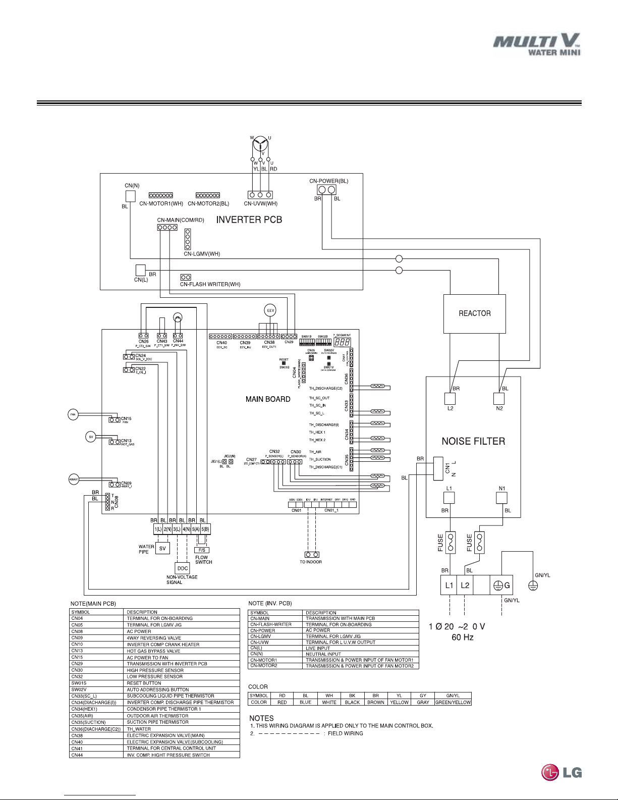
WIRING DIAGRAM
83
ARWN038GA2, ARWN048GA2, ARWN053GA2
Figure 5: ARWN038GA2, ARWN048GA2, ARWN053GA2 Wiring Diagram.
MULTI V Water Mini System Installation Manual
14
Due to our policy of continuous product innovation, some specifications may change without notification.
©LG Electronics U.S.A., Inc., Englewood Cliffs, NJ. All rights reserved. “LG” is a registered trademark of LG Corp.

Vapor pipe Liquid pipe
Unit: Inch
Models
ARBLN01621
ARBLN03321
16-1/4
15-3//8
I.D. 3/4
I.D. 3/4
I.D. 3/4
I.D. 3/4
O.D. 5/8
I.D. 1/2
I.D. 5/8
I.D. 5/8
I.D. 5/8
I.D. 1/2
I.D. 1/2
I.D. 1/2
I.D. 1/2
I.D. 1/2
I.D. 1/2
I.D. 1/2
I.D. 1/2
11-1/2
11-1/16
11-1/2
11-1/16
2-15/16
2-15/16
2-15/16
2-3/4
2-3/4
2-3/4
I.D. 5/8
I.D. 5/8
I.D. 1
I.D. 1
O.D. 1
3-3/16
4-3/8
13-1/16
12-5/8
3-5/16
1
2
3
3
O.D. 3/4
O.D. 3/4
1 2
I.D. 7/8
I.D. 7/8
I.D. 7/8
I.D. 1/4
I.D. 1/4
I.D. 1/4
I.D. 1/4
I.D. 1/4
1
1
1
1
I.D. 1-1/8
I.D. 3/8
I.D. 3/8
I.D. 3/8
I.D. 3/8
I.D. 3/8
I.D. 3/8
O.D. 3/8
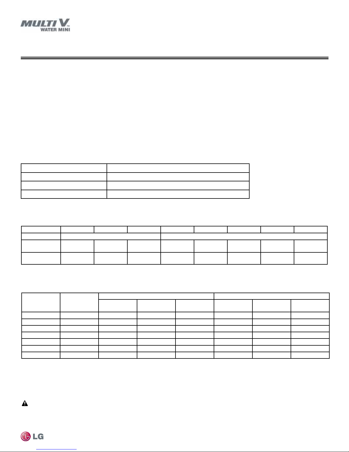
Table 4: Required Accessories.
Required Accessories Model No.
Y-branches
(for indoor unit connection)
Headers
(for indoor unit connection)
Four (4) branch Seven (7) branch Ten (10) branch
ARBL054 ARBL057 ARBL1010
ARBL104 ARBL107 ARBL2010
Y-branches (for indoor unit connection)
Table 3: Y-branch Table.
ACCESSORIES
ARBLN01621
ARBLN03321
Due to our policy of continuous product innovation, some specifications may change without notification.
©LG Electronics U.S.A., Inc., Englewood Cliffs, NJ. All rights reserved. “LG” is a registered trademark of LG Corp.
Product Data
15
Unit: Inch
4 branch
ARBL054
7 branch
ARBL057
4 branch
ARBL104
7 branch
ARBL107
10 branch
ARBL1010
10 branch
ARBL2010
Models Vapor pipe Liquid pipe
14-3/16
21-1/4
21-1/4
4-3/4
I.D. 5/8
I.D. 1/2
I.D. 1/2
I.D. 5/8
I.D. 5/8
I.D. 3/4
4-3/4
14-3/16
I.D. 3/8
I.D. 3/8
I.D. 1/4
I.D. 1/4
I.D. 3/8
I.D. 1/2
5-15/16
5-15/16
5-15/16
5-15/16
5-15/16
15-3/4
6-5/16
I.D. 5/8
I.D. 1/2
I.D. 3/4
I.D. 5/8
I.D 7/8
I.D. 1-1/8
I.D. 1
4-3/4
4-3/4
4-3/4
4-3/4
4-3/4
4-3/4
4-3/4
4-3/4
4-3/4
4-3/4
I.D. 5/8
I.D. 1/2
I.D. 5/8
I.D. 1/2
I.D. 5/8
I.D. 3/4
4-3/4
I.D. 1/4
I.D. 3/8
I.D. 3/8
I.D. 1/2
6-5/16
22-7/8
I.D. 3/4
I.D. 5/8
ID15.88(5/8)
ID12.7(1/2)
I.D. 5/8
I.D. 1/2
I.D. 7/8
I.D. 1-1/8
I.D. 1
27-9/16
4-3/4
I.D. 1/4
I.D. 3/8
I.D. 3/8
I.D. 1/4
I.D. 3/8I.D. 1/2
I.D. 5/8
I.D. 1/2
4-3/4
28-3/8
I.D. 1/4
I.D. 3/8
I.D. 3/8
I.D. 1/4
I.D. 1/2
I.D. 3/8
4-1/4
21-1/2
27-9/16
I.D. 1/4
I.D. 3/8
I.D. 3/4
I.D. 5/8
I.D. 3/8
I.D. 1/4
4-3/4
4-3/4
6-5/16
29-7/8
I.D. 3/4
I.D. 5/8
I.D. 7/8
I.D. 1-1/8
I.D. 1
7-3/16
30-9/16
I.D. 3/4
I.D. 5/8
I.D. 5/8
I.D. 1/2
I.D. 1-1/8
I.D. 1-1/4
I.D. 1-3/8
5-15/16
5-15/16
5-15/16
5-15/16
5-15/16
5-15/16
5-15/16
4-3/4
4-3/4
14-3/16
I.D. 3/8
I.D. 3/8
I.D. 1/4
I.D. 1/4
I.D. 3/8
I.D. 1/2
ACCESSORIES
Headers (for indoor unit connection)
Table 5: Header Table.
MULTI V Water Mini System Installation Manual
16
Due to our policy of continuous product innovation, some specifications may change without notification.
©LG Electronics U.S.A., Inc., Englewood Cliffs, NJ. All rights reserved. “LG” is a registered trademark of LG Corp.
INSTALLATION
Note:
Placement Considerations
Selecting the Best Location
The water source unit must be installed indoors in a mechanical room. The mechanical room must be designed such that equipment vibration
or noise does not affect surrounding rooms, and is properly ventilated or conditioned to maintain an acceptable ambient temperature range
between 32°F and 104°F. Mechanical room temperature is required to be maintained between 32°F and 104°F. The water source unit will
reject heat to the mechanical room. See the “General Data” on page 9 for the amount of heat rejected to the equipment room.
• The water source unit must also be located where the refrigerant pipe system is designed within the piping limitations set forth in the Water
Mini Engineering Manual. Location of the water source unit should be strategically located in the building to minimize refrigerant piping
materials, labor, and refrigerant.
• The underlying structure or foundation must be designed per local codes and support the weight of the unit. Units can be stacked above
each other as long as each water source unit is independently supported. Minimum clearances must be maintained either per recommendations shown in Figures 2 and 3 or local codes, whichever is greater. Include enough space in the installation area for service access (refer
to the installation space requirements).
• The mechanical room floor should be made waterproof. Periodic flushing of the water heat exchanger will be required, and a floor drain
installed nearby the equipment will help facilitate this maintenance.
Installation Instructions
• The water-source unit should be installed with a closed-loop water system. If an open-loop system is used, it is recommended that an
intermediate heat exchanger be installed.
• When piping, towers, or other system components that contain water and are exposed to ambient air temperatures below 32°F, an antifreeze solution must be used. Frozen water will damage the plate heat exchanger. A typical antifreeze solution consists of a proper mixture
of ethylene glycol, propylene glycol, or methanol mixed with water. The designer should also consider the use of a supplemental boiler /
heater to maintain minimum temperatures.
Avoid exposing the water-source unit to oil, steam, combustible gases, acidic solutions or sprays, carbon ber, sulfur, or other corrosive gases.
Avoid exposure to electromagnetic waves from EMF radiating machinery such as generators, MRI equipment, or other equipment that emits
electromagnetic energy. The control system may be affected by electromagnetic energy, which may result in abnormal system operation. Also,
the inverter components in the water source units may generate electromagnetic noise, therefore, ensure the water-source unit is placed at an
acceptable distance from computer, audio, and other sensitive electronic equipment. Route power wiring and communications cables in separate conduits.
Due to our policy of continuous product innovation, some specifications may change without notification.
©LG Electronics U.S.A., Inc., Englewood Cliffs, NJ. All rights reserved. “LG” is a registered trademark of LG Corp.
17
INSTALLATION
≤40°
Mounting Rail
A:
B:
A
A
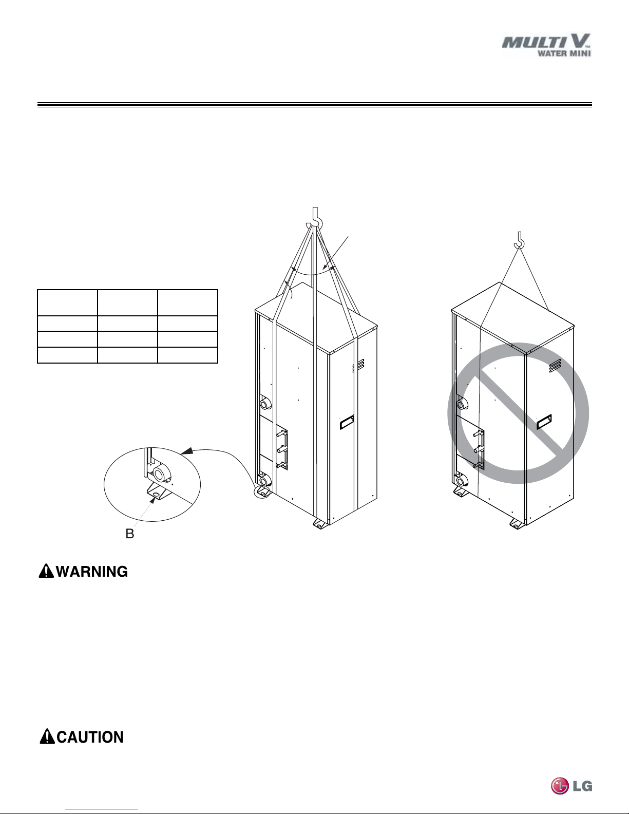
Transporting / Lifting the Water Source Unit
Transporting / Lifting
• When lifting the unit, use lifting straps and place around the unit as shown below.
• Always lift the unit using properly sized lifting straps rated to carry the unit weight.
• Ensure the straps are long enough to maintain a maximum of a 40° angle as shown at “A”.
Figure 6: Transporting the Water Source Unit.
Table 6: Water Mini Net and Shipping Weights.
Capacity
(ton)
3.0 168 181
4.0 168 181
4.5 168 181
Net Weight
(lbs.)
Shipping
Weight (lbs.)
MULTI V Water Mini System Installation Manual
• One person should not carry the product.
• Some products include polypropylene bands around the unit for packaging. Do not use polypropylene bands to lift the unit.
• Tear apart and throw away plastic packaging bags so that children may not play with them and risk suffocation and death.
• Lift the water source unit from the base at specified locations. Support the water source unit at a minimum of six (6) points to avoid
slippage from the rigging apparatus.
• Do not drop the unit when carrying it with a forklift.
• Use a minimum of three (3) lifting straps.
• Place a protective cloth or other soft material at the locations where the casing comes in contact with the lifting straps to prevent
damage to painted surfaces.
• Always know where the center of gravity of the water source unit is before lifting. Hoist the unit with the center of gravity centered
among the lifting straps.
Caution when using forklift to transport an unpackaged unit. Consider the unit’s center of gravity when lifting. Protect the painted surfaces as
necessary to prevent damage to the unit nish.
18
Due to our policy of continuous product innovation, some specifications may change without notification.
©LG Electronics U.S.A., Inc., Englewood Cliffs, NJ. All rights reserved. “LG” is a registered trademark of LG Corp.
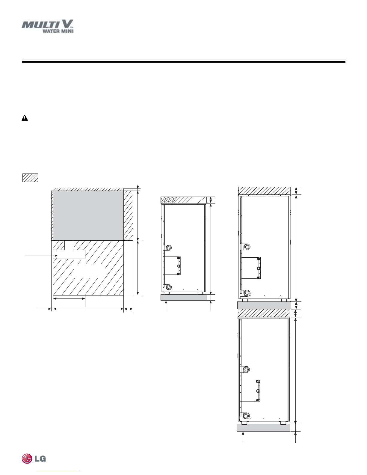
: Required Minimum Service Area
7/8
4
7-1/2
20-1/2
Field-Provided H-Beam Support
Unit: Inch
23-5/8
15
42-1/2
4
4
7/8
Front View
Water pipe
installation
space
Plan View
Exterior of
Water Source
Unit
Service area
(Front)
INSTALLATION
Field-Provided H-Beam Support or Floor
Unit: Inch
4
Note:
Minimum Space Requirements
Installation Space
When installing the water-source unit, provide service requirements as illustrated. If local code requires additional clearance area, comply
with local codes.
Job site conditions may require routing utilities—including the refrigerant piping and electrical wiring—under the unit base. If job site conditions
warrant, consider adding mounting rails under the unit.
Figure 7: Required Minimum Space for Water Mini Unit Installation.
Figure 8: Stacked Water Source Units.
Installation Instructions
4
42-1/2
Field-Provided H-Beam Support
4
42-1/2
Due to our policy of continuous product innovation, some specifications may change without notification.
©LG Electronics U.S.A., Inc., Englewood Cliffs, NJ. All rights reserved. “LG” is a registered trademark of LG Corp.
4
19

Note:
Unit: Inch
INSTALLATION
General Mounting / Anchoring the Water Source Unit
General Mounting
Securely attach the water source unit to a concrete pad, base rails, or other mounting platform that is anchored to the building structure.
Avoid placing the unit in a low lying area where water may accumulate. Refer to dimensional drawing in the “Product Data” section on page
10, and follow the applicable local code for clearance, mounting, anchor, and vibration attenuation requirements.
• When building a base support for the water source unit, ensure that the floor surface / location has enough strength to support the
weight of the unit, and enough space for pipes and wiring.
• Install the water source unit to a base and in a manner approved by the structural engineer to minimize damage to the unit in the event
of an earthquake. Any deficiency in installation may cause unit to fall, resulting in physical injury or death.
Anchoring the Water Source Unit
Figure 9: Location of the Anchor Bolts.
15-1/4
Front
Plan View
• Securely fasten all four (4) corners to the
MULTI V Water Mini System Installation Manual
supporting base.
• If not otherwise directed by the structural
engineer or local codes, Use a 7/16 inch or
1/2 inch diameter J-bolt. Use a hexagon nut
with a spring washer.
• Include anti-vibration material chosen by the
acoustics engineer.
• Include enough space for refrigerant piping
and electrical wiring when installing through
the bottom of the unit.
• Use an H-beam, concrete support, or other
acceptable support structure designed by a
structural engineer.
Figure 10: Close up of Anchor Bolts.
Unit Mounting
H-Beam
4
Foot
3
13-15/16
Location of the
anchor bolts
Spring Washer
Nut
Side View
Anti-vibration
Material
Unit: Inch
Concrete
Base
Three Threads
Four Bolts
Required
3
8
8
All referenced materials are to be eld-supplied. Images are not to scale, are for reference only, and are not intended to be used for design
purposes.
20
Due to our policy of continuous product innovation, some specifications may change without notification.
©LG Electronics U.S.A., Inc., Englewood Cliffs, NJ. All rights reserved. “LG” is a registered trademark of LG Corp.
REFRIGERANT PIPING DESIGN
Note:
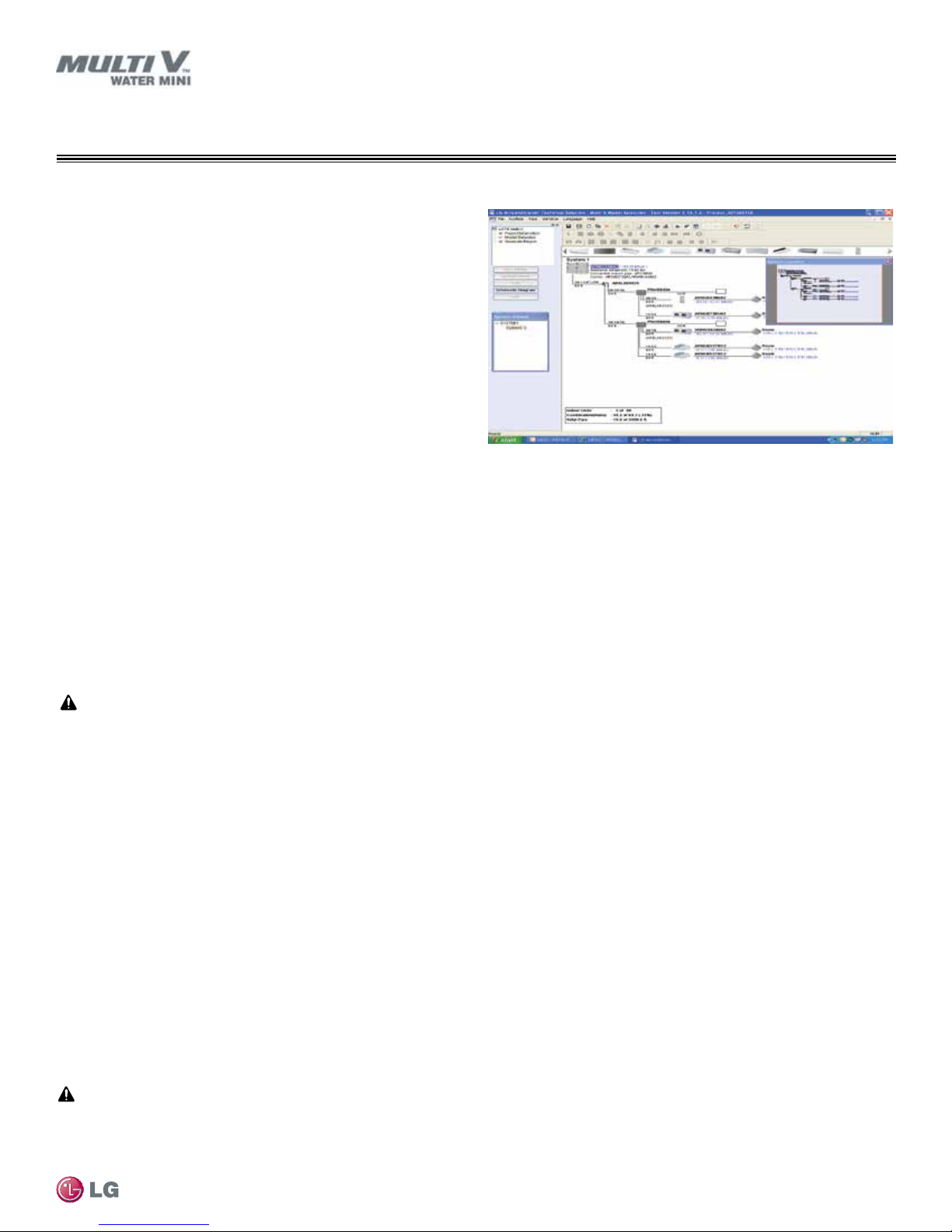
Computer-assisted Refrigerant Pipe Design
LATS Multi V Piping Design Software
The proper design and installation of the refrigerant piping system is
a critical element of the Multi V system. Multi V Water Mini requires
two pipes between system components – a liquid line and a vapor
line. A properly designed refrigerant piping system ensures that
refrigerant is delivered to the evaporator coil’s electronic expansion valve (EEV) in a pure liquid state free of gas bubbles. A proper
design also ensures a sufficient refrigerant gas flow rate in the vapor
line that eliminates the possibility of refrigeration oil from collecting in
the vapor lines.
Figure 11: LATS Pipe System Design Tool in Tree Mode.
Refrigerant Piping Quality Assurance
LG’s LATS Multi V software makes designing the refrigerant system
easy. LATS Multi V is a Windows®-based application that assists the
engineer in the design of the refrigeration distribution pipe system, verifies the design complies with pipe design limitations, applies capacity correction factors, and calculates the system refrigerant charge. The piping system can be entered manually into LATS from a one-line
pipe diagram. To ensure that the refrigerant piping design meets LG’s quality standards, a LATS refrigerant piping design must be
provided with every Multi V Water Mini order. Following the installation, if any changes or variations to the design were necessary,
a new “as-built” LATS piping design software report must be created and provided to LG prior to system commissioning.
Systems that are close to the standard application limits may be converted into a conditional application by field changes to pipe equivalent
lengths. User should always check the LATS report actual pipe layout versus pipe limits. The user may want to increase pipe lengths when
design conditions are approaching the Standard Application Piping Rule limits to force the LATS program to engineer the system using the
“Conditional Application Pipe Rules,” which will increase the diameter of the main and a few branch segments to minimize the possibility of
required pipe changes due to field installation variations.
Refrigerant Piping
Note:
Any eld changes, such as re-routing, shortening or lengthening a pipe segment, adding or eliminating elbows and/or ttings, re-sizing,
adding, or eliminating indoor units, changing the mounting height or moving the location of a device or tting during installation
should be done with caution and ALWAYS VERIFIED in LATS MULTI V SOFTWARE BEFORE supplies are purchased or installed.
Doing so may lead to a more protable installation, reduce the potential for rework, and will reduce the potential for multiple visits
to the job site to complete the system commissioning.
Adjusting LATS Multi V Output for Altitude
When a system is installed at elevations significantly above sea level, the designer must also consider the impact air density has on the
capacity of the indoor and water source units. LATS does not de-rate indoor unit capacity for high altitude applications. Locally accepted
altitude correction factors must be applied to indoor unit capacities.
Creating a Balanced Piping System
Unlike designing duct-work or chilled and hot water pipe systems where balancing dampers, ball valves, orifices, circuit setters, or other
flow control devices can be installed to modify or balance the flow of cooling medium, these cannot be used in a VRF system. Therefore,
variable refrigerant flow systems have to be designed to be “self balanced.” Balanced liquid refrigerant distribution is solely dependent on
the designer choosing the correct pipe size for each segment. Pipe sizing considerations include pipe length, pipe segment pressure drop
relative to other pipe segments in the system, type and quantity of elbows, bends present, fitting installation orientation, and end use device
elevation differences.
It is imperative the designer avoids creating excessive pressure drop. When liquid refrigerant is subjected to excessive pressure drop, liquid
refrigerant will change state and “ash” to vapor. Vapor present in a stream of liquid refrigerant before reaching the electronic expansion
valve (EEV) results in a loss of system control and causes damage to the valve. The pipe system must be designed in a manner that avoids
the creation of unwanted vapor.
Due to our policy of continuous product innovation, some specifications may change without notification.
©LG Electronics U.S.A., Inc., Englewood Cliffs, NJ. All rights reserved. “LG” is a registered trademark of LG Corp.
21
REFRIGERANT PIPING DESIGN
System Engineering
Device Connection Limitations
• The minimum number of connected and operating indoor units to a Multi V Water Mini system is one, taking into consideration of the minimum combination ratio.
• The maximum number of indoor units on a Multi V Water Mini heat pump systems is:
ARWN038GA2 = 6 ARWN048GA2 = 8 ARWN053GA2 = 9
One of the most critical elements of a Multi V Water Mini system is the refrigerant piping. The table below lists pipe length limits that must be
followed in the design of a Multi V Water Mini refrigerant pipe system:
Table 7: Multi V Water Mini Liquid Refrigerant Pipe Design Limitations.
Longest total equivalent piping length ≤475.7 feet
230 feet (Actual)
295.2 feet (Equivalent)
≤ 131 feet
Pipe Length
(ELF = Equivalent Length of pipe
in Feet)
Elevation (All Elevation
Limitations are Measured in
Actual Feet)
Longest distance from water source unit to indoor
unit
Distance between ttings and indoor units ≥20 inches
Distance between ttings and Y-branches ≥20 inches
Distance between two Y-branches ≥20 inches
Distance between Header and indoor units ≥20 inches
Minimum distance between indoor unit to any
Y-branch
Maximum distance between rst Y-branch to farthest
indoor unit
Water-source unit above or below indoor unit ≤ 98.4 feet
Between any two indoor units ≤ 49 feet
3 feet from indoor unit to Y-branch
Table 8: Equivalent Piping Length for Y-branches, Headers, and Typical Refrigeration Elbows.
Component
MULTI V Water Mini System Installation Manual
Elbow (ft.) 0.5 0.6 0.7 0.8 1.2 1.3 1.5 1.6 1.8 2.0 2.1 2.3 2.5 2.8
Y-branch (ft.)
Header (ft.) 3.3
1
Kit contains two Y-branches: one for liquid and one for vapor.
22
1/4 3/8 1/2 5/8 3/4 7/8 1 1-1/8 1-1/4 1-3/8 1-1/2 1-5/8 1-3/4 2-1/8
1
Due to our policy of continuous product innovation, some specifications may change without notification.
©LG Electronics U.S.A., Inc., Englewood Cliffs, NJ. All rights reserved. “LG” is a registered trademark of LG Corp.
Size (Inches)
1.6
REFRIGERANT PIPING DESIGN
Note:
System Engineering
Selecting Field-Supplied Copper Tubing
Copper is the only approved refrigerant pipe material for use with LG Multi V commercial air conditioning products, and LG recommends
seamless phosphorous deoxidized ACR type copper pipe, hard-drawn rigid type “K” or “L”, or annealed-tempered, copper pipe.
• Drawn temper (rigid) ACR copper tubing is available in sizes 3/8 through 2-1/8 inches (ASTM B 280, clean, dry, and capped).
• Annealed temper (soft) ACR copper tubing is available in sizes 1/4 through 2-1/8 inches (ASTM B 280, clean, dry, and capped).
Tube wall thickness should meet local code requirements and be approved for an operating pressure of 551 psi. If local code does not specify wall thickness, LG suggests using tube thickness per table below. When bending tubing, try to keep the number of bends to a minimum,
and use the largest radii possible to reduce the equivalent length of installed pipe; also, bending radii greater than ten (10) pipe diameters
can minimize pressure drop. Be sure no traps or sags are present when rolling out soft copper tubing coils.
Table 9: ACR Copper Tubing Material.
Type Seamless Phosphorous Deoxidized
Class UNS C12200 DHP
Straight Lengths H58 Temper
Coils O60 Temper
Refrigerant Piping
Table 10: Piping Tube Thicknesses.
OD (in) 1/4 3/8 1/2 5/8 3/4 7/8 1-1/8 1-3/8
Material Rigid Type “K” or “L” and Soft ACR Acceptable Rigid Type “K” or “L” Only
Min. Bend
Radius (in)
Min. Wall
Thickness (in)
Table 11: ACR Copper Tubing Dimensions and Physical Characteristics
Nominal Pipe
Outside
Diameter (in)
.563 .9375 1.5 2.25 3.0 3.0 3.5 4.0
.03 .03 .035 .040 .042 .045 .050 .050
1-4
Actual Outside
Diameter (in)
Nominal Wall
Thickness (in)
Drawn Temper Annealed Temper
Weight (lb/ft)
Cubic ft per
Linear ft
Nominal Wall
Thickness (in)
Weight (lb/ft)
1/4 0.250 -- -- -- 0.030 0.081 .00020
3/8 0.375 0.030 0.126 .00054 0.032 0.134 .00053
1/2 0.500 0.035 0.198 .00101 0.032 0.182 .00103
5/8 0.625 0.040 0.285 .00162 0.035 0.251 .00168
3/4 0.750 0.042 0.362 .00242 0.042 0.362 .00242
7/8 0.875 0.045 0.455 .00336 0.045 0.455 .00336
1-1/8 1.125 0.050 0.655 .00573 0.050 0.655 .00573
1
All dimensions provided are in accordance with ASTM B280 – Standard.
2
Design pressure = 551 psig.
3
ACR Tubing is available as hard drawn or annealed (soft) and are suitable for use with R410A refrigerant.
4
The Copper Tube Handbook, 2010, Copper Development Association Inc., 260 Madison Avenue, New York, NY 10016.
Cubic ft per
Linear ft
• Commercially available piping often contains dust and other materials. Always blow it clean with a dry inert gas.
• Prevent dust, water or other contaminants from entering the piping during installation.
Due to our policy of continuous product innovation, some specifications may change without notification.
©LG Electronics U.S.A., Inc., Englewood Cliffs, NJ. All rights reserved. “LG” is a registered trademark of LG Corp.
23
REFRIGERANT PIPING DESIGN
±5°
To indoor unit
To indoor unit
To outdoor unit
System Engineering
LG Engineered Y-branch Kits and Header Kits
LG Y-branch and Header kits are highly engineered devices designed to evenly divide the flow of refrigerant, and are used to join one pipe
segment to two or more segments.
No Substitutions
Only LG supplied Y-branch and Header ttings (as referenced below; sold separately) can be used to join one pipe segment to two or more
segments. Third-party or eld-fabricated Tee’s, Y-ttings, Headers, or other branch ttings are not qualied for use with LG Multi V Water Mini
systems. The only eld-provided ttings allowed in a Multi V Water Mini piping system are 45° and 90° elbows.
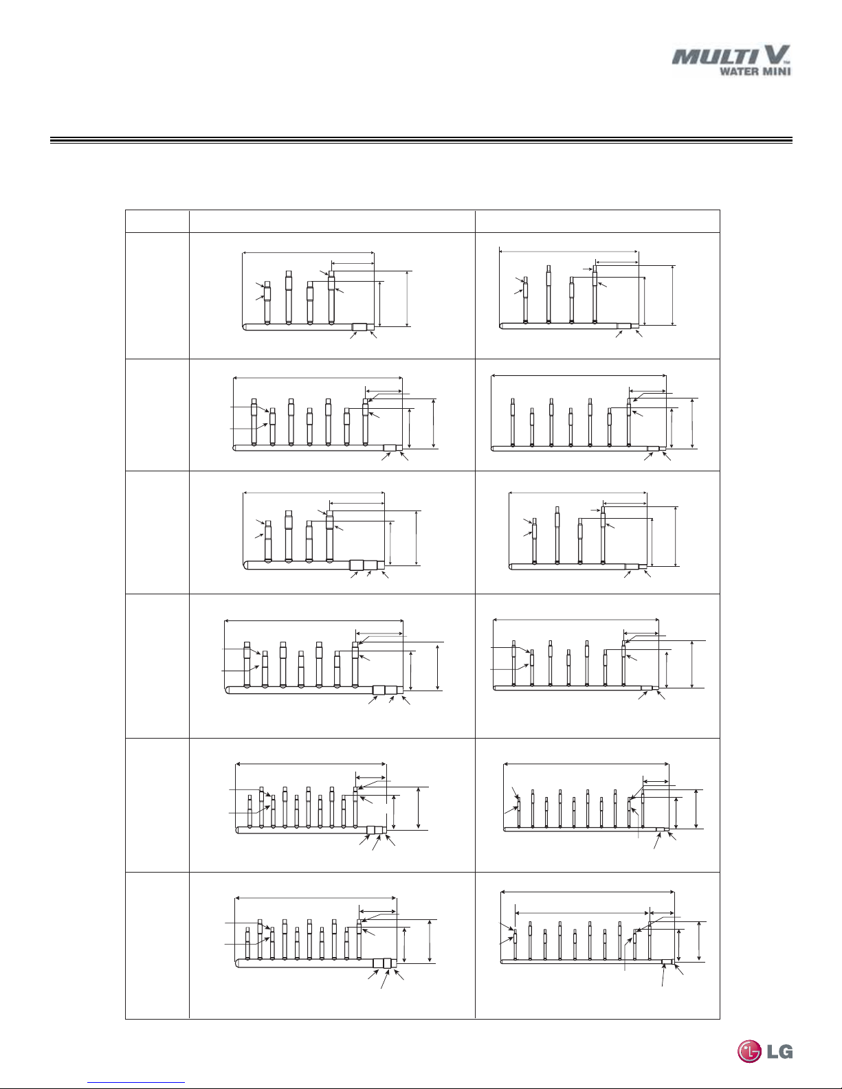
Table 12: Y-Branches and Headers.
Y-branches
4 branch 7 branch 10 branch
ARBLN01621 ARBL054 ARBL057 ARBL1010
ARBLN03321 ARBL104 ARBL107 ARBL2010
• If the diameter of the branch pipe segments differ from that of the designated refrigerant piping, trim the to the desired section using a pipe
cutter, and then use an adapter to connect.
• Always follow manufacturer’s guidelines on refrigerant piping restrictions such as maximum length, elevation difference, and diameters. Failure to do so can result in reduced heating / cooling performance or equipment malfunction.
Headers
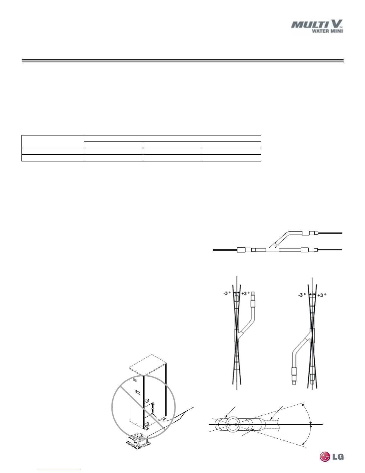
LG Y-branch kits consist of:
• Y-branches (liquid line, vapor lines).
• Reducer fittings as applicable.
• Molded clam-shell type insulation covers.
Y-Branch Kits
LG supplied Y-branches must be used at each transition. Field-supplied “T” fittings or “Y” branches are not acceptable. Each LG supplied Y-branch kit comes
with two (2) Y-branches for indoor units, step-down pipe reducers, and insulation
covers.
Y-branches may be installed in horizontal or vertical configurations. When installed vertically, position the Y-branch so the straight-through leg is ±3° of plumb.
When installed horizontally, position the Y-branch so the take-off leg is level and
shares the same horizontal plane as the straight-through leg ±5° rotation.
There is no limitation on the number of Y-branches that can be installed, but there
is a limitation on the number of indoor units connected to a single water source
unit.
Y-branches should always be installed with the single port facing the water-source
MULTI V Water Mini System Installation Manual
unit, the two-port end facing indoor units (Do not install Y-branches backwards as
shown in Figure 15.) Refrigerant flow cannot make U-turns through Y-branches.
The first Y-branch kit must be located at least three (3) feet from the water source
unit. Provide a minimum of 20
inches between a Y-branch and
any other fittings or indoor unit
piped in series. It is recommended that when a Y-branch is
located in a pipe chase or other
concealed space, access doors
should be provided for inspection access. The equivalent pipe
length of each Y-branch (1.6′)
must be added to each pipe
segment entered into LATS piping design software.
24
Figure 15: Diagram of an Incorrect Y-branch
Installation.
Due to our policy of continuous product innovation, some specifications may change without notification.
©LG Electronics U.S.A., Inc., Englewood Cliffs, NJ. All rights reserved. “LG” is a registered trademark of LG Corp.
LG Header kits consist of:
• Two Headers (one liquid line, one vapor line).
• Reducer fittings as applicable.
• Molded clam-shell type insulation covers.
Figure 12: Y-branch Connections.
Figure 13: Y-branch Installation Alignment Specication.
Vertical up conguration.
Figure 14: Horizontal Conguration End View.
Straight-through Leg
To next branch
To indoor unit
Y-branch Inlet
Vertical down conguration.
Branch Leg
Horizontal Plane
±5°
Note:
Smaller IDUs
Connect IDUs
Largest IDU
Header Inlet
Header End View
+0.0
-0.0
REFRIGERANT PIPING DESIGN
System Engineering
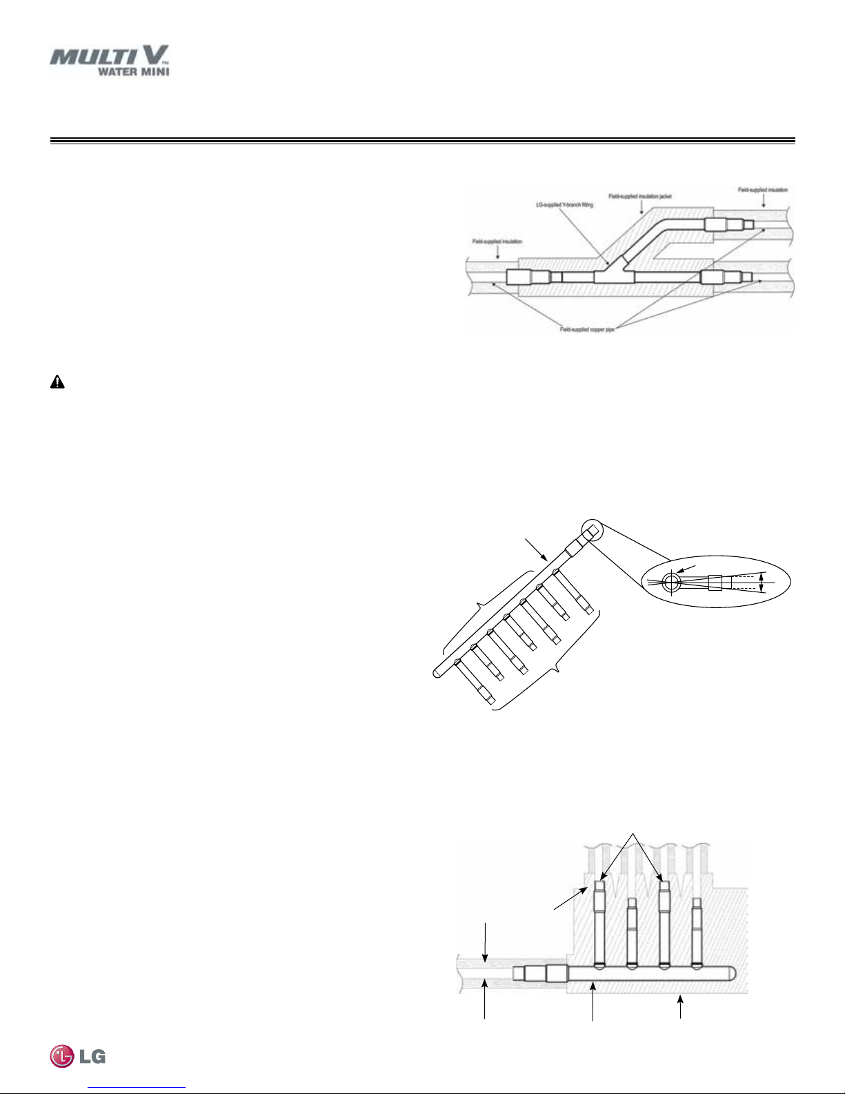
Y-branch Insulation
Figure 16: Y-branch Insulation and Pipe Detail.
Each Y-branch kit comes with clam-shell type peel-and-stick insulation jackets
molded to t the Y-branch ttings—one for the liquid line, one for the vapor line.
• Check the t of the Y-branch clam-shell insulation jacket after the Y-branch is
installed.
• Mark the pipe where the insulation jacket ends.
• Remove the jacket.
• Install eld-provided insulation on the three (3) pipes rst.
• Peel the adhesive glue protector slip and install the clam-shell jacket over the
tting.
Header Kits
Install Correctly
• Y-branches can be installed upstream between the Header and the water-source unit, but a Y-branch cannot be installed between a
header and an indoor unit.
• To avoid the potential of uneven refrigerant distribution through a header fitting, minimize the difference in equivalent pipe length
between the header fitting and each connected indoor unit.
Header kits are intended for use where multiple indoor units are in
the same vicinity and it would be better to “home-run” the run-out
pipes back to a centralized location. If connecting multiple indoor
units that are far apart, Y-branches may be more economical. See
page 16 for Header kit specifications and capacities.
Y-branches can be installed between the Header and the water
source unit, but a Y-branch cannot be installed between a Header
and an indoor unit. Headers must be installed in a horizontal and
level position with the distribution ports of the fitting in the same
horizontal plane as the straight-through branch.
When connecting indoor units to a Header, always connect the unit
with the largest nominal capacity to the port closest to the water
source unit. Then install the next largest indoor unit to the next port,
working down to the smallest indoor unit. Do not skip ports.
All indoor units must be mounted at an elevation below the Header fitting. All indoor units connected to a single Header fitting should be
located with an elevation difference between indoor units that does not exceed 49 feet. If indoor units are located at an elevation the same
as or above the Header fitting, do not use a Header. Instead, install a Y-branch fitting between the water source unit and the Header fitting,
and connect the elevated indoor unit to the Y-branch.
Figure 18: Header Kit—Horizontal Rotation Limit (Must be Installed
Level with No Rotation).
Refrigerant Piping
Header Insulation
Each Header kit comes with clam-shell type peel and stick insulation
jackets molded to fit the Header fittings—one for the liquid line and
one for the vapor line.
Due to our policy of continuous product innovation, some specifications may change without notification.
©LG Electronics U.S.A., Inc., Englewood Cliffs, NJ. All rights reserved. “LG” is a registered trademark of LG Corp.
Figure 17: Header Insulation and Pipe Detail.
Field supplied copper pipe
Field supplied insulation
Field supplied copper pipe
LG supplied insulation jacketLG supplied header
25
3X
REFRIGERANT PIPING DESIGN
System Engineering
No Pipe Size Substitutions
Use only the pipe size selected by the LATS Multi V pipe system design software. Using a different size is prohibited and may result in a
system malfunction or failure to work at all.
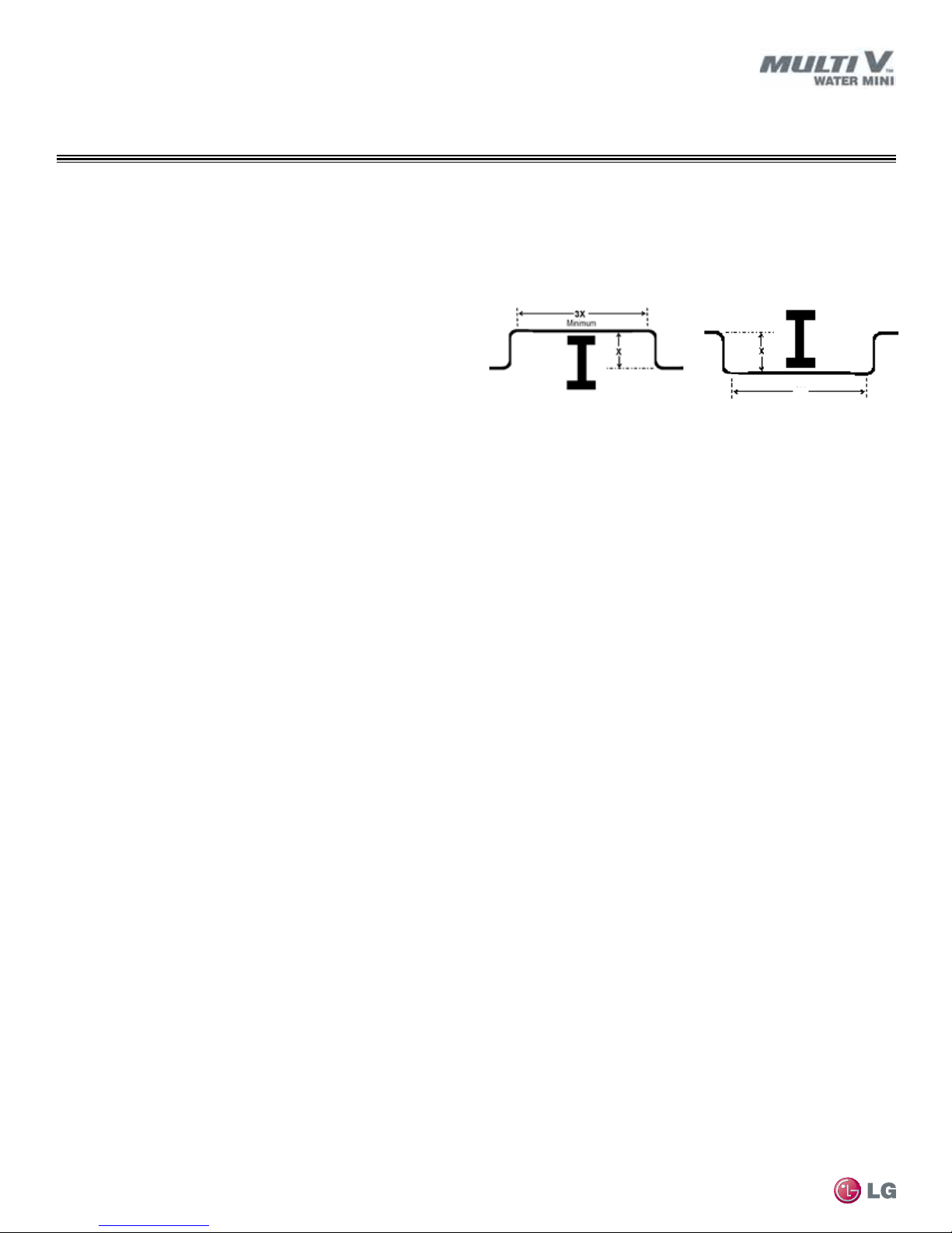
Obstacles
When an obstacle, such as an I-beam or concrete T, is in the path
of the planned refrigerant pipe run, it is best practice to route the
pipe over the obstacle. If adequate space is not available to route
the insulated pipe over the obstacle, then route the pipe under the
obstacle. In either case, it is imperative the length of the horizontal
section of pipe above or below the obstacle be a minimum of three
(3) times the longest vertical rise (or fall) at either end of the
segment.
Copper Expansion and Contraction
Under normal operating conditions, the vapor pipe temperature of a
Multi IV system can vary as much as 280°F. With this large variance
in pipe temperature, the designer must consider pipe
expansion and contraction to avoid pipe and fitting fatigue failures.
Refrigerant pipe along with the insulation jacket form a cohesive
unit that expands and contracts together. During system operation,
thermal heat transfer occurs between the pipe and the surrounding
insulation.
If the pipe is mounted in free air space, no natural restriction to
movement is present if mounting clamps are properly spaced and
installed. When the refrigerant pipe is mounted underground in a
utility duct stacked among other pipes, natural restriction to linear
movement is present. In extreme cases, the restrictive force of
surface friction between insulating jackets could become so great
that natural expansion ceases and the pipe is “fixed” in place. In this
situation, opposing force caused by change in refrigerant fluid/vapor
temperature can lead to pipe/fitting stress failure.
The refrigerant pipe support system must be engineered to allow
free expansion to occur. When a segment of pipe is mounted
MULTI V Water Mini System Installation Manual
between two fixed points, provisions must be provided to allow pipe
expansion to naturally occur. The most common method is the
inclusion of expansion Loop or U-bends. See Figure 20 on page 28.
Each segment of pipe has a natural fixed point where no
movement occurs. This fixed point is located at the center point
of the segment assuming the entire pipe is insulated in a similar
fashion. The natural fixed point of the pipe segment is typically
where the expansion Loop or U-bend should be. Linear pipe
expansion can be calculated using the following formula:
LE = C x L x (Tr – Ta) x 12
LE = Anticipated linear tubing expansion (in.)
C = Constant (For copper = 9.2 x 10⁻⁶ in./in.°F)
L = Length of pipe (ft.)
T
= Refrigerant pipe temperature (°F)
R
T
= Ambient air temperature (°F)
a
12 = Inches to feet conversion (12 in./ft.)
Figure 19: Installing Piping Above and Below an Obstacle.
Above an obstacle.
1. From Table 13, find the row corresponding with the actual length
of the straight pipe segment.
2. Estimate the minimum and maximum temperature of the pipe.
In the column showing the minimum pipe temperature, look up the
anticipated expansion distance. Do the same for the maximum
pipe temperature.
3. Calculate the difference in the two expansion distance values.
The result will be the anticipated change in pipe length.
Below an obstacle.
General Example:
A Multi V system is installed and the design shows that there is a
130 feet straight segment of tubing between a Y-branch and an
indoor unit. In heating, this pipe transports hot gas vapor to the
indoor units at 120°F. In cooling, the same tube is a suction line
returning refrigerant vapor to the water source unit at 40°F. Look up
the copper tubing expansion at each temperature and calculate the
difference.
Vapor Line
Transporting Hot Vapor: 130 ft. pipe at 120°F = 1.54 in.
Transporting Suction Vapor: 130 ft. pipe at 40°F = 0.52 in.
Anticipated Change in Length: 1.54 in. – 0.52 in. = 1.02 in.
Liquid Line
The liquid temperature remains relatively the same temperature; only
the direction of flow will reverse. Therefore, no significant change in
length of the liquid line is anticipated.
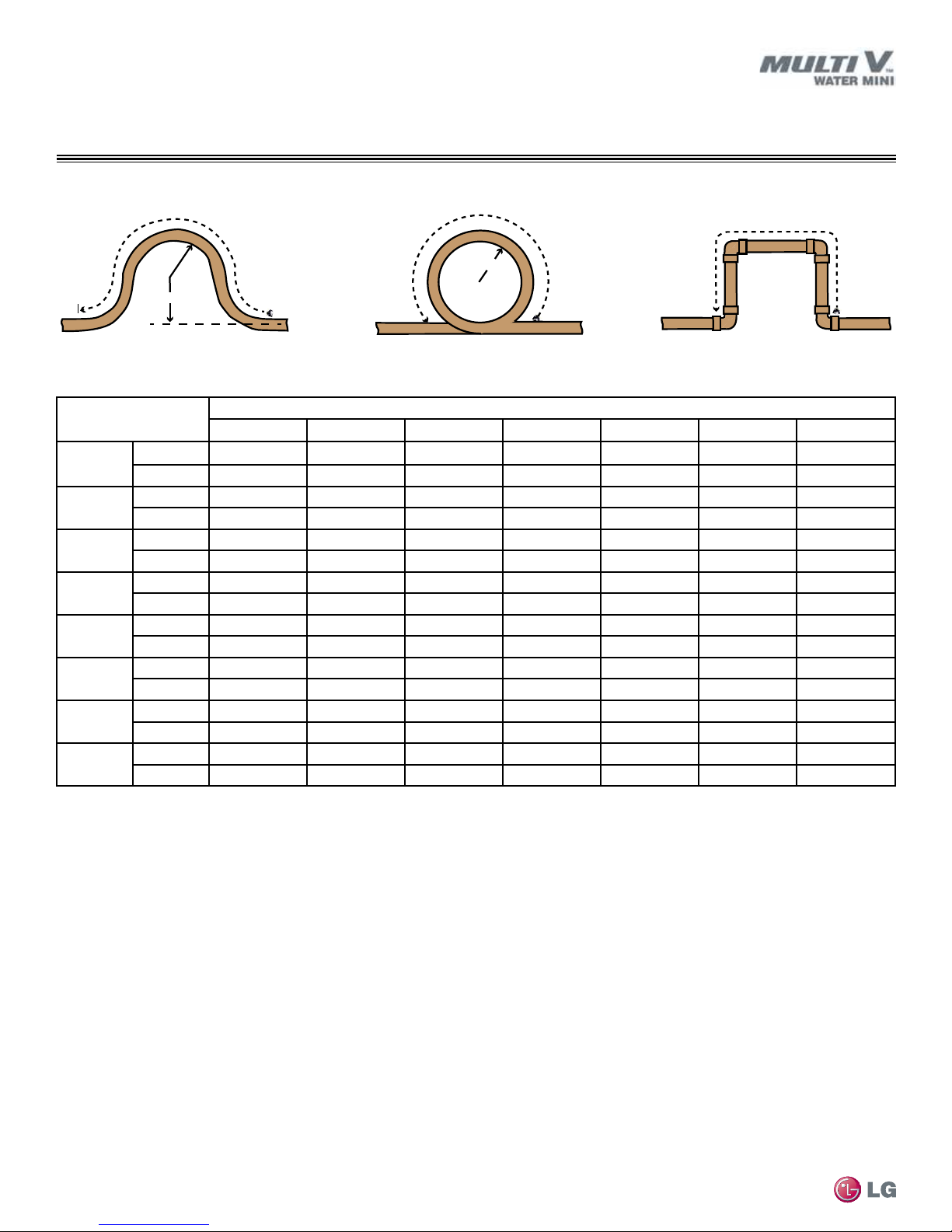
When creating an expansion joint, the joint height should be a
minimum of two times the joint width. Although different types of
expansion arrangements are available, the data for correctly sizing
an Expansion Loop is provided in Table 14. Use soft copper with
long radius bends on longer runs or long radius elbows for shorter
pipe segments. Using the anticipated linear expansion (LE) distance
calculated, look up the Expansion Loop or U-bend minimum design
dimensions. If other types of expansion joints are chosen, design
per ASTM B-88 Standards.
26
Due to our policy of continuous product innovation, some specifications may change without notification.
©LG Electronics U.S.A., Inc., Englewood Cliffs, NJ. All rights reserved. “LG” is a registered trademark of LG Corp.
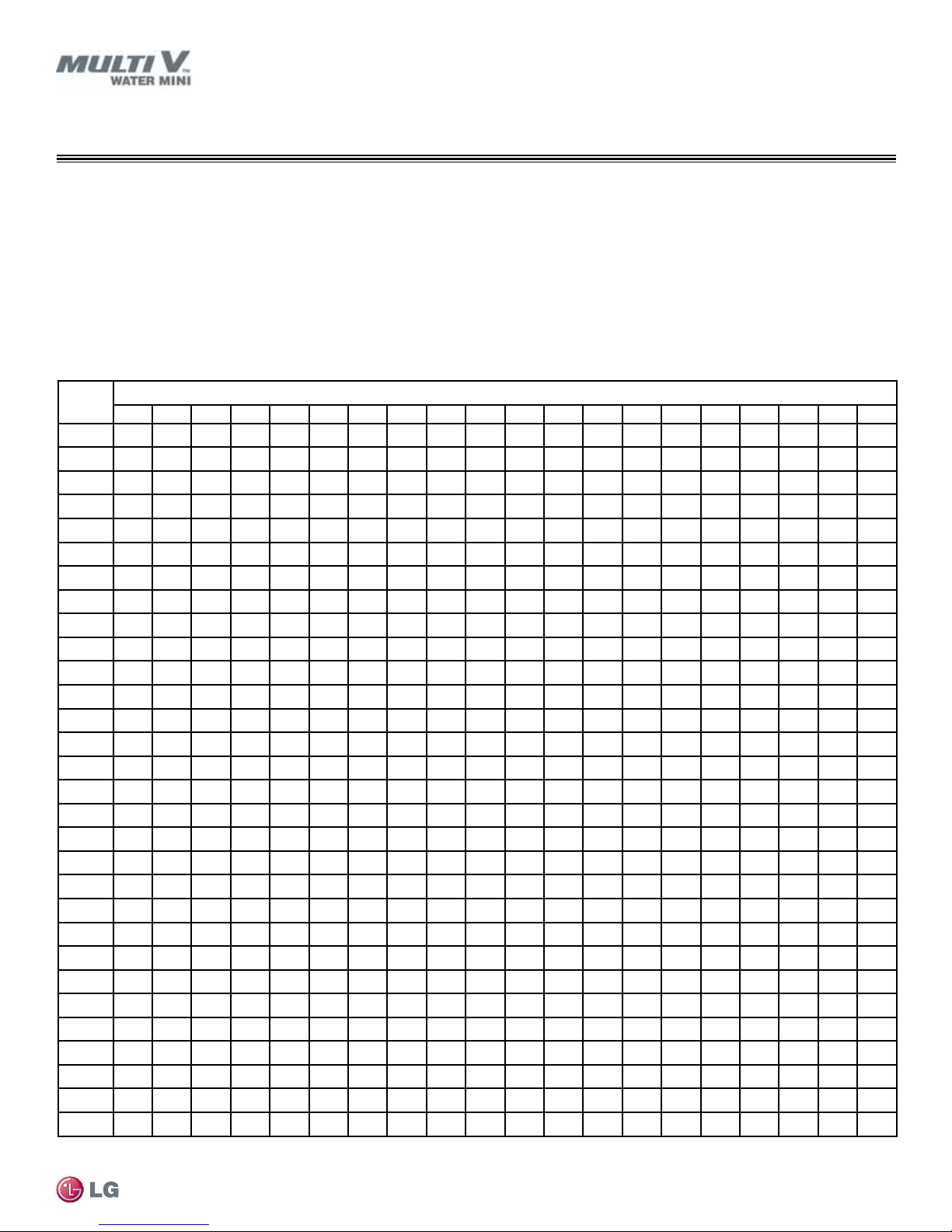
See table below for precalculated anticipated expansion for various pipe sizes and lengths of refrigerant tubing.
To find the anticipated expansion value:
1. From the table below, find the row corresponding with the actual feet of the straight pipe segment.
2. Estimate the minimum and maximum temperature of the pipe.
3. In the column showing the minimum pipe temperature, look up the anticipated expansion distance corresponding to the segment length.
Do the same for the maximum pipe temperature.
4. Calculate the difference in the two expansion distance values. The result will be the change in pipe length.
Table 13: Linear Thermal Expansion of Copper Tubing in Inches.
Pipe
1
Length
100 0.40 0.40 0.50 0.60 0.65 0.70 0.75 0.80 0.85 0.90 0.95 1.00 1.05 1.10 1.08 1.15 1.30 1.40 1.45 1.50
120 0.48 0.48 0.60 0.72 0.78 0.84 0.90 0.96 1.02 1.08 1.14 1.20 1.26 1.32 1.30 1.38 1.56 1.68 1.74 1.80
140 0.56 0.56 0.70 0.84 0.91 0.98 1.05 1.12 1.19 1.26 1.33 1.40 1.47 1.54 1.51 1.61 1.82 1.96 2.03 2.10
160 0.64 0.64 0.80 0.96 1.04 1.12 1.20 1.28 1.36 1.44 1.52 1.60 1.68 1.76 1.73 1.84 2.08 2.24 2.32 2.40
180 0.72 0.72 0.90 1.08 1.17 1.26 1.35 1.44 1.53 1.62 1.71 1.80 1.89 1.98 1.94 2.07 2.34 2.52 2.61 2.70
200 0.80 0.80 1.00 1.20 1.30 1.40 1.50 1.60 1.70 1.80 1.90 2.00 2.10 2.20 2.16 2.30 2.60 2.80 2.90 3.00
220 0.88 0.88 1.10 1.32 1.43 1.54 1.65 1.76 1.87 1.98 2.09 2.20 2.31 2.42 2.38 2.53 2.86 3.08 3.19 3.30
240 0.96 0.96 1.20 1.44 1.56 1.68 1.80 1.92 2.04 2.16 2.28 2.40 2.52 2.64 2.59 2.76 3.12 3.36 3.48 3.60
260 1.04 1.04 1.30 1.56 1.69 1.82 1.95 2.08 2.21 2.34 2.47 2.60 2.73 2.86 2.81 2.99 3.38 3.64
280 1.12 1.12 1.40 1.68 1.82 1.96 2.10 2.24 2.38 2.52 2.66 2.80 2.94 3.08 3.02 3.22 3.64 3.92 4.06 4.20
300 1.20 1.20 1.50 1.80 1.95 2.10 2.25 2.40 2.55 2.70 2.85 3.00 3.15 3.30 3.24 3.45 3.90 4.20 4.35 4.50
320 1.28 1.28 1.60 1.92 2.08 2.24 2.40 2.56 2.72 2.88 3.04 3.20 3.36 3.52 3.46 3.68 4.16 4.48 4.64 4.80
340 1.36 1.36 1.70 2.04 2.21 2.38 2.55 2.72 2.89 3.06 3.23 3.40 3.57 3.74 3.67 3.91 4.42 4.76 4.93 5.10
360 1.44 1.44 1.80 2.16 2.34 2.52 2.70 2.88 3.06 3.24 3.42 3.60 3.78 3.96 3.89 4.14 4.68 5.04 5.22 5.40
380 1.52 1.52 1.90 2.28 2.47 2.66 2.85 3.04 3.23 3.42 3.61 3.80 3.99 4.18 4.10 4.37 4.94 5.32 5.51 5.70
400 1.60 1.60 2.00 2.40 2.60 2.80 3.00 3.20 3.40 3.60 3.80 4.00 4.20 4.40 4.32 4.60 5.20 5.60 5.80 6.00
420 1.68 1.68 2.10 2.52 2.73 2.94 3.15 3.36 3.57 3.78 3.99 4.20 4.41 4.62 4.54 4.83 5.46 5.88 6.09 6.30
440 1.76 1.76 2.20 2.64 2.86 3.08 3.30 3.52 3.74 3.96 4.18 4.40 4.62 4.84 4.75 5.06 5.72 6.16 6.38 6.60
460 1.84 1.84 2.30 2.76 2.99 3.22 3.45 3.68 3.91 4.14 4.37 4.60 4.83 5.06 4.97 5.29 5.98 6.44 6.67 6.90
480 1.92 1.92 2.40 2.88 3.12 3.36 3.60 3.84 4.08 4.32 4.56 4.80 5.04 5.28 5.18 5.52 6.24 6.72 6.96 7.20
500 2.00 2.00 2.50 3.00 3.25 3.50 3.75 4.00 4.25 4.50 4.75 5.00 5.25 5.50 5.40 5.75 6.50 7.00 7.25 7.50
1
Pipe length baseline temperature = 0°F. "Expansion of Carbon, Copper and Stainless Steel Pipe," The Engineers' Toolbox, www.engineeringtoolbox.
com.
35° 40° 45° 50° 55° 60° 65° 70° 75° 80° 85° 90° 95° 100° 105° 110° 115° 120° 125° 130°
10 0.04 0.04 0.05 0.06 0.06 0.07 0.08 0.08 0.09 0.09 0.10 0.10 0.11 0.11 0.11 0.12 0.13 0.14 0.15 0.15
20 0.08 0.08 0.10 0.12 0.13 0.14 0.15 0.16 0.17 0.18 0.19 0.20 0.21 0.22 0.22 0.23 0.26 0.28 0.29 0.30
30 0.12 0.12 0.15 0.18 0.20 0.21 0.23 0.24 0.26 0.27 0.29 0.30 0.32 0.33 0.32 0.35 0.39 0.42 0.44 0.45
40 0.16 0.16 0.20 0.24 0.26 0.28 0.30 0.32 0.34 0.36 0.38 0.40 0.42 0.44 0.43 0.46 0.52 0.56 0.58 0.60
50 0.20 0.20 0.25 0.30 0.33 0.35 0.38 0.40 0.43 0.45 0.48 0.50 0.53 0.55 0.54 0.58 0.65 0.70 0.73 0.75
60 0.24 0.24 0.30 0.36 0.39 0.42 0.45 0.48 0.51 0.54 0.57 0.60 0.63 0.66 0.65 0.69 0.78 0.84 0.87 0.90
70 0.28 0.28 0.35 0.42 0.46 0.49 0.53 0.56 0.60 0.63 0.67 0.70 0.74 0.77 0.76 0.81 0.91 0.98 1.02 1.05
80 0.32 0.32 0.40 0.48 0.52 0.56 0.60 0.64 0.68 0.72 0.76 0.80 0.84 0.88 0.86 0.92 1.04 1.12 1.16 1.20
90 0.36 0.36 0.45 0.54 0.59 0.63 0.68 0.72 0.77 0.81 0.86 0.90 0.95 0.99 0.97 1.04 1.17 1.26 1.31 1.35
Due to our policy of continuous product innovation, some specifications may change without notification.
©LG Electronics U.S.A., Inc., Englewood Cliffs, NJ. All rights reserved. “LG” is a registered trademark of LG Corp.
REFRIGERANT PIPING DESIGN
System Engineering
Fluid Temperature °F
Refrigerant Piping
3.77 3.90
27
R
L
L
R
L
L
R
L
L
REFRIGERANT PIPING DESIGN
System Engineering
Figure 20: Coiled Expansion Loops and Offsets.
Large Tubing U-bend (>3/4 in.) Loop Small Tubing U-bend (<3/4 in.)
Table 14: Radii of Coiled Expansion Loops and Developed Lengths of Expansion Offsets.
Anticipated Linear
Expansion (LE) (in)
1
1/2
1
1-1/2
2
2-1/2
3
3-1/2
4
1
R = Centerline Length of Pipe.
2
L = Centerline Minimum Radius (inches).
R
2
L
1
R
2
L
1
R
2
L
1
R
2
L
1
R
2
L
1
R
2
L
1
R
2
L
1
R
2
L
1/4 3/8 1/2 3/4 1 1-1/4 1-1/2
6 7 8 9 11 12 13
38 44 50 59 67 74 80
9 10 11 13 15 17 18
54 63 70 83 94 104 113
11 12 14 16 18 20 22
66 77 86 101 115 127 138
12 14 16 19 21 23 25
77 89 99 117 133 147 160
14 16 18 21 24 26 29
86 99 111 131 149 165 179
15 17 19 23 26 29 31
94 109 122 143 163 180 196
16 19 21 25 28 31 34
102 117 131 155 176 195 212
17 20 22 26 30 33 36
109 126 140 166 188 208 226
Nominal Tube Size (OD) inches
MULTI V Water Mini System Installation Manual
28
Due to our policy of continuous product innovation, some specifications may change without notification.
©LG Electronics U.S.A., Inc., Englewood Cliffs, NJ. All rights reserved. “LG” is a registered trademark of LG Corp.
 Loading...