

LG MultiSITE CRC1 Series, MultiSITE CRC1+ Installation Manual
MultiSITE CRC1 Series Controllers
INSTALLATION MANUAL
PREMTBVC0 – MultiSITE CRC1
PREMTBVC1 – MultiSITE CRC1+
09-26-2017
2:43 PM
Occ Auto Heat
74°
78
Indoor °F
Humidity
66 %
68
Auto

The instructions included in this manual must be followed to prevent
product malfunction, property damage, injury, or death to the user
or other people. Incorrect operation due to ignoring any instructions
will cause harm or damage. A summary of safety precautions begins
on page 4.
Do not throw away, destroy, or lose this manual.
Please read carefully and store in a safe place for future reference.
Content familiarity required for proper installation and operation.
For more technical materials such as submittals, engineering
databooks, and catalogs, visit www.lghvac.com.
For continual product development, LG Electronics U.S.A., Inc., reserves the right to
change specifications without notice.
©LG Electronics U.S.A., Inc.
This document, as well as all reports, illustrations, data, information, and other materials
are the property of LG Electronics U.S.A., Inc.
PROPRIETARY DATA NOTICE
This document, as well as all reports, illustrations, data, information, and other
materials are the property of LG Electronics U.S.A., Inc., and are
disclosed by LG Electronics U.S.A., Inc., only in confidence.
IM_CRC1_Series_Controllers_10_16

TABLE OF CONTENTS
Safety Instructions ...............................................................................................4
Introduction ..........................................................................................................7
MultiSITE CRC1 Series Controllers ..............................................................................7
Compatible Equipment .................................................................................................7
Accessories ..................................................................................................................7
Safety ...........................................................................................................................7
Controller Overview .............................................................................................8
Home Screen ................................................................................................................8
Selecting Installation Location ......................................................................................9
Controller Installation ...........................................................................................9
Installing the Controller ...............................................................................................10
Controller Setup .................................................................................................13
Controller Setup ..........................................................................................................13
Setpoint Adjustment ....................................................................................................14
Accessories Installation .....................................................................................16
ZigBee Pro Wireless Module ......................................................................................16
Ceiling Motion Sensor ................................................................................................18
Wall Mounted Motion Sensor ......................................................................................21
Door/Window Sensor ..................................................................................................24
ZigBee Setup .....................................................................................................28
ZigBee Pro Quick Setup .............................................................................................28
BACnet MS/TP Setup ........................................................................................30
4
MultiSITE CRC 1 Controller
Due to our policy of continuous product innovation, some specifications may change without notification.
©LG Electronics U.S.A., Inc., Englewood Cliffs, NJ. All rights reserved. “LG” is a registered trademark of LG Corp.
The instructions below must be followed to prevent product malfunction, property
damage, injury or death to the user or other people. Incorrect operation due to ignoring any instructions will cause harm or damage. The level of seriousness is classified by the symbols below.
SAFETY INSTRUCTIONS
WARNING
The information in this manual is intended for use by a trained technician
familiar with the U.S. National Electric Code (NEC) who is equipped with the
proper tools and test instruments.
Failure to carefully read and follow all instructions in this manual may result in equipment
malfunction, property damage, personal injury and/or death.
DANGER
This symbol indicates an imminently hazardous situation
which, if not avoided, will result in death or serious injury.
WARNING
This symbol indicates a potentially hazardous situation
which, if not avoided, could result in death or serious injury.
CAUTION
This symbol indicates a potentially hazardous situation
which, if not avoided, may result in minor or moderate
injury.
Note:
This symbol indicates situations that may result in equipment or property damage accidents only.
This symbol indicates an action that should not be
performed.
TABLE OF SYMBOLS
DANGER
Do not touch any exposed outdoor unit wiring, terminals, or other elec-
trical components with tools or exposed skin. Only qualied technicians
should install, use or remove this unit.
Improper installation or use may result in re, explosion, electric shock, physical injury
and/or death.
Don’t use or store ammable gas or combustibles near an outdoor or
indoor unit.
There is risk of re, explosion, and physical injury or death.

5
Installation Manual
Due to our policy of continuous product innovation, some specifications may change without notification.
©LG Electronics U.S.A., Inc., Englewood Cliffs, NJ. All rights reserved. “LG” is a registered trademark of LG Corp.
SAFETY INSTRUCTIONS
Do not install the MultiSITE Controller unit if it will be exposed to rain or
other precipitation.
Do not install the unit in a location exposed to open
ame or extreme heat.
Do not touch the unit with wet hands.
There is risk of re, electric shock, physical injury and/or death.
Replace all control box and panel covers.
If cover panels are not installed securely, dust, water and animals may enter the unit,
causing re, electric shock, and physical injury or death.
Wear protective gloves when handling equipment.
Sharp edges may cause personal injury.
Dispose of any packing materials safely.
• Packing materials, such as nails and other metal or wooden parts may cause puncture wounds or other injuries.
• Tear apart and throw away plastic packaging bags so that children may not play
with them and risk suffocation and death.
Do not change the settings of the protection devices.
If the pressure switch, thermal switch, or other protection device is shorted and forced
to operate improperly, or parts other than those specied by LG are used, there is risk of
re, electric shock, explosion, and physical injury or death.
If the air conditioner is installed in a small space, take measures to prevent
the refrigerant concentration from exceeding safety limits in the event of a
refrigerant leak.
Consult the latest edition of ASHRAE (American Society of Heating, Refrigerating, and
Air Conditioning Engineers) Standard 15. If the refrigerant leaks and safety limits are
exceeded, it could result in personal injuries or death from oxygen depletion.
Note:
MultiSITE Controller is for use with select LG commercial air conditioning
systems only.
Do not attempt to use MultiSITE Controller with any other
type of system. Refer to the compatible equipment list in this manual.
There is risk of equipment damage or degraded performance
Do not cut, lengthen or shorten the cable between the MultiSITE Control-
ler unit and the indoor unit.
Do not install the MultiSITE Controller unit in
a location where the cable cannot be safely and easily connected between
the two units.
Do not allow strain on this cable.
There is risk of equipment damage.
6
MultiSITE CRC 1 Controller
Due to our policy of continuous product innovation, some specifications may change without notification.
©LG Electronics U.S.A., Inc., Englewood Cliffs, NJ. All rights reserved. “LG” is a registered trademark of LG Corp.
Note:
Clean up the site after all procedures are nished, and check that no metal
scraps, screws, or bits of wiring have been left inside or surrounding the
controller or indoor units.
Provide power to the outdoor unit compressor crankcase heaters at least
six (6) hours before operation begins.
Starting operation with a cold compressor sump(s) may result in severe bearing damage
to the compressor(s). Keep the power switch on during the operational season.
Do not block the indoor unit inlet or outlet.
Unit may malfunction.
Securely attach the electrical cover to the indoor unit. Non-secured covers
can result in re due to dust or water in the service panel.
Do not allow water, dirt, or animals to enter the unit.
There is risk of unit failure or degraded performance.
Do not spill water or other liquid on the inside of the indoor unit, espe-
cially on electrical components.
Do not drop the MultiSITE Controller
unit into water. If the unit is immersed in water or other liquid, contact your
local authorized LG distributor for support.
There is risk of unit failure or degraded performance.
Electronic controls are static sensitive devices.
Discharge yourself correctly before manipulating and installing the MultiSITE Controller.
This device must be installed to provide a separation distance of at least
8 inches from all persons and must not be located or operating in conjunction with any other antenna or transmitter.
Operation is subject to the following two conditions: (1) this device may
not cause interference, and (2) this device must accept any interference,
including interference that may cause undesired operation of the device.
A short circuit or wrong wiring may permanently damage Remote Controller or equipment.
SAFETY INSTRUCTIONS
7
Installation Manual
Due to our policy of continuous product innovation, some specifications may change without notification.
©LG Electronics U.S.A., Inc., Englewood Cliffs, NJ. All rights reserved. “LG” is a registered trademark of LG Corp.
INTRODUCTION
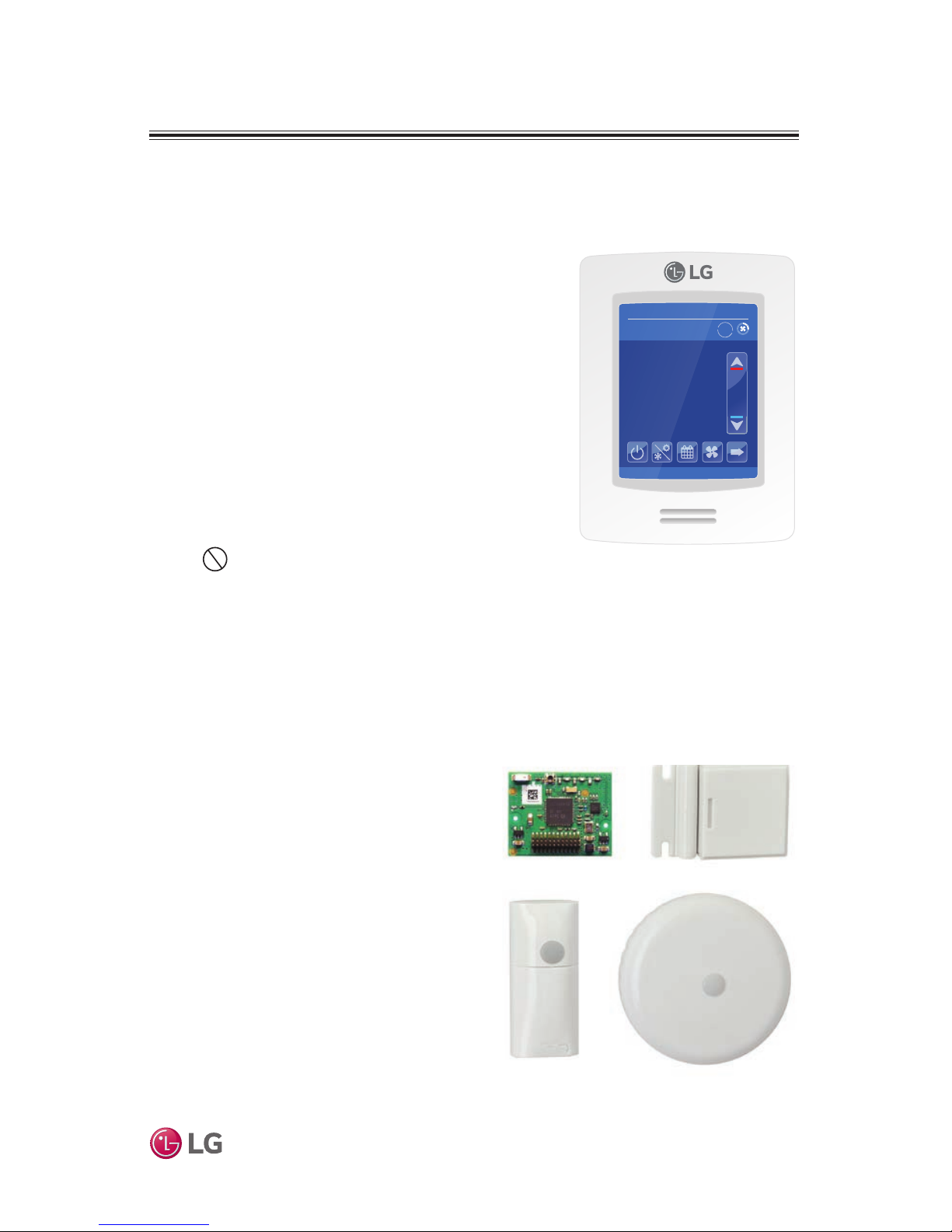
MultiSITE CRC1 Series Controllers
This manual describes how to install the LG MultiSITE Commercial Remote Controllers (CRC) 1 and the accessories
described below. There are two controller models:
• MultiSITE CRC1 (Model PREMTBVC0)
• MultiSITE CRC1+ (Model PREMTBVC1)
The two models are identical with the exception of two
functions included in the MultiSITE CRC1+ only:
• Motion sensor
• Humidity sensor
Compatible Equipment
MultiSITE CRC1 Controllers are compatible with LG
Commercial Air Conditioning indoor units (except PTAC
units). Do not attempt to use a MultiSITE CRC1
controller with any other equipment.
Accessories
These accessories are available for MultiSITE CRC1 controllers:
• ZigBee® Pro wireless card
Model ZVRCZPWC1
• Door and window switch
Model ZVRCZDWS1
• Wall mounted occupancy sensor
Model ZVRCZWOC1
• Ceiling mounted occupancy sensor
Model ZVRCZCOC1
The ZigBee® Pro wireless card is
required for communication between the
controller and the other accessories.
Safety
Safety of personnel is the primary
concern during all procedures. Read and
understand the safety summary at the
front of this manual.
Typical MultiSITE
CRC1 Controller
MultiSITE CRC1 Controller
Optional Accessories
09-26-2017
2:43 PM
Occ Auto Heat
74°
78
Indoor °F
Humidity
66 %
68
Auto
*ZigBee is a registered trademark of the ZigBee Alliance.
ZigBee® Pro Wireless Card Door/Window Switch
Wall Mounted
Occupancy Sensor
Ceiling Mounted
Occupancy Sensor
8
MultiSITE CRC 1 Controller
Due to our policy of continuous product innovation, some specifications may change without notification.
©LG Electronics U.S.A., Inc., Englewood Cliffs, NJ. All rights reserved. “LG” is a registered trademark of LG Corp.
CONTROLLER OVERVIEW
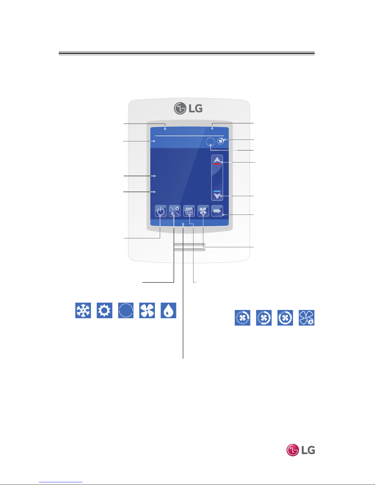
Home Screen
Note:
Available functions/features may differ based on the connected system.
When any change is made to a parameter, the value is automatically
saved in memory when the next parameter is selected or another page
is opened.
Arrows auto-increment/decrement at higher speed when holding button
for more than 2.5 seconds.
09-26-2017
2:43 PM
Occ Auto Heat
74°
78
Indoor °F
Humidity
66 %
68
Auto
Locked by central controller
Occupancy Status
Occupied (Occ) or
Unoccupied (Unocc)
Operation Mode
Status
Current Fan
Speed Setting
Up Arrow
Raise Temperature
Setpoint
Room Indoor
Temperature
Down Arrow
Lower Temperature Setpoint
On/Off
Turn the display
on or off
Schedule
Set weekly
schedule
More
Provides user with
access to less often
used functions.
Fan Speed
Set fan to Slow,
Low, Low-Med,
Medium, Med-High,
High, Power, Auto.
(Available options
depend on IDU
model.)
Operation Mode
Set Cool, Heat, Auto
Cool, Auto Heat, Fan,
Dry modes
Note: Pressing and holding
the Operation Mode icon
takes the user to the
Operation Mode page.
Short Network
Message
Note: Long-press of the
Fan Speed button when in
cooling mode triggers Power
Cooling mode. If in Power
Cooling mode, last airow
segment on top is lit in purple
and the text changes from
“Fan” to “Power Cool”. This
mode lasts for 30 minutes
and then reverts back to the
previous fan speed.
Auto
The controller home screen is shown and described below.
Current TimeCurrent Date
Room Indoor
Humidity
9
Installation Manual
Due to our policy of continuous product innovation, some specifications may change without notification.
©LG Electronics U.S.A., Inc., Englewood Cliffs, NJ. All rights reserved. “LG” is a registered trademark of LG Corp.
CONTROLLER INSTALLATION
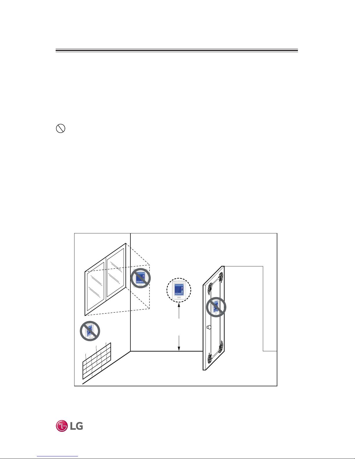
Selecting Installation Location
The room temperature sensor is inside the controller, so the installation
location is critical to proper system operation. Install the controller in a
location away from direct sunlight, high humidity, and direct flow of hot or
cold air. Install the controller on a flat, clean wall surface approximately 5 ft
above the floor in an area with good circulation and average temperature.
Do not install the controller where it is exposed to:
• Drafts or dead spots behind doors and in corners
• Hot or cold air from ducts
• Radiant heat from sun or appliances
• Concealed pipes or chimneys
• Uncontrolled areas such as on an outside wall
Refer to Figure 1 for a typical installation location.
Figure 1: Typical Controller Location
5ft
no
no
yes
09-26-2017
2:43 PM
Occ Auto Heat
74°
78
Indoor °F
Humidity
66 %
68
Auto
Locked by central controller
09-26-2017
2:43 PM
Occ Auto Heat
74°
78
Indoor °F
Humidity
66 %
68
Auto
Locked by central controller
no
10
MultiSITE CRC 1 Controller
Due to our policy of continuous product innovation, some specifications may change without notification.
©LG Electronics U.S.A., Inc., Englewood Cliffs, NJ. All rights reserved. “LG” is a registered trademark of LG Corp.
CONTROLLER INSTALLATION
Installing the Controller
Follow this procedure to install the controller.
Note:
• If replacing an existing MultiSITE CRC1 Series Remote Controller, label the wires
before removal.
• Electronic controls are static sensitive devices. Discharge yourself properly before
manipulating and installing the Remote Controller.
• A short circuit or wrong wiring may permanently damage the Remote Controller or
the equipment.
• This Remote Controller must be installed to provide a separation distance of at
least 8 inches from all persons and must not be collocated or operating in conjunction with any other antenna or transmitter.
• If your installation includes wireless accessories, you can install the optional
ZigBee Pro wireless module when the controller case is open. Refer to page 16
for Zigbee Pro wireless module installation instructions.
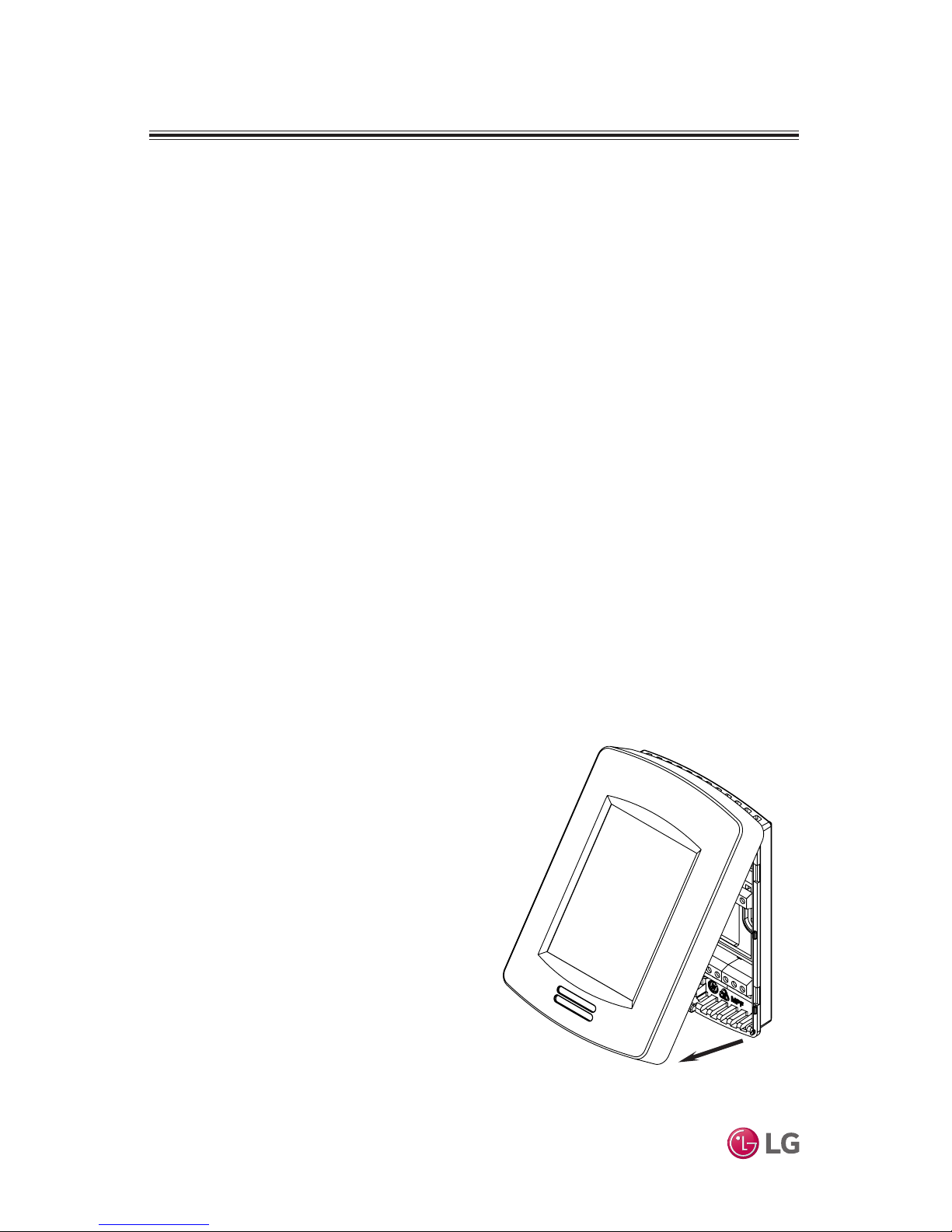
Figure 2: Open Cover
1. Remove security screw (if any) on
bottom of Remote Controller cover
(Figure 2).
2. Read FCC ID and IC label installed
in cover before installing any wireless product.
3. Ensure correct side of base faces
up.
4. Pull cables 6 inches out from wall.
5. Align base and mark location of two
mounting holes on wall
(Figure 3).
6. Install anchors in wall.
7. Insert wires through center opening
of base.
8. Insert screws in mounting holes on
each side of base.
9. Strip each wire 1/4 inch from end.
 Loading...