

LG MU-50PZ41A, MU-50PZ40, MU-50PZ41, MU-50PZ40A, MU-50PZ40B Owner's Manual
...
PLASMA MONITOR
OWNER'S MANUAL
MODEL : MU-50PZ40/41
MU-50PZ40A/41 A
MU-50PZ40B!41 B
....................... .......... a U-50PZ40 R/41R
...............;;;;; MU-S0PZ40S/41S
MU-50PZ40Ki41 K
I carefully before operating the
J require service,
luote
WARNING"
TO REDUCE THE R_SK OF ELECTRIC SHOCK DO NOT REMOVE COVER (OR BACK). NO
USER SERVICEABLE PARTS _NSIDE REFER TO QUALIFIED SERVICE PERSONNEL
WARNING
,_ The lightning f_ash with arrowhead symbol, wffhin an equilateral triangle, is intended to alert the
user to the presence of uninsu]ated "dangerous vo_age _'within the product's enclosure that may
be of sufficient magnitude to constff_e a risk of electric shock to persons.
The exclamation point within an equiiateral triangle is intended to aied the user to the presence
of important operating and maintenance (servicing) instructions in the literature accompanying
the appliance.
WARNING"
TO PREVENT FIRE OR SHOCK HAZARDS, DO NOT EXPOSE THIS PRODUCT TO RAEN OR MOiS-
TURE
FCC NOTICE
• MU-50PZ41/A/BIKIRIS : A Class A digital device
This eqaipmec:[ t_as been tested and found to comply with the limits for a Class A digital device, pursuant to
P_ 15 of the FCC Rules. These limits are designed _o provide reasonable protection against harmful inter-
ference when the equipment is operated in a _mmercia_ environment This _uipment generates, uses,
and can radiate radio frequency energy and, if not instated and used in accordance with the instruction man-
uaJ may cause harmful interference to radio communications. Operation of this equipment in a reside_ial
area is _ike_yto cause harmful interference in which case the user will be required to correct the interference
at his own expense.
o MU-5OPZ4OiA/B/K/RIS : A Class B digital device
This equipment has b_n tested and found to comply with the limits for a Ctass B digitaJ device, pursuant
to Part t5 of the FCC Rules. These limits are designed to provide reasonable protection against harmful
interference in a residential installation. This equipment generates, uses and can radiate radio frequency
energy and, if not installed and used in accordance with the instructions, may cause harmful interference to
radio communications. However, there is no guarantee that interference wilt not occur in a particular instal-
_ation. ff this equipment does cause harmful interference to radio or television reception which cen be deter-
mined by turning the equipment off and on, the user is encouraged to try to correct the interference by one
or more of the feJlowing measures:
° Reorient or relocate the receiving _tenna
- Increase the separation between the equipment and receiver.
° Connect the equipment into an outlet on a circuit different from that to which the receiver is connected.
Consult #_e deaJer or an experienced radio%V technician for he_p
• Any changes or modifications not expressly approved by the party responsible for
compliance could void the user's authority to operate the equipment.
WARNING
TO REDUCE THE RISK OF FIRE AND ELECTRIC SHOCK, DO NOT EXPOSE THIS PRODUCT TO
RAIN OR MOISTURE.

SAFETY INSTRUCTIONS
/i- Important safeguards for you and your new product
Your product has been manufactured and tested with your _fety in mind, However, improper use can result in potentiai electrical
sl_ock or fire hazards. To avoid _feating the safeguards that have been built ir_o your new product, ptease read and obser,/e the
following sstety paints when installing and using your new product, a_ save them for future reference.
O_erving the simpte precautions discusoed in this _ok]et can help you get marry years of enjoyment and safe _ration that are
built into your new pr_uct.
This product: comities with aH appticabfe US. FederaJ safety requirements, and tbese of the Canadian Standards Ascocistion.
1. Read Instructions
Amlthe safety and operating instructions should be read before
the product is operated
2, Follow instructions
All oparating and use instructions should be followod.
3. Retain Instpactions
The safety and cperating instructions should be retained for
future reference.
4. Heed Warnings
All warnings on the _oduct and in the operating instructions
should be adhered to.
5, Cleaning
Unplug this product from the wall outlet before cleaning. Do not
use iiquid cleaners or aerosei cleaners. Use a damp cloth for
cleaning.
6. Water and Moistu_
Do not u_ this product ne_ water, for example near a bath tub,
wasl_ bowl kitchen sink, or laundry tub, in a wet basement:, or
near a swimming poor
7. Accessories Ca_s end _ands
Do not pIace this product on a s_ippe_ or tilted surface, or on an
unstable cart, _nd, tripod, bracket, or table. The product may
slide, or fall, causing serious injury to a child or adult and serious
damage to the product_ Use only with a cart, st_qd_ tripod, brack-
et, or table recommended by the manufacturer, or sold with the
product. Any mounting of the product shouM fotbw the manu-
facturer's instructions_ and should u_ a mounting accessory
recommended by' the manufacturer.
8, Transporting Product
A product and cart combination should be moved with care.
Quick sto_, excessive force, and uneven saxfases may cau_
the product and cart combination to overturn,
case or rack unless propar ventilation is #-ovidod or the m_u-
factureKs instructions have been adhered to,
11, Power Sources
This product should be operated only from the type of power
source indicated on the marking label, ff you are not sure of the
type of power su_ly to your home, consult your product deaJer
or [osel power company: For products intended to operate from
bsttery power, or other sources, refer to the operstJng instruc-
tions.
12. Power-_rd Polarization
This product is equi_d with a three-wire grounding type plug
a plug having a third (grounding) pin. This plug will only fit into
the grouoding4ype power outlet. This is a safety feature, ff you
are unable to insert the pug into the out_et, contact your electri-
cian to replace your ob_tete outtet. Do not defeat the safety pur-
pose of the grounding4ype p_ug.
13, Power-Cord Protection
Power=su_y cords should be routed so that they axe not likely
to be walked on or pinched by items p_aced upon or against
them, paying paxticu_ar attention to cords at plugs convenience
receptacfes, and the point where they exit from the product.
14. Outdoor Antenna Grounding
ff an outside antenna or cable system is connected to the prod-
uct, be _Jre the antenna or cable system is grounded so as to
provide some protection against vo_3ge surges and bui_toup sta-
tic charges Article 810 of the NationaJ Electrical Code (U.S,A }
ANSI/ NFPA 70 provides information with regaxd to proper
grounding of the mast and supporting structure, grounding of the
lead-in wire to an antenna discharge unit, size of grounding corn
ducters, ]ocstien of antenna-discharge unit, connection to
grounding e]e_rodes, and requirements for the grounding elec-
tro_
PORTABI E CART WARMNG
9. Attachments
Do not use attachments not recommended by the product man-
utacturer as they may cause h_ards.
10, Ventilation
Slots and openings in the cabinet are provided for ventilation
and to ensure retiabfe operation of the product and to protect if
from overheating and these openings must not be Mocked or
covered The openings should never be blocked by placing the
product on a _, sofa, rug, or other simil_ surface. This prod°
uct should not be p_aced in a bui_t-in installation such as a beck-
Example of Grounding Ae_tng to National
Electrical Code Instructions
A_a Dis_l_a_e _J_
(NEC rJe¢_i_ 8 ie-2t_}
NEC., Natio_ai Eiec_dcai Code
(Continued on next page)
El_irc_e _stem <NEC
,J

SAFETY INSTRUCTIONS
f (Co_inued from previous page)
15. Lightning
For added protection for this product (reseiver) during a lightning
storm, or when it _ teff unattended and unu_d for tong periods
of time, unplug it from the wall outlet and disconnect the anten-
na or c_le system, This will prevent damage to the product due
to _ightning and power-line surges,
16, Power Lines
An ou_ide antenna system _J/outd not be located in the vicinity
of ovedlead power tines or other electric light or power drcaP_,
or where R can fail into such power lines or circuits When
in.ailing an outside antenna system, extreme care shoutd be
taken to keep from touching such power lines or circuits as con-
tact with them might be fatal
17, Overloading
Do not overload wail outlets and extension cords as this can
result in a risk of fire or electric shock,
18. Object and Liquid _try'
Never push objects of any kind into this product through open-
ings as they may touch dangerous voltage points or short-out
parts that could result in a fire or electric _ock Never spill tiquid
of any kind on the producL
19. _rv_ctng
Do not attempt to service this product you_elf as opening or
removing covers may expoce you to dangerous voltage or other
haz_ds Refer al_ servicing to qualified service pe_onne_
20, Da_ge Requinng Service
Unptug this product from the wail outiet and refer servicing to
qualified _rvice personnel under the folbwing cond_ens:
& tf the power_upp_y cord or plug is damaged.
b tf liquid has been spilled, or o_ects have taJlen into the prod-
uct.
c, If the product has been exposed to rain or water,
d, if the product does not operate normaJly by foilowing the
operating instructions, Adjust only those controls that are
covered by the operating instructions as an impr_r adjust-
ment of other controls may r_ult in damage and will often
require extensive work by a qu_ified technician to restore
the product to its normaJ operation
e, If the product has been dr_d or the cabinet has been
damaged,
f. if the product exhibits a distinct change in performance
21, Replacement Parts
When replacement parts are required, be sure the service tecl_-
nician has used replacement ports specified by the manufactur-
er or have the same charactedsti_ as the original part.
Unauthorized substitutions may result in fire, eFectric shock, or
other hazard.
22. Safety Check
Upon comp_tion of any service or repairs to this Product, ask
the service technician to pe#orm _fety checks to determine that
the product is in Pr_r operating condition.
23, Wad or Ceiling Mounting
The product should be mounted to a wall or ceiFing only as rec-
ommended _ the manufacturer, The product may slide or fuji,
causing serious injury to a chimdor adult, and serious damage to
the preduct
24° Heat
The product should be situated away from heat _umes such as
radia_o_, heat regi_ers, stoves or other produ_ (including
amplifiers) tha_ produc_ heat.
The PDP Manufacturing Process: Why colored dots may be present on the PDP screen
The PDP (PLasma Disptay Panel) whicll is the display device of this product is composed of 0,9 to 2,2 million ceils, A few cell
defects will normaJly occur in the PDP manufacturing process Several co_ored dots visible on tile screen should be accept-
_e, This also occurs in other PDP manufacturers' products and the dots updating d_s not mean tt_at this PDP is defec-
tive, Thus a few celt defects are not sufficient cause for the PDP to be exch_ged or returned, Our production t_hnof_y is
designed to minimize cell _fects,
Cooling Fan Noise
{n the same way that a fan is #sed in a PC comp_,ler to keep the CPU (Central Processing Unit) cool the PDP is _ipp_
with cooling fans to cool the Monitor and improve its reliability. Therefore, a certain level of noise could ooc_r while the fans
are operating and coo_ing the PDP_
This noise doesn't have any negative effect on the PDP's efficiency or retiabilffy. The noise from these fans is normal during
the operation of this prod_ct. We hope you understand that a certain _evel of noise from the coolin_ fans is acceptable and is
net sufficient cause for the PDP to be exchanged or retumed_
4
Warnings 2
Safety instructions ....................... 3~4
Step I. Monitor installation & Setup
Controls and Connedion Options 6
E_ernal Equipment Viewing Setups ..... 7,-10
Remote Control Key Functions ........... 11
Monitor Accessories ............. 12
Monitor Installation!Mounting Options ......... 12
Step 2. Customize your Monitor's Features
Basic Features Setup and Operation
Turning on the Monitor ............. 13
Menu Language Selection ................ 13
Video Menu Options
APC (Auto Picture Control) .............. 14
AdjustingAuto Color Contro_ ............... 14
Manual Co_or Temperature Control ............. 14
Manual Picture Control .................. 14
Audio Menu Options
DASP (Digital Auto _und Processing) 15
AVL (Auto Volume Leveler) ........ 15
Adjusting Sound (Manua_ Settings) ......... 15
Time Menu Options
Setting the Clock .................... 16
Setting the OrVOff Timer ............. 16
Auto Off ........................... 16
Sleep Timer ............................. 16
Sp_lal Menu Options
Key Lock 17
O_iter .............................. 17
White Wash ...................... 17
Screen Menu Options
Auto Adjustment ................... t 8
Setting Picture Format ..................... I8
Spl_ Zoom ............................ 18
Screen Position ...................... 19
Manual Configure .......................... 19
Screen Adjustments ................... t 9
Initializing.......................... 19
PiP (Picture In Picture) Feature
Watching PiP .................... 20
PIP Size .................................. 20
PIP Aspect Ratio ......................... 20
Swapping P_P ................... 20
Moving PIP .......................... 20
Selecting a Input Sign_ Source for PIP ....... 20
Main Picture Size A_ustment ................ 20
Main Picture Position Adiustment .......... 20
_tn Picture Setup Options
Main Picture Size A_ustment ........... 21
Sub Picture Size Adjustment ............ 21
Selecting a Source for the Twin Picture ...... 21
Swapping the Twin Picture ................. 21
Step.3 Miscellaneous
External Contror Device Setup ........... 22
_R Co_ (NEC format) ............. 27
Maintenance ...................... 29
Troubleshooting Checkfist ................... 30
Specifications ......................... 31
After reading this manual keep it handy for future reference.

Monitor Controls
Power Standby Indicator
Illuminates red in standby mode MENU Button
illuminates green when the VOLUME (_,_) Buttons
Monitor is turned on
&T Buttons
iNPUT SELECT Button
Main Power Button
Remote Control Sensor
@@e@ e@
I I I
1 2 3 4 5 6 7 8 1
1. EXTERNAL SPEAKER (8 ohm output) 5,
Connect to optionaU external speaker(s).
For fudl_er information, refer to 'SpeWer & Speaker S_nd
manual
2. POWER CORD SOCKET 6.
This Monitor operates on an AC power, The voyage is indi-
cated on the Specifications page Never attempt to operate
the Monitor on DC power,
AUDIO/VIDEO INPUT JACKS
3,
Conne_ audio/video out from external equipment to these
jacks,
S-VIDEO INPUTS (S-VIDEO)
Connect video out from an S°VtDEO VCR to the S°V_DEO
input.
CONTROL LOCK Switch
REMOTE CONTROL
When "CONTROL LOCK _is set "ON", Monitor is operated by
the external control device.
RGB10UTPUT(PC/DTV OUTPb_) JACKS
You can w_ch the RGB1 signal on another monffor, connect
RGBI OUTPUT (PC/DTV OUTPUT) to another monitor's
PC input pod.
7 AUDIO tNPUTiRGB1 INPUT(PC/DTV INPUT)/
RGB2 INPUT(DIGITAL RGB INPUT) JACKS
Connect the monitor output socket of the PC to tl_is socket
8, RS_232C INPUT(CONTBOUSERVICE) PORT
Connect to the RS-232C pod on a PC
4 C_PONENT(DVD!DTV INPUT)/AUDIO INPUT JACKS

Equipment Connections
ICOMPONENT
IAUD|O
COM_NENT IINPUT RGB
(DVD/DTV _ AUDIO INPUT
INPUT) A
RS=232C INPUT
Connection to AV equipment Connection to PC
Note: All' cables shown are not provided with the Monitor, except:
A D-sub 15 pin cable and DVI cable is supplied to connect the Monitor to a PC
External Equipment Viewing Setups
When connecting the Monitor to external equipment, match the co_ors of connecting ports (Video ° yellow Audio (L) o white,
Audio (R) -red),
Connect the VIDEO iNPUT socket (yeBow) with the BNC-RCA adapter to the V_DEO INPUT on the Monitor:
ff you have a mono VCR connect the audio cab].e from the VCR to the AUDIO (LIMONO) input on the Monitor.
ff you connect an S-WDEO VCR to the S-WDEO input the picture quality is improved; compared to connecting a regular
VCR to the Video inpuL
Use the orbiter function to Avoid having a fixed image remain on the screen for a _ong period of time. Typi_ly a frozen still
picture from a VCR
ff a 4:3 picture format is used; the fixed image may remain visible on the screen.
To avoid pict:ure noise (i_erference) leave an adequate distance between the VCR and Men,or
1. Use the INPUT SELECT button on the remote control to select V_D£O
(If connected to S-VIDEO, sei_ tt)e S-_DEO external input source.}
2. Insert a video tape into the VCR and press the PLAY button on the VCR. (See VCR owner's manual)
After subscribing to a cable TV service from a _ocat provider and installing a converter, you can watch cabte _ program-
ming. This menffor cannot display TV programming unless a TV tuner device or cable TV converter box is connected to the
Moniton
For further information regarding cable TV service, contact your local cable TV service provider(s)
1, Use the INPUT SELECT button on the remote control and select V_BEO.
2, Tune to cable service provided channels asing the cable box,
Wllen connec_ting the monitor to an external source, match the colors of AUDIO/VIDEO input jacks on the monitor with
the output iacks on the audio/video equipment: Video = yellow, Aadio (Left) = white Audio (Right) = red.
1, Use the INPUT SELECT button on the remote contro_ to setect VIDEO,
2. Operate the corresponding extemaE equipment, See external equipment o_rating guide.
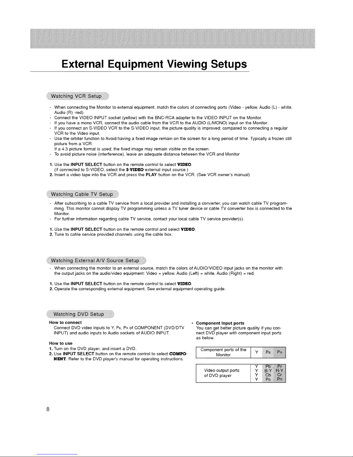
NOW to CoRRect
Connecl DVD video inputs to Y_ P_ P_ of COMPONENT (DVD/DTv'
INPUT) and audio inputs to Audio sockets of AUDIO INPUT,
Now to u_
1. Turn on the DVD player, and insert a DVD.
2. Use INPUT SELECT button on the remote control to seiect COMPO-
N_T. Refer to the DVD player's manua_ for operating instructions
• Component Input ports
You can get better picture quality if you con-
nect DVD player with component input ports
as below,
Component ports of the
Monitor
of DVD player
Video output ports

- Towatchdigitallybroadcastprograms,purchase/connectadigitalSET-TOPBOX,
How to connect a user-supplied Digital Set.Top Box
• Connect DTV set4op box video output to monitor COMPONENT (DVD/DTV iNPUT) or to the monffor RG81 (PC/DTV
iNPUT) connedor depending on your Set Top _x connectors
. Connect DTV set4op box audio outputs to monitor AUDIO INPUT jacks,
HOW tO use
1 Turn on the digita_ SET-TOP BOX, (Refer to the owner's ,manual for the digital SET-TOP BOX)
2 Use INPUT SELECT on the remote control to select COM_N£N't or R_ ].
To enjoy vivid picture and sound connect a PC to the Monitor,
Avoid keeping a fixed image on the monitor's screen for a tong period of time The fixed image may become permanent-
ty imprinted on the screen; use a screen saver when possible,
Connect PC to the RGBt INPUT(PC/DTV iNPUT) or RG82 INPUT(DIGiTAL RGB _NPUT) port of the Monitor; change the
resolution output of PC ac_rding_y.
Synchronization input form; Separate
Setup Instructions to Connect a PC to your Monitor
If the resolution of PC is over UXGA, there will be no picture on time Monitor.
Connect the signa_ cable from the monitor o_put port of the PC to the RGB1 INPUT(PG/DTV iNPUT) port of the Monitor
or the signal cable from the DVI output port of the PC to the RGB2 iNPUT(DIGITAL RGB iNPUT) port: on time Monitor.
Connect the audio _ble from the PC to the Audio input on the Monitor. (Audio cables are not included with the Monitor).
[f using a sound card adjust PC sound as required
This monitor _p_y a VESA Plug and Play Solution. The monitor provides EDID data to the PC system with a DDC proto-
col. The PC adjusts automatically to use this monitor.
DDC protocol is preset for RG81 (Anatog RGB) RG82 (DV[ Digital RGS) mode.
[f required adiust the monitor settings for Plug and Piay functionally.
- [f gr_hic card on the PC does not output analog and digital RGB simultaneously, connect only one of both RGBt iNPUT
(PC/DTV iNPUT) or RGB2 _NPUT (D_GITAL RGB iNPUT) to display the PC on the monitor.
If graphic card on the PC does OL_put analog and digital RG8 simultaneously set the monitor to either RG81 or RGB2;
(the other mode is set to Plug and Play automatically by the monitoQ
The monffor perceives 640x480, 60Hz as DTV 480p based on the PC graphic card. [n this case change the screen scan-
ning rate for the graphic card,
PC Setup
1. Turn on the PC and apply power to the Monffor,
2. Turn on the display by pressing the POWER button on the Monitor's remote control
3. Use the iNPUT SELECT button on the remote contro_ to select the RGB1 or RGB2 input source
4, Set the resolution output of the PC to SXGA or un_r (1280 x 1024, 75Hz),

RGB1 Mode
Resolution
640x350
720x400
640x480
800x600
RGB2 Mode
Resolution
_0x350
720x400
640x480
800x600
Horizontal;
Frequency(KHz)
31,468
37,86i
31.469
37_927
31.469
35.000
37.861
37,500
43,269
45,9i3
5&0ti
64.062
35.156
37.879
46..875
53.674
5&000
64.016
Horizontal
Frequency(KHz)
31.468
37.861
3i.469
37.927
31.469
35.000
37.86i
37.500
43.269
35.156
37_879
48.077
4&875
53.674
Vertical
Frequency(Hz)
70,09
85,08
70.08
8&03
59,94
66 66
72_80
7500
85.00
90, 03
10&04
12&00
56 25
8031
7500
8&06
90.00
10&00
VeHical
Frequency(Hz)
7&09
8&08
70,08
85,03
59,94
86,66
72,80
75,00
85_00
56.25
60.31
72.18
75.00
85.06
DDC
DDC
Reso|ution
832x624
Horizonta_
Frequency(KHz)
49,725
48,363
1024x768
o
o
o
1152x864
o
o
1152x870
! 280x960
1280x 1024
o
o
o
o
Resolution Frequency(KHz) Frequency(Hz)
5&476
60.023
88,677
54,348
6&995
87.500
77,487
68,68i
7&000
63.981
79.976
Horizontal Medical
832x624 49.725 74.55
4&363 60.00
o
1024x768
0
o
o
1152x864
o
o
o
1152x870 68.681 75.06
o
1280x960
o
1280x1024 6&981 60.02
o
0
56.476 70°06
60.023 75.02
6&677 84.99
54.348 60.05
6&995 70.01
67.500 75.00
77.487 85.05
60_000 60.00
75.000 7&00
Ve_lcai
Frequency(Hz)
74,55
60.00
7&06
75,02
84.99
60.05
70.01
75_00
8&05
7&06
75.00
60.02
75.02
DDC
o
o
o
o
o
o
o
o
o
o
o
o
o
DDC
o
o
o
o
o
o
o
o
o
o
e
o
o
Notes:
• DOS mode may not work depending on video card if using a DVH cable
• There might be a nois_ accordin£ to any resomution, conlrast, or bright:hess in PC mode Then change the PC
mode into other resolution or adiust brightness and cor_rast on the menu until file picture is clean.
10
 Loading...