

LG MU-42PM11, MU-50PM10, MU-42PM12X, MU-42PM20, MU-50PM11 User Manual
...
PLASMA MONITOR
OWNER’S MANUAL
Please read this owner’s manual thoroughly before operating
the Monitor.
Retain it for future reference.
Record model number and serial number of the Monitor.
See the label attached on the back of the Monitor and relate
this information to your dealer if you ever require service.
Model Number :
Serial Number :
MODELS : MU-42PM11/12X/20
MU-50PM10/11/20
LG Electronics U.S.A., Inc.
2 Plasma Monitor
Warning/Caution
WARNING/CAUTION:
TO REDUCE THE RISK OF ELECTRIC SHOCK DO NOT REMOVE COVER (OR BACK). NO USER
SERVICEABLE PARTS INSIDE. REFER TO QUALIFIED SERVICE PERSONNEL.
The lightning flash with arrowhead symbol, within an equilateral triangle, is intended to alert the user to
the presence of uninsulated “dangerous voltage” within the product’s enclosure that may be of sufficient magnitude to constitute a risk of electric shock to persons.
The exclamation point within an equilateral triangle is intended to alert the user to the presence of
important operating and maintenance (servicing) instructions in the literature accompanying the appliance.
WARNING/CAUTION:
TO PREVENT FIRE OR SHOCK HAZARDS, DO NOT EXPOSE THIS PRODUCT TO RAIN OR MOISTURE.
FCC NOTICE
• A Class B digital device
This equipment has been tested and found to comply with the limits for a Class B digital device, pursuant to Part
15 of the FCC Rules. These limits are designed to provide reasonable protection against harmful interference in
a residential installation. This equipment generates, uses and can radiate radio frequency energy and, if not
installed and used in accordance with the instructions, may cause harmful interference to radio communications.
However, there is no guarantee that interference will not occur in a particular installation. If this equipment does
cause harmful interference to radio or television reception, which can be determined by turning the equipment off
and on, the user is encouraged to try to correct the interference by one or more of the following measures:
- Reorient or relocate the receiving antenna.
- Increase the separation between the equipment and receiver.
- Connect the equipment into an outlet on a circuit different from that to which the receiver is connected.
- Consult the dealer or an experienced radio/TV technician for help.
• Any changes or modifications not expressly approved by the party responsible for compliance could void the user’s authority to operate the equipment.
CAUTION:
Do not attempt to modify this product in any way without written authorization from LG Electronics. Unauthorized modification could void the user’s authority to operate this product.
COMPLIANCE:
The responsible party for this product’s compliance is:
LG Electronics U.S.A., Inc
1000 Sylvan Avenue, Englewood Cliffs, NJ 07632
1-201-816-2000
http://www.lgusa.com
WARNING
RISK OF ELECTRIC SHOCK
DO NOT OPEN
/CAUTION
WARNING/CAUTION
TO REDUCE THE RISK OF FIRE AND ELECTRIC SHOCK, DO NOT EXPOSE THIS PRODUCT TO
RAIN OR MOISTURE.
W
W
arning/Caution
arning/Caution

Owner’s Manual 3
Warning/Caution
Important safeguards for you and your new product
Your product has been manufactured and tested with your safety in mind. However, improper use can result in potential electrical shock or fire hazards. To avoid defeating the safeguards that have been built into your new product, please read and
observe the following safety points when installing and using your new product, and save them for future reference.
Observing the simple precautions discussed in this booklet can help you get many years of enjoyment and safe operation
that are built into your new product.
This product complies with all applicable U.S. Federal safety requirements, and those of the Canadian Standards
Association.
1. Read these instructions.
2. Keep these instructions.
3. Heed all warnings.
4. Follow all instructions.
5. Do not use this apparatus near water.
6. Clean only with dry cloth.
7. Do not block any ventilation openings. Install in accordance with the manufacturer’s instructions.
8. Do not install near any heat sources such as radiators, heat registers, stoves, or other apparatus (including ampli-
fiers)that produce heat.
9. Do not defeat the safety purpose of the polarized or grounding-type plug. A polarized plug has two blades with
one wider than the other. A grounding type plug has two blades and a third grounding prong, The wide blade or the
third prong are provided for your safety. If the provided plug does not fit into your outlet, consult an electrician for
replacement of the obsolete outlet.
10. Protect the power cord from being walked on or pinched particularly at plugs, convenience receptacles, and the
point where they exit from the apparatus.
Safety Instructions
Safety Instructions
4 Plasma Monitor
Safety Instructions
11. Only use attachments/accessories specified by the manufacturer.
12. Use only with the cart, stand, tripod, bracket, or table specified by the manufacturer, or sold with the apparatus.
When a cart is used, use caution when moving the cart/apparatus combination to avoid injury from tip-over.
13. Unplug this apparatus during lightning storms or when unused for long periods of time.
14. Refer all servicing to qualified service personnel. Servicing is required when the apparatus has been damaged
in any way, such as power-supply cord or plug is damaged, liquid has been spilled or objects have fallen into the
apparatus, the apparatus has exposed to rain or moisture, does not operate normally, or has been dropped.
15. Outdoor Use Marking :
WARNING - To Reduce The Risk Of Fire Or Electric Shock, Do Not Expose This Appliance To Rain Or Moisture.
16. Wet Location Marking :
Apparatus shall not be exposed to dripping or splashing and no objects filled with liquids, such as vases, shall
be placed on the apparatus.
Safety Instructions continued
Safety Instructions continued
PORTABLE CART WARNING

Owner’s Manual 5
Safety Instructions
Contents
Contents
After reading this manual, keep it handy for future reference.
Warning/Caution . . . . . . . . . . . . . . . . . . . . . . . . . . . . . . . .2
Safety Instructions . . . . . . . . . . . . . . . . . . . . . . . . . . . . .3~4
Introduction
Controls . . . . . . . . . . . . . . . . . . . . . . . . . . . . . . .7
Connection Options . . . . . . . . . . . . . . . . . . . . . .8
Remote Control Key Functions . . . . . . . . . . . . . .9
Installation
Installation Instructions . . . . . . . . . . . . . . . . . .10~11
External Equipment Connections . . . . . . . . . .12~16
VCR Setup . . . . . . . . . . . . . . . . . . . . . . . . . . . .12
Cable TV Setup . . . . . . . . . . . . . . . . . . . . . . . .12
External A/V Source Setup . . . . . . . . . . . . . . . .13
DVD Setup . . . . . . . . . . . . . . . . . . . . . . . . . . . .13
DTV Setup . . . . . . . . . . . . . . . . . . . . . . . . . . . .14
PC Setup . . . . . . . . . . . . . . . . . . . . . . . . . .15~16
Operation
Turning on the Monitor . . . . . . . . . . . . . . . . . . . . .17
Menu Language Selection . . . . . . . . . . . . . . . . . .17
Picture Menu Options
APC (Auto Picture Control) . . . . . . . . . . . . . . . .18
XD . . . . . . . . . . . . . . . . . . . . . . . . . . . . . . . . . .18
Color Temperature Control . . . . . . . . . . . . . . . .18
Fleshtone . . . . . . . . . . . . . . . . . . . . . . . . . . . . .19
sRGB . . . . . . . . . . . . . . . . . . . . . . . . . . . . . . . .19
Manual Picture Control(Off option) . . . . . . . . . .19
Sound Menu Options
DASP (Digital Auto Sound Processing) . . . . . . .20
BBE . . . . . . . . . . . . . . . . . . . . . . . . . . . . . . . . .20
AVL (Auto Volume Leveler) . . . . . . . . . . . . . . . .20
Manual Sound Control (DASP set to Off option) . .21
Timer Menu Options
Clock Setup . . . . . . . . . . . . . . . . . . . . . . . . . . .22
On/Off Timer Setup . . . . . . . . . . . . . . . . . . . . .22
Auto Off / Sleep Timer . . . . . . . . . . . . . . . . . . .22
Special Menu Options
Key Lock . . . . . . . . . . . . . . . . . . . . . . . . . . . . .23
ISM (Image Sticking Minimization) Method . . . .23
Low Power . . . . . . . . . . . . . . . . . . . . . . . . . . . .24
XD Demo . . . . . . . . . . . . . . . . . . . . . . . . . . . . .24
Menu Rotation for Vertical Viewing . . . . . . . . . . .24
Screen Menu Options
Auto Adjustment . . . . . . . . . . . . . . . . . . . . . . .25
Setting Picture Format . . . . . . . . . . . . . . . . . . .25
Screen Position . . . . . . . . . . . . . . . . . . . . . . . .25
Manual Configure . . . . . . . . . . . . . . . . . . . . . .26
Selecting VGA Mode . . . . . . . . . . . . . . . . . . . . .26
Screen Adjustments . . . . . . . . . . . . . . . . . . . . .26
Cinema Mode Setup . . . . . . . . . . . . . . . . . . . . .26
Luminance Noise Reduction . . . . . . . . . . . . . . .27
Initializing (Reset to original factory value) . . . . .27
Split Zoom . . . . . . . . . . . . . . . . . . . . . . . . . . . .27
PIP (Picture-In-Picture)/Double Window Feature
Watching PIP/Double Window . . . . . . . . . . . . ..28
Swapping the PIP/Double Window . . . . . . . . . .28
Selecting an Input Signal Source for PIP/Double Window .
28
Moving the PIP(PIP Mode only) . . . . . . . . . . . .28
PIP Size . . . . . . . . . . . . . . . . . . . . . . . . . . . . . .28
PIP Transparency (PIP Mode only) . . . . . . . . . .28
External Control Device Setup . . . . . . . . . . . . . . . .29~34
IR Code Information . . . . . . . . . . . . . . . . . . . . . . .35~36
Troubleshooting Checklist . . . . . . . . . . . . . . . . . . . . . .37
Maintenance . . . . . . . . . . . . . . . . . . . . . . . . . . . . . . . . .38
Product Specifications . . . . . . . . . . . . . . . . . . . . . . . . .38
Warranty . . . . . . . . . . . . . . . . . . . . . . . . . . . . . . . . .39~40

6 Plasma Monitor
Introduction
Introduction
Introduction
What is a Plasma Display Panel (PDP)?
If voltage is applied to gas within glass panels, ultraviolet rays are produced and fused with a fluorescent substance. At that
instant, light is emitted. A Plasma Display is a next generation flat Display using this phenomenon.
160° - Wide angle range of vision
Your flat panel plasma screen offers an exceptionally broad viewing angle -- over 160 degrees. This means that the display is
clear and visible to viewers who can see the screen anywhere in the room.
Wide Screen
The screen of the Plasma Display is wide so that your viewing experience is as if you are in a theater.
Multimedia
Connect your plasma display to a PC and you can use it for conferencing, games, and internet browsing. The Picture-in-Picture
feature allows you to view your PC and video images simultaneously.
Versatile
The light weight and thin size makes it easy to install your plasma display in a variety of locations where conventional TVs would
not fit.
The PDP Manufacturing Process: Why minute colored dots may be present on the PDP screen
The PDP (Plasma Display Panel) which is the display device of this product is composed of 0.9 to 2.2 million cells. A few cell
defects will normally occur in the PDP manufacturing process. Several minute colored dots visible on the screen should be acceptable. This also occurs in other PDP manufacturers' products and the tiny dots appearing does not mean that this PDP is defective.
Thus a few cell defects are not sufficient cause for the PDP to be exchanged or returned. Our production technology is designed
to minimize cell defects during the manufacture and operation of this product.
Cooling Fan Noise
In the same way that a fan is used in a PC computer to keep the CPU (Central Processing Unit) cool, the PDP is equipped with
cooling fans to cool the Monitor and improve its reliability. Therefore, a certain level of noise could occur while the fans are operating and cooling the PDP.
The fan noise doesn't have any negative effect on the PDP's efficiency or reliability. The noise from these fans is normal during the
operation of this product. We hope you understand that a certain level of noise from the cooling fans is acceptable and is not sufficient cause for the PDP to be exchanged or returned.
Owner’s Manual 7
Introduction
Controls
Controls
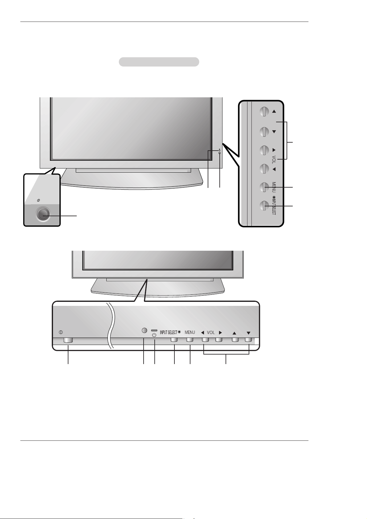
Front Panel Controls
Front Panel Controls
- This is a simplified representation of a typical front panel.
The Front Panel Controls shown here may be somewhat different from your monitor.
MU-42/50PM10/11 series
MU-42/50PM20 series
ON/OFF
ON/OFF
1
2
3 4 5 6
1
4
5
6
3
2
1. Main Power Button
2. Remote Control Sensor
3. Power Standby Indicator
Illuminates red in standby mode. Illuminates green when the
Monitor is turned on.
4. INPUT SELECT Button
5. MENU
Displays on screen menus one by one.
Exits the current menu.
Memorizes menu changes.
6.
DD/ EE
Selects a menu option.
FF/ GG
(Volume Up/Down)
Increases/decreases sound level.
Adjusts menu settings.
8 Plasma Monitor
Introduction
Connection Options
Connection Options
AC INPUT
AUDIO INPUT RGB OUTPUTRGB INPUTDVI INPUT
RS-232C INPUT
(CONTROL/SERVICE)
REMOTE
CONTROL
( )
( )
( )
( )
EXTERNAL SPEAKER
R
L
R
L
AUDIO INPUT
VIDEO INPUT
AUDIO INPUT
S-VIDEO
YPBP
R
(MONO)
COMPONENT INPUT
R
L
5
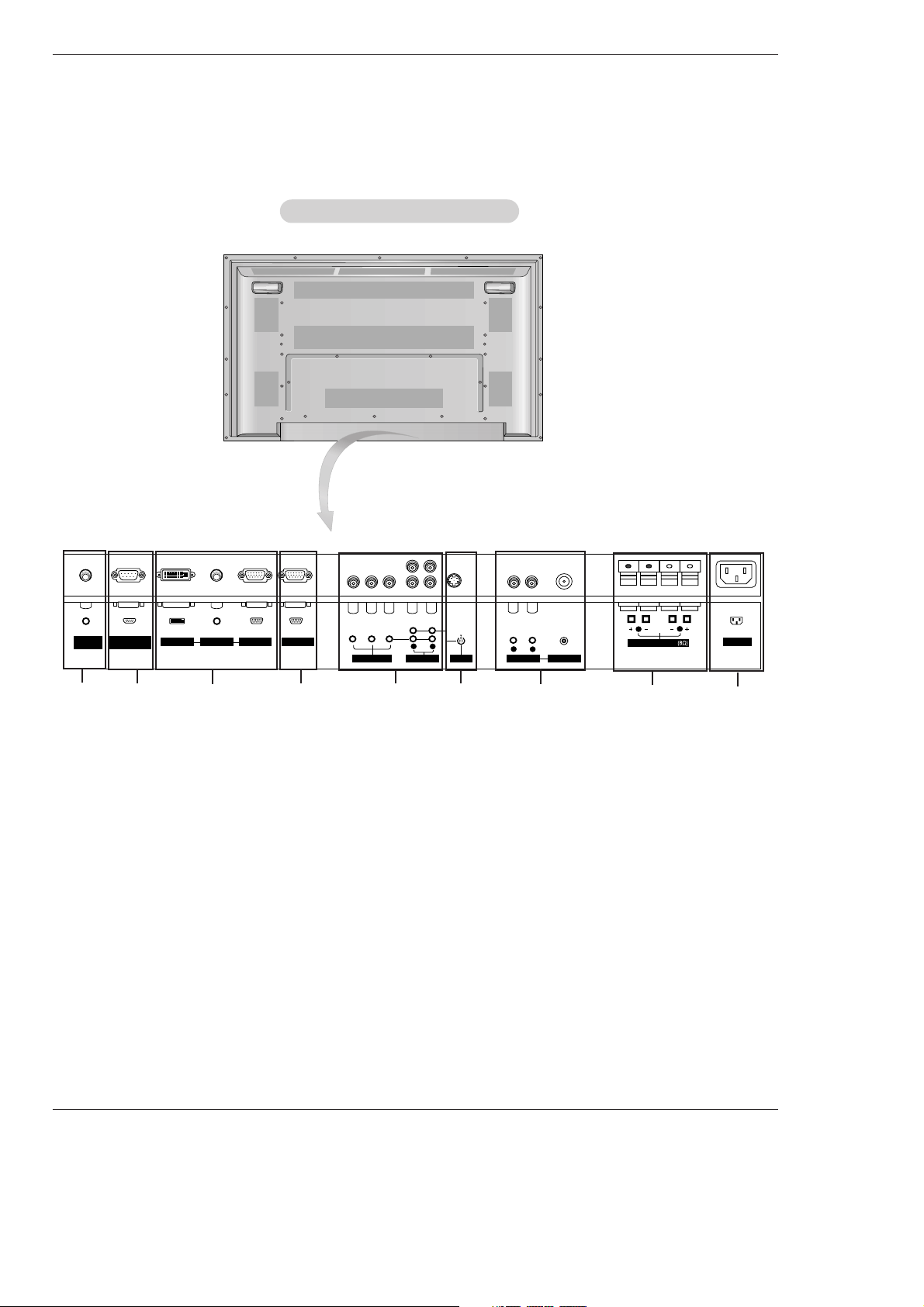
1. REMOTE CONTROL
Connect your wired remote control to the remote control
port on the Monitor.
2. RS-232C INPUT (CONTROL/SERVICE) PORT
Connect to the RS-232C port on a PC.
3. DVI (Digital Visual Interface) INPUT/
AUDIO INPUT/ RGB INPUT JACKS
Connect the monitor output connector from a PC to the
appropriate input port.
4. RGB OUTPUT PORT
You can watch the RGB signal on another monitor, connect
RGB OUTPUT to another monitor’s PC input port.
5. COMPONENT INPUT/AUDIO INPUT JACKS
Connect a component video/audio device to these jacks.
6. S-VIDEO INPUT SOCKETS
Connect S-Video out from an S-VIDEO device to the SVIDEO input.
NOTE: AUDIO INPUT of S-VIDEO is worked by L(mono).
7. VIDEO / AUDIO (L/MONO) INPUT SOCKETS
Connect audio/video output from an external device to
these jacks.
8. EXTERNAL SPEAKER (8 ohm output)
Connect to optional external speaker(s).
* For further information, refer to ‘Speaker & Speaker
Stand’ manual.
9. POWER CORD SOCKET
This Monitor operates on an AC power. The voltage is indicated on the Specifications page. Never attempt to operate
the Monitor on DC power.
Back Connection Panel
Back Connection Panel
1
3
4
2
8
6
9
7
- Connection panels shown may be somewhat different from your monitor.
Owner’s Manual 9
Introduction
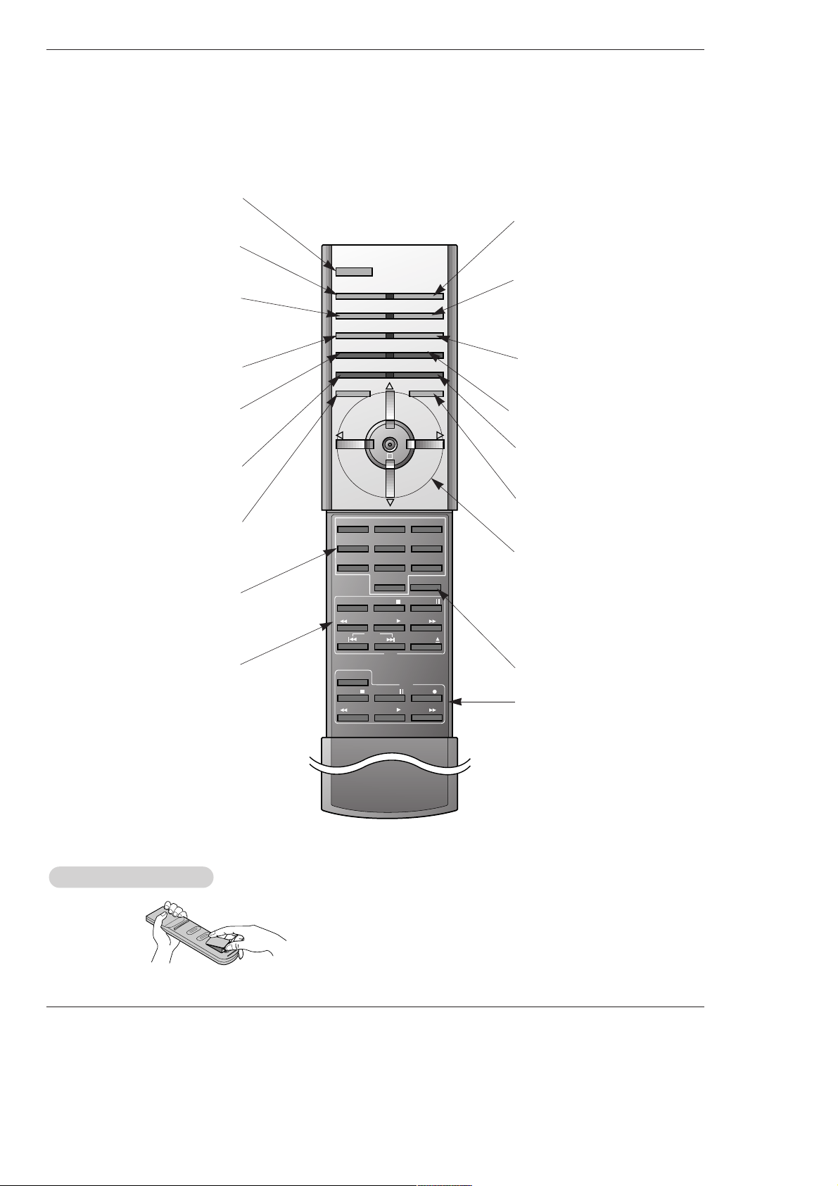
- When using the remote control, aim it at the remote control sensor on the monitor.
- Under certain conditions such as if the remote IR signal is interrupted, the remote control may not function. Press
the key again as necessary.
123
456
7809
POWER
SLEEP INPUT SELECT
APC DASP
ARC SPLIT ZOOM
PIP/DW
WIN.POSITION
SWAP
MENU MUTE
OK
VOL
POWER
REW
STOP
PLAY FF
REC
PAUSE
W
WIN.P
VOL
SUB INPUT
STOP P/STILL
REW
PLAY FF
POWER
VCR
DVD
OPEN/CLOSE
WIN.SIZE
SKIP
POWER
Switches the Monitor between
ON and STANDBY.
SLEEP
Sets the Sleep Timer.
(Refer to p.22)
APC
Adjusts the factory preset picture
according to the room.
(Refer to p.18)
ARC
Changes the picture format.
(Refer to p.25)
PIP/DW
Switches the sub picture on or off.
(Refer to p.28)
SWAP
Exchanges main and sub picture
images. (Refer to p.28)
MENU
Displays on screen menus one by one.
Exits the current menu.
NUMBER buttons
VCR BUTTONS
Control some video cassette
recorders.
OK
D / E
Selects menu option.
Memorizes menu changes.
F / G (Volume button)
Increases/decreases sound level.
Adjusts menu settings.
INPUT SELECT
Selects source:
RGB, DVI,
Component, Video, or S-Video
mode.
DASP
To select the sound appropriate to
your viewing program character:
Flat, Music, Movie, Sports, SRS
TSXT
or Off (Refer to p.20)
SPLIT ZOOM
Enlarges the picture.
SUB INPUT
Selects the input source for the sub
picture.
MUTE
Switches the sound on or off.
WIN.POSITION
Moves the sub picture.
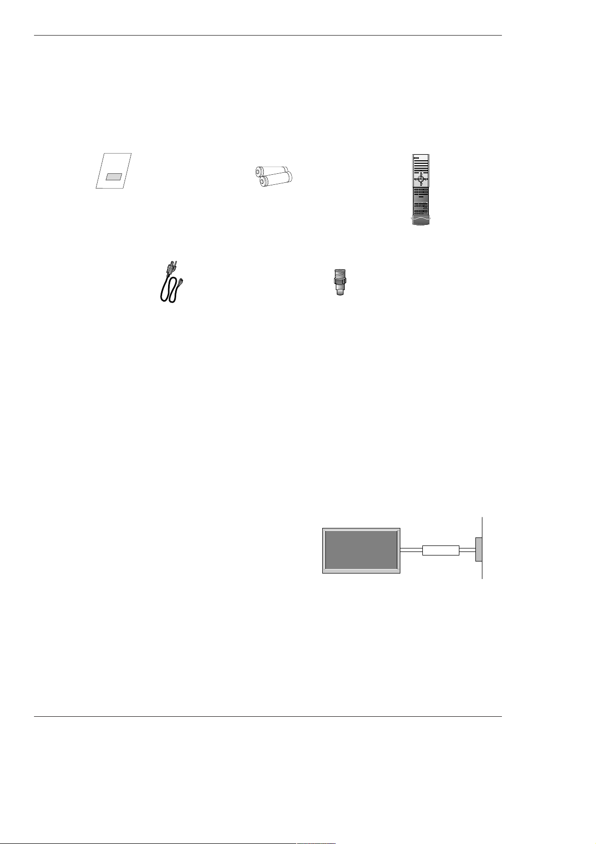
• Open the battery compartment cover on the back side and
insert the batteries with correct polarity.
• Install two 1.5V alkaline batteries of AAA type. Don’t mix used
batteries with new batteries.
Installing Batteries
Installing Batteries
Remote Control Key Functions
Remote Control Key Functions
DVD
Control some DVD cassette
recorders.
WIN.SIZE
Adjusts the sub picture size.
10 Plasma Monitor
Installation
Installation
Installation
Owner’s Manual
1.5V
1.5V
Alkaline Batteries
Power Cord
Ensure that the following accessories are included with your plasma display. If an accessory is missing, please contact the dealer
where you purchased the product.
Installation Instructions
Installation Instructions
• The Monitor can be installed in various ways such as on a wall, or on a desktop etc.
• The plasma display is designed to be mounted horizontally or vertically. The speakers shown are optional.
GROUNDING
Ensure that you connect the grounding / earth wire to prevent possible
electric shock. If grounding methods are not possible, have a qualified
electrician install a separate circuit breaker. Do not try to ground the
unit by connecting it to telephone wires, lightening rods, or gas pipes.
Power
Supply
Short-circuit
Breaker
123
456
7809
POWER
SLEEP INPUT SELECT
APC DASP
ARC PIP ARC
PIP
TWIN PICTURE
SWAP
MENU MUTE
OK
VOL
POWER STOP
PLAY FF
REC
REW
P/STILL
WIN.SIZE
WIN.POSITION
ZOOM +
ZOOM -
SPLIT ZOOM
VOL
SUB INPUT
Remote Control
BNC-RCA Adapter
Owner’s Manual 11
Installation
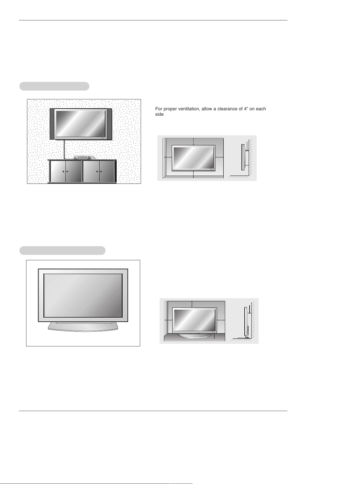
Desktop Pedestal Installation
Desktop Pedestal Installation
For proper ventilation, allow a clearance of 4” on each
side and the top, 2.36” on the bottom, and 2” from the
wall. Detailed installation instructions are included in the
optional Desktop Stand Installation and Setup Guide
available from your dealer.
Installation Instructions continued
Installation Instructions continued
WWall Mount Installation
all Mount Installation
For proper ventilation, allow a clearance of 4” on each
side and 2” from the wall. Detailed installation instructions are available from your dealer, see the optional
Wall Mounting Bracket Installation and Setup Guide.
4 inches
4 inches
2 inches
4 inches4 inches
4 inches
4 inches
4 inches
2.36 inches
2 inches
12 Plasma Monitor
Installation
NOTE: All cables shown are not included with the Monitor
- To avoid picture noise (interference), leave an adequate distance between the VCR and monitor.
- Use the ISM Method (on the Option menu) feature to avoid having a fixed image remain on the screen for a long period of time.
Typically a frozen still picture from a VCR. If the 4:3 picture format is used; the fixed images on the sides of the screen may
remain visible on the screen.
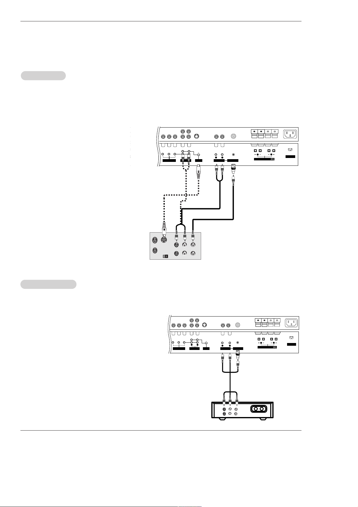
Connection Option
1. Connect the provided BNC-RCA adapter to the
monitor’s VIDEO INPUT.
2. Connect the audio and video cables from the
VCR's output jacks to the monitor input jacks,
as shown in the figure.
When connecting the monitor to VCR, match
the jack colors (Video = yellow, Audio Left =
white, and Audio Right = red).
If you connect an S-VIDEO output from VCR to
the S-VIDEO input, the picture quality is
improved; compared to connecting a regular
VCR to the Video input.
3. Insert a video tape into the VCR and press
PLAY on the VCR. (Refer to the VCR owner’s
manual.)
4. Select the input source with using the INPUT
SELECT button on the remote control. (If connected to VIDEO INPUT, select Video input
source)
VCR Setup
VCR Setup
AC INPUT
RGB OUTPUTINPUT
S-VIDEO
OUT
IN
(R) AUDIO (L) VIDEO
R
L
R
L
AUDIO INPUT
VIDEO INPUT
AUDIO INPUT
S-VIDEO
YPBP
R
(MONO)
COMPONENT INPUT
( )
( )
( )
( )
EXTERNAL SPEAKER
R
L
- After subscribing to a cable TV service from a local provider and installing a converter, you can watch cable TV programming.
The TV cannot display TV programming unless a TV tuner device or cable TV converter box is connected to the TV.
- For further information regarding cable TV service, contact your local cable TV service provider(s).
Connection Option
1. Connect the provided BNC-RCA adapter to the monitor’s VIDEO
INPUT.
2. Connect the audio and video cables from the Cable Box's output
jacks to the TV input jacks, as shown in the figure.
When connecting the TV to a Cable Box, match the jack colors
(Video = yellow, Audio Left = white, and Audio Right = red).
3. Select the input source with using the INPUT SELECT button on
the remote control. (If connected to VIDEO INPUT, select Video
input source)
4. Select your desired channel with the remote control for cable
box.
Cable
Cable
TV Setup
TV Setup
TV
VCR
RF Cable
(R) AUDIO (L) VIDEO
AC INPUT
R
L
R
L
AUDIO INPUT
VIDEO INPUT
AUDIO INPUT
S-VIDEO
YPBP
R
(MONO)
COMPONENT INPUT
( )
( )
( )
( )
EXTERNAL SPEAKER
R
L
VCR
Cable Box
External Equipment Connections
External Equipment Connections
 Loading...