

LG MU-42PZ44-AALZKZ Owner’s Manual

Instollotion ond Operoting 6uide
Model Number I P42W24Bx I PLASHA DISPLAY PANEL
e
C Copylght 2(}03, Zerii_ll _cttoncs
zenith
Warning
s
rnIn
WARNING
WARNING"
TO REDUCE THE RISK OF ELECTRIC SHOCK DO NOT REMOVE COVER (OR BACK) NO USER
SERVICEABLE PARTS _NSIDE. REFER TO QUALIFIED SERVICE PERSONNEL.
the presence of uninsu_ated dangerous voltage" w_bin tile product's enclosure that may be of suffi-
The lightning flash with arrowhead symbol, within an _uilateral triangle is intended to alert the user to
cient magn_ude to const_ate a risk of et_ric shock to persons.
The exclamation poinl within an equi_atera{ tfi_gle is intended to alert the user to the presence of
important operating and maintenance (servicing) instructions in the literature eccomp_ying the appli-
ance
WARNING
TO PREVENT FiRE OR SHOCK HAZARDS, DO NOT EXPOSE THIS PRODUCT TO RAIN OR MOISTURE.
FCC NOTICE
• A Class B digital device
This equipment has been tested and found to comply with the iimits for a Class B digital device, pursuant to Part
15 of the FCC Ru_es. These limits are designed to provide reasonable protect:ion against harmful interference in
a residential installation. This equipme_ generates, uses and can radiate radio frequency energy and, if not
inc4alled and used in accordance with the instructions, may cause harmfu_ interference to radio communications.
However, tllere is no guarantee that interference will not occur in a particular installation, if this equipment does
cause harmful interference to radio or television reception, whid-_ can be determined by turning the equipment off
and on the user is encouraged to try to correct the interference by one or more of the following measures:
- Reorient or relocate the receiving antenna
- _ncrease the separation between the equipment and receiver.
- Conned the equipment into an outlet on a circuit different from that to which the receiver is connected.
- Consult the dealer or an experienced radio/TV technician for help
• Any changes or modifications not expressly approved by the party responsible for compli-
ance could void the user's authority to operate the equipment.
CAUTION:
Do not attempt to modify tills product in any way w_hout written m,_horization from Zenith Electronics
Corporation. Unauthorized modification could void the user's aut:hor_y to operate this product
COMPLIANCE:
The responsible party for this product's compliance is:
Zenith Electronics Corporation
2000 MiHbrook Drive
Lincolnshire, 1160069 USA
Phone: 1-847-941 8000
WARNING
TO REDUCE THE RISK OF FIRE AND ELECTRIC SHOCK, DO NOT EXPOSE THIS PRODUCT TO
RAIN OR MOISTURE.
2 Pl_ma Display
SafetyInstructions
Important safeguards for you and your new product
"four product has been manufactured and tested with your safety in mind However_ improper use can result in potential elec-
trical shock or fire hazards To avoid defeating the _feguards that have been built into your new product, please read and
obse_e the following safety points wizen instaJ_ing and using your new product, and save them for future reference
Observing the simpie precautions discussed in this booklet can he_p you get many years of enjoyment and safe operation
that are built into your new product.
This product complies with a{I applicable US Federal safety requirements, and those of the Canadian Standards
Association.
1, Read Instructions 9. Attachments
AMI the safety and operating instructions should be read Do not use attachments not recommended by the product
before the product is operated manufacturer as they may cause hazards.
2. Follow Instructions
A_I operating and use instructions should be felmowed.
3, Retain instructions
The safety and operating instructions should he retained for
future reference.
4, Heed Warnings
A_Iwarnings on the product and in the operating instructions
should be adhered to.
5. Cleaning
UnpEug this product from the wall outlet before denning Do
not use liquid cleaners or aerosol c_eaners Use a _mp
clotl_ for cleaning
& Water and Moisture
Do not use this preduct near water, for exampte, near a bath
tub wash bowf kitchen sink or laundry tub in a wet base-
merit or near a swimming poet.
7, Accessories, Carts, and Stands
Do not place this product on a slippery or fitted surface, or on
an unstable cad, stand, tripod, bracket, or table. Tile product
may sEde or fuji, causing serious injury to a child or acUt,
and serious damage to the product Use only with a cad,
stud triped, bracket or table recommended by the manu
facturer, or sold with the product. Any mounting of the prod-
uct should fotlow time manufacturer's instructions, and should
use a mounting accessory recommended by the manufac-
turer.
8, Trans_rting Product
A product and cart combination should be moved with care.
Quick stops, excessive force, and uneven surfaces may
cause the product and cart cembin_ion to overturn.
10, Ventilation
Slots and openings in the cabinet are provi_d for ventilation
and to ensure reliable operation of the product and to protect
it from overheating, and these openings must not be blocked
or covered The openings should never be blocked by plac-
ing the product on a bed, sofa, rug, or other similar surface.
_is product shoutd not be placed in a buiitoin installation
suclm as a bookcase or rack unless proper ventimation is pro-
vided or the manufacturer's instructions have been adl_ered
11. Power Sources
This product should be operated only from the type of power
source indicated on the marking I_el. If you are not sure of
the type of power supply to your home consult your product
dealer or _ocal power company. For products i_ended to
operate from b_ery power, or other sources, refer to the
operating instructions
12. Power-Cord Polar}zation
This product is equipped with a three-wire grounding type
plug, a plug having a third (grounding) pin. This plug will onty
fit into the grounding-type power outlet. This is a safety fea-
ture. If you are unable to insert the plug into the outlet, con-
tact your electrici_ to replace your obsolete outlet Do not
defeat the safety purpese of time grounding4ype p_ug.
13. Power-Cord Protection
Power-supply cords should be routed so that they are not
likely to be walked on or pinched by items ptaced upon or
against them_ paying particular attention to cords at plugs
convenience receptacles, and the point where they exit from
the produd
POR_t_BLE CA_T WARN iN G
Owner's Manual 3
Safety Instructions
Instructions continued
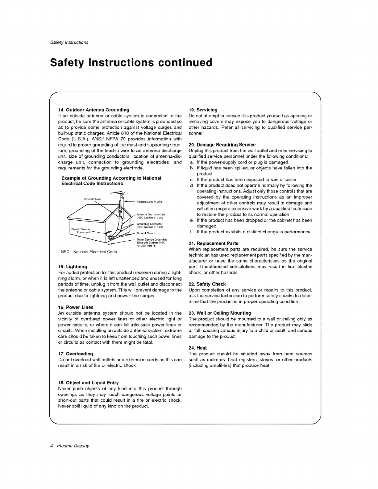
14, Outdoor Antenna Grounding
If an outside antenna or came system is connected to tt'_e
product, be sure timearrtenna or cable system is grounded so
as to provide some prot_ion against voltage surges and
built-up static charges. Adic[e 810 of the National Electrical
Code (U.SA.), ANSi/ NFPA 70 provides information w_h
regard to proper grounding of the mast and supporting struc-
ture, grounding of the lead4n wire to an antenna discharge
unit, size of grounding conductors location of antenna-dis-
charge unit connection to grounding electrodes and
r_uirements for the grounding electrode
Example ol Grounding A_ordtng to National
Eiect#_l Code Instructions
NEC Natohat EOectrica Code
15. Lightning
For added protection for this product (receiver) during a light-
ning storm, or when it is left unattended and unused for long
periods of time, unptug _ from the wall outlet and disconnect
the antenna or cable system. This will prevent damage to the
product due to lightning and powertine surges.
16, Power Lines
An outside antenna system should not be located in the
vicinity of overt_ead power lines or other el_ric tight or
power circuits, or where it can fall into such _wer lines or
circuits, When inst_ling an outside antenna system, extreme
care should be taken to keep from touching such power lines
or drcuits as contact with them might be fatal,
17, Overloading
Do not overload wall o_tets and extension cords as this can
result in a risk of fire or eleciric shock
19, Servicing
Do not attempt to service this product yourself as opening or
removing covers may expose you to dangerous voltage or
otller hazards Refer all servicing to qua_ifi_ service per
sonne[
20. Damage Requiring Service
Unplug this produc_ from the wa_ outtet and refer servicing to
qualified service personne_ under tt_e fo_owing conditions:
a. tf the power-supply cord or p_ug is _maged,
b. if _iquid has been spi_led, or objects have fallen into the
product
c. tf the product has been exposed to rain or water.
d. if the produ_ does not operate normally by following the
operating instructions. Adjust only those controls that are
covered by the operating instructions as an improper
adjustment of other controls may result in damage and
will often require extensive work by a qualified technician
to restore the product to its norma_ operation,
e, tf the product has been dropped orthe cabinet has been
damaged.
f. if the product exhibits a distinct change in performance
21, Replacement Parts
When replacement parts are required, be sure the service
tecl_nician has used replacement parts specified by the man-
ufacturer or have the same characteristics as the odginal
part Unauthorized substitutions may result in fire electdc
shock, or other hazards
22, Safety Check
Upon completion of any service or repairs to this product,
ask the service technician to perform safety checks to deter-
mine that the product is in proper operating condition
23. Wall or Ceiling Mounting
The product should be mounted to a wall or ceiling only as
recommended by the manufacturer. The product may slide
or fall, causing serious iniury to a child or adult, and serious
damage to time product
24, Heat
Time product should be situated away from heat sources
such as radiators, heat registers, stoves, or other products
(including amplifiers) that produce heat.
18, Object and Liquid Entry
Never push obiects of any kind into this product through
openings as they may touch dangerous voltage points or
shortoo_ parts that could result in a fire or electric shock.
Never spi[_liquid of any kind on the product
4 Plasma Display

Conten_s
Warnings ...................................... 2
Safety Instructions ............................ 3.°4
introduction
Controls _d Connection Options ........... 7
Remote Control Key Functions ............... 8
Installation
Installation Instruction .................... 9_10
Externa_ Equipment Connections ........ 11 --14
VCR Setup ...................... 11
Cabte TV Setup ........................ 11
Externai/VV Source Setup .................. 12
DVD Setup ............................... 12
DTV Setup ........................ 12
PC Setup ............................ 13-_14
Operation
Turning on time Monitor ................. 15
Menu Language Selection ................... 15
Video Menu Options
APC (Auio Picture Control) .......... 16
Manual Picture Contro[ ............... 16
Auto Color Temperature Controt ............ 16
Manual Color Temperature Control ......... 16
Audio Menu Options
DASP (Digitat Auto sound Processing) ..... 17
AVL (Auto Volume Leveler) ............. 17
Manual Sound Control ................ 17
Time Menu Options
Setting the Clock ....................... 18
Setting the On/Off _mer .................. 18
Auto Off ............................. 18
Sleep _mer ........................... 18
Special Menu Options
Key Lock ............................. 19
ISM (image Sticking Minimization)Method .... 19
Low power ........................ 19
Screen Menu Options
Auto Adjustment ........................ 20
SettingPicture Format ............... 20
Picture Size Zoom ................... 20
Adjusting Hodzonta[/VeMica[ Position .........21
Manual Configure ....................... 21
Screen Adjustments ................. 21
initializing ............................... 2t
Lumin_ Noise Reduction ............... 22
Selecting Wide VGA m_e ................ 22
Split Zoom ........................... 22
PIP (Picture _n Picture) Fe_ure
Watching PIP ............................. 23
PIP Size ................................. 23
Moving PIP ............................. 23
Swapping PIP .......................... 23
Selecting a Input Signal Source for PIP ....... 23
P IP Aspect Ratio ........................ 23
Double Window Setup Options
Watching Doubie Window ................. 24
Sub Picture Size Adjustment ............ 24
Swapping the Double Window .......... 24
Selecting a source for the Double Window 24
External Control Device Setup ................ 25_30
IR Code (NEC format) ....................... 31--32
Troubleshooting Checklist ...................... 33
Maintenance ................................. 34
Specifications .................................. 35
After reading this manual, keep it handy for future reference.
Owner's Manual 5
Introduction
What is a Plasma Displiay Panel (PDP)?
If voffage is applied to gas within glass panels ultraviolet rays are produced and fused with a fluorescent substance At that
instant, light is emitted A Plasma Display is a next generation fiat Display using this phenomenon,
160 ° - Wide angle range of vision
Your fiat panel plasma screen offers an exceptionaiBybroad viewing angle °_over 160 degrees, This means that the display is
clear and visible to viewers anywhere in the room.
Wide Screen
The screen of tile Plasma Display is 42" so wide that your viewing experience is as if you are in a theater_
Multimedia
Connect your plasma display to a PC and you can us it for conferencing games _d internet browsing The Picture-in-Picture
feature atJowsyou to view your PC and video images simultaneously,
Versatile
The _ightweight and thin size makes it easy to installyour ptasma display in a variety of tocations where conventiona_ TVs wiiQnot
fit,
The PDP Manufacturing Process: Why minute colored dots may be present on the PDP screen
The PDP (PJasma Display PaneO which is the display device of this product is composed of 0.9 to 2,2 million celts Afew cell
defects wi[_ normatEy occur in the PDP manufacturing process. SeveraJ minute coUored dots visible on the screen should be accept-
able, This also occurs in other PDP manufacturers' products and the tiny dots appearing does not mean that this PDP is defective,
Thus a few ceil defects are not sufficient cause for the PDP to be exchanged or returned Our production technology is designed
to minimize celt defects during the manufacture and operation of this product
Cooling Fan Noise
in the s_e way that a fan is used in a PC computer to keep the CPU (Central Processing Unit) cool_ tl_e PDP is equipped w_h
cooling f_s to cool the Monitor and improve its reliabii_y Therefore a certain leve_ of noi_ couid occur while the fans are operat =
ing and cooming the PDP.
The fan noise deesn't have any negative effect on the PDP's efficiency or re{iability, The noise from these fans is normal dudng the
operation of this product, We hope you understand that a certain teve_ of noise from the cooling fans is acceptable and is not suffi-
cient cause for the PDP to be exchanged or returned,
6 Plasma Display
Inlroductien
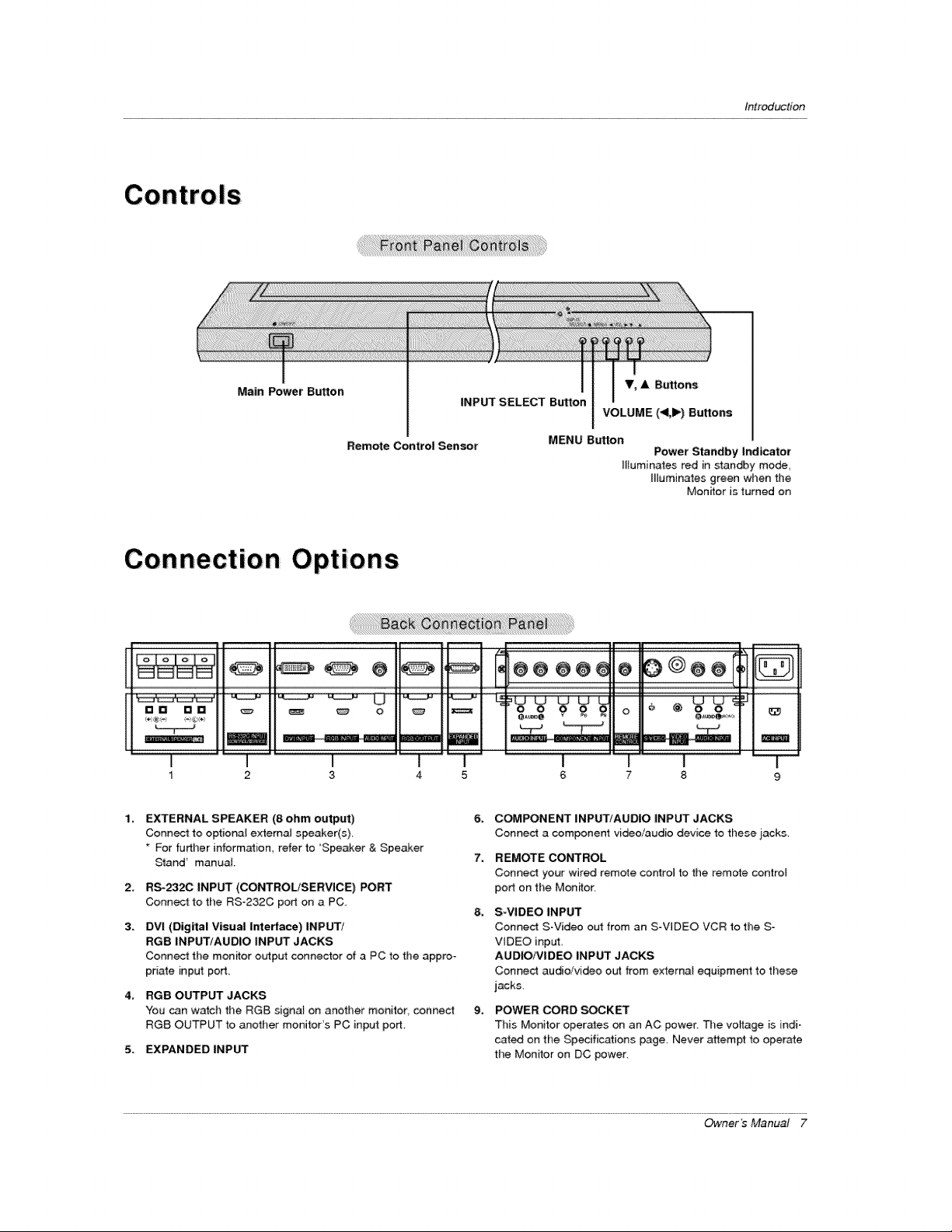
Main Power Button
Remote Control Sensor
Connection Options
[] [] [] D
I
1 2
EXTERNAL SPEAKER (8 ohm output)
Connect to optional external speaker(s)
* For further information, refer to 'Speaker & Speaker
Sland _ manual
2_
RS-_2C INPUT (COt',q'ROL/SERVICE) PORT
Connect to the RS-232C port on a PC,
3.
DVI (Digital Visual Interface) INPUT/
RGB INPUT/AUDIO INPUT JACKS
Connect the monitor output connector of a PC to fl_e appro-
priate input pod_
4_
RGB OUTPUT JACKS
You can watch the RGB signal on another monitor connect
RGB OUTPUT to another monitor's PC input port,
5. EXPANDED INPUT
_ o
3
V, A Buttons
INPUT SELECT Button
MENU Button
VOLUME (<1,1_) Buttons
Power Standby indicator
Illuminates red in standby mode
Illuminates green when the
Monitor is turned on
| __ _
1 I
4 5 6 7 8 9
6_
COMPONENT INPUT/AUDIO iNPUT JACKS
Connect a component video/audio device fotl)ese iacks,
7.
REMOTE CONTROL
Connect your wired remote control to the remote control
porton the Monitor,
8_
S-VIDEO INPUT
Connect S-Virteo out from an SoVIDEO VCR to the S-
VIDEO input,
AUDIO/VIDEO iNPUT JACKS
Connect audio/video out from externat equipment to these
jack&
9_
POWER CORD _KET
This Monitor operates on an AC power. The voltage is indi-
cated on the Specifications page, Never attempt fo operate
the Monitor on DC power.
Owner's Manual 7
Introduction
Remote Control Key Functions
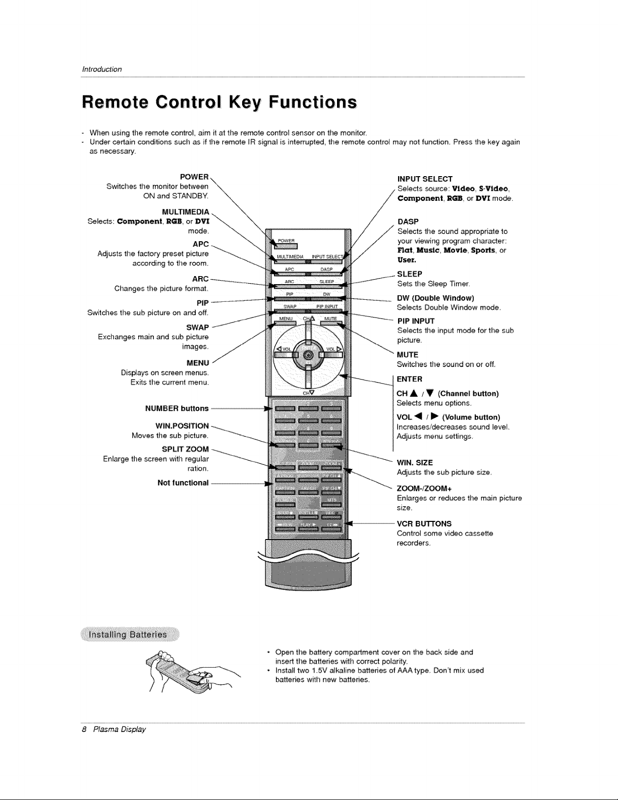
When using the remote control, aim it at the remote control sensor on the monitor.
Under certain conditions such as if the remote [R signal is interrupted, tile remote co.re[ may not function_ Press the key again
as necessary
Switches the monitor between
ON and STANDBY.
MULTIMEDIA
Setects: Component, RGB, or DVI \\-_
mode
Adjusts the factory preset picture
according to the room
Changes the picture format,
PiP
Switches the sub picture on and off,
SWAP
Exchanges main and sub picture
images,
MENU
Displays on screen menus.
Exits the current menu.
NUMBER buttons
Moves the sub picture.
Enlarge the screen with regutar
ration
Not functional
INPUT SELECT
Selects source: Video S-Video
Component, R_ or DVI mo_.
DASP
Se{eds the sound appropnate to
your viewing program character:
Flat Music, Mo_e Spo_s or
User.
SLEEP
Sets time Sleep Timer:
DW (Double Window)
Selects Double Window mode
PIP INPUT
Setects the input m_e for the sub
picture
MUTE
Sw_ches the sound on or off,
ENTER
OH A I _ (Channe| button)
Selects menu options
VOL <il / Jl_ {Volume button)
Increases!decreases sound level.
Adjusts menu settings
WIN. SiZE
Adjusts the sub picture size.
ZOOM-/ZOOM+
Enlarges or reduces the main picture
size.
VCR BUTI'ONS
Control some vi_o c_ssette
recorders
8 Pl_ma Display
• Open the battery compartment cover on the back side and
insert the bakeries with correct polarity.
• Install two 15V a_kaline batteries of AAA type Don't mix used
batteries with new batteries
tnstaltation
t
IOn
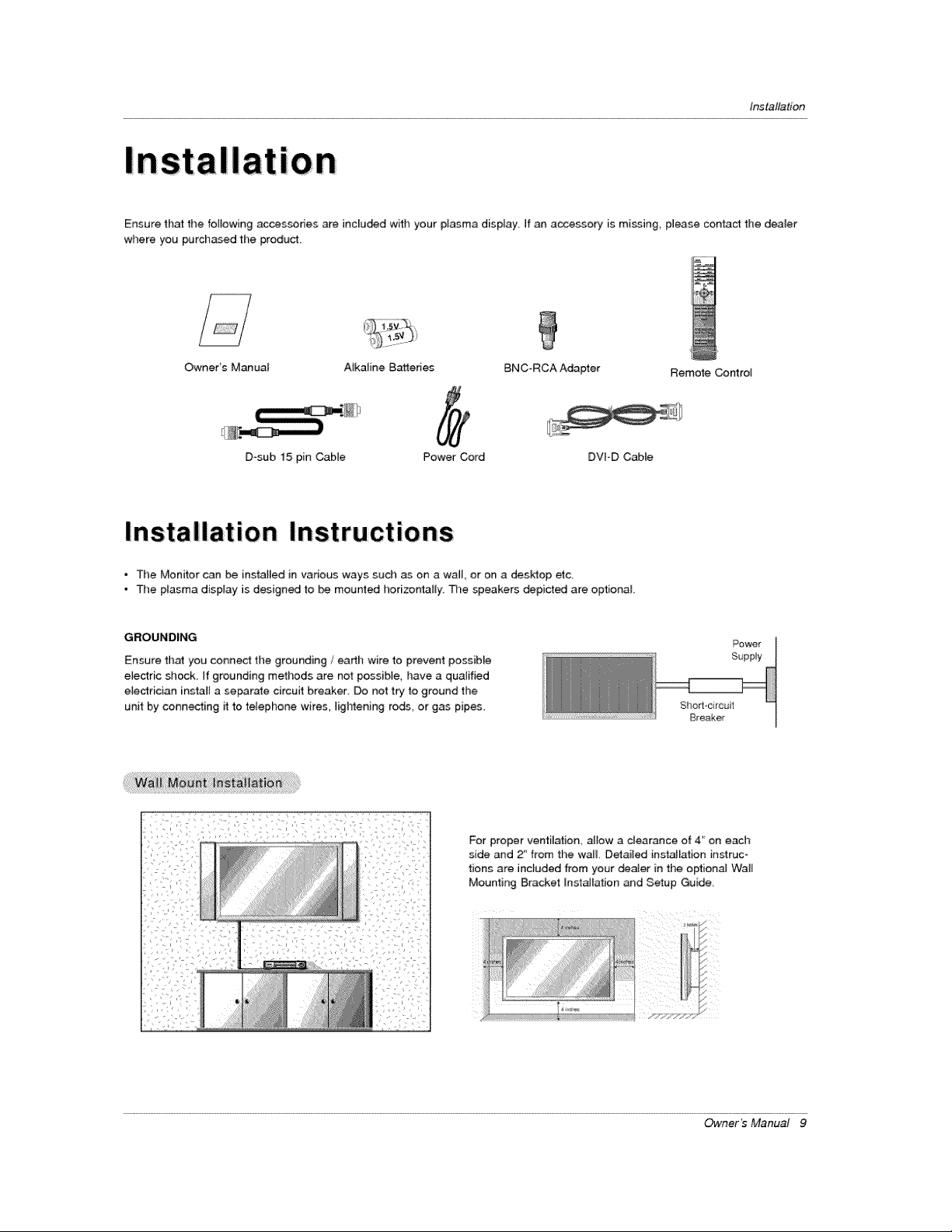
Ensure that the fo_lowincj accessories are included with your plasma display If an accessory is m[ssing_ please contact the dealer
where you purchased the product,
Owners Manual A_kaline Bakeries BNC-RCA Adapter Remote Control
D_sub 15 pin Cable Power Cord DVI-D Cable
* The Monitor can be installed in various ways such as on a wall, or on a desktop etc.
- The plasma display is designed to be mourned horizo_l[y. De speakers depicted are optional
GROUNDING
Ensure that you connect tl)e grounding / earth wire to prevent possiMe
eiectric shock. If grounding methods are net possible, have a qualified
electrician install a serrate circuit breaker Do not try to ground the
unit by conn_ing it to telephone wires, lightening rods or gas pipes
For proper ventilation allow a clearance of 4' on each
side and 2_from the wa& Detailed instalEation instruc-
tions are inctuded from your denier in the optional Wait
Mounting Bracket [nstaJiation and Setup Guide.
Power
Supply
Sho_l-circuit
Breaker
Owner's Manual 9
Installarion
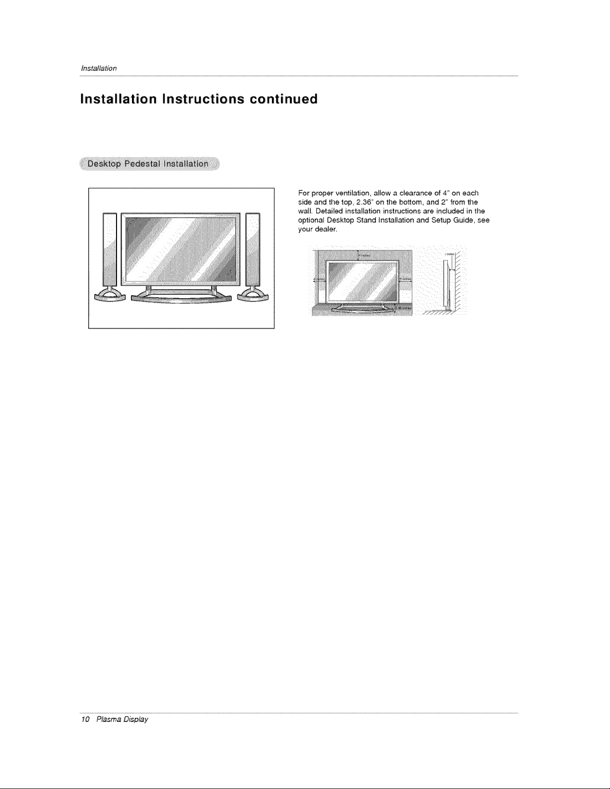
Installation Instructions continued
For proper ve_ilation, allow a clearance of 4" on each
side and the top, 2,36" on the bottom, and 2 _'from the
wa_L Detai_ed instalEation instructions are included in the
optiona_ Desktop Stand lnstaH_ion and Setup Gui_, see
your deaJer
10 P_sma D_p_y
tns_altation
External Equipment Connections
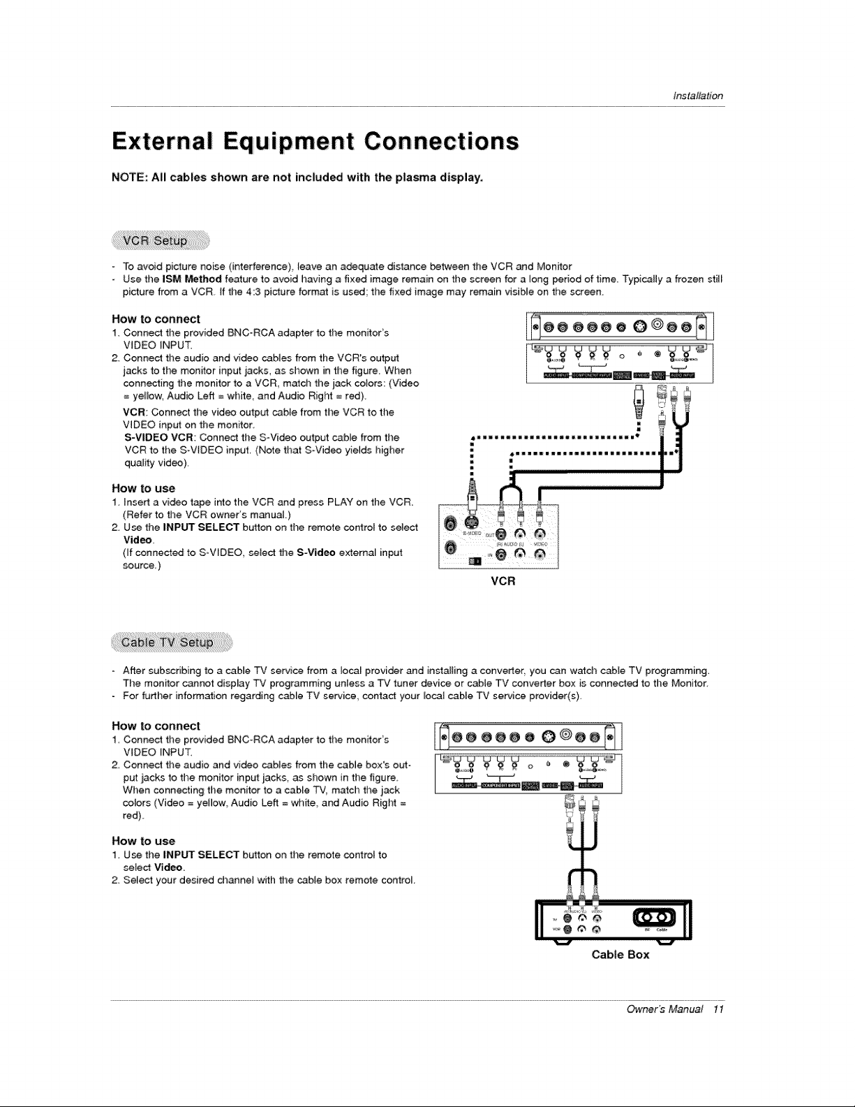
NOTE: All cables shown are not included with the plasma display.
- To avoid picture noise (interference), leave an adequate dis_nce between tile VCR and Monitor
Use the iSM Method feature to avoid having a fixed image remain on the screen for a]ong period of time Typically a frozen still
picture from a VCR. If the 4:3 picture format is used', tile fixed image may remain visible on the screen.
How to connect
1. Connect the provided BNC_RCA adapter to the monitor's
VIDEO _NPUT.
2 Connect time audio and video cables from the VCR's output
jacks to the monitor input jacks, as shown in the figure. When
connecting the monitor to a VCR, m_cb the jack cotors: (Video
= yellow, Audio Left = white, and Audio Rigt_ = red).
VCR: Connect the video output cable from time VCR to the
VIDEO input on the monitor.
S-VIDEO VCR; Connect time S-Video output cable from time
VCR to the S-VtDEO input. (Note that S-Video yields higher
quality video),
How to use
1 inset1 a video tape into the VCR and press PLAY on the VCR
(Refer to the VCR owner's manuaL)
2, Use the INPUT SELECT button on the remote cor4rol to select
Video,
(ff connected to S_V_DEO, select the S-Vid_ externa_ input
source_)
_II_IIItI11111111_II IItlIIII _
j*_@@ @@@ o 0 @@@_
Ii iiii iiin iiii iiii iiiiii I III I
VCR
- After subscribing to a cabme TV service from a local provider and installing a converter you can w_dt cable TV programming.
The monffor c_not display TV programming unless a TV tuner device or cabJe TV converter box is connected to the Monitor
For further information regarding cable TV service, contact your _ocal cabEe TV service provider(s),
How to conner
1 Connect the provided BNC_RCA adapter to time monitor's
VIDEO _NPUT.
2, Connect the audio and video _bles from the cable box's orb-t-
put iacks to the monitor input jacks, as shown in the figure.
Wimen connecting timemonitor to a cable TV, match the iack
cotors (Video = yetiow, Audio Left = white, and Audio Right =
red)
How to use
1, Use the INPUT SELECT button on the remote octroi to
select Video,
2, Sele_ your desired channel wffh the cable be× remote control
@@@@@O 0@@@®
iiiiiiii[8_'
Cable Box
Owner _ Manual 11
 Loading...