

LG MU-42PZ41Vx Service Manual

PLASMA MONITOR
OWNER’S MANUAL
MODELS : MU-42PZ41V
MU-42PZ41VA
MU-42PZ41VB
MU-42PZ41VK
MU-42PZ41VR
MU-42PZ41VS
Please read this owner’s manual carefully before operating the
Monitor.
Retain it for future reference.
Record model number and serial number of the Monitor.
See the label attached on the back of the Monitor and quote
this information to your dealer when you require service.
Model number :
Serial number :
P/NO : 3828VA0361C (RF02RA)
WARNING
WARNING
RISK OF ELECTRIC SHOCK
DO NOT OPEN
WARNING:
TO REDUCE THE RISK OF ELECTRIC SHOCK DO NOT REMOVE COVER (OR BACK). NO
USER SERVICEABLE PARTS INSIDE. REFER TO QUALIFIED SERVICE PERSONNEL.
The lightning flash with arrowhead symbol, within an equilateral triangle, is intended to alert the
user to the presence of uninsulated “dangerous voltage” within the product’s enclosure that may
be of sufficient magnitude to constitute a risk of electric shock to persons.
The exclamation point within an equilateral triangle is intended to alert the user to the presence
of important operating and maintenance (servicing) instructions in the literature accompanying
the appliance.
WARNING:
TO PREVENT FIRE OR SHOCK HAZARDS, DO NOT EXPOSE THIS PRODUCT TO RAIN OR MOISTURE.
FCC NOTICE
• A Class B digital device
This equipment has been tested and found to comply with the limits for a Class B digital device, pursuant
to Part 15 of the FCC Rules. These limits are designed to provide reasonable protection against harmful
interference in a residential installation. This equipment generates, uses and can radiate radio frequency
energy and, if not installed and used in accordance with the instructions, may cause harmful interference to
radio communications. However, there is no guarantee that interference will not occur in a particular installation. If this equipment does cause harmful interference to radio or television reception, which can be determined by turning the equipment off and on, the user is encouraged to try to correct the interference by one
or more of the following measures:
- Reorient or relocate the receiving antenna.
- Increase the separation between the equipment and receiver.
- Connect the equipment into an outlet on a circuit different from that to which the receiver is connected.
- Consult the dealer or an experienced radio/TV technician for help.
• Any changes or modifications not expressly approved by the party responsible for
compliance could void the user’s authority to operate the equipment.
WARNING
TO REDUCE THE RISK OF FIRE AND ELECTRIC SHOCK, DO NOT EXPOSE THIS PRODUCT TO
RAIN OR MOISTURE.
2
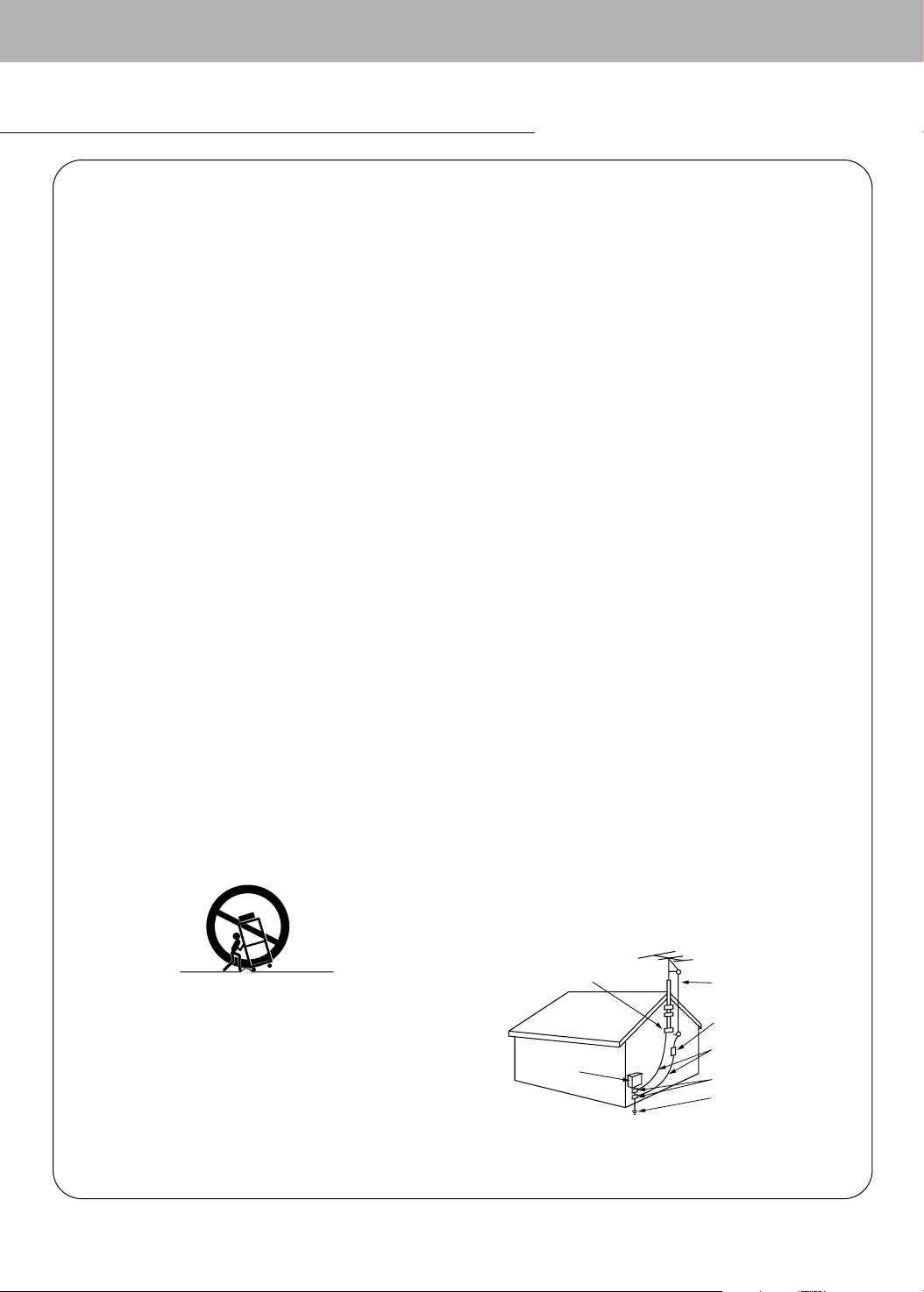
PORTABLE CART WARNING
SAFETY INSTRUCTIONS
Antenna Lead in Wire
Antenna Discharge Unit
(NEC Section 810-20)
Grounding Conductor
(NEC Section 810-21)
Ground Clamps
Power Service Grounding
Electrode System (NEC
Art 250, Part H)
Ground Clamp
Electric Service
Equipment
Important safeguards for you and your new product
Your product has been manufactured and tested with your safety in mind. However, improper use can result in potential electrical
shock or fire hazards. To avoid defeating the safeguards that have been built into your new product, please read and observe the
following safety points when installing and using your new product, and save them for future reference.
Observing the simple precautions discussed in this booklet can help you get many years of enjoyment and safe operation that are
built into your new product.
This product complies with all applicable U.S. Federal safety requirements, and those of the Canadian Standards Association.
1. Read Instructions
All the safety and operating instructions should be read before
the product is operated.
2. Follow Instructions
All operating and use instructions should be followed.
3. Retain Instructions
The safety and operating instructions should be retained for
future reference.
4. Heed Warnings
All warnings on the product and in the operating instructions
should be adhered to.
5. Cleaning
Unplug this product from the wall outlet before cleaning. Do not
use liquid cleaners or aerosol cleaners. Use a damp cloth for
cleaning.
6. Water and Moisture
Do not use this product near water, for example, near a bath tub,
wash bowl, kitchen sink, or laundry tub, in a wet basement, or
near a swimming pool.
7. Accessories Carts and Stands
Do not place this product on a slippery or tilted surface, or on an
unstable cart, stand, tripod, bracket, or table. The product may
slide or fall, causing serious injury to a child or adult, and serious
damage to the product. Use only with a cart, stand, tripod, bracket, or table recommended by the manufacturer, or sold with the
product. Any mounting of the product should follow the manufacturer’s instructions, and should use a mounting accessory
recommended by the manufacturer.
8. Transporting Product
A product and cart combination should be moved with care.
Quick stops, excessive force, and uneven surfaces may cause
the product and cart combination to overturn.
case or rack unless proper ventilation is provided or the manufacturer’s instructions have been adhered to.
11. Power Sources
This product should be operated only from the type of power
source indicated on the marking label. If you are not sure of the
type of power supply to your home, consult your product dealer
or local power company. For products intended to operate from
battery power, or other sources, refer to the operating instructions.
12. Power-Cord Polarization
This product is equipped with a three-wire grounding type plug,
a plug having a third (grounding) pin. This plug will only fit into
the grounding-type power outlet. This is a safety feature. If you
are unable to insert the plug into the outlet, contact your electrician to replace your obsolete outlet. Do not defeat the safety purpose of the grounding-type plug.
13. Power-Cord Protection
Power-supply cords should be routed so that they are not likely
to be walked on or pinched by items placed upon or against
them, paying particular attention to cords at plugs, convenience
receptacles, and the point where they exit from the product.
14. Outdoor Antenna Grounding
If an outside antenna or cable system is connected to the product, be sure the antenna or cable system is grounded so as to
provide some protection against voltage surges and built-up static charges. Article 810 of the National Electrical Code (U.S.A.),
ANSI/ NFPA 70 provides information with regard to proper
grounding of the mast and supporting structure, grounding of the
lead-in wire to an antenna discharge unit, size of grounding conductors, location of antenna-discharge unit, connection to
grounding electrodes, and requirements for the grounding electrode.
9. Attachments
Do not use attachments not recommended by the product manufacturer as they may cause hazards.
10. Ventilation
Slots and openings in the cabinet are provided for ventilation
and to ensure reliable operation of the product and to protect it
from overheating, and these openings must not be blocked or
covered. The openings should never be blocked by placing the
product on a bed, sofa, rug, or other similar surface. This product should not be placed in a built-in installation such as a book-
Example of Grounding According to National
Electrical Code Instructions
NEC - National Electrical Code
(Continued on next page)
3

SAFETY INSTRUCTIONS
(Continued from previous page)
15. Lightning
For added protection for this product (receiver) during a lightning
storm, or when it is left unattended and unused for long periods
of time, unplug it from the wall outlet and disconnect the antenna or cable system. This will prevent damage to the product due
to lightning and power-line surges.
16. Power Lines
An outside antenna system should not be located in the vicinity
of overhead power lines or other electric light or power circuits,
or where it can fall into such power lines or circuits. When
installing an outside antenna system, extreme care should be
taken to keep from touching such power lines or circuits as contact with them might be fatal.
17. Overloading
Do not overload wall outlets and extension cords as this can
result in a risk of fire or electric shock.
18. Object and Liquid Entry
Never push objects of any kind into this product through openings as they may touch dangerous voltage points or short-out
parts that could result in a fire or electric shock. Never spill liquid
of any kind on the product.
19. Servicing
Do not attempt to service this product yourself as opening or
removing covers may expose you to dangerous voltage or other
hazards. Refer all servicing to qualified service personnel.
20. Damage Requiring Service
Unplug this product from the wall outlet and refer servicing to
qualified service personnel under the following conditions:
a. If the power-supply cord or plug is damaged.
b. If liquid has been spilled, or objects have fallen into the prod-
uct.
c. If the product has been exposed to rain or water.
d. If the product does not operate normally by following the
operating instructions. Adjust only those controls that are
covered by the operating instructions as an improper adjustment of other controls may result in damage and will often
require extensive work by a qualified technician to restore
the product to its normal operation.
e. If the product has been dropped or the cabinet has been
damaged.
f. If the product exhibits a distinct change in performance.
21. Replacement Parts
When replacement parts are required, be sure the service technician has used replacement parts specified by the manufacturer or have the same characteristics as the original part.
Unauthorized substitutions may result in fire, electric shock, or
other hazards.
22. Safety Check
Upon completion of any service or repairs to this product, ask
the service technician to perform safety checks to determine that
the product is in proper operating condition.
23. Wall or Ceiling Mounting
The product should be mounted to a wall or ceiling only as recommended by the manufacturer. The product may slide or fall,
causing serious injury to a child or adult, and serious damage to
the product.
24. Heat
The product should be situated away from heat sources such as
radiators, heat registers, stoves, or other products (including
amplifiers) that produce heat.
The PDP Manufacturing Process: Why colored dots may be present on the PDP screen
The PDP (Plasma Display Panel) which is the display device of this product is composed of 0.9 to 2.2 million cells. A few cell
defects will normally occur in the PDP manufacturing process. Several colored dots visible on the screen should be acceptable. This also occurs in other PDP manufacturers' products and the dots appearing does not mean that this PDP is defective. Thus a few cell defects are not sufficient cause for the PDP to be exchanged or returned. Our production technology is
designed to minimize cell defects.
Cooling Fan Noise
In the same way that a fan is used in a PC computer to keep the CPU (Central Processing Unit) cool, the PDP is equipped
with cooling fans to cool the Monitor and improve its reliability. Therefore, a certain level of noise could occur while the fans
are operating and cooling the PDP.
This noise doesn't have any negative effect on the PDP's efficiency or reliability. The noise from these fans is normal during
the operation of this product. We hope you understand that a certain level of noise from the cooling fans is acceptable and is
not sufficient cause for the PDP to be exchanged or returned.
4

Contents
Warnings . . . . . . . . . . . . . . . . . . . . . . . . . . . . . . . . . . . . .2
Safety Instructions . . . . . . . . . . . . . . . . . . . . . . . . . . . . .3~4
Step 1. Monitor Installation & Setup
Controls and Connection Options . . . . . . . . . . . .6
External Equipment Connections . . . . . . . . . . . .7
External Equipment Viewing Setups . . . . . . .8~10
Remote Control Key Functions . . . . . . . . . . . . .11
Monitor Installation/Mounting Options . . . . . . . .12
Monitor Accessories . . . . . . . . . . . . . . . . . . . . .13
Step 2. Customize your Monitor’s Features
Basic Features Setup and Operation
Turning on the Monitor . . . . . . . . . . . . . . . . . . .14
Menu Language Selection . . . . . . . . . . . . . . . .14
Picture Menu Options
APC (Auto Picture Control) . . . . . . . . . . . . . . . .15
Manual Picture Control . . . . . . . . . . . . . . . . . . .15
Sound Menu Options
DASP (Digital Auto Sound Processing) . . . . . . .16
Adjusting Sound (Manual Settings) . . . . . . . . . .16
AVL(Auto Volume Leveler) . . . . . . . . . . . . . . . .16
Special Menu Options
Menu Rotation for Vertical Viewing . . . . . . . . . .17
Orbiter . . . . . . . . . . . . . . . . . . . . . . . . . . . . . . .17
White Wash . . . . . . . . . . . . . . . . . . . . . . . . . . .17
Sleep Timer . . . . . . . . . . . . . . . . . . . . . . . . . . .17
Adjusting Auto Color Control . . . . . . . . . . . . . . .18
Manual Color Temperature Control . . . . . . . . . .18
Key Lock . . . . . . . . . . . . . . . . . . . . . . . . . . . . .18
Screen Menu Options
Auto Adjustment . . . . . . . . . . . . . . . . . . . . . . . . 19
Adjusting Horizontal/Vertical Position . . . . . . . .19
Picture Phase Adjustments . . . . . . . . . . . . . . . .19
Initializing . . . . . . . . . . . . . . . . . . . . . . . . . . . . .19
Selecting Wide VGA mode . . . . . . . . . . . . . . . .20
Screen Adjustments . . . . . . . . . . . . . . . . . . . . .20
Luminance Noise Reduction . . . . . . . . . . . . . . .20
Setting Picture Format . . . . . . . . . . . . . . . . . . .21
Split Zoom . . . . . . . . . . . . . . . . . . . . . . . . . . . .21
Picture Size Adjustment . . . . . . . . . . . . . . . . . .21
PIP (Picture-in-Picture) Feature
Watching PIP . . . . . . . . . . . . . . . . . . . . . . . . . .22
Selecting an Input Signal Source for PIP . . . . . .22
Using PIP Still Function . . . . . . . . . . . . . . . . . .22
Moving PIP . . . . . . . . . . . . . . . . . . . . . . . . . . . .22
Selecting PIP Sound Options . . . . . . . . . . . . . .22
Twin Picture Setup Options
Watching Twin Picture . . . . . . . . . . . . . . . . . . . .23
Selecting an Input Signal Source for Twin Picture .23
Selecting Twin Picture Sound Options . . . . . . . .23
Using Sub Picture Still Function . . . . . . . . . . . .23
Step 3. Miscellaneous
External Control Device Setup . . . . . . . . . .24~29
IR Code (NEC format) . . . . . . . . . . . . . . . . .30~31
Maintenance . . . . . . . . . . . . . . . . . . . . . . . . . . .32
Troubleshooting Checklist . . . . . . . . . . . . . . . . .33
Specifications . . . . . . . . . . . . . . . . . . . . . . . . . .34
Setup and Operation Checklist
* See pages 7~9 for available connection and operational setup options.
1. Unpack Monitor and all accessories.
2. Connect all external video and audio equipment.
see pages 7 ~ 9.
3 Install batteries in remote control.
See page 11.
4. Turn Monitor on.
See page 14.
After reading this manual, keep it handy for future reference.
5. Turn video source equipment on.
6. Select viewing source for Monitor.
See page 11.
7. Fine-tune source image and sound to personal preference or as required by source.
See pages 15 ~ 16.
8. Additional features Setup
See Contents above.
5
Monitor Controls
VOL.MENU
INPUT
SELECT
ON/OFF
R
( )
( )
( )
( )
L
REMOTE
CONTROL
RGB2 INPUT
(DIGITAL RGB INPUT)
RGB1 INPUT
(PC/DTV INPUT)
RGB1 OUTPUT
(PC/DTV OUTPUT)
COMPONENT
(DVD/DTV INPUT)
RS-232C INPUT
(CONTROL/SERVICE)
EXTERNAL SPEAKER
LOCK
CONTROL
ON/ OFF
YPBP
R
(MONO)
R
AUDIO
L
R
AUDIO
L
S-VIDEO VIDEO INPUT
AC INPUT
AUDIO INPUT
AUDIO INPUT
AUDIO INPUT
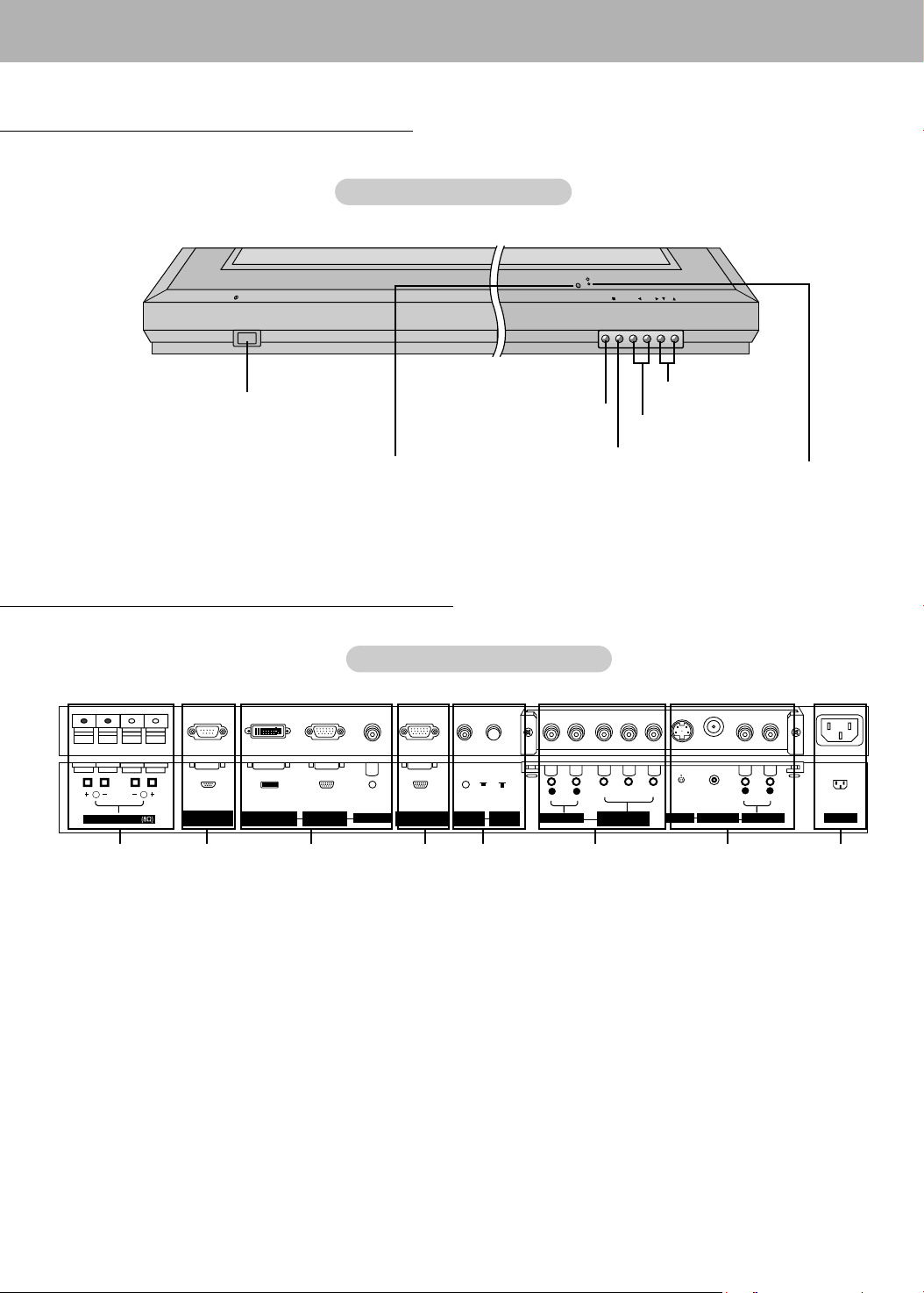
Front Panel Controls
Front Panel Controls
Main Power Button
Remote Control Sensor
Connection Options
Back Connections Panel
Back Connections Panel
12 3
1. EXTERNAL SPEAKER (8 ohm output)
Connect to optional external speaker(s).
*For further information, refer to ‘Speaker & Speaker Stand’
manual.
2. RS-232C INPUT (CONTROL/SERVICE) PORT
Connect to the RS-232C port on a PC.
3. AUDIO INPUT/RGB1 INPUT (PC/DTV INPUT)/
RGB2 INPUT (DIGITAL RGB INPUT) JACKS
Connect the monitor output connector of a PC to the appropriate input port.
4. RGB1 OUTPUT (PC/DTV OUTPUT) JACKS
Y ou can watch the RGB1 signal on another monitor, connect
RGB1 OUTPUT (PC/DTV OUTPUT) to another monitor’s
PC input port. Note: In standby mode, RGB1 output does not
work.
D,E Buttons
INPUT SELECT Button
VOLUME (F,G) Buttons
MENU Button
Power Standby Indicator
Illuminates red in standby mode,
Illuminates green when the
Monitor is turned on
4 5 8
6 7
5. CONTROL LOCK Switch
REMOTE CONTROL
When “CONTROLLOCK” is set to “ON”, the Monitor is operable by the external control device.
6. COMPONENT (DVD/DTV INPUT)/AUDIO INPUT JACKS
7. AUDIO/VIDEO INPUT JACKS
Connect audio/video out from external equipment to these
jacks.
S-VIDEO INPUTS (S-VIDEO)
Connect video out from an S-VIDEO VCR to the S-VIDEO
input.
8. POWER CORD SOCKET
This Monitor operates on an AC power. The voltage is indicated on the Specifications page. Never attempt to operate
the Monitor on DC power.
6
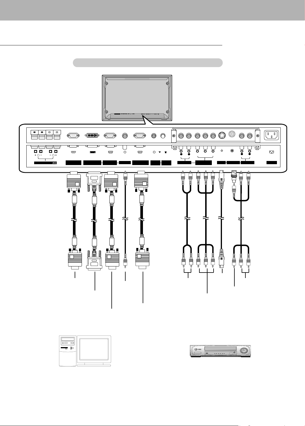
External Equipment Connections
R
( )
( )
( )
( )
L
REMOTE
CONTROL
RGB2 INPUT
(DIGITAL RGB INPUT)
RGB1 INPUT
(PC/DTV INPUT)
RGB1 OUTPUT
(PC/DTV OUTPUT)
COMPONENT
(DVD/DTV INPUT)
RS-232C INPUT
(CONTROL/SERVICE)
EXTERNAL SPEAKER
LOCK
CONTROL
ON/ OFF
YPBP
R
(MONO)
R
AUDIO
L
R
AUDIO
L
S-VIDEO VIDEO INPUT
AC INPUT
AUDIO INPUT
AUDIO INPUT
AUDIO INPUT
Monitor External Equipment Connection Panel
Monitor External Equipment Connection Panel
COMPONENT
AUDIO INPUT
COMPONENT
(DVD/DTV INPUT)
RS-232C INPUT
RGB2 INPUT
(DIGITAL RGB INPUT)
RGB1 INPUT
RGB
AUDIO
INPUT
RGB1 OUTPUT
(PC/DTV OUTPUT)
(PC/DTV INPUT)
Connection to PC
Connection to AV equipment
Note: The connection cables shown above to the right are not included with the Monitor.
A D-Sub 15-Pin Cable and a DVI Cable (shown above to the left) are provided to connect the Monitor to a PC.
S-VIDEO
INPUT
AUDIO INPUT
VIDEO INPUT
7

External Equipment Viewing Setups
atching VCR Setup
WWatching VCR Setup
- If you have a mono VCR, connect the audio output cable from the VCR to the Monitor's AUDIO (L/MONO) input.
- If you connect an S-VIDEO VCR to the S-VIDEO input, the picture quality is improved; compared to connecting a regular
VCR to the Video input.
- Avoid having a fixed image remain on the screen for a long period of time. Typically a frozen still picture from a VCR.
If a 4:3 picture format is used; the fixed image may remain visible on the screen.
- To avoid picture noise (interference), leave an adequate distance between the VCR and Monitor.
How to connect
- Connect the VCR's Video output jack (yellow) to the BNC-RCA adapter provided then to the VIDEO INPUT on the Monitor
and VCR audio outputs to Audio jacks of AUDIO INPUT.
- When connecting the Monitor to external equipment, match the colors of connecting jacks (Video = yellow, Audio (L) = white,
Audio (R) = red).
How to use
1. Use the INPUT SELECT button on the remote control to select VIDEO.
(If connected to S-VIDEO, select the
2. Insert a video tape into the VCR and press the PLAY button on the VCR. (See VCR owner’s manual)
S-VIDEO external input source.)
atching Cable
WWatching Cable
- After subscribing to a cable TV service from a local provider and installing a converter, you can watch cable TV programming. This monitor cannot display TV programming unless a TV tuner device or cable TV converter box is connected to the
Monitor.
- For further information regarding cable TV service, contact your local cable TV service provider(s).
How to connect
- Connect the cable box’s Video output jack (yellow) to the BNC-RCA adapter provided then to the VIDEO INPUT on the
Monitor and cable box’s audio outputs to Audio jacks of AUDIO INPUT.
How to use
1. Use the INPUT SELECT button on the remote control and select
2. Tune to cable service provided channels using the cable box.
atching External
WWatching External
How to connect
- Connect the external equipment’s Video output jack (yellow) to the BNC-RCA adapter provided then to the VIDEO
INPUT on the Monitor and external equipment’s audio outputs to Audio jacks of AUDIO INPUT
- When connecting the monitor to an external source, match the colors of AUDIO/VIDEO input jacks on the monitor with
the output jacks on the audio/video equipment: Video = yellow, Audio (Left) = white, Audio (Right) = red.
How to use
1. Use the INPUT SELECT button on the remote control to select
2. Operate the corresponding external equipment. See external equipment operating guide.
atching DVD Setup
WWatching DVD Setup
How to connect
- Connect DVD video outputs to Y, PB, PR of COMPONENT (DVD/DTV
INPUT) and audio outputs to AUDIO INPUT jacks.
- If your DVD only has an S-Video output jack, connect DVD S-Video
out to S-Video input on the monitor and DVD audio outputs to AUDIO
INPUT jacks.
How to use
1. Turn on the DVD player, and insert a DVD.
2. Use INPUT SELECT button on the remote control to select
NENT. Refer to the DVD player's manual for operating instructions.
TV Setup
TV Setup
A/V Source Setup
A/V Source Setup
VIDEO.
VIDEO.
COMPO-
• Component Input ports
To get better picture quality, connect a DVD
player to the component input ports as shown
below.
Component ports of the
Monitor
Video output ports
of DVD player
Y P
Y
Y
Y
Y
Pb
B-Y
Cb
P
B
B
8
P
Pr
R-Y
Cr
P
R
R

atching DTV Setup
WWatching DTV Setup
- To watch digitally broadcast programs, purchase/connect a digital set-top box.
- This monitor supports HDCP (High-bandwidth Digital Contents Protection) protocol for DVI DTV (480p,720p,1080i) mode.
How to connect a user-supplied Digital Set-Top Box
- Connect DTV set-top box video output to monitor COMPONENT (DVD/DTV INPUT) or to the monitor RGB1 (PC/DTV
INPUT), RGB2 (DIGITALRGB INPUT) connector depending on your set-top box connectors.
- Connect DTV set-top box audio outputs to monitor AUDIO INPUT jacks.
How to use
1. Turn on the a digital set-top box. (Refer to the owner’s manual for the digital set-top box)
2. Use INPUT SELECT on the remote control to select COMPONENT or RGB 1, RGB 2.
PC Setup
PC Setup
- To enjoy vivid picture and sound, connect a PC to the Monitor.
- Avoid keeping a fixed image on the monitor’s screen for a long period of time. The fixed image may become permanently imprinted on the screen; use a screen saver when possible.
- Connect PC to the RGB1 INPUT(PC/DTV INPUT) or RGB2 INPUT (DIGITAL RGB INPUT) port on the Monitor; change
the resolution output of PC accordingly.
- DDC protocol is preset for RGB1 (Analog RGB), and RGB2 (DVI, Digital RGB) modes.
- If required, adjust the monitor settings for Plug and Play functionally.
- If the graphic card on the PC does not output analog and digital RGB simultaneously, connect only one of both RGB1
INPUT (PC/DTV INPUT) or RGB2 INPUT (DIGITAL RGB INPUT) to display the PC on the monitor.
If the graphic card on the PC does output analog and digital RGB simultaneously, set the monitor to either RGB1 or
RGB2; (the other mode is set to Plug and Play automatically by the monitor.)
- DOS mode may not work depending on video card if using a DVI-I cable.
- To see a normal picture, match the VGAmode and DVI signal (640x480, 848x480, 852x480). (See page 20.)
- There may be noise associated with the resolution, vertical pattern, contrast or brightness in PC mode. If noise is present, change the PC mode to another resolution, change the refresh rate to another rate or adjust the brightness and
contrast on the menu until the picture is clear. If the refresh rate of the PC graphic card can not be changed, change the
PC graphic card or consult the manufacturer of the PC graphic card.
- The synchronization input form for Horizontal and Vertical frequencies is separate.
Setup Instructions to Connect a PC to your Monitor
- We recommend using 640x480, 60Hz for the PC mode, to get the best picture quality.
- If the resolution of PC is over UXGA, there will be no picture on the Monitor.
- Connect the signal cable from the PC's monitor output port to the Monitor's RGB1 INPUT (PC/DTV INPUT) port or the signal cable from the PC's DVI output port to the Monitor's RGB2 INPUT (DIGITAL RGB INPUT) port.
- Connect the audio cable from the PC to the AUDIO INPUT jacks on the Monitor. (Audio cables are not included with the
Monitor).
- If using a sound card, adjust PC sound as required.
- This monitor provides a VESA Plug and Play capability. The monitor sends EDID data to the PC system with a DDC protocol. The PC adjusts automatically to use this monitor.
- The monitor perceives 640x480, 60Hz as DTV 480p based on the PC graphic card. In this case, change the screen scanning rate for the graphic card.
How to use
1. Turn on the PC and the Monitor.
2. Turn on the display by pressing the POWER button on the Monitor ’s remote control.
3. Use the INPUT SELECT button on the remote control to select the RGB 1 or RGB 2 input source.
4. Set the resolution output of the PC to SXGA or under (1280 x 1024, 60Hz).
9
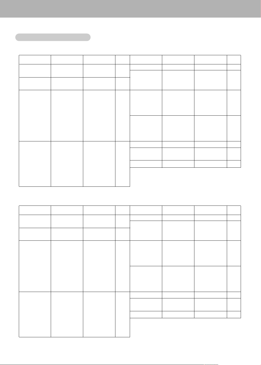
Monitor Display Specifications
Monitor Display Specifications
RGB1 Mode
Resolution
640x350
640x400
640x480
800x600
Horizontal
Frequency(KHz)
31.468
37.861
31.469
37.927
31.469
35.000
37.861
37.500
43.269
45.913
53.011
64.062
35.156
37.879
48.077
46.875
53.674
56.000
64.016
Vertical
Frequency(Hz)
70.09
85.08
70.08
85.03
59.94
66.66
72.80
75.00
85.00
90.03
100.04
120.00
56.25
60.31
72.18
75.00
85.06
90.00
100.00
Horizontal
Frequency(KHz)
49.725
31.469
35.000
37.500
48.363
56.476
60.023
68.677
54.348
63.995
67.500
77.487
68.681
60.000
75.000
63.981
o
o
o
o
o
o
o
o
o
o
Resolution
832x624
848x480
or
852x480
1024x768
1152x864
1152x870
1280x960
1280x1024
DDC DDC
Vertical
Frequency(Hz)
74.55
59.94
70.06
75.00
60.00
70.06
75.02
84.99
60.05
70.01
75.00
85.05
75.06
60.000
75.00
60.02
o
o
o
o
o
o
o
o
o
o
o
RGB2 Mode
Resolution
640x350
640x400
640x480
800x600
Horizontal
Frequency(KHz)
31.468
37.861
31.469
37.927
31.469
35.000
37.861
37.500
43.269
45.913
53.011
64.062
35.156
37.879
48.077
46.875
53.674
56.000
64.016
Vertical
Frequency(Hz)
70.09
85.08
70.08
85.03
59.94
66.66
72.80
75.00
85.00
90.03
100.04
120.00
56.25
60.31
72.18
75.00
85.06
90.00
100.00
DDC DDCResolution
832x624
848x480
o
o
o
o
or
852x480
1024x768
1152x864
1152x870
1280x960
1280x1024
Horizontal
Frequency(KHz)
49.725
31.469
35.000
37.500
48.363
56.476
60.023
68.677
54.348
63.995
67.500
77.487
68.681
60.000
75.000
63.981
Vertical
Frequency(Hz)
74.55
59.94
70.06
75.00
60.00
70.06
75.02
84.99
60.05
70.01
75.00
85.05
75.06
60.000
75.00
60.02
o
o
o
o
o
o
10
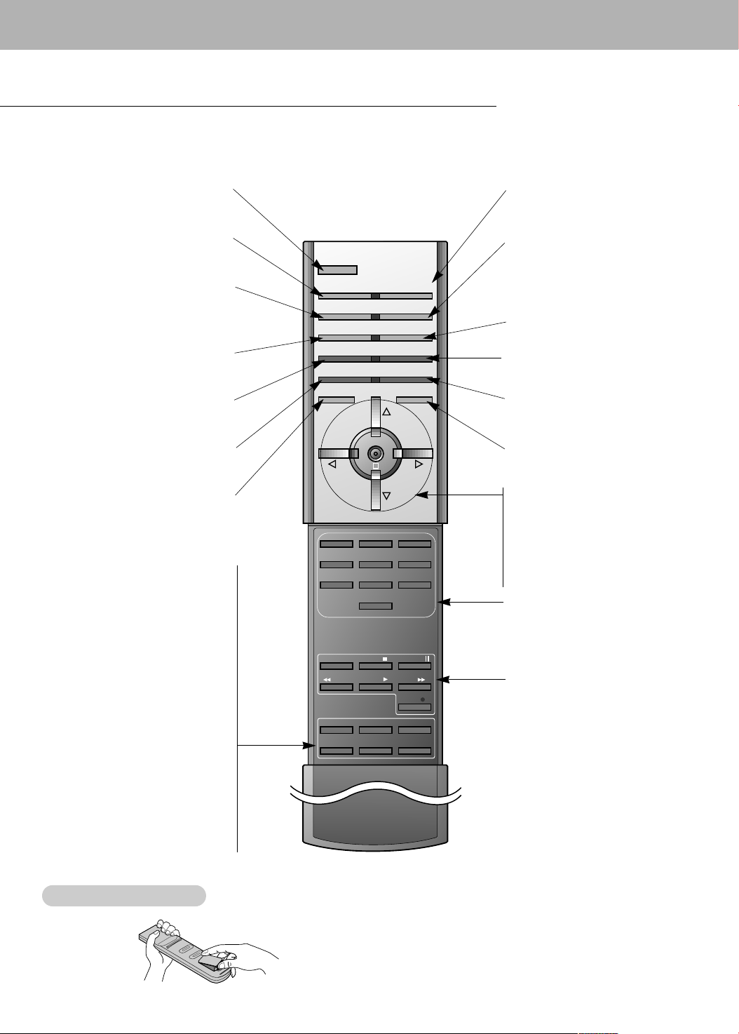
Remote Control Key Functions
123
456
7809
POWER
SLEEP INPUT SELECT
APC DASP
ARC
AUTO CONFIG.
ZOOM -
ZOOM +
SPLIT ZOOM
MENU MUTE
OK
VOL
POWER STOP
PLAY FF
REC
REW
P/STILL
PIP
TWIN PICTURE
PIP POSITION
PIP STILL
SOUND SELECT
PIP INPUT
VOL
KEY LOCK
- When using the remote control, aim it at the remote control sensor on the Monitor.
- Under certain conditions or if the IR code from remote is interrupted, function may not occur. Repeat key presses if
necessary.
Switches the Monitor on from
standby or off to standby.
Sets the sleep timer.
(Refer to p.17)
Adjusts the factory preset
picture according to the room.
(Refer to p.15)
Changes the picture format.
(Refer to p.21)
Reduces the main picture size.
Enlarges a screen section.
Displays on screen menus.
Memorizes menu changes.
(Refer to p. 21)
SPLIT ZOOM
(Refer to p. 21)
Exits the current menu.
Switches the sub picture
on and off. (Refer to p. 22)
TWIN PICTURE
(Refer to p. 23)
PIP INPUT
Selects the input source for the
sub picture. (Refer to p. 22, 23)
Selects main picture sound or sub
SOUND SELECT
picture sound for PIP.
(Refer to p. 22, 23)
PIP POSITION
Changes the sub picture position.
(Refer to p. 22)
Installing Batteries
Installing Batteries
Freezes sub picture motion.
(Refer to p. 22, 23)
PIP STILL
POWER
SLEEP
APC
ARC
ZOOM-
MENU
PIP
INPUT SELECT
Selects:
VIDEO, S-VIDEO, RGB1-2
or COMPONENT mode.
DASP
Selects the sound appropriate to
your viewing program character:
FLAT, SPORTS, CINEMA, MUSIC,
or USER (Refer to p.16)
AUTO CONFIG
(Refer to p.19)
ZOOM+
Enlarges the main picture size.
(Refer to p. 21)
KEY LOCK
To operate the monitor with remote
control only. (Refer to p. 18)
MUTE
Switches the sound on or off.
OK
D / E
Select menu options.
F / G (Volume button)
Increases/decreases sound level.
Adjusts menu settings.
NUMBER buttons
VCR BUTTONS
Control LG video cassette recorders.
• Open the battery compartment cover on the back side and
insert the batteries with correct polarity.
• Install two AAA 1.5V alkaline batteries. Don’t mix used batteries
with new batteries.
11
 Loading...