

LG MU-42PZ41 Service Manual
1. Application Object
These instructions are applied to all of the PDP monitor, RF02RA.
2. Notes
(1) Because this is not a hot chassis, it is not necessary to use
an isolation transformer. However, the use of isolation
transformer will help protect test instrument.
(2) Adjustment must be done in the correct order.
(3) The adjustment must be performed in the circumstance of
25±5°C of temperature and 65±10% of relative humidity if
there is no specific designation.
(4) The input voltage of the receiver must keep 110~240V,
50/60Hz in adjusting.
(5) The receiver must be operated for about 15 minutes prior
to the adjustment.
¤ After receiving 100% white pattern, the receiver must be
operate prior to adjustment.(Or white condition in HEATRUN mode)
¤ŁEnter into HEAT-RUN mode
- Select the HEAT-RUN OFF by pressing ADJ Key on
Remote Control for adjustment.
- Press the VOL + Key in HEAT-RUN OFF.
(OSD display HEAT-RUN WHITE and screen display
100% FULL WHITE PATTERN)
[ Set is activated HEAT-RUN without signal generator in
this mode.
[ Single color pattern of HEAT-RUN mode uses to check
PANEL.(RED/BLUE/GREEN)
[Caution] If you turn on a still screen more than 20 minutes, a
afterimage may be occur in the black level part of the
screen.
Each PCB Assy must be checked by the Check JIG Set before
whole assembly. (Be careful the POWER PCB Assy not to
damage to PDP Module)
3. POWER PCB Assy Voltage Adjustment
(Va, Vs, -Vy, Vsetup Voltage Adjustment)
3-1. Test Equipment
D.M.M 1EA
3-2. Connection Diagram for Measuring
Refer to Fig 1.
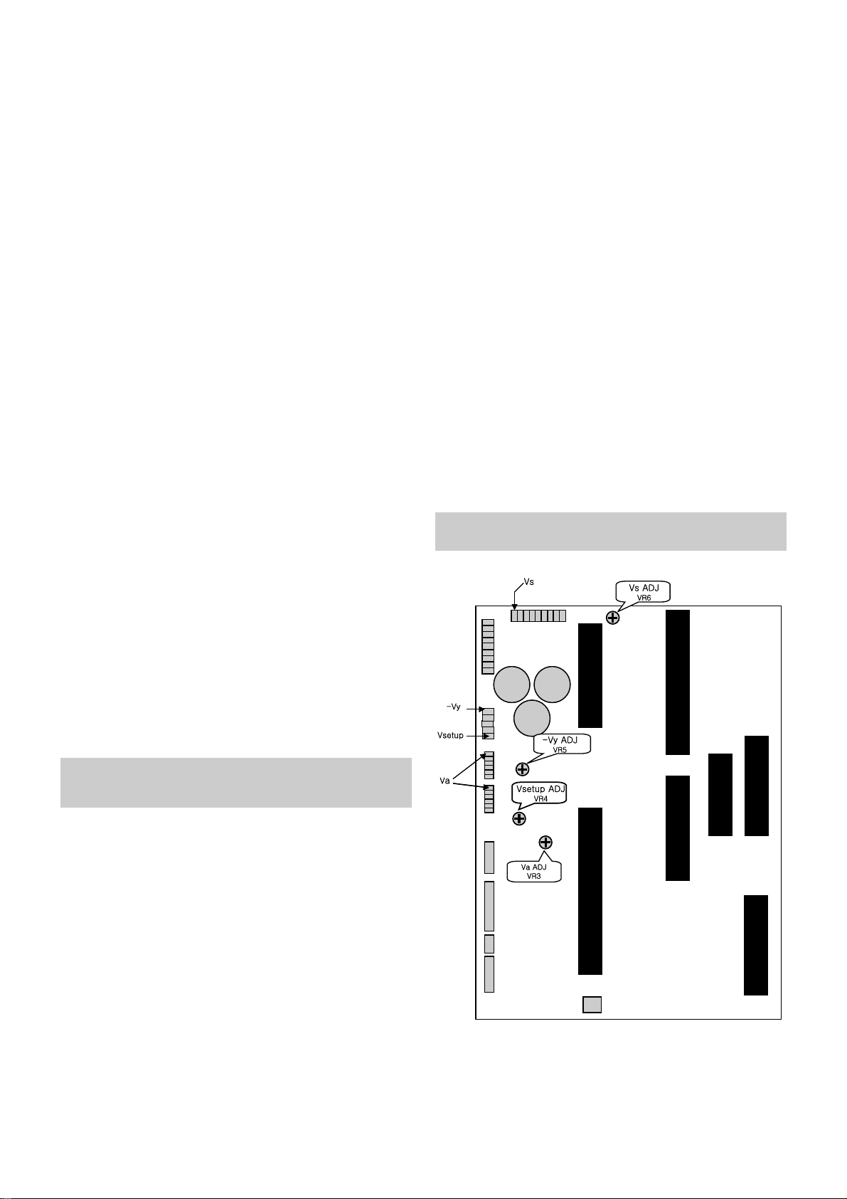
3-3. Adjustment Method(POWERWELL)
(1) Va Adjusment
¤ Connect pin 1 of CN205 to (+) jack of D.M.M.
¤ŁAfter turning the VR3(Va ADJ), voltage of D.M.M
adjustment as same as Va voltage which on label of
panel right/top.(Deviation : ±0.5V)
(2) Vs Adjustment
¤ Connect pin 1 of CN207 to (+) jack of D.M.M.
¤ŁAfter turning the VR6(Vs ADJ), voltage of D.M.M adjust
as same as Vs voltage which indicated on label of panel
right/top.(Deviation : ±0.5V)
(3) -Vy Adjustment
¤ Connect pin 1 of CN208 to (+) jack of D.M.M.
¤ŁAfter turning the VR5(-Vy ADJ), voltage of D.M.M adjust
as same as -Vy voltage which indicated on label of
panel right/top.(Deviation : ±0.5V)
(4) Vsetup Adjustment
¤ Connect pin 5 of CN208 to (+) jack of D.M.M.
¤ŁAfter turning the VR4(Vsetup ADJ), voltage of D.M.M
adjust as same as Vsetup voltage which indicated on
label of panel right/top.(Deviation : ±0.5V)
[ Refer to Typical Voltage
1. Va : 35 ~ 45V
2. Vs : 170 ~ 185V
3. -Vy : -60 ~ -90V
4. Vsetup : 210 ~ 240V
[ Replace PDP Module or Power Board, adjust certainly Power
PCB Assy Voltage.
- 6 -
ADJUSTMENT INSTRUCTIONS
<Fig 1> Connection Diagram of POWERWEL Power Adj. for
Measuring
- 7 -
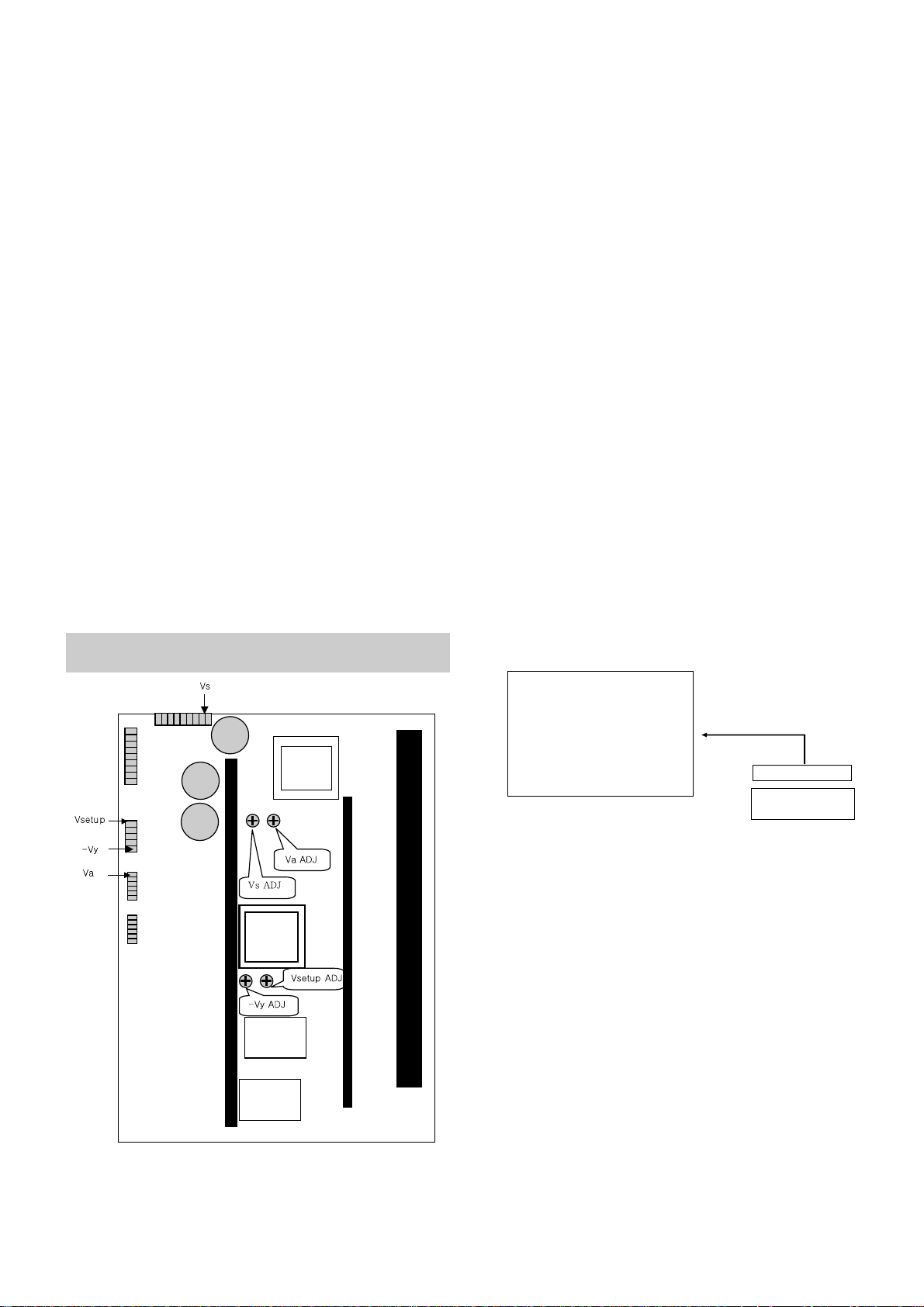
3-4. Adjustment Method(SONY)
(1) Va Adjusment
¤ Connect pin 1 of CN209 to (+) jack of D.M.M.
¤ŁAfter turning the VR402(Va ADJ), voltage of D.M.M
adjustment as same as Va voltage which on label of
panel right/top.(Deviation : ±0.5V)
(2) Vs Adjustment
¤ Connect pin 8 of CN207 to (+) jack of D.M.M.
¤ŁAfter turning the VR401(Vs ADJ), voltage of D.M.M
adjust as same as Vs voltage which indicated on label
of panel right/top.(Deviation : ±0.5V)
(3) -Vy Adjustment
¤ Connect pin 5 of CN208 to (+) jack of D.M.M.
¤ŁAfter turning the VR403(-Vy ADJ), voltage of D.M.M
adjust as same as -Vy voltage which indicated on label
of panel right/top.(Deviation : ±0.5V)
(4) Vsetup Adjustment
¤ Connect pin 1 of CN208 to (+) jack of D.M.M.
¤ŁAfter turning the VR404(Vsetup ADJ), voltage of D.M.M
adjust as same as Vsetup voltage which indicated on
label of panel right/top.(Deviation : ±0.5V)
[ Refer to Typical Voltage
1. Va : 30 ~ 50V
2. Vs : 170 ~ 185V
3. -Vy : -60 ~ -90V
4. Vsetup : 210 ~ 240V
[ Replace PDP Module or Power Board, adjust certainly Power
PCB Assy Voltage.
4. Adjustment of AUTO RGB
4-1. Outline
AUTO RGB adjustment is the function to set the optimum
black-level and Gain automatically in Analog --> Digital
converter and to correct RGB deviation.
4-2. Required Equipment
PC Pattern Generator
(It can be possible to output 16Gray Scale Pattern and RGB
output level is corrected to 0.7±0.1Vp-p)
4-3. Adjustment Method
(1) It can be possible to RGB input 16Gray Scale Pattern
signal of PC Mode and select RGB.
(2) Press the ADJ Key on R/C to enter adjustment mode and
select 2.W/B and then press the VOL + Key.
(3) Turn the HEATRUN OFF and select AUTO RGB and then
press the VOL + Key.
5. Adjustment of White Balance
5-1. Required Equipment
(1) Color analyzer(CA-100 or same production)
(2) Auto Regulator(Required while auto adjustment, and
possible to communicate with RS-232C)
(3) AV Pattern Generator
5-2. Connection Diagram of Equipment for
Measuring
[ After stop the Micom by pressing IN-START Key on Remote
Control, insert the P1002 with automatic adjustment of
connector.
After remove connector, move the Micom by pressing ENTER
Key.
<Fig 1> Connection Diagram of SONY Power Adj. for
Measuring
COLOR
ANALYZER
TYPE; CA-100
CVBS Signal Input
PDP MONITOR
85IRE Full White
85IRE
Full White
MSPG-2100 or
MSTG-5200
<Fig 2> Connection Diagram of Automatic Adjustment

- 8 -
5-3. Adjustment of White Balance
• Operate the Zero-calibration of the CA—100, then stick
sensor to PDP module surface when you adjust.
• For manual adjustment, it is also possible by the following
sequence.
(1) Select WHITE PATTERN of HEAT RUN mode by pressing
ADJ button on Remote Control for adjustment then operate
HEAT RUN more than 15 minute.
(2) Supply Full White signal(signal output level : 85IRE) in AV
Pattern Generator.
(3) Select image regulation status to ‘Clear Image’.
(4) Stick sensor to the center of screen and press the ADJ Key
on R/C to select W/B and then press the VOL + Key to
enter the adjustment mode.
After selecting R ADJ and B ADJ, press the VOL +/- Key
and adjust it until color coordination becomes(B GAIN
fixation)
color coordination : X=0.280±0.003, Y=0.290±0.003
color temperature : 10,000
cK ± 500cK
(5) Exit adjustment mode using Enter button.

- 9 -
BLOCK DIAGRAM
- 10 -
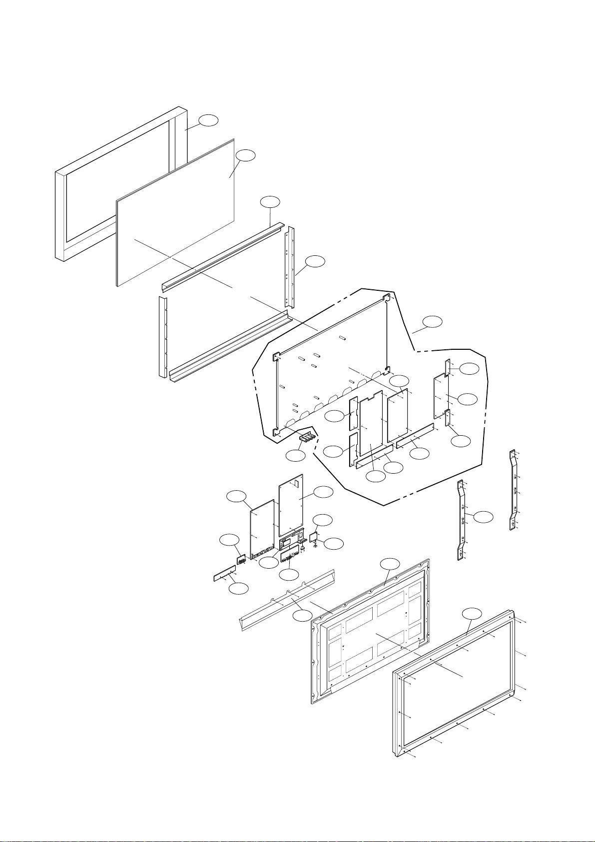
EXPLODED VIEW
200
203
201
202
205
204
207
208
209
206
540
401
550
310
551
520
560
570
400
410
530
580
210
301
302
300
305
- 11 -
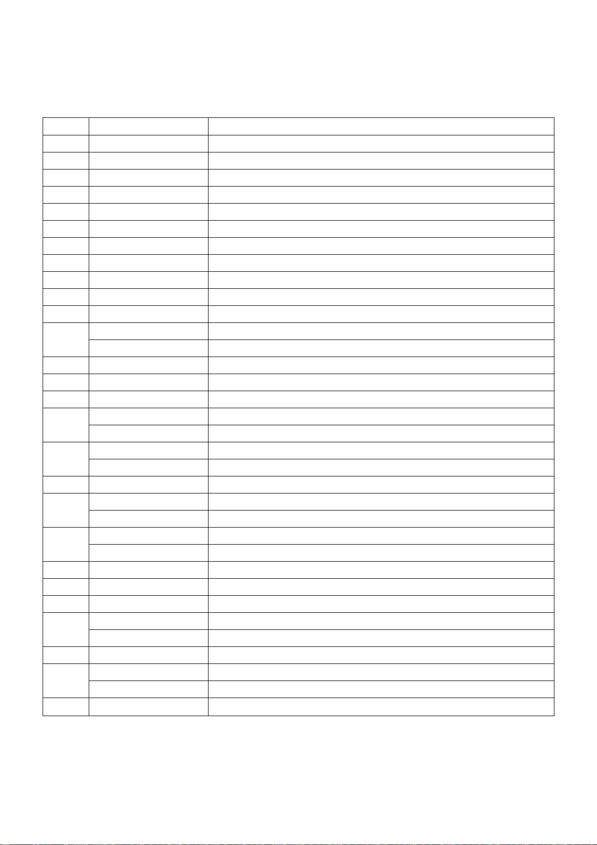
EXPLODED VIEW PARTS LIST
200 6348Q-E034A PDP,42 16:9 LOW VOTAGE DRIVING, FOR INTERCOMPANY DOMESTIC
201 6871QTH025A PCB ASSEMBLY,ZCNT ASSY HAND INSERT 42SD4 ZCNT TOP
202 6871QZH023A PCB ASSEMBLY,ZSUS ASSY HAND INSERT 42SD4
203 6871QTH026A PCB ASSEMBLY,ZCNT ASSY HAND INSERT 42SD4 ZCNT(BTM)
204 6871QRH021A PCB ASSEMBLY,XRRT ASSY HAND INSERT 42SD4
205 6871QLH021A PCB ASSEMBLY,XRLT ASSY HAND INSERT 42SD4
206 6871QYH022A PCB ASSEMBLY,YSUS ASSY HAND INSERT 42SD4
207 6871QDH061A PCB ASSEMBLY,YDRV ASSY HAND INSERT 42SD4 YDRV BTM
208 6871QDH060A PCB ASSEMBLY,YDRV ASSY HAND INSERT 42SD4 YDRV TOP
209 6871QCH024A PCB ASSEMBLY,CTRL ASSY HAND INSERT 42SD4 CTRL B/D (4011/4021)
210 4980V00460A SUPPORTER,VERTICAL MN-42PZ40
300 3091V00B01H CABINET ASSEMBLY,MU-42PZ41B NON - BLACK
3091V00B01C CABINET ASSEMBLY,MU-42PZ41
301 4980V00457A SUPPORTER,FILTER NON MN-42PZ40
302 4980V00458A SUPPORTER,FILTER NON MN-42PZ40
305 3790V00281D WINDOW,1142G02D MN42PZ10 ETCHING MESH NBK
310 5020V00667B BUTTON,CONTROL MU-42PZ41B ABS, AF-303 6KEY BLACK COLOR
5020V00667A BUTTON,CONTROL MU-42PZ40
400 3809V00A47D BACK COVER ASSEMBLY,MU-42PZ41V NON PIVOT INNER
3809V00A47C BACK COVER ASSEMBLY,MU-42PZ40
401 3301V00010C PLATE ASSEMBLY,A/V 3300V00205A MU/MP-42PZ41
410 3809V00A58C BACK COVER ASSEMBLY,MU-42PZ41B NON BLACK SPRAY
3809V00A58A BACK COVER ASSEMBLY,MU-42PZ40
520 6871VMMD05A PCB ASSEMBLY,MAIN RF-02RA PIVOT MU-42PZ41V
6871VMMC14A PCB ASSEMBLY,MAIN RF-02RA MU-42PZ40
530 6871VSMD84A PCB ASSEMBLY,SUB A/V RF02RA SAGE2
540 6871VSMD92A PCB ASSEMBLY,SUB CONT RF02RA MU-42PZ41
550 6871VSMD94A PCB ASSEMBLY,SUB PSW RF02RA MU-42PZ41
551 5020V00666B BUTTON,POWER MU-42PZ41B ABS, AF-303 1KEY BLACK COLOR
5020V00666A BUTTON,POWER MU-42PZ40
560 6871VSMD93A PCB ASSEMBLY,SUB SPK RF02RA MU-42PZ41
570 3501V00115A BOARD ASSEMBLY,POWER BOARD SONY 40/42 PDP ONE BOARD
3501V00116A BOARD ASSEMBLY,POWER BOARD SONY 40/42 PDP ONE BOARD
580 6871VSMD85A PCB ASSEMBLY,SUB INTER RF02RA SAGE2 FIX BD
No.
Part No.
Description
 Loading...