

Page 1
PLASMA MONITOR
ON/OFF
INPUT
SELECT
VOLUME
P/NO : 3828VA0373E
(NP00KB, 067M TX, 373-026H)
PLASMA MONITOR
Please read this owner’s manual carefully before
operating the Monitor.
Retain it for future reference.
Record model number and serial number of the
Monitor.
See the label attached on the back of the Monitor
and quote this information to your dealer when you
require service.
Model number :
Serial number :
MT-60PZ12V/A/B/K/S
MT-60PZ14V/A/B/K/S
MZ-60PZ14V/A/B/K/S
OWNER’S MANUAL
Page 2
The explanation about noise of 60" PDP
In the same way that a fan is used in a PC to keep the CPU cool, the PDP is equipped with cooling fans to
improve the reliability of this product. Therefore, a certain level of noise could occur when the fan is operated. This noise doesn't have any negative effect on its efficiency and liability and it's also determined to
have no difficulty while using this product. The noise from the fans is normal in the operation of this product. We hope you will understand that a certain level of noise is acceptable. It means that it is not changeable nor refundable.
The explanation about coloured dots may be present on PDP screen
The PDP which is the display device of this product is composed of 0.9 to 2.2 million cells and a few cell
defects can occur in the manufacture of the PDP. Several coloured dots visible on the screen would be
acceptable, in line with other PDP manufacturers and would not mean that the PDP is faulty. We hope you
will understand that the product which corresponds to this standard is regarded as acceptable. It means
that it could not be changed or refunded.
We promise that we'll do our best to develop our technology to minimize the cell defects.
What is a Plasma Display ?
If voltage is inputted to gas in glass panels, ultraviolet rays is outputted and fused with a fluorescent substance.
At this moment, light is emitted. APlasma Display is a next generation flat Display using this phenomenon.
160° - Wide angle range of vision
A Plasma Display provides more than 160° angle range of vision so that you can get a picture without distortion from any direction.
Easy installation
A Plasma Display is much lighter and smaller than other same class products so that you can install the
Plasma Display at the desired place.
Big screen
The screen of a Plasma Display is 60" so that you can get vivid experience as if you are in a theater.
Multimedia Plasma Display
A Plasma Display can be connected with a computer so that you can use it as a screen for conference,
game, internet and so on.
WARNING
This is Class B product. In a domestic environment this product may cause radio interference
in which case the user may be required to take adequate measures.
WARNING
TO REDUCE THE RISK OF FIRE AND ELECTRIC SHOCK, DO NOT EXPOSE THIS PRODUCT TO RAIN OR MOISTURE.
ON/OFF
INPUT
SELECT
VOLUME
Page 3

ENGLISH
After reading this
manual, keep it in
the place where
the user can
always contact
easily.
Contents
First step
Safety Instructions....................................................4
Monitor Overview
Controls of the Monitor.............................................8
Controls of the remote control................................12
Monitor Installation .................................................14
Equipment Connections and Setup
Watching VCR........................................................16
Watching Cable TV.................................................17
Watching external AV source..................................18
Watching DVD........................................................19
Connecting PC .......................................................20
Function checking in PC mode ..............................22
Adjusting in PC mode .............................................23
PIP function ............................................................26
Twin picture mode..................................................29
Using the remote control........................................31
Basic Features Setup and Operation
Turning on the Monitor...........................................32
Menu Rotation for Vertical Viewing ........................33
Function checking...................................................34
Sleep Timer
Setting Sleep Timer (Monitor turn-off time)............35
Picture & Sound
Auto picture control ................................................36
Adjusting picture condition .....................................37
DRP (Digital Reality Picture) ..................................38
Selecting menu options..........................................39
Adjusting Sound: Bass, Treble, Balance................40
Auto sound control .................................................41
AVL (Auto volume leveler)......................................42
Special Features
Using Still function..................................................43
Adjusting OSD Transparency.................................44
Adjusting colour temperature .................................45
Setting picture format.............................................46
External control device setup.................................47
IR Code (NEC Format) ...........................................56
Others
Troubleshooting check list......................................58
Product specifications.............................................59
Page 4
4
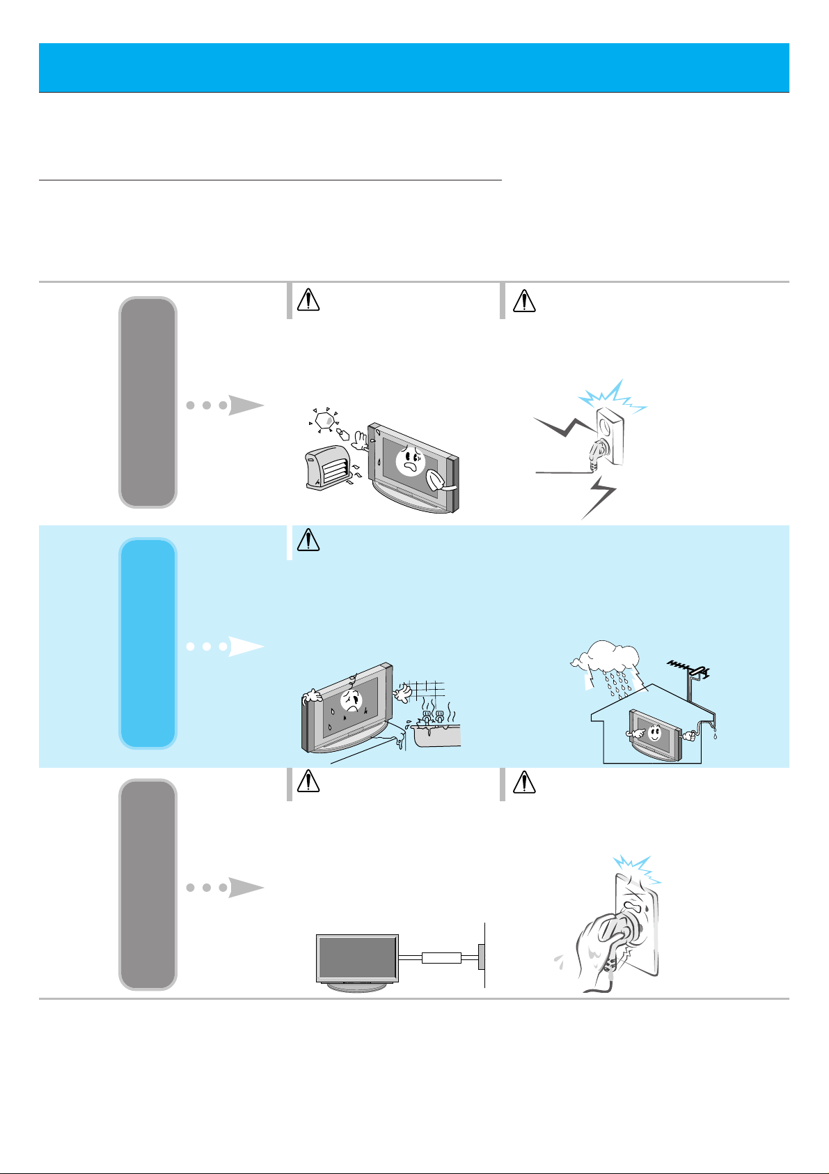
Safety Instructions
- It is recommended that this product only be used at an altitude of less than
6562 feet (2000m) to get the best quality picture and sound.
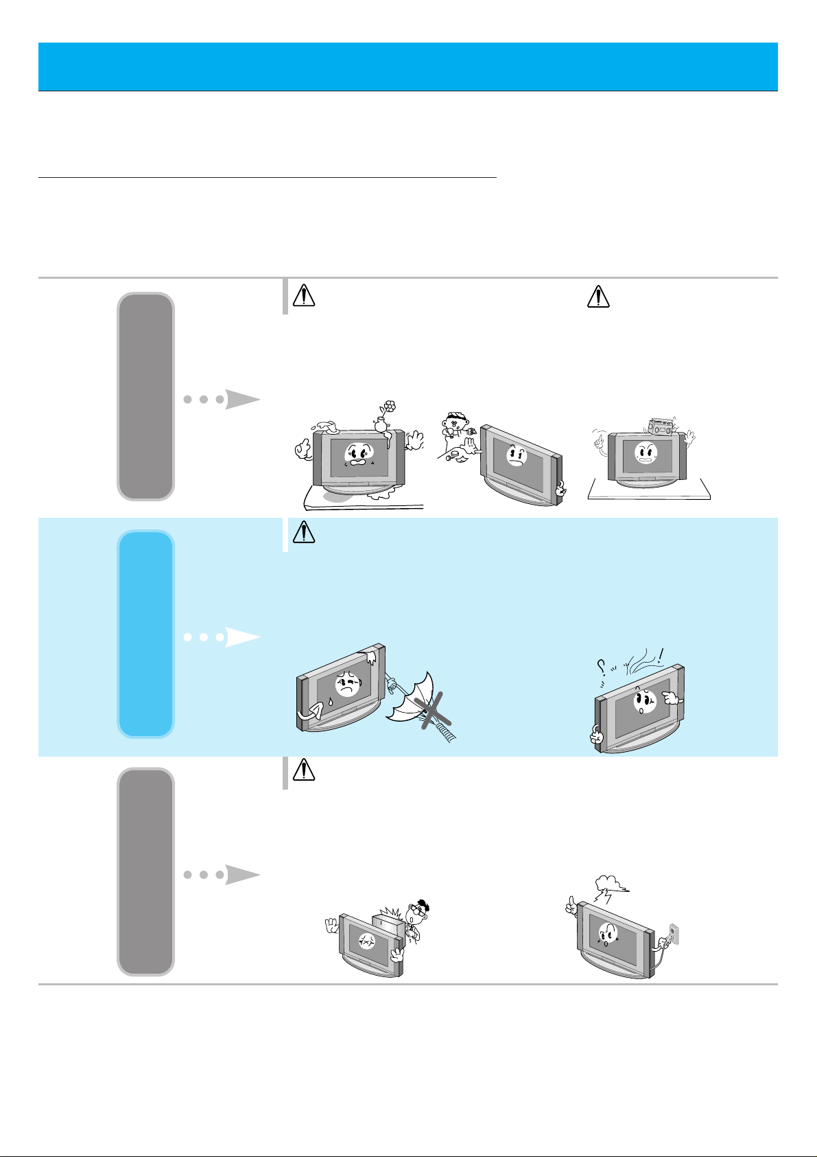
Do not place the Monitor in
direct sunlight or near heat
sources such as heat registers,
stove and so on.
- This may cause a fire.
WARNING
NOTES
Never touch the power plug
with a wet hand
- This may cause an electric shock.
WARNING
Do not use the Monitor in
damp place such as a bathroom or any place where it
is likely to get wet.
- This may cause a fire or could
give an electric shock.
Bend antenna cable between
inside and outside building to prevent rain from flowing in.
- This may cause water damaged inside
the Monitor and could give an electric
shock.
Indoor Installation Outdoor Installation Power
Earth wire should be connected.
- If the earth wire is not connected,
there is possible a danger of electric
shock caused by the current leakage.
- If grounding methods are not possible, a separate circuit breaker should
be employed and installed by a qualified electrician.
- Do not connect ground to telephone
wires, lightning rods or gas pipe.
Short-circuit
breaker
Disconnect from the mains
and remove all connections
before moving.
WARNING
NOTES
Page 5
5
ENGLISH
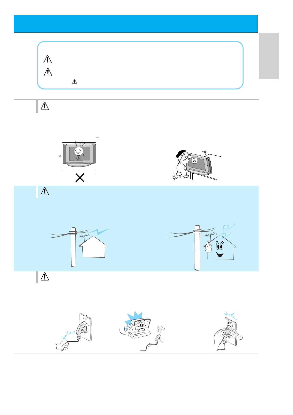
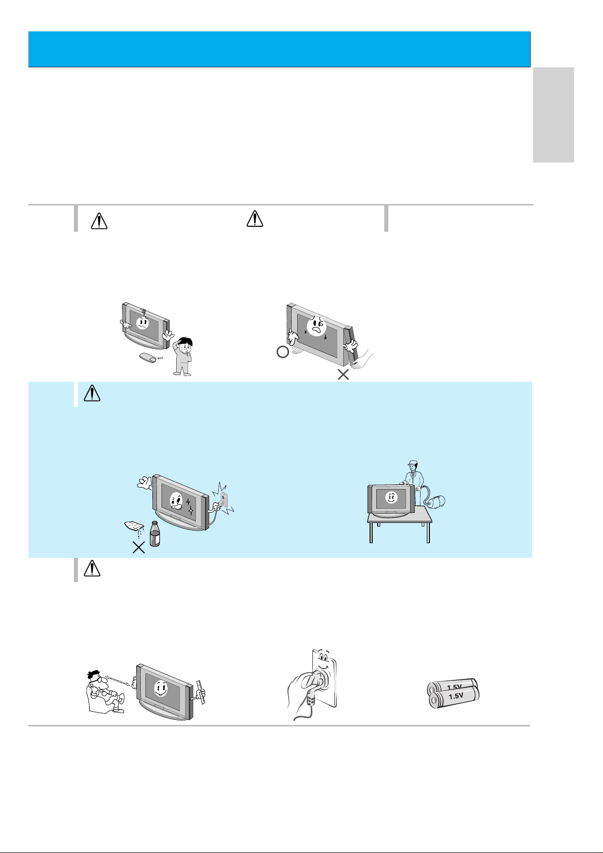
Do not place the Monitor in a built-in
installation such as a bookcase or
rack.
- Ventilation required.
NOTES
Do not pull the cord but the
plug when unplugging.
- This may cause a fire.
Ensure the power cord
doesn’t trail across any hot
objects like a heater.
- This may cause a fire or an elec tric shock.
Do not plug when the power
cord or the plug is damaged
or the connecting part of the
power outlet is loose.
- This may cause a fire or
an electric shock.
When installing the Monitor on a table,
be careful not to place the edge of its
stand.
- This may cause the Monitor to fall, causing
serious injury to a child or adult, and serious
damage to the Monitor.
NOTES
Do not place an outside antenna in
the vicinity of overhead power lines or
other electric light or power circuits.
- This may cause an electric shock.
There should be enough distance between an
outside antenna and power lines to keep the former from touching the latter even when the
antenna falls.
- This may cause
an electric shock.
*
Safety instructions have two kinds of information, and each meaning of it is as below.
Take care of danger that may happen under specific condition.
The violation of this instruction may cause serious injuries and even death.
The violation of this instruction may cause light injuries or damage of the
product.
WARNING
NOTES
NOTES
Page 6
6
Safety Instructions
Do not placing anything containing liquid
on top of the Monitor.
- This may cause a fire or
could give an electric
shock.
Do not insert any
object into the
exhaust vent.
- This may cause a fire or
could give an electric
shock.
NOTES
Do not place heavy
objects on the
Monitor.
- This may cause serious
injury to a child or adult.
WARNING
Do not attempt to service
the Monitor yourself.
Contact your dealer or service center.
- This may cause damaged the
Monitor or could give an electric
shock.
During a lightning thunder,
unplug the Monitor from the
wall outlet and don’t touch an
antenna cable.
- This may cause damaged the
Monitor or could give an
electric shock.
WARNING
Do not use water the Monitor
while cleaning.
- This may cause damaged the
Monitor or could give an electric
shock.
In case of smoke or strange
smell from the Monitor, switch it
off ,unplug it from the wall outlet
and contact your dealer or service center.
- This may cause a fire or could give
an electric shock.
Using Cleaning Others
WARNING
Page 7
7
ENGLISH
Dispose of used batteries
carefully to protect a child
from eating them.
- In case that it eats them, take it
to see a doctor immediately.
NOTES
When moving the Monitor
assembled with speakers do
not carry holding the speakers.
- This may cause the Monitor to
fall, causing serious injury to a
child or adult, and
serious
damage
to the
Monitor.
Avoid having a fixed image
remain on the screen for a
long period of time. Typically
a frozen still picture from a
VCR, 4:3 picture format or if
a CH label is present; the
fixed image may remain
visible on the screen.
NOTES
The distance between eyes
and the screen should be
about 5 ~ 7 times as long as
diagonal length of the
screen.
- If not, eyes will strain.
Unplug the Monitor from the
wall outlet when it is left
unattended and unused for
long periods of time.
- Accumulated dust may cause a
fire or an electric shock from
deterioration or
electric leakage.
Only use the specified batteries.
- This make cause damaged the
Monitor or could give an electric
shock.
NOTES
NOTES
Unplug this product from the wall outlet
before cleaning. Do not use liquid cleaners
or aerosol cleaners.
- This may cause damaged the Monitor or could give
an electric shock.
Contact the service center once a year to
clean the internal part of the Monitor.
- Accumulated dust can cause mechanical failure.
Page 8
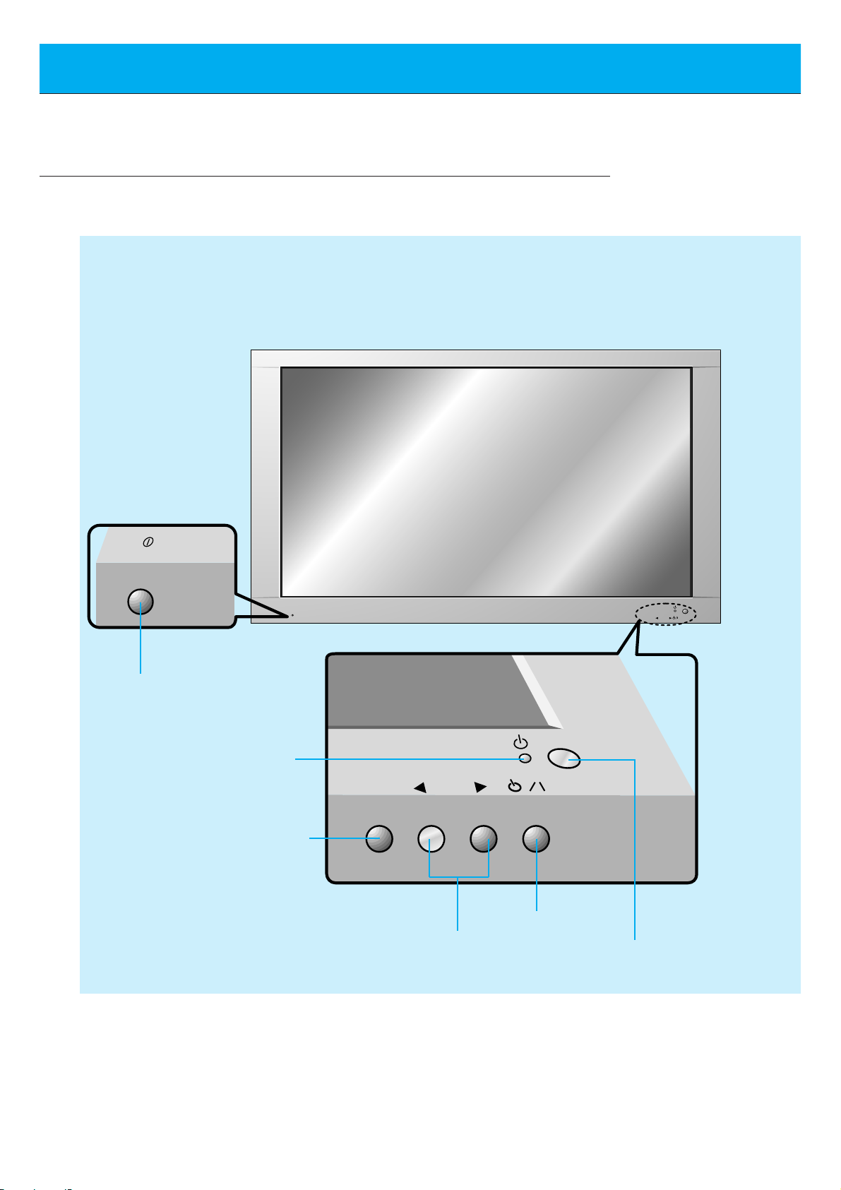
8
Controls of the Monitor
ON/OFF
ON/OFF
INPUT
SELECT
VOLUME
INPUT
SELECT
VOLUME
<Front Panel Controls>
Main power button
INPUT SELECT button
Sub power button
VOLUME (FF,GG) buttons
Power standby indicator
Illuminates red in standby mode
Illuminates green when the
Monitor is turned on
Remote control sensor
Page 9
9
ENGLISH
AUDIO
(MONO)
R L VIDEO Y P
B R
P
AV INPUT
AUDIO
R L
L
(+) ( ) (+)( )
R
EXTERNAL SPEAKER (8Ω) AC INPUTAUDIO INPUT
RS-232CS-VIDEO
COMPONENT(480i/480p)
RGB-PC INPUT
(VGA/SVGA/XGA/SXGA)
(DVD INPUT)
(+)
( )
(+)( )
EXTERNAL SPEAKER 8Ω
R L
AC INPUT
RGB-PC INPUT
R
AUDIO INPUT
L
AUDIO
(VGA/SVGA/XGA/SXGA)
RS-232C
AUDIO
(MONO)
R L
AV INPUT
S-VIDEO
COMPONENT(480i/480p)
(DVD INPUT)
VIDEO
Y P
BPR
REMOTE
CONTROL
CONTROL
LOCK
ON/ OFF
CONTROL
LOCK
REMOTE
CONTROL
ON/ OFF
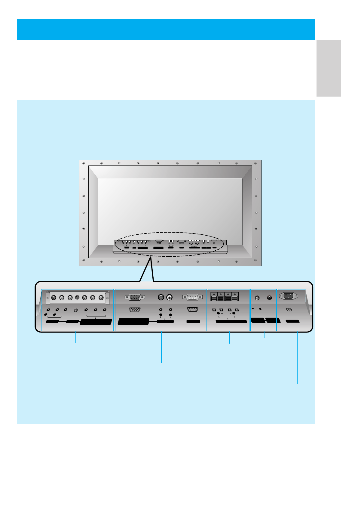
AV INPUT /
COMPONENT (480i/480p)
(DVD INPUT) SOCKETS
G The Interface board
(AP-60EA21) is not equipped on
MT/Z-60PZ14 series models. Contact
your dealer for buying this optional
item.
EXTERNAL SPEAKER
(8 ohm output)
RGB-PC INPUT
(VGA/SVGA/XGA/SXGA)/
AUDIO INPUT/
RS-232C jacks
POWER INPUT SOCKET
This Monitor operates on an AC mains sup-
ply, the voltage is as indicated as inside
back cover of this manual. Never apply DC
power to the Monitor.
CONTROL LOCK /
REMOTE CONTROL
When “CONTROL LOCK”
is set “ON”, wired remote
control mode is operated.
<Back Panel>
Page 10
10
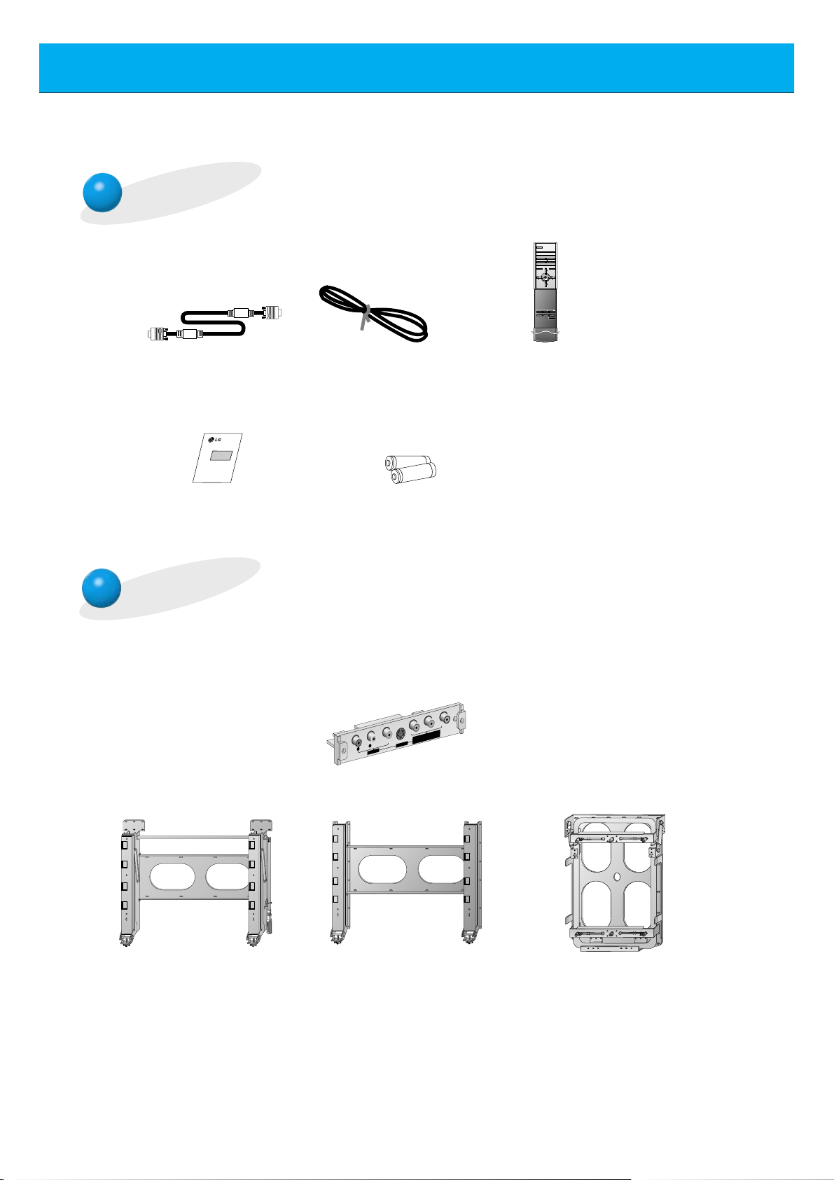
Accessories
D-sub 15 pin cable
Tilt wall mounting bracket
Wall mounting bracket Vertical Wall mounting bracket
AS mark
LG TV
Owner’s Manual
1.5V
1.5V
Alkaline batteries
(Optional)
interface board
Power cord
POWER
SLEEP INPUT SELECT
PSM SSM
ARC STILL
PIP
/ TWIN PICTURE
PIP INPUT
MENU MUTE
OK
VOL
POWER STOP
PLAY FF
REC
REW
P/STILL
VOL
POSITION
Remote control handset
Optional Extras
- Optional extras can be changed or modified for quality improvement without any notification new
optional extras can be added.
- Contract your dealer for buying these items.
P
B
Y
R
P
R L
AUDIO VIDEO
(MONO)
AV INPUT
S-VIDEO
(DVD INPUT)
COMPONENT (480i/480p)
Page 11
11
ENGLISH
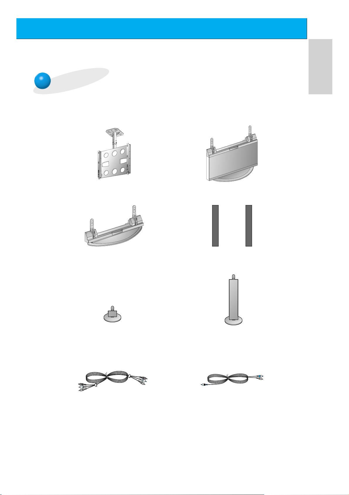
Optional Extras
Ceiling mounting bracket
Floor type stand
Desktop stand
Speakers
Speaker stand
Floor type speaker stand
Video cables
Audio cables
- Optional extras can be changed or modified for quality improvement without any notification new
optional extras can be added.
- Contract your dealer for buying these items.
Page 12
12
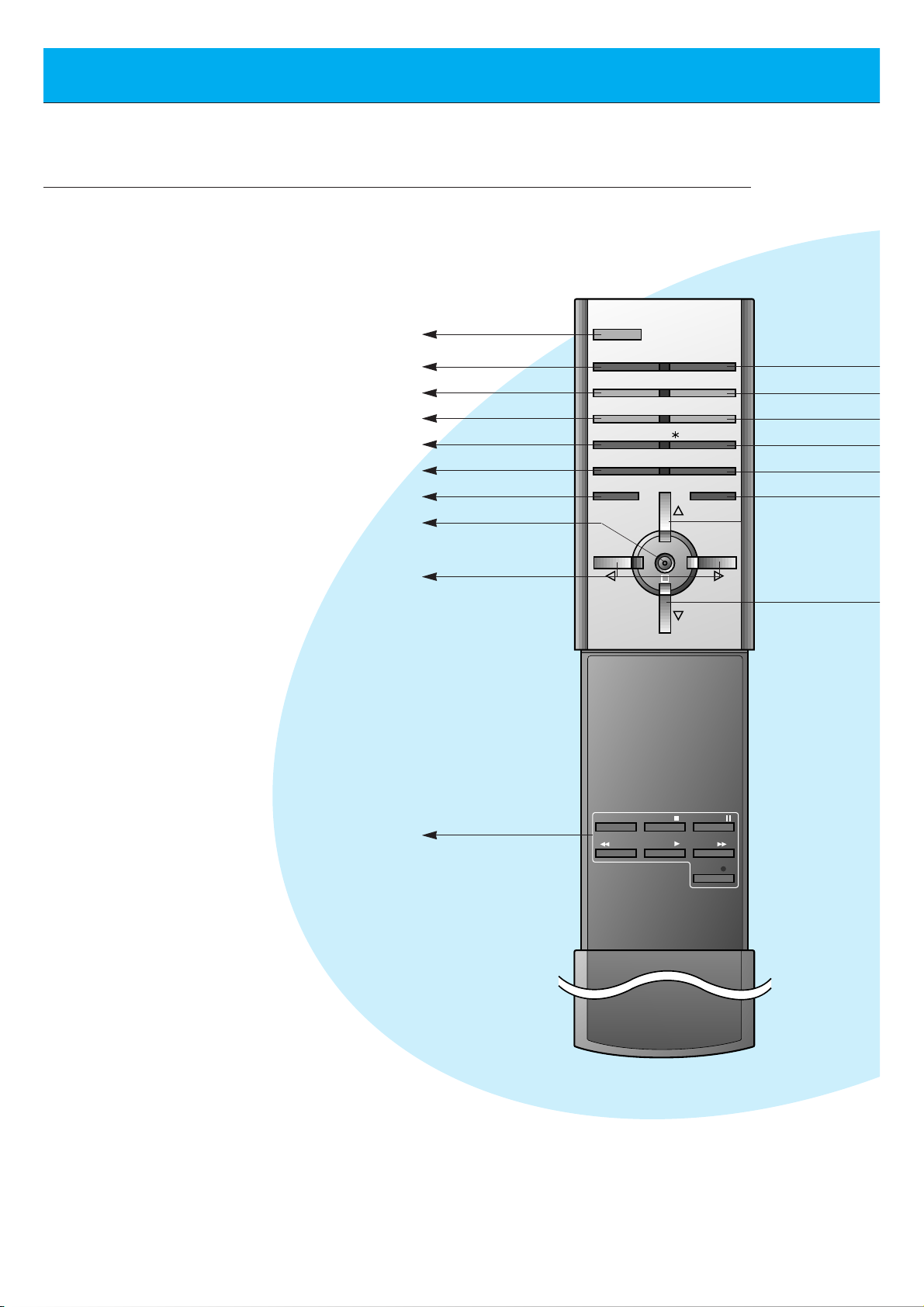
Controls of the remote control
- When using the remote control aim it at the remote control sensor of the Monitor.
POWER
SLEEP INPUT SELECT
PSM SSM
ARC STILL
PIP
/ TWIN PICTURE
PIP INPUT
MENU MUTE
OK
VOL
POWER STOP
PLAY FF
REC
REW
P/STILL
VOL
POSITION
POWER
SLEEP (Refer to p.35)
PSM (Refer to p.36)
ARC (Refer to p.46)
PIP (Refer to p.26)
PIP INPUT (Refer to p.27, 30)
MENU
OK
VCR BUTTONS
controls a LG video cassette
recorder.
VOLUME (FF, GG)
Page 13
13
ENGLISH
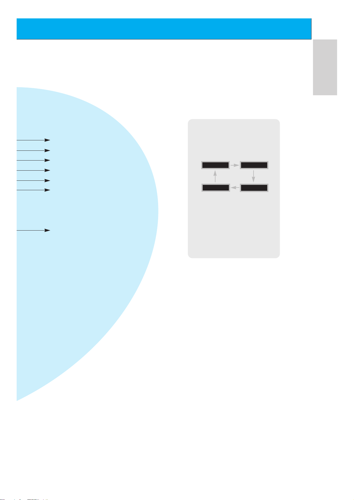
INPUT SELECT
SSM (Refer to p.41)
STILL (Refer to p.43)
POSITION (Refer to p.27)
DD/ EE
selects a menu item.
MUTE
switches the sound on or off.
TWIN PICTURE (Refer to p.29)
INPUT SELECT button on the
remote control
Each press of this button changes
the mode as shown below.
S-VIDEO
COMPONENT
VIDEO
RGB
G The Interface board
(AP-60EA21) is not equipped on
MT/Z-60PZ14 series models.
VIDEO, S-VIDEO, COMPONENT :
These modes are selected when the
Interface board (not supplied) is
installed.
Page 14
14
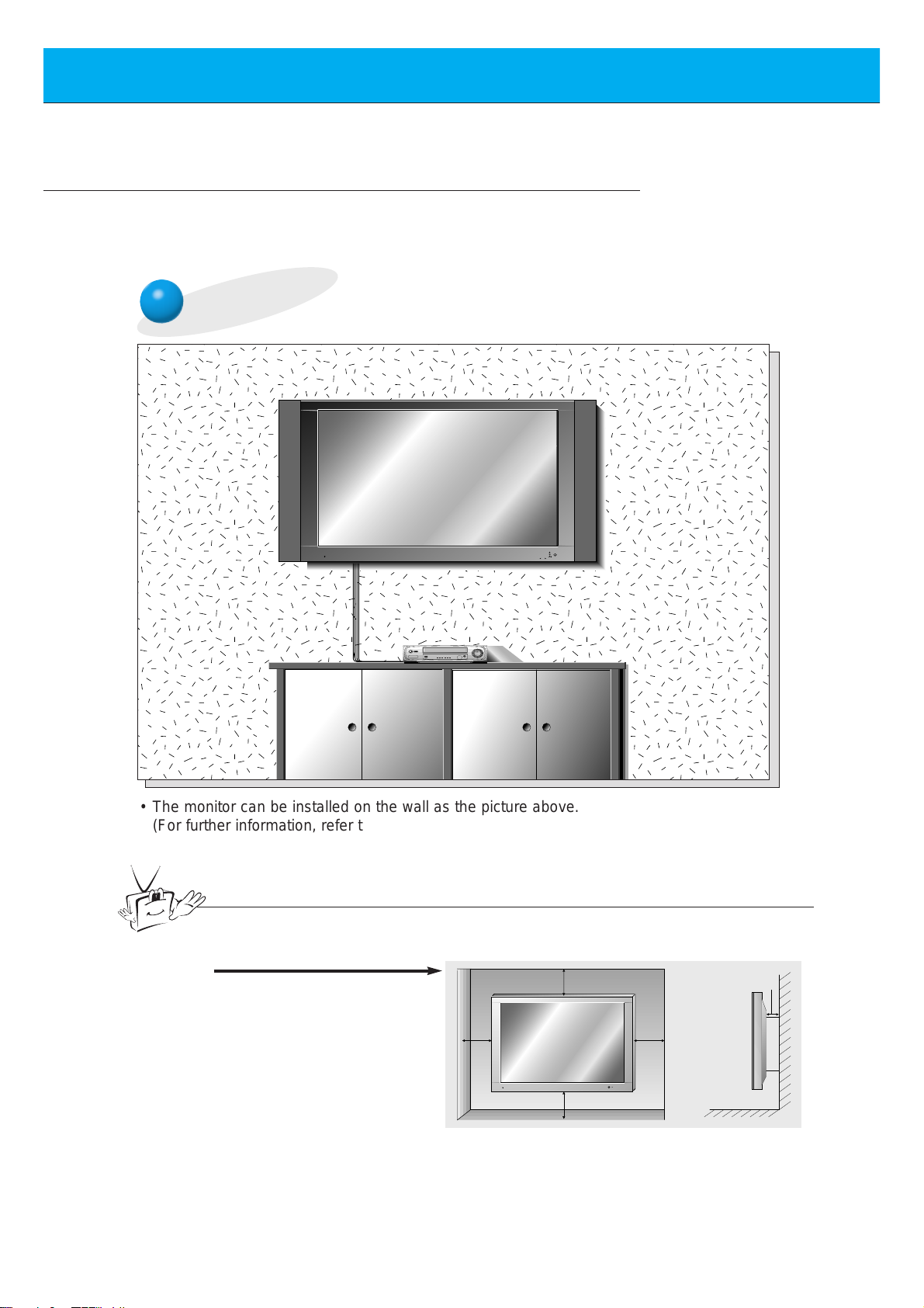
Monitor Installation
- This model can be installed on a wall as shown below. Wall mount is optional,
and is not supplied with the monitor.
- This plasma display is designed to be mounted horizontally or vertically.
Wall Mount: Horizontal Installation
• The monitor can be installed on the wall as the picture above.
(For further information, refer to ‘(Tilt) wall mounting bracket Installation and Setup
Guide’.)
Tips
• Install this monitor only in a location where adequate ventilation is available.
a.
(Wall mount minimum allowable
clearances for adequate
ventilation)
4 inches
4 inches
1.18 inch
4 inches4 inches
Page 15
15
ENGLISH
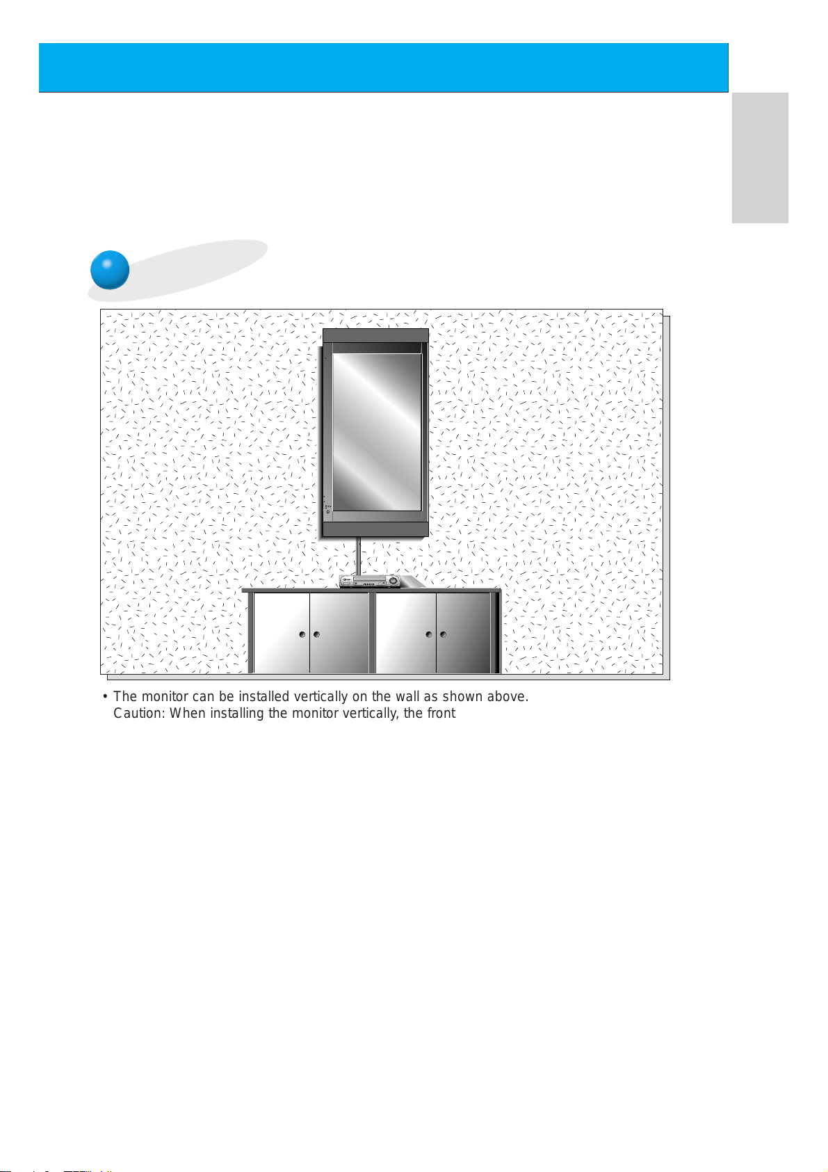
Wall Mount: Vertical Installation
,,,,,,,
,,,,,,,
,,,,,,,
,,,,,,,
• The monitor can be installed vertically on the wall as shown above.
Caution: When installing the monitor vertically, the front panel controls must be in the leftdown side position as shown above.
(For further information, refer to the optional ‘Wall Mounting Bracket Installation and Setup
Guide’.)
• Speakers are optional, and shown for illustration only.
• When installing the monitor vertically, you have to change the OSD display mode
so that the menus will appear correctly and also to protect the monitor from overheating (Refer to P. 33).
Caution
Caution
Page 16
16
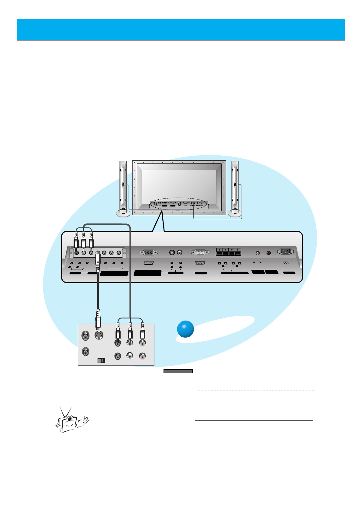
Watching VCR
(+) ( ) (+)( )
AUDIO
(MONO)
R L VIDEO Y P
B R
P
AV INPUT
AUDIO
R L
R
L
EXTERNAL SPEAKER (8Ω) AC INPUTAUDIO INPUT
RS-232CS-VIDEO
COMPONENT(480i/480p)
RGB-PC INPUT
(VGA/SVGA/XGA/SXGA)
(DVD INPUT)
CONTROL
LOCK
REMOTE
CONTROL
ON/ OFF
(+)
( )
(+)( )
EXTERNAL SPEAKER 8Ω
R L
AC INPUT
RGB-PC INPUT
R
AUDIO INPUT
L
AUDIO
(VGA/SVGA/XGA/SXGA)
RS-232C
AUDIO
(MONO)
R L
AV INPUT
S-VIDEO
COMPONENT(480i/480p)
(DVD INPUT)
VIDEO
Y P
BPR
REMOTE
CONTROL
CONTROL
LOCK
ON/ OFF
S-VIDEO
OUT
IN
(R) AUDIO (L) VIDEO
- When connecting the Plasma Monitor with external equipments, match the colours of connecting ports
(Video - yellow, Audio(L) - white, Audio(R) -red).
- If you have a mono VCR, connect the audio cable from the VCR to the AUDIO(L/MONO) input of the
Plasma Monitor.
- If you connect an S-VIDEO VCR to the S-VIDEO input, the picture quality is improved; compared to
connecting a regular VCR to the Video input.
- If 4:3 picture format or still word such as watching VCR or CH label is on the screen for a long time,
that fixed image may remain visible.
- Avoid having a fixed image remain on the screen for a long period of time. Typically a frozen still picture from a VCR, 4:3 picture format or if a CH label is present;
the fixed image may remain visible on the screen.
<Back panel of VCR>
To watch VCR
Press INPUT SELECT button on the
remote control and select VIDEO.
(When connecting with S-Video,
select the S-VIDEO.)
1
Insert a video tape into the VCR and
press the PLAY button on the VCR.
See VCR owner’s manual.
2
INPUT SELECT
<Back panel of the Monitor>
Tips
• To avoid picture noise (interference), leave an adequate distance between the VCR
and monitor.
(When the Interface board is installed.)
G The Interface board (AP-60EA21) is not equipped on
MT/Z-60PZ14 series models.
Page 17
17
ENGLISH
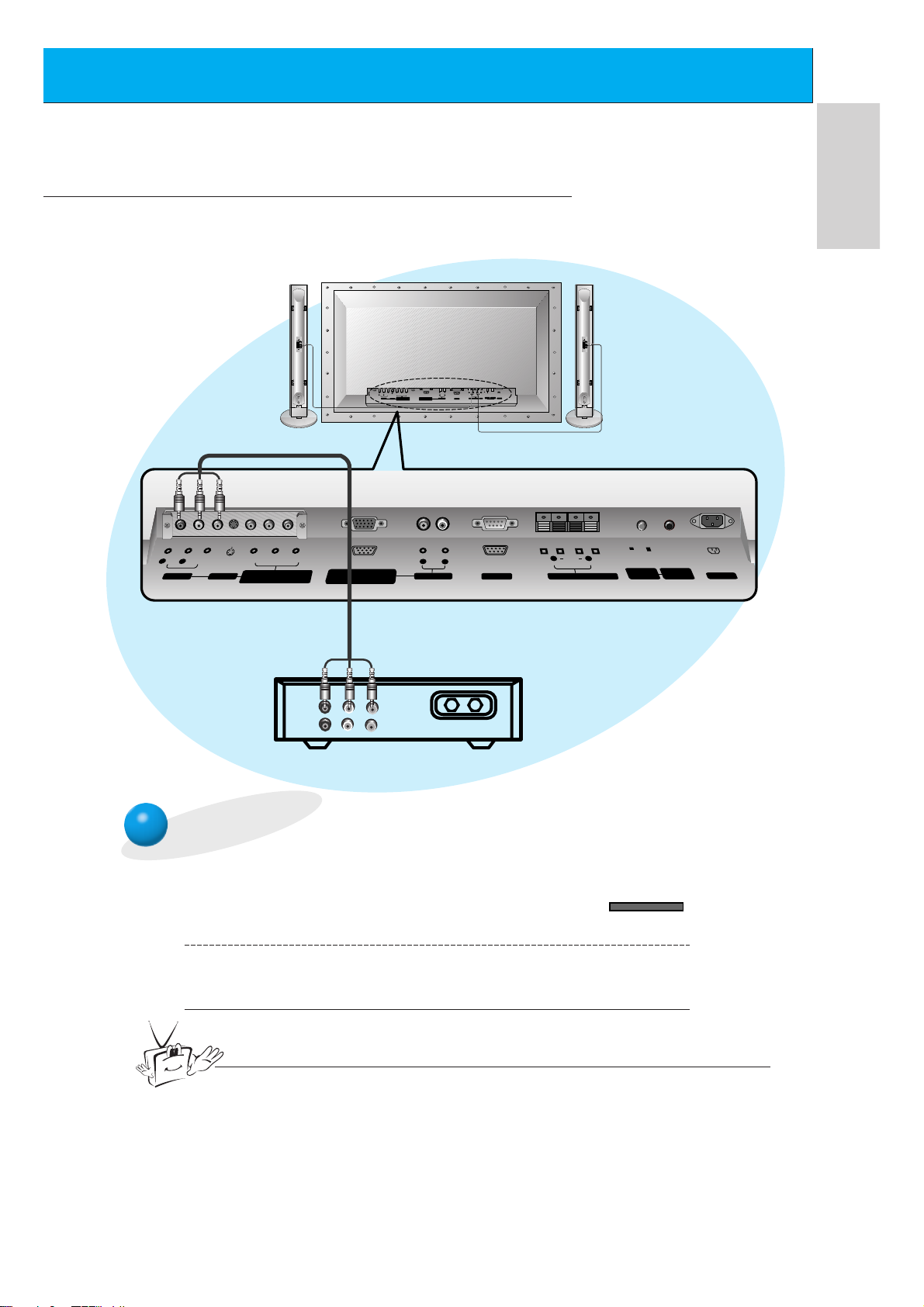
Watching Cable TV
- After subscribing to a cable TV service from a local provider and installing a converter,
you can watch cable TV programming.
To watch cable TV
Press INPUT SELECT button on the
remote control and select VIDEO.
1
Tune to cable service provided channels using
the cable box.
2
INPUT SELECT
Tips
• For further information regarding cable TV service, contact your local
cable TV service provider(s).
<Cable box>
<Back panel of the Monitor>
(When the Interface board is installed.)
G The Interface board (AP-60EA21) is not equipped on MT/Z-60PZ14 series models.
ON/ OFF
R
L
(MONO)
AUDIO
R L VIDEO Y P
AV INPUT
P
B R
COMPONENT(480i/480p)
RGB-PC INPUT
(VGA/SVGA/XGA/SXGA)
(DVD INPUT)
(+) ( ) (+)( )
R L
AUDIO
CONTROL
REMOTE
LOCK
CONTROL
EXTERNAL SPEAKER (8Ω) AC INPUTAUDIO INPUTS-VIDEO
RS-232C
R L
(+)
R L
AUDIO
AV INPUT
(MONO)
VIDEO
S-VIDEO
Y P
BPR
COMPONENT(480i/480p)
(DVD INPUT)
RGB-PC INPUT
(VGA/SVGA/XGA/SXGA)
AUDIO
R
AUDIO INPUT
L
RS-232C
( )
EXTERNAL SPEAKER 8Ω
(R) AUDIO (L) VIDEO
TV
VCR
RF Cable
ON/ OFF
(+)( )
CONTROL
LOCK
REMOTE
CONTROL
AC INPUT
Page 18
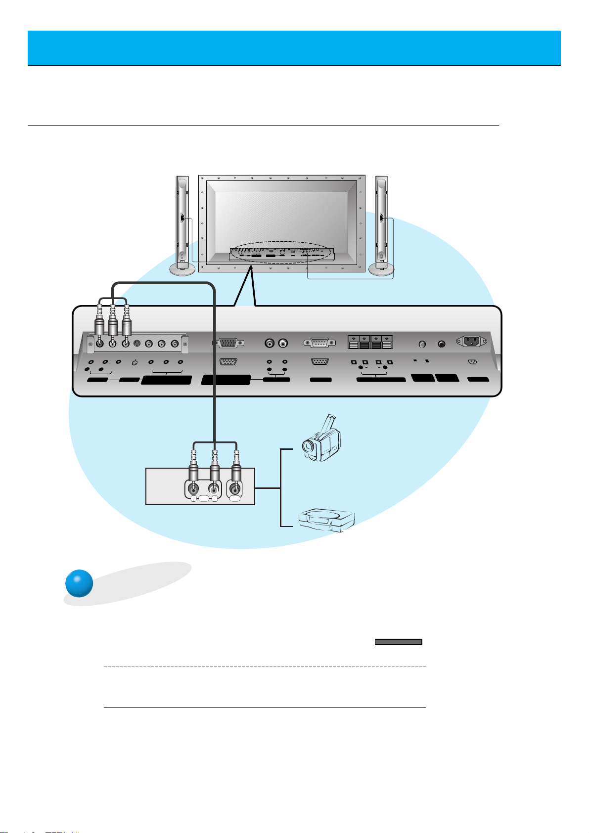
18
To watch external AV source
Press INPUT SELECT button on the
remote control of the monitor to select
VIDEO.
1
Operate the corresponding external equipment.
2
INPUT SELECT
Watching external AV source
- When connecting the Plasma Monitor with external equipments,
match the colours of connecting ports.
<Back panel of the Monitor>
(When the Interface board is installed.)
G The Interface board (AP-60EA21) is not equipped on MT/Z-60PZ14 series models.
ON/ OFF
R
L
(MONO)
AUDIO
R L VIDEO Y P
AV INPUT
COMPONENT(480i/480p)
P
B R
RGB-PC INPUT
(VGA/SVGA/XGA/SXGA)
(DVD INPUT)
(+) ( ) (+)( )
R L
AUDIO
CONTROL
REMOTE
EXTERNAL SPEAKER (8Ω) AC INPUTAUDIO INPUTS-VIDEO
LOCK
CONTROL
RS-232C
Y P
R L
AUDIO
AV INPUT
(MONO)
VIDEO
S-VIDEO
BPR
COMPONENT(480i/480p)
(DVD INPUT)
RGB-PC INPUT
(VGA/SVGA/XGA/SXGA)
AUDIO
R
AUDIO INPUT
L
AUDIO VIDEO
R L
ON/ OFF
(+)( )
CONTROL
LOCK
REMOTE
CONTROL
RS-232C
R L
(+)
( )
EXTERNAL SPEAKER 8Ω
Camcorder
Video game set
AC INPUT
Page 19

19
ENGLISH
Watching DVD
• Connect DVD video inputs to Y, PB, PR of COMPONENT (480i/480p) (DVD INPUT) and
audio inputs to Audio sockets of AV INPUT.
How to connect
How to use
• Press INPUT SELECT button on the remote control of the
monitor to select COMPONENT.
• Try this after turning on the DVD player.
• Component Input ports
You can get better picture quality if you
connect DVD player with component input
ports as below.
< Back panel of a DVD player>
Component ports of the
Monitor
Y
PB
PR
Video output ports
of DVD player
Y
Y
Y
Y
Pb
B-Y
Cb
PB
Pr
R-Y
Cr
P
R
< Back panel of the Monitor>
(When the Interface board is installed.)
G The Interface board (AP-60EA21) is not equipped on
MT/Z-60PZ14 series models.
(When the Interface board is installed.)
G The Interface board (AP-60EA21) is not equipped on MT/Z-60PZ14 series models.
ON/ OFF
R
L
R L
AUDIO
AV INPUT
(MONO)
VIDEO
S-VIDEO
Y P
BPR
COMPONENT(480i/480p)
(DVD INPUT)
R L VIDEO Y P
RGB-PC INPUT
(VGA/SVGA/XGA/SXGA)
(MONO)
AUDIO
P
B R
COMPONENT(480i/480p)
RGB-PC INPUT
AV INPUT
(DVD INPUT)
(VGA/SVGA/XGA/SXGA)
R
AUDIO INPUT
AUDIO
(+) ( ) (+)( )
R L
AUDIO
CONTROL
REMOTE
RS-232C
EXTERNAL SPEAKER (8Ω) AC INPUTAUDIO INPUTS-VIDEO
LOCK
CONTROL
R L
(+)
( )
L
RS-232C
EXTERNAL SPEAKER 8Ω
(+)( )
ON/ OFF
CONTROL
LOCK
REMOTE
CONTROL
AC INPUT
(R) AUDIO (L)
B
R
Page 20

INPUT SELECT
On the remote control
How to use
Back panel of the Monitor
20
- You can easily connect the Plasma Display to your PC for outstanding image and sound.
- Use the Monitor to display images and sound from a PC Computer source.
PC Setup
• First, turn on the PC computer and press the ON/OFF button on the
Monitor to apply power to it. Second, turn on the display by pressing
the button on the Monitor or by pressing the POWER button on
the Monitor’s remote control.
• Use the INPUT SELECT button on the remote control to select the
RGB input source.
• Set the resolution output of the PC to SXGAor under (1280 x 1024,
75Hz). (Refer to page 21.)
• Avoid keeping a fixed image on the Monitor's screen for a long period of time. The fixed image may
become permanently imprinted on the screen; use a screen saver when possible.
• If the resolution output of the PC computer is over SVGA, connect the PC to the RGB-PC
(VGA/SVGA/XGA/SXGA) input port on the Monitor. Change the PC computer resolution output
accordingly.
Setup Instructions to Connect a PC to your Monitor
Connecting a PC Computer Control Source
• If the image output of the PC is set higher than
UXGA, no picture will appear on the Monitor.
(UXGA is not supported.)
• Connect the signal cable from the monitor Output
port on the PC to the RGB-PC INPUT
(VGA/SVGA/XGA/SXGA) port on the Monitor.
• Connect the audio cable from the PC to the Audio
ports of the Monitor. (Audio cables are not supplied
with the Monitor.)
• To set up the Monitor to operate within a PC windows environment, select Normal, Standard or
Default monitor.
• The Monitor can not be used for Plug and Play
functionality.
• If your PC computer is equipped with a sound card,
adjust the sound output on the PC.
• It is recommended that the resolution output of the
PC should be set to 1280 x 720 to get the best
quality picture. (Look for a video card that uses the
nVIDIA GeForce 2 pro or similar chipset that
supports this resolution)
(MONO)
AUDIO
R L VIDEO Y P
P
B R
COMPONENT(480i/480p)
AV INPUT
(DVD INPUT)
Y P
R L
AUDIO
AV INPUT
(MONO)
VIDEO
S-VIDEO
BPR
COMPONENT(480i/480p)
(DVD INPUT)
RGB-PC INPUT
(VGA/SVGA/XGA/SXGA)
ON/ OFF
R
L
(+) ( ) (+)( )
R L
AUDIO
CONTROL
RGB-PC INPUT
(VGA/SVGA/XGA/SXGA)
AUDIO
R
AUDIO INPUT
REMOTE
EXTERNAL SPEAKER (8Ω) AC INPUTAUDIO INPUTS-VIDEO
RS-232C
LOCK
CONTROL
L
L
RS-232C
R L
(+)
( )
EXTERNAL SPEAKER 8Ω
ON/ OFF
(+)( )
CONTROL
LOCK
REMOTE
CONTROL
AC INPUT
Tips
Page 21

21
ENGLISH
Monitor Image Display Specifications
640x350
720x400
31.468 70.09
37.861 85.08
31.469 70.08
37.927 85.03
31.469 59.94
35.000
66.66
37.861 72.80
37.500 75.00
43.269 85.00
45.913 90.03
53.011 100.04
64.062 120.00
35.156 56.25
37.879 60.31
48.077
72.18
46.875
832x624
1024x768
1280x720
1152x864
1152x870
1280x960
1280x1024
75.00
53.674 85.06
56.000 90.00
64.016 100.00
49.725 74.55
48.363 60.00
56.476 70.06
60.023 75.02
68.677 84.99
54.348 60.05
52.400 69.98
63.995 70.01
67.500 75.00
77.487 85.05
68.681 75.06
60.000 60.00
75.000 75.00
63.981 60.02
79.976 75.02
Resolution
Horizontal
Frequency (KHz)
Vertical
Frequency (Hz)
640x480
800x600
Tips
• Synchronization input form : separate
Page 22

22
3
2
Function checking in PC mode
- Select RGB input source.
- PIP/DW function is worked when the interface board is installed.
Interface board (AP-60EA21) is not equipped on MT/Z-60PZ14 series models.
1
Press the MENU button.
Press the
G button and then press the D / E or
F / G button to select a function you want to use.
• Press the OK button to exit.
• The PIP works in VGA, SVGA, XGA, 60Hz.
• The TWIN PICTURE works in VGA, 60Hz.
Press the D / E button.
• Each time you press this button you can see menus as below.
MENU
VOL VOL
PSM G
DRP G
CONTRAST 85 G
BRIGHTNESS 50 G
COLOUR 50 G
TINT 0 G
SHARPNESS 50 G
MOVE GNEXT AEXIT
D
E
SSM G
AVL G
TREBLE 50 G
BASS 50 G
BALANCE 0 G
MOVE GNEXT AEXIT
D
E
OSD ROTATE G
ARC G
SCREEN G
TRANSPARENCY G
PIP/DW G
SET ID G
COLOUR TEMP. G
MOVE GNEXT AEXIT
D
E
Picture menu
Sound menu
Special menu
Page 23

23
ENGLISH
1
3
Adjusting in PC mode
Press the D / E button to select SCREEN and
then press the G button.
If picture needs to be adjusted more after Auto adjustment, you can
manually adjust the image position and
PHASE.
- Select RGB input source
- Automatically adjusts picture position and eliminates any image shaking.
- When watching PIP/TWIN PICTURE, SCREEN option is not available in menu.
Auto configure
Press the MENU button and then press the D / E button to
select menu. Press the
G button.
MENU
2
Press the D / E button to select
AUTO.CONFIG. and then press
the G button.
• When AUTO.CONFIG. has finished, “OK” will be shown on screen.
• If the position of the image is incorrect, try Auto adjustment again.
VOL
• If the image is still not correct, your Monitor is functioning properly but needs further adjustment.
OSD ROTATE G
ARC G
SCREEN G
TRANSPARENCY G
PIP/DW G
SET ID G
COLOUR TEMP. G
G
TO SET
SCREEN
LANGUAGE
G
CAPTION
G
AUTO OFF
G
SCREEN
G
RGB-OUTPUT
G
AUTO.CONFIG.
G
V-POSITION
G
H-POSITION
G
PHASE
G
RESET
G
G
TO SET
AUTO.CONFIG.
READY
VOL
VOL
Tips
Page 24

24
Adjusting in PC mode
3
2
1
Press the D / E button to select SCREEN and
then press the G button.
Adjusting horizontal / vertical position
Press the D / E button to select V-POSITION
or H-POSITION and then press the G button.
• The adjustment range of V-POSITION is -50 ~ +50.
The adjustment range of H-POSITION is -100 ~ +100.
• Based on the input mode, the adjustment range of V-POSITION/H-POSI-
TION
may change.
• Based on the input signal, the position of the picture may not change even
though you have adjusted the horizontal or vertical position with this function.
Press the F / G button to adjust until you get desired horizontal or
vertical position and then press the OK button.
Press the MENU button and then press the
D / E button to
select menu. Press the
G button.
MENU
• Select V-POSITION for vertical position adjustment.
• Select H-POSITION for horizontal position adjustment.
- Only adjust V-POSITION and H-POSITION in component 480i/480p.
OSD ROTATE G
ARC G
SCREEN G
TRANSPARENCY G
PIP/DW G
SET ID G
COLOUR TEMP. G
G
TO SET
SCREEN
LANGUAGE
G
CAPTION
G
AUTO OFF
G
SCREEN
G
RGB-OUTPUT
G
AUTO.CONFIG.
G
V-POSITION
G
H-POSITION
G
PHASE
G
RESET
G
0
V-POSITION
READY
VOL
VOL
VOL
VOL VOL
OK
Page 25

25
ENGLISH
3
2
1
Press the D / E button to select SCREEN and
then press the G button.
Adjusting phase
- If the picture isn’t clear after auto adjustment and especially that characters are still trembling, then adjust the picture phase manually.
- When watching PIP/TWIN PICTURE,
SCREEN option is not available in Special menu.
Initializing
• To initialize the adjusted value, select RESET with the D / E button and then
press the Gbutton.
Press the D / E button to select PHASE and
then press the G button.
• The adjustment range of PHASE is 0 ~ 63.
Press the F / G button to adjust phase and then press the OK button.
VOL
Press the MENU button and then press the D / E button to
select menu. Press the (
G
) button.
MENU
OSD ROTATE G
ARC G
SCREEN G
TRANSPARENCY G
PIP/DW G
SET ID G
COLOUR TEMP. G
G
TO SET
SCREEN
LANGUAGE
G
CAPTION
G
AUTO OFF
G
SCREEN
G
RGB-OUTPUT
G
AUTO.CONFIG.
G
V-POSITION
G
H-POSITION
G
PHASE
G
RESET
G
30
PHASE
READY
VOL
VOL
VOL VOL
OK
Page 26

26
PIP function
- Select RGB input source before pressing PIP
- This function works only when the interface board is installed.
Interface board (AP-60EA21) is not equipped on MT/Z-60PZ14 series models.
- This function works only in the following resolution;
640x480, 800x600, 1024x768 (only in Vertical frequency 60 Hz)
- When you select RGB for main picture in PIP/Twin picture, you can watch video, cable TV or DVD for
sub picture.
- Colour of main picture may be different from sub picture’s in PIP/Twin picture mode.
- If input source for main picture is changed while in PIP/Twin picture mode, sub picture will disappear .
- When watching PIP/Twin picture, SCREEN option is not available in menu.
- With PIP active, not all picture formats can be used for the main/sub picture.
Watching the PIP (Picture in Picture)
Press the PIP button.
• Each time you press PIP or F / G button, you can change the
PIP size as below.
PIP [S] PIP [L] OFF
PIP
F
PIP [S]
G
PIP
F
PIP [L]
G
PIP
F
OFF
G
<Small PIP>
<Large PIP>
<Off>
PIP
Page 27

27
ENGLISH
Moving the Sub picture
Press the POSITION button in PIP mode.
• Each press of the POSITION button will change the position of
the sub picture on the screen as shown below.
PIP INPUT
Selecting the input signal
Press the PIP INPUT button in PIP mode.
• Each time you press PIP INPUT button, you toggle VIDEO,
S-VIDEO and COMPONENT.
COMPONENT source only works in 480i mode.
PIP INPUT
F
VIDEO
G
POSITION
Page 28

28
Selecting PIP sound options
3
2
1
Press the D / E button to select PIP/DW and
then press the G button.
Press the D / E button to select SOUND
SELECT
and then press the G button.
Press the
D / E button to select SOUND [M]
or SOUND [S] and then press the OK button.
VOL
Press the MENU button and then press the D / E button to
select menu. Press the (
G
) button.
MENU
- Select RGB input source before pressing PIP
- This function works only when the interface board is installed.
Interface board (AP-60EA21) is not equipped on MT/Z-60PZ14 series models.
- This function works only in the following resolutions;
640x480, 800x600, 1024x768 (only in Vertical frequency 60 Hz)
- To use this function, connect PC video port to RGB-PC INPUT(VGA/SVGA/XGA/SXGA) socket and
connect PC audio port to AUDIO INPUT.
-
SOUND SELECT is always selected SOUND[M] regardless of prior sound choice.
PIP function
OSD ROTATE G
ARC G
SCREEN G
TRANSPARENCY G
PIP/DW G
SET ID G
COLOUR TEMP. G
G
TO SET
PIP/DW
LANGUAGE
G
CAPTION
G
AUTO OFF
G
SCREEN
G
RGB-OUTPUT
G
DW
G
PIP
G
INPUT
G
SOUND SELECT
G
POSITION
G
SOUND [M]
SOUND [S]
SOUND SELECT
LANGUAGE
G
CAPTION
G
AUTO OFF
G
SCREEN
G
RGB-OUTPUT
G
DW
G
PIP
G
INPUT
G
SOUND SELECT
G
POSITION
G
SOUND [M]
SOUND [S]
SOUND [S]
READY
VOL
VOL
OK
Page 29

29
ENGLISH
Twin picture mode
/ TWIN PICTURE
Press the ✱/TWIN PICTURE button.
• Each time you press ✱/TWIN PICTURE or F / G button, you
can select ON or OFF.
<ON>
<OFF>
DW
DW
F
OFF
G
F
ON
G
• To avoid showing a fixed
image on the screen, sub
picture moves every 2
hours.
:Center Upside
Downside Center
• Sub picture of TWIN PICTURE is always located in
center position at first and
movement of sub picture
operate.
• It’s not out of order even
though a horizontal noise
occur in blanking part of
sub picture.
Sub picture
Main picture
- Select RGB input source.
- This function works only when the interface board is installed.
Interface board (AP-60EA21) is not equipped on MT/Z-60PZ14 series models.
- This function works only in the following resolutions;
640x480 (only in Vertical frequency 60 Hz)
- With TWIN PICTURE active, not all picture formats can be used for the main/sub picture.
Page 30

30
Twin picture mode
Selecting a source for the Twin picture
Press the PIP INPUT button in TWIN PICTURE mode.
• Each time you press PIP INPUT button, you toggle VIDEO,
S-VIDEO and COMPONENT.
COMPONENT source only works with 480i signal input.
PIP INPUT
F
VIDEO
G
PIP INPUT
Page 31

31
ENGLISH
Using the remote control
Inserting batteries
• Open the battery compartment cover on the back
side and insert the batteries with correct polarity.
• Apply two 1.5V alkaline batteries of AAA type.
Don’t mix the used batteries with new batteries.
Notes for using the remote control
Make sure there are no
objects between the
remote control and its
sensor.
Don’t place the remote control
near a heater or damp place.
Strong impact on the remote control may cause operation failure.
Signal from the remote control
may be disturbed by sun light or
other strong light. In this case,
turn the set to other direction.
• Install the batteries with the correct polarities.
Page 32

32
Turning on the Monitor
3
2
1
2
1
- When using the remote control, aim it at its sensor on the Monitor.
Turning on the Monitor just after installation
Turning on the Monitor (power cord is still connected)
Connect power cord correctly.
Press the ON/OFF button on the Monitor. At this moment, the Monitor is
switched to standby mode. Press the or INPUT SELECT button on the
Monitor or press the POWER or INPUT SELECT button on the remote control
and then the Monitor will be switched on.
Press the or INPUT SELECT button on the Monitor or press the POWER
or INPUT SELECT button on the remote control and then the Monitor will be
switched on.
If the Monitor is turned off with the button on the Monitor
• Press the ON/OFF button on the Monitor to turn on the Monitor.
If the Monitor is turned off with the ON/OFF button on the Monitor
• Press the ON/OFF button on the Monitor and then press the or INPUT
SELECT button on the Monitor or press the POWER or INPUT SELECT but-
ton on the remote control and then the Monitor will be switched on.
If the Monitor is turned off with the remote control and also the ON/OFF
button on the Monitor
Tips
• Adjusting volume level
Volume(GG) button increases the sound and volume(FF) button decreases the
sound.
Page 33

33
ENGLISH
Menu Rotation for Vertical Viewing
3
2
1
Press the D / E button to select OSD
ROTATE
and then press the G button.
Use the D / E button to select NOR-
MAL
or ROTATE.
• Select NORMAL if the monitor was installed horizontally.
• Select ROTATE if the monitor was installed vertically.
Press the OK button.
OK
Press the MENU button and then press the D / E button to
select menu. Press the
G button.
MENU
OSD ROTATE G
ARC G
SCREEN G
TRANSPARENCY G
PIP/DW G
SET ID G
COLOUR TEMP. G
NORMAL
ROTATE
OSD ROTATE
OSD ROTATE G
ARC G
SCREEN G
TRANSPARENCY G
PIP/DW G
SET ID G
COLOUR TEMP. G
NORMAL
ROTATE
NORMAL
READY
VOL
VOL
Page 34

34
1
3
2
Press the MENU button.
Press the
D / E button.
• Each time you press this button you can see menus
shown below.
MENU
Function checking
Press the G button and then press the D / E or
F / G button to select a function you want to use.
• Press the OK button to exit.
VOL VOL
- Select VIDEO input source.
PSM G
DRP G
CONTRAST 100 G
BRIGHTNESS 50 G
COLOUR 50 G
TINT 0 G
SHARPNESS 50 G
MOVE GNEXT AEXIT
D
E
SSM G
AVL G
TREBLE 50 G
BASS 50 G
BALANCE 0 G
MOVE GNEXT AEXIT
D
E
OSD ROTATE G
ARC G
SCREEN G
TRANSPARENCY G
PIP/DW G
SET ID G
COLOUR TEMP. G
MOVE GNEXT AEXIT
D
E
Picture menu
Sound menu
Special menu
Page 35

35
ENGLISH
Setting sleep time
Sleep Timer turns the Monitor off after a preset time
Press the SLEEP button to set sleep time.
Each time you press SLEEP button, the next
preset setting time is changed as shown below.
• To release sleep time setting, press the SLEEP or
F / G button repeatedly to select F --- G.
• ‘ SLEEP 1’ is displayed, one minute before the
Monitor is due to switch off.
SLEEP
F --- G F 10 G
F 20 G F 30 G
F 120 GF 180 G
F 240 G
F 90 G F 60 G
• When the sleep time you want is displayed on the screen, don’t press the
SLEEP button. After 20 seconds, the screen display disappears and sleep
time is set.
• To check remaining sleep time after setting, press the SLEEP button just once.
• If you turn the Monitor off after setting the sleep timer, the setting is erased.
The sleep timer will then have to be set again.
F
30
G
SLEEP
Tips
Page 36

36
2
1
PSM
PSM (Picture Status Memory)
Press the PSM button.
Press the PSM or
F / G button to select your
desired picture condition.
• Each press of F / G button changes the screen display as
shown below.
• You can also select DYNAMIC, MILD or USER in the PIC-
TURE
menu.
• The picture DYNAMIC, MILD and USER are programmed
for good picture reproduction at the factory and cannot be
changed.
DYNAMIC MILD USER
F
DYNAMIC
G
PSM
Auto picture control
Use PSM to set the Monitor for the best picture appearance.
- This function is not available in RGB, PIP/TWIN PICTURE.
Page 37

37
ENGLISH
2
1
Use the D / E button to select CON-
TRAST
and then press the G button. (to
adjust contrast setting)
• Adjust BRIGHTNESS, COLOUR, TINT, and
SHARPNESS in the same way.
OK
Press the MENU button and then press the D / E button to
select menu. Press the
G button.
MENU
Adjusting picture condition
- PIP and Twin picture inset settings are not adjustable.
Use the F / G button to make appropriate adjustments and then press the
OK button.
• Press the D / E button to select other items.
PSM G
DRP G
CONTRAST 100 G
BRIGHTNESS 50 G
COLOUR 50 G
TINT 0 G
SHARPNESS 50 G
CONTRAST 100
PSM G
DRP G
CONTRAST 70 G
BRIGHTNESS 50 G
COLOUR 0 G
TINT 0 G
SHARPNESS 50 G
READY
VOL
VOL
VOL VOL
Page 38

38
DRP (Digital Reality Picture)
DRP allows you to select Clear or Soft for your picture appearance.
3
1
Press the D / E button to select DRP
and then press the G button.
Press the OK button.
OK
Press the MENU button and then press the D / E button to
select menu. Press the
G button.
MENU
2
Press the D / E button to select
DYNAMIC or MILD.
- This function works in video, component 480i mode.
PSM G
DRP G
CONTRAST 100 G
BRIGHTNESS 50 G
COLOUR 50 G
TINT 0 G
SHARPNESS 50 G
DYNAMIC
MILD
DRP
PSM G
DRP G
CONTRAST 100 G
BRIGHTNESS 50 G
COLOUR 50 G
TINT 0 G
SHARPNESS 50 G
DYNAMIC
MILD
DYNAMIC
READY
VOL
VOL
Page 39

39
ENGLISH
Selecting menu options
3
2
1
Use the D / E button to select
SCREEN and then press the G button.
Use the
D / E button to select TV or
VCR.
• Select the VCR option if watching a VCR.
• Select the TV option for other
equipment.(Except VCR)
• Each time you press the D / E button you
toggle between TV and VCR.
Press the OK button.
OK
Press the MENU button and then press the D / E button to
select menu. Press the
G button.
MENU
- Use this option when viewing the video input.
OSD ROTATE G
ARC G
SCREEN G
TRANSPARENCY G
PIP/DW G
SET ID G
COLOUR TEMP. G
TV
VCR
SCREEN
OSD ROTATE G
ARC G
SCREEN G
TRANSPARENCY G
PIP/DW G
SET ID G
COLOUR TEMP. G
TV
VCR
VCR
READY
VOL
VOL
VOL
Page 40

40
Adjusting sound
2
1
Use the D / E button to select TRE-
BLE
and then press the G button.
(if adjusting treble)
• Adjust BASS and BALANCE in the same way.
Use the F / G button to make appropriate adjustment and then press the
OK button.
• Press the D / E button to select other options.
OK
Press the MENU button and then press the D / E button to
select menu. Press the
G button.
MENU
SSM G
AVL G
TREBLE 50 G
BASS 50 G
BALANCE 0 G
TREBLE 50
SSM G
AVL G
TREBLE 70 G
BASS 50 G
BALANCE 0 G
READY
VOL
VOL
VOL VOL
Page 41

41
ENGLISH
Auto sound control
SSM
• This function lets you enjoy the best sound without any special adjust-
ment because the Monitor automatically selects the appropriate sound
option based on the program content.
1
SSM
Press the SSM button.
2
Press the SSM or F / G button to select your
desired sound.
• Each press of SSM or F / G button changes the screen display as below.
• You can also select FLAT, SPEECH, MOVIE, MUSIC or
USER in the SOUND menu.
• The sound FLAT, SPEECH, MOVIE and MUSIC are pro-
grammed for good sound reproduction at the factory and
cannot be changed.
FLAT SPEECH
USER
MOVIE
MUSIC
F
USER
G
SSM
Page 42

42
AVL (Auto Volume Leveler)
This feature maintains an equal volume level; even if you change channels.
3
1
Press the D / E button to select AVL
and then press the G button.
Press the OK button.
OK
Press the MENU button and then press the D / E button to
select menu. Press the
G button.
MENU
2
Press the D / E button to select ON or
OFF.
SSM G
AVL G
TREBLE 50 G
BASS 50 G
BALANCE 0 G
ON
OFF
AVL
ON
OFF
ON
SSM G
AVL G
TREBLE 50 G
BASS 50 G
BALANCE 0 G
READY
VOL
VOL
Page 43

43
ENGLISH
Using Still function
1
2
STILL
Press the STILL button.
• You can still the current picture.
• The sub picture is stilled in PIP or Twin picture mode.
<Moving image>
<Still image>
To return to normal viewing, press the STILL button
again.
Tips
• If still picture is on the screen for more than 5 minutes, the image becomes
dark.
If another function is activated, normal brightness of the screen is restored.
- This feature isn’t available for RGB input source.
Page 44

44
Adjusting OSD Transparency
3
2
1
Press the D / E button to select
TRANSPARENCY and then press the
G button.
Press the
F / G button to adjust OSD
transparency.
• The adjustment range of TRANSPARENCY
is 0 ~ 5.
Press the OK button.
OK
Press the MENU button and then press the D / E button to
select menu. Press the
G button.
MENU
OSD ROTATE G
ARC G
SCREEN G
TRANSPARENCY G
PIP/DW G
SET ID G
COLOUR TEMP. G
5
TRANSPARENCY
OSD ROTATE G
ARC G
SCREEN G
TRANSPARENCY G
PIP/DW G
SET ID G
COLOUR TEMP. G
3
READY
VOL
VOL VOL
VOL
Page 45

45
ENGLISH
Adjusting colour temperature
3
2
1
Press the D / E button to select
COLOUR TEMP. and then press the
G button.
Press the D / E button to select RED and
then press the G button.
(to adjust RED setting)
Use the F / G button to make appropriate adjustments and then
press the OK button.
• The adjustment range of RED, GREEN, and BLUE is -5 ~ +5.
• Adjust GREEN and BLUE in the same way.
OK
Press the MENU button and then press the D / E button to
select menu. Press the
G button.
MENU
- You should be adjust colour temperature in PC mode again although colour temperature is
adjusted in other input source.
- To initialize adjusted value, select ‘0’in RED, GREEN and BLUE.
OSD ROTATE G
ARC G
SCREEN G
TRANSPARENCY G
PIP/DW G
SET ID G
COLOR TEMP. G G TO SET
COLOUR TEMP.
LANGUAGE
G
CAPTION
G
AUTO OFF
G
SCREEN
G
RGB-OUTPUT
G
RED
G
GREEN
G
BLUE
G
0
RED
READY
VOL
VOL
VOL
VOL VOL
Page 46

46
Setting picture format
ARC
Press the ARC button to select a desired picture
format.
• You can also select 16:9, 4:3 or ZOOM in the SPECIAL menu.
• Each time you press ARC or F / G button, you can
select 16:9, 4:3 or ZOOM alternatively.
ARC
F
16 : 9
G
<16:9>
<4:3>
<Zoom>
ARC
F
4 : 3
G
ARC
F
ZOOM
G
- You are available to 16:9 or 4:3 in RGB.
- If 4:3 is on the screen for a long time, that fixed image may remain visible.
- Don’t display 4:3 picture format or TWIN PICTURE on screen above 10 hours continuously.
Page 47

47
ENGLISH
External Control Device Setup
- Connect the RS-232C input jack to an external control device (such as a computer or an A/V control
system) and control the Monitor’s functions externally.
Monitor Rear Connections Panel
• Connect the serial port of the control device to the RS-232C jack on the Monitor back panel.
• RS-232C connection cables are not supplied with the Monitor.
• The Monitor remote control and front panel controls (except main power) will not be functional
if the Monitor is controlled by a PC computer or other external device.
How to connect external control equipment
ON/ OFF
R
L
(MONO)
AUDIO
RLVIDEO Y PBRP
COMPONENT(480i/480p)
AV INPUT
(DVD INPUT)
(VGA/SVGA/XGA/SXGA)
(+) ( ) (+)( )
RL
AUDIO
RGB-PC INPUT
CONTROL
REMOTE
EXTERNAL SPEAKER (8Ω) AC INPUTAUDIO INPUTS-VIDEO
RS-232C
LOCK
CONTROL
YP
RL
(MONO)
AUDIO
AV INPUT
VIDEO
S-VIDEO
BPR
COMPONENT(480i/480p)
(DVD INPUT)
RGB-PC INPUT
(VGA/SVGA/XGA/SXGA)
AUDIO
R
AUDIO INPUT
RL
(+)
L
RS-232C
( )
EXTERNAL SPEAKER 8Ω
ON/ OFF
(+)( )
CONTROL
LOCK
REMOTE
CONTROL
AC INPUT
Page 48

48
Type of connector : D-Sub 9-pin male
*
Use a null modem cable.
Wire the 7-Wire cable so that each pair of data lines cross between the two devices. These data line pairs
are RXD (Receive data) and TXD (Transmit data), DTR (DTE side ready) and DSR (DCE side ready), and
RTS (Ready to send) and CTS (Clear to send).
When using the 3-Wire cable connected to RXD, TXD and GND; Pin No. 4 (DTR) and Pin No. 6 (DSR)
must be connected to the monitor. (The cable must be disconnected from the Monitor to be able to use the
remote control and Monitor front panel controls.)
*
With the RS-232 input connected, the Monitor cannot be controlled by both an external control device and
the remote control at the same time. The Monitor can only be controlled by either the remote control or the
external control device.
No. Pin name
1 No connection
2 RXD (Receive data)
3 TXD (Transmit data)
4 DTR (DTE side ready)
5 GND
6 DSR (DCE side ready)
7 RTS (Ready to send)
8 CTS (Clear to send)
9 No Connection
1
5
6
9
Pin No.4 and Pin
No.6 must be
connected on
monitor side.
External Control Device Adjustments
Page 49

ENGLISH
49
RS-232C configurations
2
3
5
4
6
7
8
RXD
TXD
GND
DTR
DSR
RTS
CTS
TXD
RXD
GND
DSR
DTR
CTS
RTS
PC
7-wire configuration
(Standard RS-232C cable)
DB 9
Control line
3
2
5
6
4
8
7
PDP
DB 9
2
3
5
4
6
7
8
RXD
TXD
GND
DTR
DSR
RTS
CTS
TXD
RXD
GND
DTR
DSR
RTS
CTS
PC
3-wire configuration
(Not standard)
DB 9
3
2
5
4
6
7
8
PDP
DB 9
7-Wire Cable Configuration
• The Monitor is available to switch between external
adjustment and remote control adjustment using a
control line.
Note: If the control line is high, the monitor is controlled by the external control device. If the control
line is low, the Monitor is controlled by the Monitor's
remote control.
3-Wire Cable Configuration
• When using a 3-Wire cable configuration there is no
control line. The external control device must put the
Monitor into the "change into remote control adjustment mode" (see page 55). The Monitor will then be
able to be controlled by the remote control. If the
Monitor is turned back on, it will revert back to external device control.
Page 50

50
1
Use the D / E buttons to select SET ID and
then press the G button.
• Use this function to specify a monitor ID number.
Set ID
2
Use the F / G button to adjust SET ID to
choose the desired monitor ID number.
• The adjustment range of SET ID is 1 ~ 99.
Press the MENU button and then press the D / E button to
select menu. Press the
G button.
MENU
External Control Device Adjustments
OSD ROTATE G
ARC G
SCREEN G
TRANSPARENCY G
PIP/DW G
SET ID G
COLOUR TEMP. G
1
SET ID
OSD ROTATE G
ARC G
SCREEN G
TRANSPARENCY G
PIP/DW G
SET ID G
COLOUR TEMP. G
1
1
READY
VOL
VOL VOL
VOL
Page 51

ENGLISH
51
Communication Parameters
Command Reference List
- The RS-232C input jack is used to control the Monitor’s functions using an external control device.
• Baud rate : 2400 bps (UART)
• Data length : 8 bits
• Parity : None
• Stop bit : 1 bit
• Communication code : ASCII code
* If the command interval is interrupted for more than 4
seconds, only Command 1 will be recognized.
Be careful when using the power command.
Transmission
*
[Command] : To control PDP set.
*
[Set ID] : You can adjust the set ID to choose
desired monitor ID number in special
menu. See page 50. Adjustment range
is 1 ~ 99.
When selecting Set ID ‘0’, every connected
PDP set is controlled.
*
[DATA] : To transmit command data.
Transmit ‘FF’ data to read status of
command.
*
[Cr] : Carriage Return
ASCII code ‘0x0D’
*
[ ] : ASCII code ‘space (0x20)’
[Command][ ][Set ID][ ][Data][Cr]
OK Acknowledgement
* The Monitor transmits ACK (acknowledgement) based
on this format when receiving normal data. At this
time, if the data is data read mode, it indicates present
status data. If the data is data write mode, it returns
the data of the PC computer.
[Set ID][:][OK][x][Data][x]
Error Acknowledgement
* The Monitor transmits ACK (acknowledgement) based
on this format when receiving abnormal data from
non-viable functions or communication errors.
[Set ID][:][NG][x]
Transmission / Receiving Protocol
NAME COMMAND DATA RANGE
01. Power p 0 ~ 1
02. Input Select i 0 ~ 3
03. Aspect Ratio r 0 ~ 2
04. Screen mute m 0 ~ 1
05. Volume mute w 0 ~ 1
06. Volume control v 0 ~ 64
07. Contrast k 0 ~ 64
08. Brightness b 0 ~ 64
09. Colour c 0 ~ 64
10. Tint t 0 ~ 64
11. Sharpness s 0 ~ 64
12. OSD select d 0 ~ 1
13. Abnormal state a 0 ~ 1
14. PIP/DW z 0 ~ 3
15. PIP input select e 0 ~ 1
16. PIP sound select u 0 ~ 1
17. PIP position x 0 ~ 3
18. remote control j 0 ~ 1
adjustment mode
Page 52

52
External Control Device Adjustments
01. Power (Command:p)
G To control Power On/Off of the Monitor.
Transmission
Data 0 : Power Off
1 : Power On
* Example : Power on for set ID No.3.
Type : P 3 1 ‘0x0D’
[p][ ][Set ID][ ][Data][Cr]
Acknowledgement
Data 0 : Power Off
1 : Power On
* In example : Monitor Acknowledges power on for set ID
No.3.
[Set ID][:][OK][x][Data][x]
02. Input select (Command:i)
G To select input source for the Monitor.
You can also select an input source using the INPUT
SELECT button on the Monitor's remote control.
Transmission
Data 0 : RGB
1 : AV (Video)
2 : Component
3 : S-AV (S-Video)
[i][ ][Set ID][ ][Data][Cr]
Acknowledgement
Data 0 : RGB
1 : AV (Video)
2 : Component
3 : S-AV (S-Video)
[Set ID][:][OK][x][Data][x]
G To show Power On/Off.
Transmission
[p][ ][Set ID][ ][FF][Cr]
Acknowledgement
Data 0 : Power Off
1 : Power On (RGB)
2 : Power On (Video)
3 : Power On (Component)
4 : Power On (S-Video)
* In like manner, if other functions transmit ‘FF’ data
based on this format, Acknowledgement data feed
back presents status about each function.
[Set ID][:][OK][x][Data][x]
03. Aspect Ratio (Command:r)
G To adjust the screen format.
You can also adjust the screen format using the ARC
(Aspect Ratio Control) button on remote control or in
the Special menu.
Transmission
Data 0 : Wide screen (16:9)
1 : Normal screen (4:3)
2 : Full screen (Zoom)
[r][ ][Set ID][ ][Data][Cr]
Acknowledgement
Data 0 : Wide screen (16:9)
1 : Normal screen (4:3)
2 : Full screen (Zoom)
* Using the PC input, you select either 16:9 or 4:3 screen
aspect ratio.
[Set ID][:][OK][x][Data][x]
04. Screen mute (Command:m)
G To select screen mute on/off.
Transmission
Data 0 : Screen mute on (Picture off)
1 : Screen mute off (Picture on)
[m][ ][Set ID][ ][Data][Cr]
Acknowledgement
Data 0 : Screen mute on (Picture off)
1 : Screen mute off (Picture on)
[Set ID][:][OK][x][Data][x]
05. Volume mute (Command:w)
G To control volume mute on/off.
You can also adjust mute using the MUTE button on
remote control.
Transmission
Data 0 : Volume mute on (Volume off)
1 : Volume mute off (Volume on)
[w][ ][Set ID][ ][Data][Cr]
Acknowledgement
Data 0 : Volume mute on (Volume off)
1 : Volume mute off (Volume on)
[Set ID][:][OK][x][Data][x]
Page 53

ENGLISH
53
*
Real data mapping
0 : Step 0
A : Step 10
F : Step 15
10 : Step 16
64 : Step 100
06. Volume control (Command:v)
G To adjust volume.
You can also adjust volume with the volume buttons
on remote control.
Transmission
Data Min : 0 ~ Max : 64
*
Refer to ‘Real data mapping’ as shown below.
[v][ ][Set ID][ ][Data][Cr]
Acknowledgement
Data Min : 0 ~ Max : 64
[Set ID][:][OK][x][Data][x]
07. Contrast (Command:k)
G To adjust screen contrast.
You can also adjust contrast in the Picture menu.
Transmission
Data Min : 0 ~ Max : 64
*
Refer to ‘Real data mapping’ as shown below.
[k][ ][Set ID][ ][Data][Cr]
Acknowledgement
Data Min : 0 ~ Max : 64
[Set ID][:][OK][x][Data][x]
08. Brightness (Command:b)
G To adjust screen brightness.
You can also adjust brightness in the Picture menu.
Transmission
Data Min : 0 ~ Max : 64
*
Refer to ‘Real data mapping’ as shown below.
[b][ ][Set ID][ ][Data][Cr]
Acknowledgement
Data Min : 0 ~ Max : 64
[Set ID][:][OK][x][Data][x]
09. Colour (Command:c)
G To adjust the screen colour.
You can also adjust colour in the Picture menu.
Transmission
Data Min : 0 ~ Max : 64
*
Refer to ‘Real data mapping’ as shown below.
[c][ ][Set ID][ ][Data][Cr]
Acknowledgement
Data Min : 0 ~ Max : 64
[Set ID][:][OK][x][Data][x]
10. Tint (Command:t)
G To adjust the screen tint.
You can also adjust tint in the Picture menu
Transmission
Data Red : 0 ~ Green : 64
*
Refer to ‘Real data mapping’ as shown below.
[t][ ][Set ID][ ][Data][Cr]
Acknowledgement
Data Red : 0 ~ Green : 64
[Set ID][:][OK][x][Data][x]
11. Sharpness (Command:s)
G To adjust the screen sharpness.
You can also adjust sharpness in the Picture menu
Transmission
Data Min : 0 ~ Max : 64
*
Refer to ‘Real data mapping’ as shown below.
[s][ ][Set ID][ ][Data][Cr]
Acknowledgement
Data Min : 0 ~ Max : 64
[Set ID][:][OK][x][Data][x]
Page 54

54
12. OSD select (Command:d)
G To select OSD (On Screen Display) on/off.
Transmission
* The remote control and Monitor front panel controls
(except main power) are not operable when the Monitor
is set up to be controlled by the PC computer.
*
This function is “read only”.
Data 0 : OSD off
1 : OSD on
[d][ ][Set ID][ ][Data][Cr]
Acknowledgement
Data 0 : OSD off
1 : OSD on
[Set ID][:][OK][x][Data][x]
13. Abnormal state (Command:a)
G To recognize an abnormal state.
Transmission
[a][ ][Set ID][ ][FF][Cr]
Acknowledgement
Data 0 : OK
1 : Fan alarm
2 : 5V down
3 : AC down
[Set ID][:][OK][x][Data][x]
14. PIP / DW (Command:z)
G To control PIP (Picture-in-Picture) or twin picture (DW).
You can also control PIP/DW using the pip/twin picture
button on remote control or in the Special menu.
Transmission
Data 0 : PIP/ DW off
1 : PIP (small)
2 : PIP (large)
3 : Twin picture (DW)
[z][ ][Set ID][ ][Data][Cr]
Acknowledgement
Data 0 : PIP/ DW off
1 : PIP (small)
2 : PIP (large)
3 : Twin picture (DW)
*
PIP only works in the following resolutions:
RGB PC 640x480 (VGA) / 800x600(SVGA) / 1024x768
(XGA) (only in vertical frequency 60Hz),
Component 480p / 720p / 1080i.
*
Twin picture works only in the following resolutions:
RGB PC 640x480 (VGA) (only in vertical frequency 60Hz),
Component 480p.
[Set ID][:][OK][x][Data][x]
15. PIP input select (Command:e)
G To select input source for sub picture in PIP mode.
You can also select source using PIP input button on
the remote control or in the Special menu.
Transmission
*
COMPONENT source only works with 480i input signal.
Data 0 : AV (VIDEO)
1 : COMPONENT
2 : S-AV (S-VIDEO)
[e][ ][Set ID][ ][Data][Cr]
Acknowledgement
Data 0 : AV (VIDEO)
1 : COMPONENT
2 : S-AV (S-VIDEO)
[Set ID][:][OK][x][Data][x]
External Control Device Adjustments
Page 55

ENGLISH
55
*
COMPONENT source only works in 480i input signal.
16. PIP sound select (Command:u)
G To select main or sub (inset) sound for PIP/Twin picture.
You can also select sound select in PIP/DW on the
special menu.
Transmission
[u][ ][Set ID][ ][Data][Cr]
Acknowledgement
Data 0 : Main picture sound
1 : Sub picture sound
Data 0 : Main picture sound
1 : Sub picture sound
[Set ID][:][OK][x][Data][x]
* If external equipment commands the Monitor to
"change into remote control adjustment mode", the
Monitor can only be adjusted by the remote control.
To revert the Monitor control to external control device
adjustment, turn the Monitor off and then on again.
18. Change into Remote control
adjustment mode (Command:j)
G To control the Monitor with the remote control while
the cable is still connected.
Transmission
[j][ ][Set ID][ ][Data][Cr]
Acknowledgement
Data 0 : PC adjustment mode
1 : Remote control adjustment mode
Data 1 : Remote control adjustment mode
[Set ID][:][OK][x][Data][x]
17. PIP position (Command:x)
G To select sub picture position for PIP.
You can also adjust the sub picture position using the
position button on the remote control or in PIP/DW on
the Special menu.
Transmission
Data 0 : Right down on screen
1 : Left down on screen
2 : Left up on screen
3 : Right up on screen
[x][ ][Set ID][ ][Data][Cr]
Acknowledgement
Data 0 : Right down on screen
1 : Left down on screen
2 : Left up on screen
3 : Right up on screen
[Set ID][:][OK][x][Data][x]
Page 56

56
IR CODE (NEC Format)
G Connect your wired remote control to remote control jack of the monitor.
Set the CONTROL LOCK ‘ON’ on the monitor back panel to work wired remote control.
Remote Control IR Code (NEC Format)
How To Connect
G Output waveform
Single pulse, modulated with 37.917KHz signal at 455KHz
G Configuration of frame
G Repeat code
G Lead code
• 1st frame
Low
custom code
Lead
code
High
custom code
Data code
Data code
T
C
Tf
T1
C0
Carrier frequency
F
CAR = 1/TC = fOSC/12
Duty ratio = T1/TC = 1/3
• Repeat frame
C1 C2 C3 C4 C5 C6 C7 C0 C1 C2 C3 C4 C5 C6 C7 D0 D1 D2 D3 D4 D5 D6 D7 D0 D1 D2 D3 D4 D5 D6 D7
Repeat code
9 ms 4.5 ms
0.55 ms
9 ms
2.25 ms
Page 57

57
ENGLISH
IR CODE (NEC Format)
UP (D)
DOWN (
E
)
VOL+ (
G)
VOL- (
F)
POWER
POWER ON
SYSTEM OFF
MUTE
INPUT SELECT
RGB
VIDEO
S-VIDEO
COMPONENT
SLEEP
OK (
ç)
MENU
SSM
PSM
PIP
(PIP) INPUT SELECT
(PIP) POSITION
STILL
TWIN PICTURE
ARC (ratio)
ratio (16: 9)
ratio (4 : 3)
ratio (ZOOM)
00H
01H
02H
03H
08H
C4H
C5H
09H
0BH
98H
5AH
51H
BFH
0EH
1BH or 44H
43H
47H
4DH
60H
61H
62H
65H or BCH
6BH
79H
77H
76H
AFH
R/C Button
R/C Button
R/C Button
R/C Button
R/C Button (Power toggle)
Discrete (Power on)
Discrete (System Off)
R/C Button
R/C Button
Discrete (Input RGB & Power On)
Discrete (Input VIDEO & Power On)
Discrete (Input S-VIDEO & Power On)
Discrete (Input COMPONENT & Power On)
R/C Button
R/C Button
R/C Button
R/C Button
R/C Button
R/C Button
R/C Button
R/C Button
R/C Button
R/C Button
R/C Button
Discrete (Only 16:9 mode)
Discrete (Only 4:3 mode)
Discrete (Only ZOOM mode)
Code (Hexa) Function Note
G Bit description
G Frame interval : Tf
The waveform is transmitted as long as a key is depressed.
• Bit “0”
Tf Tf
Tf=108ms @455KHz
0.56 ms 0.56 ms
1.12 ms
• Bit “1”
2.24 ms
Page 58

58
No output from one
of the speakers
• Adjust BALANCE in the SOUND menu. (Refer to p.40)
Strange sound
from the Monitor
• Typical sound due to normal Monitor operation, Monitor is not
faulty.
Troubleshooting check list
No picture &
No sound
• Check whether the Monitor is turned on.
• Power cord inserted into wall outlet?
• Plug another product’s power cord into the wall outlet where
the Monitor’s power cord was plugged in.
No or Poor colour
or Poor picture
• Select COLOUR in the PICTURE menu and press the VOLUME (G) button. (Refer to p.37)
• Keep a certain distance between the Monitor and the VCR.
• Activate any function to restore the brightness of the picture.
(If still picture is on the screen for more than 5 minutes, the
screen gets dark.)
The remote control
doesn’t work
• Check to see if there is any object between the Plasma
Display and the remote control causing obstruction.
• Check to see if the batteries are installed with the correct
polarities. (Refer to p.31)
• Install new batteries. (Refer to p.31)
Picture OK &
No sound
• Press the VOLUME (G) button.
• Sound muted? Press MUTE button.
Page 59

59
ENGLISH
Product specifications
MODEL
Width (inches / mm)
Height (inches / mm)
Depth (inches / mm)
Weight (pounds / kg)
Power requirement
Resolution
Colour
Temperature
Humidity
MT-60PZ12V/A/B/K/S
MT-60PZ14V/A/B/K/S
MZ-60PZ14V/A/B/K/S
57.3 / 1455
34.8 / 883
3.9 / 99
154.3 / 70
110-240V~ 50/60Hz
1280 x 720 (Dot)
16,770,000 (256 steps of each R, G and B)
0 ~ 40°C
under 80%
• The specifications shown above may be changed without notice for quality
improvement.
 Loading...