

LG MP-42PZ44R, MP-42PZ45MB, MP-42PZ45MK, MP-42PZ45VK, MP-42PZ44HB User Manual
...
PLASMA MONITOR
OWNER’S MANUAL
MODELS: MP-42PZ44/44H/45M/45V
MP-42PZ44A/44HA/45MA/45VA
MP-42PZ44B/44HB/45MB/45VB
MP-42PZ44K/44HK/45MK/45VK
MP-42PZ44R/44HR/45MR/45VR
MP-42PZ44S/44HS/45MS/45VS
MP-42PZ90/90H/91M/91V
MP-42PZ90A/90HA/91MA/91VA
MP-42PZ90B/90HB/91MB/91VB
MP-42PZ90K/90HK/91MK/91VK
MP-42PZ90R/90HR/45MR/91VR
MP-42PZ90S/90HS/91MS/91VS
Please read this owner’s manual thoroughly before operating
the Monitor.
Retain it for future reference.
Record model number and serial number of the Monitor.
See the label attached on the back of the Monitor and relate
this information to your dealer if you ever require service.
Model Number :
Serial Number :
P/NO : 3828VA0415A (RF03GA)
a
2 Plasma Monitor
Safety Instructions
Safety Instructions
Safety Instructions
1. Do not place the Monitor in direct sunlight or near
heat sources such as heat registers, stove and so
on.
This may cause a fire.
2. Do not use the Monitor in damp place such as a
bathroom or any place where it is likely to get
wet.
This may cause a fire or could give an electric shock.
3. Bend antenna cable between inside and outside
building to prevent rain from flowing in.
This may cause water damaged inside the Monitor and could
give an electric shock.
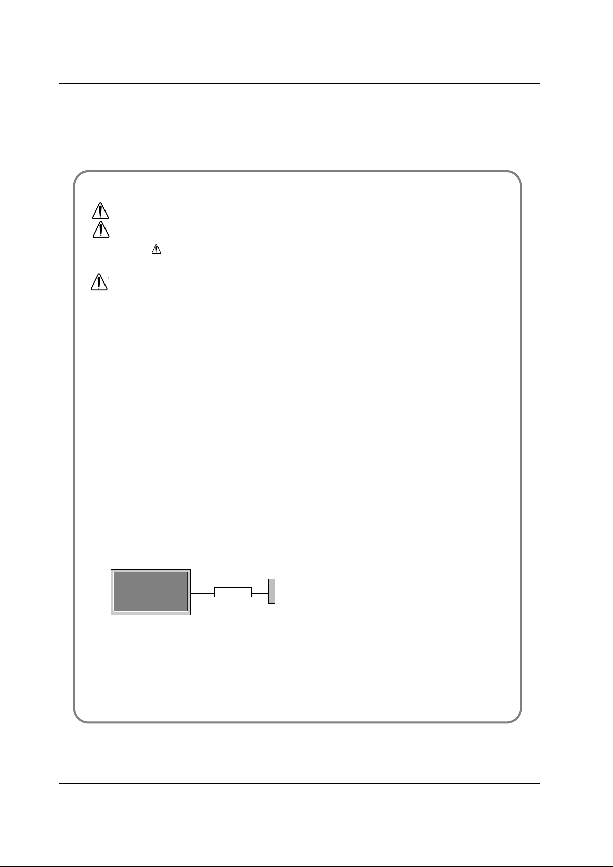
4. Earth wire should be connected.
- If the earth wire is not connected, there is possible a danger
of electric shock caused by the current leakage.
- If grounding methods are not possible, a separate circuit
breaker should be employed and installed by a qualified
electrician.
- Do not connect ground to telephone wires, lightning rods or
gas pipe.
5. Do not placing anything containing liquid on top
of the Monitor.
This may cause a fire or could give an electric shock.
6. Do not insert any object into the exhaust vent.
This may cause a fire or could give an electric shock.
7. Do not place heavy objects on the Monitor.
This may cause serious injury to a child or adult.
8. Do not use water the Monitor while cleaning.
This may cause damaged the Monitor or could give an electric shock.
9. In case of smoke or strange smell from the
Monitor, switch it off ,unplug it from the wall outlet and contact your dealer or service center.
This may cause a fire or could give an electric shock.
10. Do not attempt to service the Monitor yourself.
Contact your dealer or service center.
This may cause damaged the Monitor or could give an electric shock.
11.During a lightning thunder, unplug the Monitor
from the wall outlet and don’t touch an antenna
cable.
This may cause damaged the Monitor or could give an electric shock.
W
W ARNING
*
Safety instructions have two kinds of information, and each meaning of it is as below.
Take care of danger that may happen under specific condition.
The violation of this instruction may cause serious injuries and even death.
The violation of this instruction may cause light injuries or damage of the
product.
WARNING
NOTES
Power
supplier
Short-circuit
breaker
Owner’s Manual 3
Safety Instructions
1. Never touch the power plug with a wet hand.
This may cause an electric shock.
2. Disconnect from the mains and remove all connections before moving.
3. Do not place the Monitor in a built-in installation
such as a bookcase or rack.
Ventilation required.
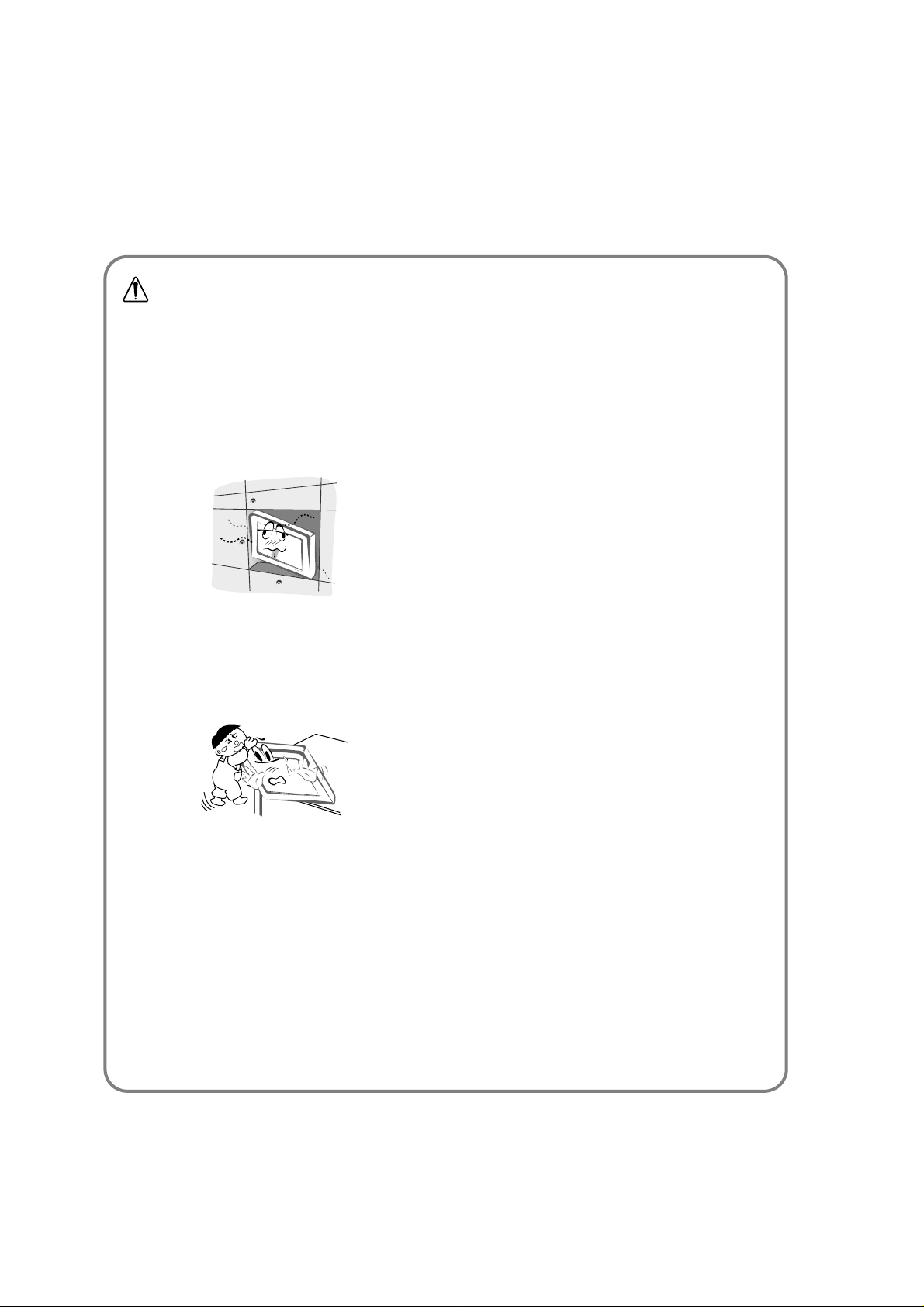
4. When installing the Monitor on a table, be careful
not to place the edge of its stand.
This may cause the Monitor to fall, causing serious injury to a
child or adult, and serious damage to the Monitor.
5. Do not place an outside antenna in the vicinity of
overhead power lines or other electric light or
power circuits.
This may cause an electric shock.
6. There should be enough distance between an outside antenna and power lines to keep the former
from touching the latter even when the antenna
falls.
This may cause an electric shock.
7. Do not pull the cord but the plug when unplugging.
This may cause a fire.
8. Ensure the power cord doesn’t trail across any
hot objects like a heater.
This may cause a fire or an electric shock.
9. Do not plug when the power cord or the plug is
damaged or the connecting part of the power outlet is loose.
This may cause a fire or an electric shock.
10. Dispose of used batteries carefully to protect a
child from eating them.
In case that it eats them, take it to see a doctor immediately.
11. When moving the Monitor assembled with speakers do not carry holding the speakers.
This may cause the Monitor to fall, causing serious injury to a
child or adult, and serious damage to the Monitor.
12. Unplug this product from the wall outlet before
cleaning. Do not use liquid cleaners or aerosol
cleaners.
This may cause damaged the Monitor or could give an electric shock.
13. Contact the service center once a year to clean
the internal part of the Monitor.
Accumulated dust can cause mechanical failure.
14. The distance between eyes and the screen should
be about 5 ~ 7 times as long as diagonal length of
the screen.
If not, eyes will strain.
15. Unplug the Monitor from the wall outlet when it is
left unattended and unused for long periods of
time.
Accumulated dust may cause a fire or an electric shock from
deterioration or electric leakage.
16. Only use the specified batteries.
This make cause damaged the Monitor or could give an electric shock.
NOTE

4 Plasma Monitor
Contents
After reading this manual, keep it handy for future reference.
Safety Instructions . . . . . . . . . . . . . . . . . . . . . . . . . . . . .2~3
Introduction
Controls and Connection Options . . . . . . . . . . . .6
Remote Control Key Functions . . . . . . . . . . . . . .7
Installation
Installation Instruction . . . . . . . . . . . . . . . . . . . .9~10
External Equipment Connections . . . . . . . . . .11~14
VCR Setup . . . . . . . . . . . . . . . . . . . . . . . . . . . .11
Cable TV Setup . . . . . . . . . . . . . . . . . . . . . . . .11
External A/V Source Setup . . . . . . . . . . . . . . . .12
DVD Setup . . . . . . . . . . . . . . . . . . . . . . . . . . . . 12
DTV Setup . . . . . . . . . . . . . . . . . . . . . . . . . . . .12
PC Setup . . . . . . . . . . . . . . . . . . . . . . . . . .13~14
Operation
Turning on the Monitor . . . . . . . . . . . . . . . . . . . . .15
Menu Language Selection . . . . . . . . . . . . . . . . . .15
Picture Menu Options
APC (Auto Picture Control) . . . . . . . . . . . . . . . . 16
Manual Picture Control . . . . . . . . . . . . . . . . . . .16
Auto Color Temperature Control . . . . . . . . . . . .16
Manual Color Temperature Control . . . . . . . . . .16
Sound Menu Options
DASP (Digital Auto Sound Processing) . . . . . . .17
Manual Sound Control . . . . . . . . . . . . . . . . . . .17
AVL(Auto Volume Leveler) . . . . . . . . . . . . . . . .17
Timer Menu Options
Clock Setup . . . . . . . . . . . . . . . . . . . . . . . . . . .18
On/Off Timers Setup . . . . . . . . . . . . . . . . . . . . .18
Auto Off . . . . . . . . . . . . . . . . . . . . . . . . . . . . . .18
Sleep Timer . . . . . . . . . . . . . . . . . . . . . . . . . . .18
Special Menu Options
Key Lock . . . . . . . . . . . . . . . . . . . . . . . . . . . . . 19
ISM Method . . . . . . . . . . . . . . . . . . . . . . . . . . .19
Low power . . . . . . . . . . . . . . . . . . . . . . . . . . . .20
Menu Rotation For Vertical Viewing . . . . . . . . . .20
Screen Menu Options
Auto Adjustment . . . . . . . . . . . . . . . . . . . . . . . .21
Setting Picture Format . . . . . . . . . . . . . . . . . . .21
Picture Size Zoom . . . . . . . . . . . . . . . . . . . . . . 21
Adjusting Horizontal/Vertical Position . . . . . . . .22
Manual Configure . . . . . . . . . . . . . . . . . . . . . . .22
Screen Adjustments . . . . . . . . . . . . . . . . . . . . .22
Initializing . . . . . . . . . . . . . . . . . . . . . . . . . . . . .22
Luminance Noise Reduction . . . . . . . . . . . . . . .23
Selecting Wide VGA mode . . . . . . . . . . . . . . . .23
Split Zoom . . . . . . . . . . . . . . . . . . . . . . . . . . . .23
PIP (Picture-in-Picture) Feature
Watching PIP . . . . . . . . . . . . . . . . . . . . . . . . . .24
Swapping the PIP . . . . . . . . . . . . . . . . . . . . . . .24
Moving the PIP . . . . . . . . . . . . . . . . . . . . . . . . .24
Selecting an Input Signal Source for PIP . . . . . .24
PIP Aspect Ratio . . . . . . . . . . . . . . . . . . . . . . . .24
Double Window Setup Options
Watching Double Window . . . . . . . . . . . . . . . . .25
Sub Picture Size Adjustment . . . . . . . . . . . . . . .25
Swapping the Double Window . . . . . . . . . . . . .25
Selecting a Source for the Double Window . . . .25
External Control Device Setup . . . . . . . . . . . . . . . .26~31
IR Code . . . . . . . . . . . . . . . . . . . . . . . . . . . . . . . . .32~33
Troubleshooting Checklist . . . . . . . . . . . . . . . . . . . . . .34
Specifications . . . . . . . . . . . . . . . . . . . . . . . . . . . . . . . .35
Contents
Contents

Owner’s Manual 5
Introduction
Introduction
Introduction
What is a Plasma Display Panel (PDP)?
If voltage is applied to gas within glass panels, ultraviolet rays are produced and fused with a fluorescent substance. At that
instant, light is emitted. APlasma Display is a next generation flat Display using this phenomenon.
160° - Wide angle range of vision
Your flat panel plasma screen offers an exceptionally broad viewing angle -- over 160 degrees. This means that the display is
clear and visible to viewers anywhere in the room.
Wide Screen
The screen of the Plasma Display is 42" so wide that your viewing experience is as if you are in a theater.
Multimedia
Connect your plasma display to a PC and you can use it for conferencing, games, and internet browsing. The Picture-in-Picture
feature allows you to view your PC and video images simultaneously.
Versatile
The light weight and thin size makes it easy to install your plasma display in a variety of locations where conventional TVs would
not fit.
The PDP Manufacturing Process: Why minute colored dots may be present on the PDP screen
The PDP (Plasma Display Panel) which is the display device of this product is composed of 0.9 to 2.2 million cells. A few cell
defects will normally occur in the PDP manufacturing process. Several minute colored dots visible on the screen should be acceptable. This also occurs in other PDP manufacturers' products and the tiny dots appearing does not mean that this PDP is defective.
Thus a few cell defects are not sufficient cause for the PDP to be exchanged or returned. Our production technology is designed
to minimize cell defects during the manufacture and operation of this product.
Cooling Fan Noise
In the same way that a fan is used in a PC computer to keep the CPU (Central Processing Unit) cool, the PDP is equipped with
cooling fans to cool the Monitor and improve its reliability. Therefore, a certain level of noise could occur while the fans are operating and cooling the PDP.
The fan noise doesn't have any negative effect on the PDP's efficiency or reliability. The noise from these fans is normal during the
operation of this product. We hope you understand that a certain level of noise from the cooling fans is acceptable and is not sufficient cause for the PDP to be exchanged or returned.
WARNING
TO REDUCE THE RISK OF FIRE AND ELECTRIC SHOCK, DO NOT EXPOSE THIS PRODUCT TO
RAIN OR MOISTURE.
6 Plasma Monitor
Introduction
Controls
Controls
Connection Options
Connection Options
R
( )
( )
( )
( )
L
EXPANDED
INPUT
VIDEO
INPUT
RS-232C INPUT
(CONTROL/SERVICE)
EXTERNAL SPEAKER
YPBP
R
(MONO)
R
AUDIO
L
R
AUDIO
L
S-VIDEO
AC INPUT
AUDIO INPUT
AUDIO INPUT
AUDIO INPUT
REMOTE
CONTROL
COMPONENT INPUT
DVI INPUT
RGB INPUT
RGB OUTPUT
1
1. EXTERNAL SPEAKER (8 ohm output)
Connect to optional external speaker(s).
* For further information, refer to ‘Speaker & Speaker
Stand’ manual.
2. RS-232C INPUT (CONTROL/SERVICE) PORT
Connect to the RS-232C port on a PC.
3. DVI (Digital Visual Interface) INPUT/
RGB INPUT/AUDIO INPUT JACKS
Connect the monitor output connector of a PC to the appropriate input port.
4. RGB OUTPUT JACKS
You can watch the RGB signal on another monitor, connect
RGB OUTPUT to another monitor’s PC input port.
5. EXPANDED INPUT
Connect the monitor to the PDP Tuner with the tuner box
cable.
6. COMPONENT INPUT/AUDIO INPUT JACKS
Connect a component video/audio device to these jacks.
7. REMOTE CONTROL
Connect your wired remote control to the remote control
port on the Monitor.
8. S-VIDEO INPUT
Connect S-Video out from an S-VIDEO VCR to the S-VIDEO
input.
AUDIO/VIDEO INPUT JACKS
Connect audio/video out from external equipment to these
jacks.
9. POWER CORD SOCKET
This Monitor operates on an AC power. The voltage is indicated on the Specifications page. Never attempt to operate
the Monitor on DC power.
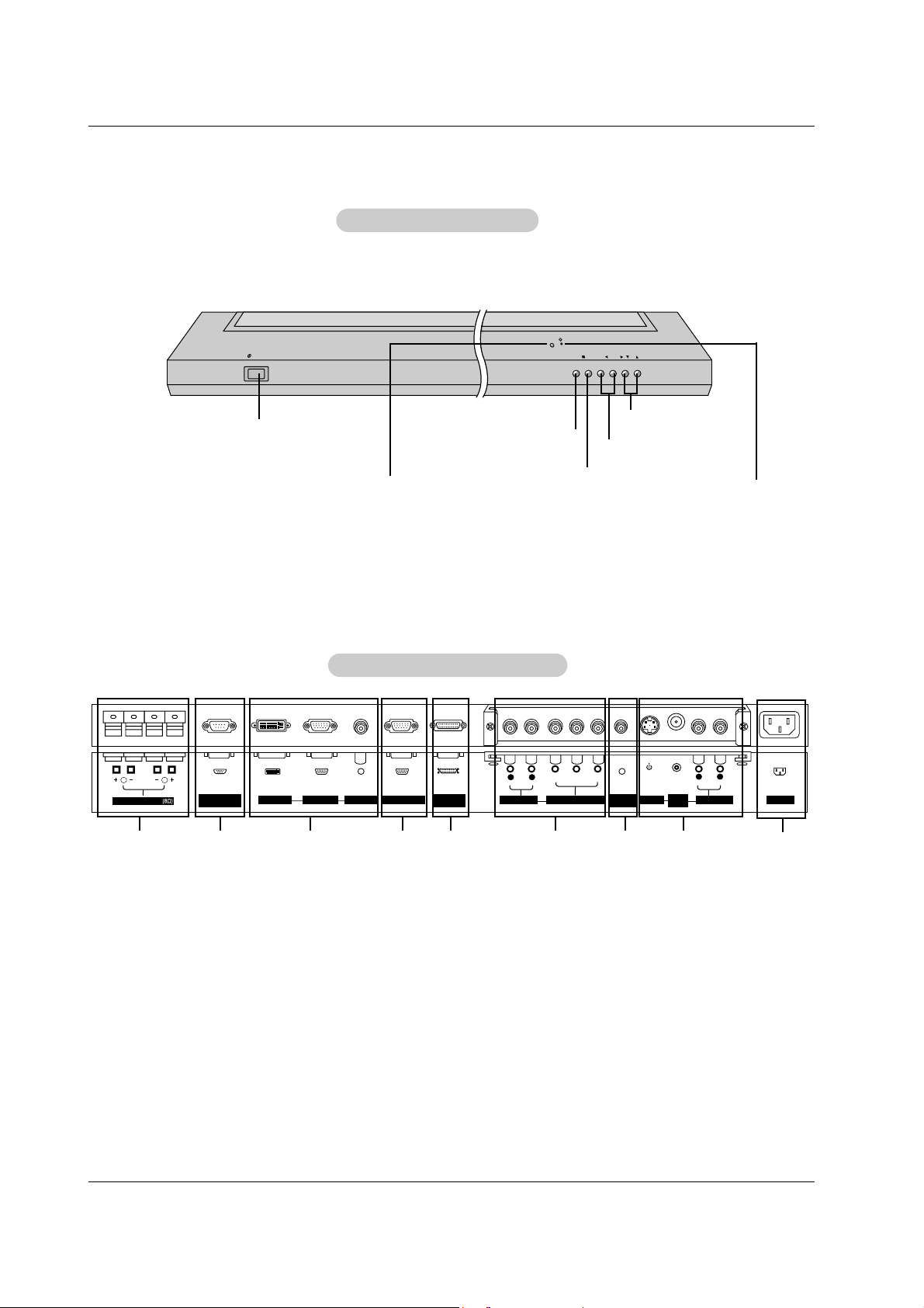
Back Connection Panel
Back Connection Panel
VOL.
MENU
ON/OFF
INPUT
SELECT
Main Power Button
INPUT SELECT Button
VOLUME (F,G) Buttons
Power Standby Indicator
Illuminates red in standby mode,
Illuminates green when the
Monitor is turned on
Remote Control Sensor
MENU Button
E, D Buttons
Front Panel Controls
Front Panel Controls
2 4 5 73 8
9
6
- This is a simplified representation of front panel.
Here shown may be somewhat different from your monitor.
- Connection panels shown may be somewhat different from your monitor.
Owner’s Manual 7
Introduction
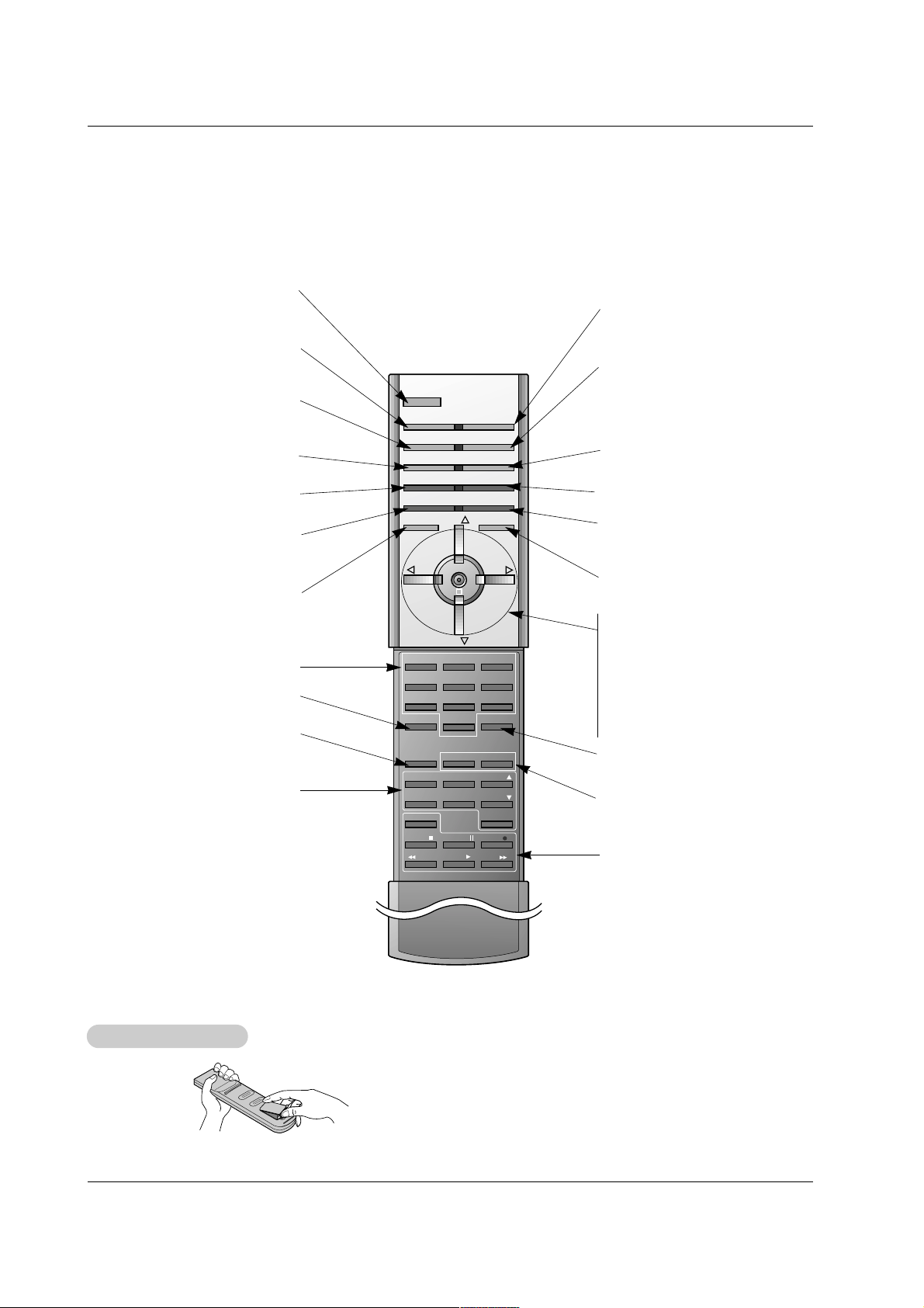
Remote Control Key Functions
Remote Control Key Functions
- When using the remote control, aim it at the remote control sensor on the monitor.
- Under certain conditions such as if the remote IR signal is interrupted, the remote control may not function. Press the key again
as necessary.
• Open the battery compartment cover on the back side and
insert the batteries with correct polarity.
• Install two 1.5V batteries of AAA type. Don’t mix used batteries
with new batteries.
Installing Batteries
Installing Batteries
123
456
7809
POWER
MULTIMEDIA INPUT SELECT
APC DASP
ARC SLEEP
PIP
DW
SWAP
MENU MUTE
ENTER
VOL
POWER
STOP
FF
REC
PLAY
REW
P/STILL
WIN.SIZE
WIN.POSITION
FAV CH
CAPTION
A.PROG PIP CH
PIP CH
ZOOM +
MTS
ZOOM -
SPLIT ZOOM
MEMORY/ERASE
VOL
CH
CH
PIP INPUT
POWER
Switches the monitor between
ON and STANDBY.
MULTIMEDIA
Selects:
Component, RGB, or DVI
mode.
APC
Adjusts the factory preset picture
according to the room.
ARC
Changes the picture format.
PIP
Switches the sub picture on and off.
SWAP
Exchanges main and sub picture
images.
MENU
Displays on screen menus.
Exits the current menu.
ENTER
CH
D / E
(Channel button)
Selects menu options.
VOL F / G (Volume button)
Increases/decreases sound level.
Adjusts menu settings.
INPUT SELECT
Selects source:
Video, S-Video,
Component, RGB, or DVI mode.
DASP
Selects the sound appropriate to
your viewing program character:
Flat, Music, Movie, Sports, or
User.
SLEEP
Sets the sleep timer.
PIP INPUT
Selects the input mode for the sub
picture.
MUTE
Switches the sound on or off.
ZOOM-/ZOOM+
Enlarges or reduces the main picture
size.
DW (Double Window)
Selects Double Window mode.
WIN. SIZE
Adjusts the sub picture size.
WIN.POSITION
Moves the sub picture.
NUMBER buttons
Not functional
VCR BUTTONS
Control some LG video cassette
recorders.
SPLIT ZOOM
Enlarge the screen with regular
ration.
8 Plasma Monitor
Installation
Installation
Installation
D-sub 15 pin cable
Owner’s Manual
1.5V
1.5V
Batteries
BNC-RCA adapter
Power Cord
123
456
7809
POWER
SLEEP INPUT SELECT
APC DASP
ARC PIP ARC
PIP
TWIN PICTURE
SWAP
MENU MUTE
OK
VOL
POWER STOP
PLAY FF
REC
REW
P/STILL
WIN.SIZE
WIN.POSITION
ZOOM +
ZOOM -
SPLIT ZOOM
VOL
SUB INPUT
Remote Control
DVI-D Cable
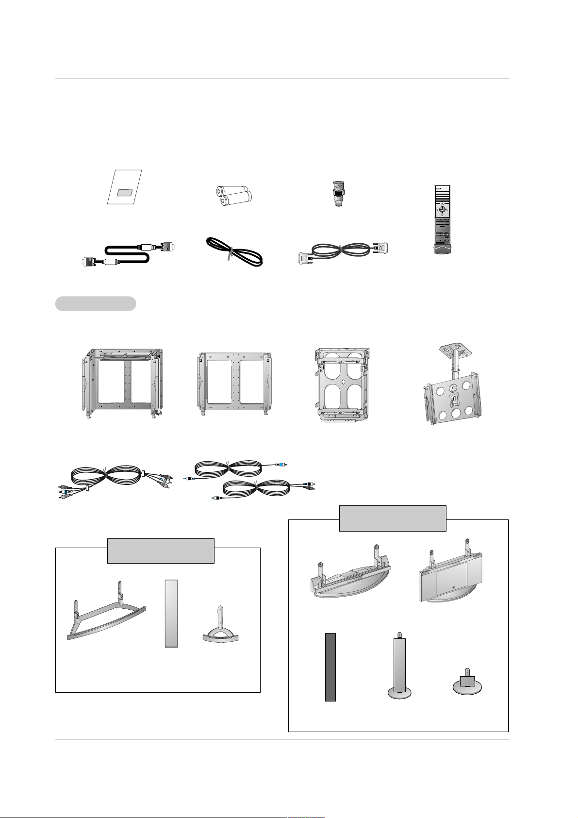
Ensure that the following accessories are included with your plasma display. If an accessory is missing, please contact the dealer
where you purchased the product.
Video cables
Audio cables
Ceiling mounting bracket
- Optional extras can be changed or modified for quality improvement without any notification new optional extras can be added.
- Contract your dealer for buying these items.
Option Extras
Option Extras
Tilt wall mounting bracket
Wall mounting bracket
Vertical wall mounting bracket
(MP-42PZ45M/45V/91M/91V
series models only)
Desktop stand
Desktop
Speaker stand
Speakers
MP-42PZ44/44H/45M/45V
series models only
Desktop stand
Floor type stand
Floor type
Speaker stand
Desktop
Speaker stand
Speakers
MP-42PZ90/90H/91M/91V
series models only
Owner’s Manual 9
Installation
Installation Instructions
Installation Instructions
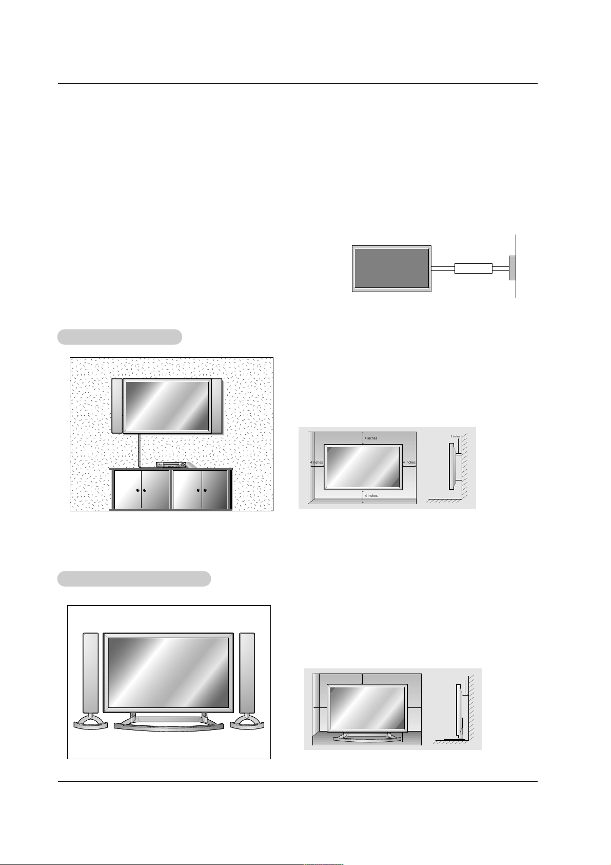
• The Monitor can be installed in different ways such as on a wall, or on a desktop etc.
• Install this monitor only in a location where adequate ventilation is available.
• It is recommended that MP-42PZ44/45V/90/91V series models only be used at an altitude of less than 3281 feet (1000m)
to get the best quality picture and sound.
• It is recommended that MP-42PZ44H/45M/90H/91M series models only be used at an altitude of less than 6561 feet (2000m)
to get the best quality picture and sound.
GROUNDING
Ensure that you connect the grounding / earth wire to prevent possible
electric shock. If grounding methods are not possible, have a qualified
electrician install a separate circuit breaker. Do not try to ground the
unit by connecting it to telephone wires, lightening rods, or gas pipes.
Power
Supply
Short-circuit
Breaker
WWall Mount Installation
all Mount Installation
For proper ventilation, allow a clearance of 4” on each
side and 2” from the wall. Detailed installation instructions are included from your dealer in the optional Wall
Mounting Bracket Installation and Setup Guide.
Desktop Pedestal Installation
Desktop Pedestal Installation
For proper ventilation, allow a clearance of 4” on each
side and the top, 2.36” on the bottom, and 2” from the
wall. Detailed installation instructions are included in the
optional Desktop Stand Installation and Setup Guide, see
your dealer.
4 inches
4 inches
2 inches
4 inches4 inches
2 inches
4 inches
4 inches
4 inches
2.36 inches
10 Plasma Monitor
Installation
Installation Instructions continued
Installation Instructions continued
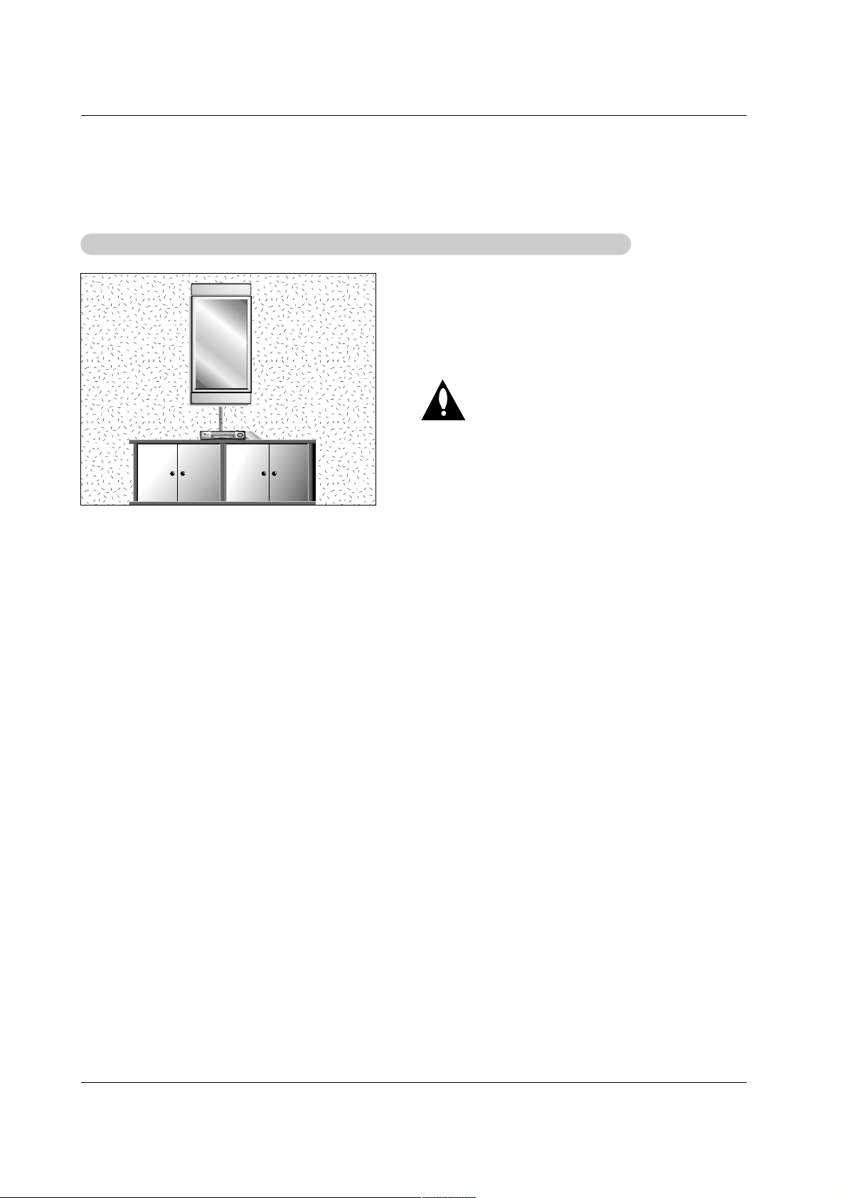
WWall Mount: V
all Mount: V
ertical installation (MP-42PZ45M/45V/91M/91V series models only)
ertical installation (MP-42PZ45M/45V/91M/91V series models only)
Detailed installation instructions are included in the
optional Vertical Wall Mounting Bracket Installation and
Setup Guide, see your dealer.
NOTE: When installing the monitor vertically, the front
panel controls must be in the left side position.
When installing the monitor vertically, you
have to change the OSD (On Screen Display)
display mode so that the menus will appear
correctly and also to protect the monitor from
overheating (Refer to P. 20).
Owner’s Manual 11
Installation
External Equipment Connections
External Equipment Connections
NOTE: All cables shown are not included with the plasma display.
- To avoid picture noise (interference), leave an adequate distance between the VCR and Monitor
- Use the ISM Method feature to avoid having a fixed image remain on the screen for a long period of time. Typically a frozen still
picture from a VCR. If the 4:3 picture format is used; the fixed image may remain visible on the screen.
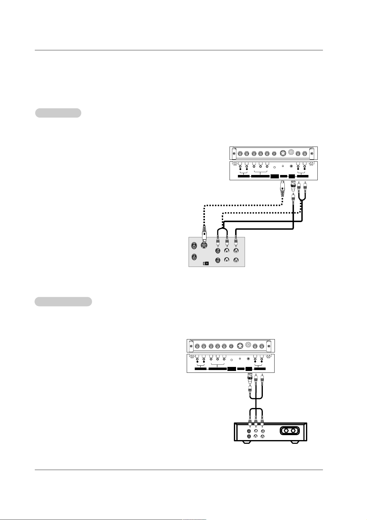
How to connect
1. Connect the provided BNC-RCA adapter to the monitor’s
VIDEO INPUT.
2. Connect the audio and video cables from the VCR's output
jacks to the monitor input jacks, as shown in the figure. When
connecting the monitor to a VCR, match the jack colors: (Video
= yellow, Audio Left = white, and Audio Right = red).
Mono VCR: Connect the video output cable from the VCR to
the VIDEO input on the monitor.
S-VIDEO VCR: Connect the S-Video output cable from the
VCR to the S-VIDEO input. (Note that S-Video yields higher
quality video).
How to use
1. Insert a video tape into the VCR and press PLAY on the VCR.
(Refer to the VCR owner’s manual.)
2. Use the INPUT SELECT button on the remote control to select
Video.
(If connected to S-VIDEO, select the S-Video external input
source.)
VCR Setup
VCR Setup
- After subscribing to a cable TV service from a local provider and installing a converter, you can watch cable TV programming.
The monitor cannot display TV programming unless a TV tuner device or cable TV converter box is connected to the Monitor.
- For further information regarding cable TV service, contact your local cable TV service provider(s).
How to connect
1. Connect the provided BNC-RCA adapter to the monitor’s
VIDEO INPUT.
2. Connect the audio and video cables from the cable box's out-
put jacks to the monitor input jacks, as shown in the figure.
When connecting the monitor to a cable TV, match the jack
colors (Video = yellow, Audio Left = white, and Audio Right =
red).
How to use
1. Use the INPUT SELECT button on the remote control to
select Video.
2. Select your desired channel with the cable box remote control.
Cable
Cable
TV Setup
TV Setup
S-VIDEO
OUT
IN
(R) AUDIO (L) VIDEO
VIDEO
INPUT
YPBP
R
(MONO)
R
AUDIO
L
R
AUDIO
L
S-VIDEO AUDIO INPUT
AUDIO INPUT
REMOTE
CONTROL
COMPONENT INPUT
VCR
TV
VCR
RF Cable
(R) AUDIO (L) VIDEO
VIDEO
INPUT
YPBP
R
(MONO)
R
AUDIO
L
R
AUDIO
L
S-VIDEO AUDIO INPUT
AUDIO INPUT
REMOTE
CONTROL
COMPONENT INPUT
Cable Box
 Loading...