

LG MonoX ACe, MonoX ACe A1C-B3 Series Troubleshooting Manual
LGxxxA1C-B3
Troubleshooting Guide
Perfect
AC
TM
Module
The Difference is in the Detail
2
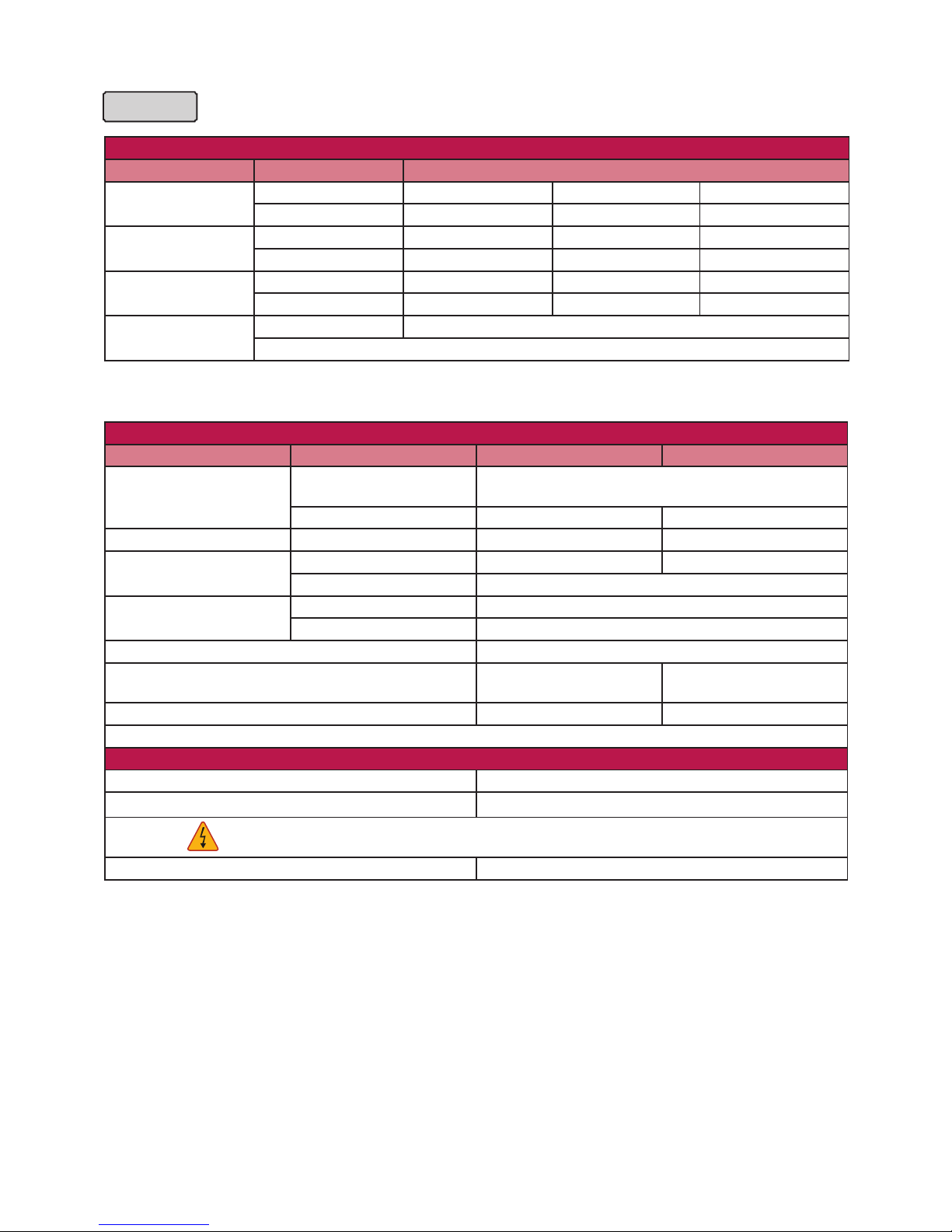
Product Specifications
AC module
DC Input
Parameter Section Value
Power
Max. 295 W 300W 305W
Tolerance 3 % 3 % 3 %
Voltage
Open Circuit 39.7 V 39.8 V 40.0 V
Max. Power Point 31.8 V 32.0 V 32.1 V
Current
Short Circuit 9.85 A 9.98 A 10.10 A
Max. Power Point 9.28 A 9.40 A 9.52 A
Efciency
Relative Reduction < 2.0%
Note : *Relative efciency reduction in respect to irradiance
Note : Rated electrical characteristics are within 10 percent of above figures.
PV module was measured at STC (Standard Test Condition : Irradiation 1,000W/m2, Cell temp. 77°F(25°C), 1,5AM)
AC Output
Parameter Section 240VAC 208VAC
Power
AC Continuous
1)
280W (@DC Module 295W) / 285W (@DC Module
300W) / 290W (@DC Module 305W)
Inverter Rated Continuous 305W 300W
Voltage Rated 240V (211 ~ 264 V) 208V (187 ~ 229V)
Current
Rated 1.27A 1.44A
Max. Fault Current 77A
Efciency
Nominal 60 Hz (59.3 ~ 60.5 Hz)
Extended 57.0 Hz ~ 60.5 Hz
Power Factor > 0.95
CEC Weighted Efciency
(California Energy Commission)
96.5% 96.0%
Max. Number of AC Modules 12 ea 11ea
1)
Pmax (AC) = Max. Input DC Power x CEC Efciency
Protection
Ground Fault Detection and Interrupt (GFDI) Applied
Fuse 2A
CAUTION : FOR CONTINUED PROTECTION AGAINST THE RISK OF FIRE,
REPLACE ONLY WITH SAME TYPE AND RATING OF FUSE
Over Current Protection Device (OCPD) 20A
3
AC module
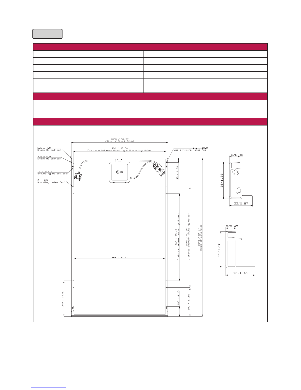
Mechanical Data
Micro Inverter Model (Utility Interactive) LM305UE-G1
Enclosure Rating Type 6
Operating Ambient Temperature - 40 ~ 65 °C (-40 ~ 145°F)
Operating Temperature (internal) - 40 ~ 90 °C (-40 ~ 194°F)
Storage Temperature - 40 ~ 90 °C (-40 ~ 194°F)
Weight 18.0 kg
Certication
UL 1703, IEC 61215 Ed 2, IEC 61730 Safety Class II, CE, ISO9001
UL1741 / IEEE1547 CSA 22.2 No. 107.1-01
FCC Part 15 Class B
Dimension
Unit: mm / in.
Cross-sectional Drawings
Short Side Frame
Long side frame
4
IEEE 1547 (Default)
Parameter Range Clearing Time (s)
Phase Voltage V < 60V <0.16
Voltage
60V ≤ V < 106V < 2.00
132 ≤ V < 144V < 1.00
V ≥ 144V < 0.16 (< 0.016, Hawaii mode - TOV)
1)
Frequency
> 60.5Hz < 0.16
< 59.3Hz (< 57 Hz,
Hawaii mode)
1)
< 0.16
Note 1 : This test is performed in nominal conditions, except for test parameter
Note 2 : After clearing, if grid returns to the normal state, it takes up to 5 minutes for operation of AC module
Response to Abnormal Conditions
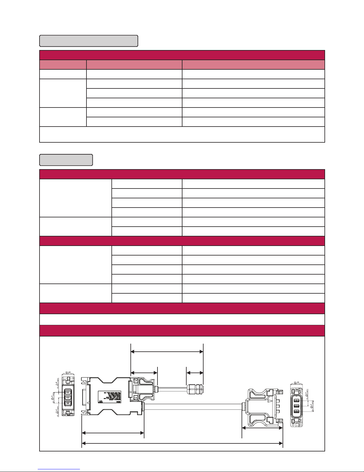
Dedicated Cables
Trunk
Cable
Type TC-ER sunlight resistant
Max. Voltage 600V
Max. Current 20A
Size 12AWG
Connector
Max. Voltage 300V
Max. Current 20A
Drop
Cable
Type TC-ER sunlight resistant
Max. Voltage 600V
Max. Current 5A
Size 18AWG
Connector
Max. Voltage 300V
Max. Current 5A
Certication
UL9703, UL6703A
Dimensions
400 mm
(95.75 inch)
53 mm
(2.09 inch)
122 mm
(4.80 inch)
1,200 mm
(47.24 inch)
66 mm
(2.60 inch)
31.5 mm
(1.24 inch)

5
Table of Contents
Product Specifications 2
1 Safety 6
2 Messages and Alerts
1-1 APP Messages 8
Notice #1 and #2 AC Voltage High/ Low 9
Notice #3 AC Frequency Changing Too Fast 11
Notice #4, #5 AC Frequency High/ Low 11
Error #1 DC Voltage High 12
Error #2 DC Current High 12
Error #3 AC Current High 13
Error #4 Inverter Failure 13
Error #5 Temperature Protection 14
Alert GFDI 14
3
Gateway and Communication Issues
3-1 Power Line Communication Issues 15
3-1-1 Factors that Affect Power Line Communication 15
3-1-2 Cautions during Gateway Installation 16
3-1-3 Problems Checking AC Module through the Smartphone App 16
3-1-4 Discrepancy of Installed AC Module Quantity on Smartphone App 16
3-1-5 Number of Registered AC Modules Fluctuating on Smartphone App 16
3-1-6 Checking for Interferences to the Power Line Communication 17
3-1-7 Connecting the Gateway to a Remote Router 18
3-1-8 Solving Connection Issues in the Gateway 18
3-1-9 Registering Additional AC Modules to the Gateway 19
3-1-10 Changing the EnerBox 19
3-1-11 Registering a Replacement AC Module to the Gateway 20
3-1-12 Relocating a Gateway with Completed AC Module Registration 20
4 Gateway and Communication Issues
4-1 Network Configuration Troubleshooting 21
6
1 Safety
Note and comply with the safety guidelines of this manual while handling AC modules. Failure to comply may
result in severe damage to the equipment and/or fatal injuries.
Safety symbols are used to minimize loss and injury during handling and operation of the equipment specified in
this manual.
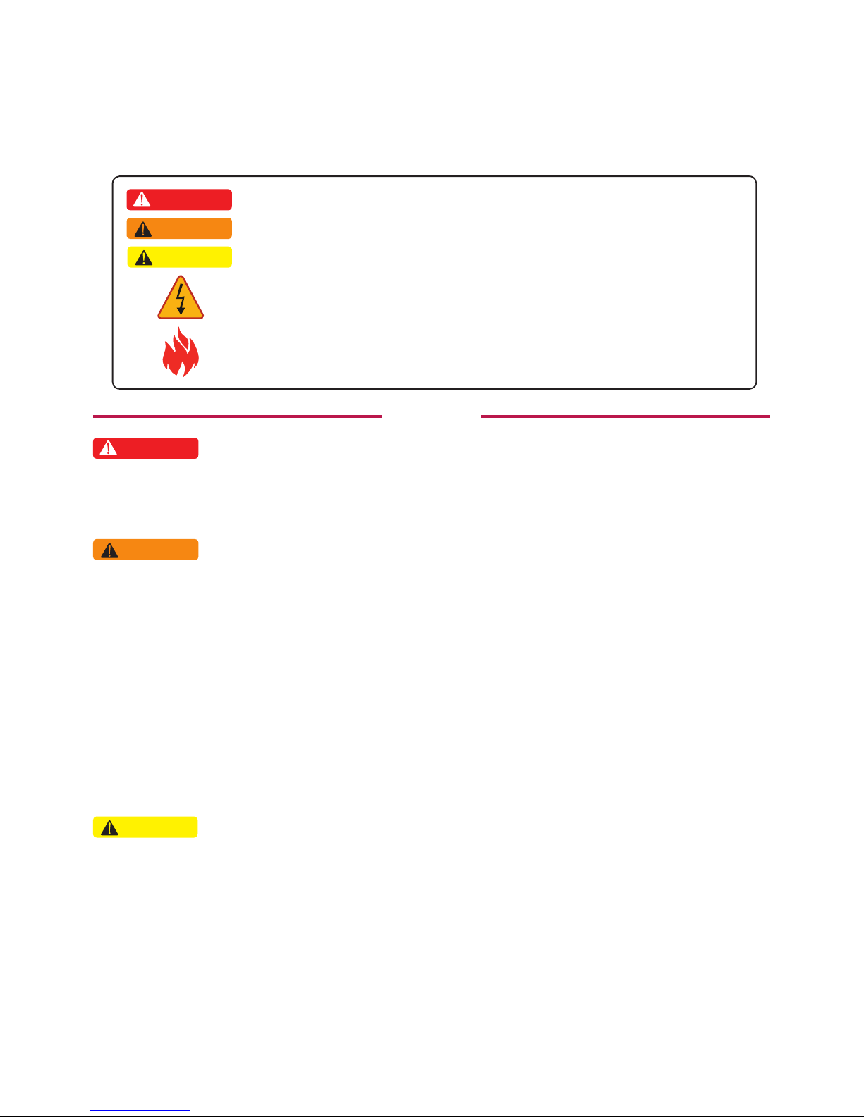
1-1 Safety Symbols
WARNING
• To prevent the risk of burns, do not touch metal parts during operation.
• For safety, only qualified persons should service modules.
• To prevent the risk of electric shock, stay away from damaged module(s). Do not use module(s) with broken
glass or torn backsheets.
• Damaged modules must be handled with proper safety equipment. Failure to comply may result in serious bodily
injury or death.
• For proper operation, make sure to use exclusively cables, connectors and accessories provided by LG
Electronics. Parts that are not listed may cause critical danger.
• For proper operation, the AC Module shall be connected only to a dedicated branch circuit.
• To prevent the risk of fire, do not connect any device between the AC module and circuit breaker. Circuit breaker
may not work properly.
• Before installation, make sure to check that the area of location meets the required environment specified in
Chapter 6. Product Specification (Voltage, frequency, temperature, number of AC modules, overcurrent
device).
DANGER
• To prevent the risk of electric shock, stay away from current-carrying terminals during operation. And, allow
several minutes after the circuit breaker has been turned off. It may be energized in the open position.
• To prevent the risk of overvoltage, do not disconnect the cable connector during operation.
• Use proper equipment, connectors, wires and buttresses for the installation of the module. Failure to comply may
result in product damage, product failure and/or bodily injury.
• To reduce the risk of accidents, do not install during inclement weather.
• To prevent the risk of electric shock, do not touch the glass surface or frame of the solar module after installation.
• To prevent the risk of injury, do not apply pressure on the module (ex. placing heavy objects or stepping on the
module).
• To prevent the risk of injury, do not drop the module; modules must be gently handled and placed down.
• For proper operation, do not scratch the coating surface of the frame. It may increase the corrosion of the frame.
• For proper operation, do not concentrate sunlight on the module surface.
• Addition of holes in the frame or glass of the module may decrease the strength and integrity of the frame or
glass.
• Do not remove warning labels.
• Store the module in its original package until installation.
CAUTION
Failure to comply with the instructions may cause fatal injuries or immediate death.
DANGER
Failure to comply with the instructions may cause severe injuries or death.
WARNING
Failure to comply with the instructions may cause injuries or damage to property.
Failure to comply with the instructions may cause severe injuries or immediate death
by overvoltage.
Failure to comply with the instructions may cause injuries or damage to property by fire.
CAUTION
AC Module

7
WARNING
• EnerBox warranty void if cover removed. No serviceable parts inside. Refer servicing to qualified personnel.
• To avoid communication interference, do not connect the product to power strips, surge protectors, or surge
protector-embedded power strips. It is recommended to directly connect the gateway to a120VAC outlet.
• Only certified installers should enter the installer mode.PV system may malfunction.
• Set the grid configuration to best suit the installation area. PV system may malfunction.
CAUTION
Gateway
8
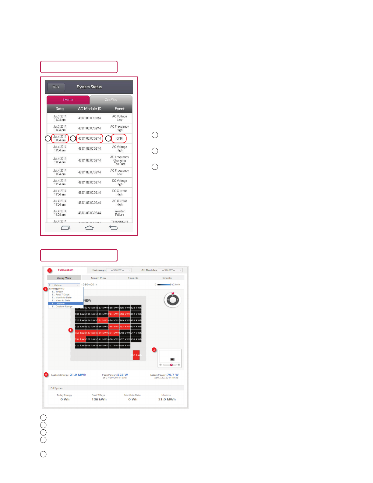
Ex) App Messages Screen
Ex) Web Array View Screen
1
Date
2
AC module ID
3
Message type
1 2 3
The app shows real time status of the AC modules under AC Module Status and System Status, as well as Array
View and Events through the monitoring web server. Please refer AC module System Installation Instruction
and AC Module Web Server Manual for further details.
2 Messages and Alerts
1
Select monitoring levels. (ex. Full System, by Gateway or individual AC Module)
2
Set the monitoring period. (Today, Past 7 Days, Month, etc.)
3
Installer scan zoom in or out of the screen.
4
If the module is red, maintenance is required.
Click the red module to see more details.
5
Installer can check today’s production information in this area.
(System Energy, Peak Power and Latest Power)
 Loading...