

Page 1

LCD TV
SERVICE MANUAL
CAUTION
BEFORE SERVICING THE CHASSIS,
READ THE SAFETY PRECAUTIONS IN THIS MANUAL.
CHASSIS : ML-042A
MODEL: 15LW1R (15LW1R-MD)
website:http://biz.LGservice.com
e-mail:http://www.LGEservice.com/techsup.html
Page 2

- 2 -
CONTENTS
CONTENTS .............................................................................................. 2
PRODUCT SAFETY ..................................................................................3
SPECIFICATION........................................................................................6
DISASSEMBLY..........................................................................................9
SERVICE TEST PROGRAM....................................................................11
TROUBLE SHOOTING............................................................................16
BLOCK DIAGRAM...................................................................................25
WIRING DIAGRAM..................................................................................30
EXPLODED VIEW .................................................................................. 31
REPLACEMENT PARTS LIST ............................................................... 35
SVC. SHEET ...............................................................................................
Page 3

- 3 -
SAFETY PRECAUTIONS
Many electrical and mechanical parts in this chassis have special safety-related characteristics. These parts are identified by in the
Schematic Diagram and Replacement Parts List.
It is essential that these special safety parts should be replaced with the same components as recommended in this manual to prevent
X-RADIATION, Shock, Fire, or other Hazards.
Do not modify the original design without permission of manufacturer.
General Guidance
An isolation Transformer should always be used during the
servicing of a receiver whose chassis is not isolated from the AC
power line. Use a transformer of adequate power rating as this
protects the technician from accidents resulting in personal injury
from electrical shocks.
It will also protect the receiver and it's components from being
damaged by accidental shorts of the circuitry that may be
inadvertently introduced during the service operation.
If any fuse (or Fusible Resistor) in this TV receiver is blown,
replace it with the specified.
When replacing a high wattage resistor (Oxide Metal Film Resistor,
over 1W), keep the resistor 10mm away from PCB.
Keep wires away from high voltage or high temperature parts.
X-RAY Radiation
Warning:
To determine the presence of high voltage, use an accurate high
impedance HV meter.
Adjust brightness, color, contrast controls to minimum.
Measure the high voltage.
The meter reading should indicate
23.5 ¡ 1.5KV: 14-19 inch, 26 ¡ 1.5KV: 19-21 inch,
29.0 ¡ 1.5KV: 25-29 inch, 30.0 ¡ 1.5KV: 32 inch
If the meter indication is out of tolerance, immediate service and
correction is required to prevent the possibility of premature
component failure.
Before returning the receiver to the customer,
always perform an AC leakage current check on the exposed
metallic parts of the cabinet, such as antennas, terminals, etc., to
be sure the set is safe to operate without damage of electrical
shock.
Leakage Current Cold Check(Antenna Cold Check)
With the instrument AC plug removed from AC source, connect an
electrical jumper across the two AC plug prongs. Place the AC
switch in the on position, connect one lead of ohm-meter to the AC
plug prongs tied together and touch other ohm-meter lead in turn to
each exposed metallic parts such as antenna terminals, phone
jacks, etc.
If the exposed metallic part has a return path to the chassis, the
measured resistance should be between 1MΩ and 5.2MΩ.
When the exposed metal has no return path to the chassis the
reading must be infinite.
An other abnormality exists that must be corrected before the
receiver is returned to the customer.
Leakage Current Hot Check (See below Figure)
Plug the AC cord directly into the AC outlet.
Do not use a line Isolation Transformer during this check.
Connect 1.5K/10watt resistor in parallel with a 0.15uF capacitor
between a known good earth ground (Water Pipe, Conduit, etc.)
and the exposed metallic parts.
Measure the AC voltage across the resistor using AC voltmeter
with 1000 ohms/volt or more sensitivity.
Reverse plug the AC cord into the AC outlet and repeat AC voltage
measurements for each exposed metallic part. Any voltage
measured must not exceed 0.75 volt RMS which is corresponds to
0.5mA.
In case any measurement is out of the limits specified, there is
possibility of shock hazard and the set must be checked and
repaired before it is returned to the customer.
Leakage Current Hot Check circuit
The source of X-RAY RADIATION in this TV receiver is the High
Voltage Section and the LCD PANEL.
For continued X-RAY RADIATION protection, the replacement
panel must be the same type panel as specified in the
Replacement Parts List.
IMPORTANT SAFETY NOTICE
0.15uF
To Instrument's
exposed
METALLIC PARTS
AC Volt-meter
1.5 Kohm/10W
Good Earth Ground
such as WATER PIPE,
CONDUIT etc.
Page 4

- 4 -
CAUTION: Before servicing receivers covered by this service
manual and its supplements and addenda, read and follow the
SAFETY PRECAUTIONS on page 3 of this publication.
NOTE: If unforeseen circumstances create conflict between the
following servicing precautions and any of the safety precautions on
page 3 of this publication, always follow the safety precautions.
Remember: Safety First.
General Servicing Precautions
1. Always unplug the receiver AC power cord from the AC power
source before;
a. Removing or reinstalling any component, circuit board
module or any other receiver assembly.
b. Disconnecting or reconnecting any receiver electrical plug or
other electrical connection.
c. Connecting a test substitute in parallel with an electrolytic
capacitor in the receiver.
CAUTION: A wrong part substitution or incorrect polarity
installation of electrolytic capacitors may result in an
explosion hazard.
2. Test high voltage only by measuring it with an appropriate high
voltage meter or other voltage measuring device (DVM,
FETVOM, etc) equipped with a suitable high voltage probe.
Do not test high voltage by "drawing an arc".
3. Do not spray chemicals on or near this receiver or any of its
assemblies.
4. Unless specified otherwise in this service manual, clean
electrical contacts only by applying the following mixture to the
contacts with a pipe cleaner, cotton-tipped stick or comparable
non-abrasive applicator; 10% (by volume) Acetone and 90% (by
volume) isopropyl alcohol (90%-99% strength)
CAUTION: This is a flammable mixture.
Unless specified otherwise in this service manual, lubrication of
contacts in not required.
5. Do not defeat any plug/socket B+ voltage interlocks with which
receivers covered by this service manual might be equipped.
6. Do not apply AC power to this instrument and/or any of its
electrical assemblies unless all solid-state device heat sinks are
correctly installed.
7. Always connect the test receiver ground lead to the receiver
chassis ground before connecting the test receiver positive
lead.
Always remove the test receiver ground lead last.
8. Use with this receiver only the test fixtures specified in this
service manual.
CAUTION: Do not connect the test fixture ground strap to any
heat sink in this receiver.
Electrostatically Sensitive (ES) Devices
Some semiconductor (solid-state) devices can be damaged easily
by static electricity. Such components commonly are called
Electrostatically Sensitive (ES) Devices. Examples of typical ES
devices are integrated circuits and some field-effect transistors and
semiconductor "chip" components. The following techniques
should be used to help reduce the incidence of component
damage caused by static by static electricity.
1. Immediately before handling any semiconductor component or
semiconductor-equipped assembly, drain off any electrostatic
charge on your body by touching a known earth ground.
Alternatively, obtain and wear a commercially available
discharging wrist strap device, which should be removed to
prevent potential shock reasons prior to applying power to the
unit under test.
2. After removing an electrical assembly equipped with ES
devices, place the assembly on a conductive surface such as
aluminum foil, to prevent electrostatic charge buildup or
exposure of the assembly.
3. Use only a grounded-tip soldering iron to solder or unsolder ES
devices.
4. Use only an anti-static type solder removal device. Some solder
removal devices not classified as "anti-static" can generate
electrical charges sufficient to damage ES devices.
5. Do not use freon-propelled chemicals. These can generate
electrical charges sufficient to damage ES devices.
6. Do not remove a replacement ES device from its protective
package until immediately before you are ready to install it.
(Most replacement ES devices are packaged with leads
electrically shorted together by conductive foam, aluminum foil
or comparable conductive material).
7. Immediately before removing the protective material from the
leads of a replacement ES device, touch the protective material
to the chassis or circuit assembly into which the device will be
installed.
CAUTION: Be sure no power is applied to the chassis or circuit,
and observe all other safety precautions.
8. Minimize bodily motions when handling unpackaged
replacement ES devices. (Otherwise harmless motion such as
the brushing together of your clothes fabric or the lifting of your
foot from a carpeted floor can generate static electricity
sufficient to damage an ES device.)
General Soldering Guidelines
1. Use a grounded-tip, low-wattage soldering iron and appropriate
tip size and shape that will maintain tip temperature within the
range or 500
O
F to 600OF.
2. Use an appropriate gauge of RMA resin-core solder composed
of 60 parts tin/40 parts lead.
3. Keep the soldering iron tip clean and well tinned.
4. Thoroughly clean the surfaces to be soldered. Use a mall wirebristle (0.5 inch, or 1.25cm) brush with a metal handle.
Do not use freon-propelled spray-on cleaners.
5. Use the following unsoldering technique
a. Allow the soldering iron tip to reach normal temperature.
(500
O
F to 600OF)
b. Heat the component lead until the solder melts.
c. Quickly draw the melted solder with an anti-static, suction-
type solder removal device or with solder braid.
CAUTION: Work quickly to avoid overheating the
circuitboard printed foil.
6. Use the following soldering technique.
a. Allow the soldering iron tip to reach a normal temperature
(500
O
F to 600OF)
b. First, hold the soldering iron tip and solder the strand against
the component lead until the solder melts.
c. Quickly move the soldering iron tip to the junction of the
component lead and the printed circuit foil, and hold it there
only until the solder flows onto and around both the
component lead and the foil.
CAUTION: Work quickly to avoid overheating the circuit
board printed foil.
d. Closely inspect the solder area and remove any excess or
splashed solder with a small wire-bristle brush.
SERVICING PRECAUTIONS
Page 5

- 5 -
IC Remove/Replacement
Some chassis circuit boards have slotted holes (oblong) through
which the IC leads are inserted and then bent flat against the
circuit foil. When holes are the slotted type, the following technique
should be used to remove and replace the IC. When working with
boards using the familiar round hole, use the standard technique
as outlined in paragraphs 5 and 6 above.
Removal
1. Desolder and straighten each IC lead in one operation by gently
prying up on the lead with the soldering iron tip as the solder
melts.
2. Draw away the melted solder with an anti-static suction-type
solder removal device (or with solder braid) before removing the
IC.
Replacement
1. Carefully insert the replacement IC in the circuit board.
2. Carefully bend each IC lead against the circuit foil pad and
solder it.
3. Clean the soldered areas with a small wire-bristle brush.
(It is not necessary to reapply acrylic coating to the areas).
"Small-Signal" Discrete Transistor
Removal/Replacement
1. Remove the defective transistor by clipping its leads as close as
possible to the component body.
2. Bend into a "U" shape the end of each of three leads remaining
on the circuit board.
3. Bend into a "U" shape the replacement transistor leads.
4. Connect the replacement transistor leads to the corresponding
leads extending from the circuit board and crimp the "U" with
long nose pliers to insure metal to metal contact then solder
each connection.
Power Output, Transistor Device
Removal/Replacement
1. Heat and remove all solder from around the transistor leads.
2. Remove the heat sink mounting screw (if so equipped).
3. Carefully remove the transistor from the heat sink of the circuit
board.
4. Insert new transistor in the circuit board.
5. Solder each transistor lead, and clip off excess lead.
6. Replace heat sink.
Diode Removal/Replacement
1. Remove defective diode by clipping its leads as close as
possible to diode body.
2. Bend the two remaining leads perpendicular y to the circuit
board.
3. Observing diode polarity, wrap each lead of the new diode
around the corresponding lead on the circuit board.
4. Securely crimp each connection and solder it.
5. Inspect (on the circuit board copper side) the solder joints of
the two "original" leads. If they are not shiny, reheat them and if
necessary, apply additional solder.
Fuse and Conventional Resistor
Removal/Replacement
1. Clip each fuse or resistor lead at top of the circuit board hollow
stake.
2. Securely crimp the leads of replacement component around
notch at stake top.
3. Solder the connections.
CAUTION: Maintain original spacing between the replaced
component and adjacent components and the circuit board to
prevent excessive component temperatures.
Circuit Board Foil Repair
Excessive heat applied to the copper foil of any printed circuit
board will weaken the adhesive that bonds the foil to the circuit
board causing the foil to separate from or "lift-off" the board. The
following guidelines and procedures should be followed whenever
this condition is encountered.
At IC Connections
To repair a defective copper pattern at IC connections use the
following procedure to install a jumper wire on the copper pattern
side of the circuit board. (Use this technique only on IC
connections).
1. Carefully remove the damaged copper pattern with a sharp
knife. (Remove only as much copper as absolutely necessary).
2. carefully scratch away the solder resist and acrylic coating (if
used) from the end of the remaining copper pattern.
3. Bend a small "U" in one end of a small gauge jumper wire and
carefully crimp it around the IC pin. Solder the IC connection.
4. Route the jumper wire along the path of the out-away copper
pattern and let it overlap the previously scraped end of the good
copper pattern. Solder the overlapped area and clip off any
excess jumper wire.
At Other Connections
Use the following technique to repair the defective copper pattern
at connections other than IC Pins. This technique involves the
installation of a jumper wire on the component side of the circuit
board.
1. Remove the defective copper pattern with a sharp knife.
Remove at least 1/4 inch of copper, to ensure that a hazardous
condition will not exist if the jumper wire opens.
2. Trace along the copper pattern from both sides of the pattern
break and locate the nearest component that is directly
connected to the affected copper pattern.
3. Connect insulated 20-gauge jumper wire from the lead of the
nearest component on one side of the pattern break to the lead
of the nearest component on the other side.
Carefully crimp and solder the connections.
CAUTION: Be sure the insulated jumper wire is dressed so the
it does not touch components or sharp edges.
Page 6
- 6 -
1. Application range
This specification is applied to ML-042A chassis.
2. Requirement for Test
Testing for standard of each part must be followed in below
condition.
(1) Temperature: 25°C ± 2°C
(2) Humidity: 65% ± 10%
(3) Power: Standard input voltage (AC 100-240V, 50/60Hz)
(4) Measurement must be performed after heat-run more than
30min.
(5) Adjusting standard for this chassis is followed a special
standard.
SPECIFICATION
NOTE : Specifications and others are subject to change without notice for improvement
.
3.General Specification
4. Mechanical Specification
1
Maker
Type
ActiveDisplay Area
Pixel Pitch [mm]
Electrical Interface
Color Depth
Size [mm]
Surface Treatment
Back light Unit
LPL
TFT Color LCD Module
15.0 inches(380.16mm) diagonal(Aspect 4:3)
0.297mm(H)x0.297mm(V)xRGB
LVDS
6BIT WITH FRC, 16,777,216 colors
304.128(H)x228.096V)
Anti Glare(3H)
4 CCFL
Item Specification Remark
No.
LPL
No Item Content Remark
1 Product Width (W) Length (D) Height (H)
Dimension Before Packing(RX) 454 mm 201 mm 340 mm
With Stand
Before Packing(TX) 110 mm 245 mm 243 mm
2 Product
Before Packing(SET.RX/TX)
5.4kg/1.6kg With battery
Weight
Before Packing(BOX)
10.0kg
Page 7
- 7 -
5. Engineering Specification
No Item Content Remark
1 Response Time Rise Time (typ) : 5ms
2 TX LED Power LED Blue LED
POWER off mode
Off Off
(No adapter)
POWER off mode
Amber Off
(adapter)
POWER on mode
Green Off
(network disconnected)
POWER on mode
Green Blue
(network connected)
3 RX battery LED Battery
No adapter
Power on 30~100% Green
10~30% Yellow
10% under
Blink Yellow
Power off/idle
XOff
adapter Power
0~97% 0~97%
(charging) On/off
adapter
Power
(charging
On/off
98% over Green
complete)
No battery
-- - Off
4 Rx Wireless Lan Network connectingGreen
LED Network disconnecting off
5 RX Power LED Power on Blue
Dark After 5s
Power off off
6 Operating 1) Temp : 5~35 Deg
Environment 2) Humidity : 85%
7 Storage 1) Temp : -20 ~ 60 deg
Environment 2) Humidity : 85 %
8 MTBF 50,000 Hrs With 90% Confidence Level Lame Life:
40,000 Hr(Min)
9 Rx Specification remark
Normal(Power S/W On)
- Blue ¡´72W Blue
Power Switch Off - OFF ¡´1W OFF
Page 8

- 8 -
6. Optical Character
No Item Criteria Remark
1 Viewing Angle
Horizontal(R/L) : 65¡£/65¡£(Typ.)
(R¡ˆ10)
Vertical(Top/Bottom) : 45¡£/55¡£(Typ.)
2` Luminance Average Luminance (cd/m2) 450(typ)
Luminance Uniformity(%)
3 Contrast Ratio 400(normal)
5 Grey Level
n Gs (S)
Relative Luminance (%)
Notes
Relative Brightness Typ.
1 L0 0.22
2 L15 0.34
3 L31 0.81
4 L47 2.10
5 L63 4.29
6 L79 7.46
7 L95 11.4
8 L111 16.4
9 L127 22.1
10 L143 28.7
11 L159 36.4
12 L175 45.1
13 L191 55.4
14 L207 66.2
15 L223 78.0
16 L239 90.4
17 L255 100
4 CIE Color Coordinates Min. Normal Max.
White W
X 0.286 0.289 0.292
W
Y
0.301 0.304 0.307
Red R
x 0.616 0.619 0.622
R
Y 0.340 0.343 0.346
Green G
x 0.295 0.298 0.301
R
Y 0.575 0.578 0.581
Blue B
x 0.146 0.149 0.153
B
Y 0.079 0.082 0.085
Page 9
DISASSEMBLY
- 9 -
1 2
3 4
5 6
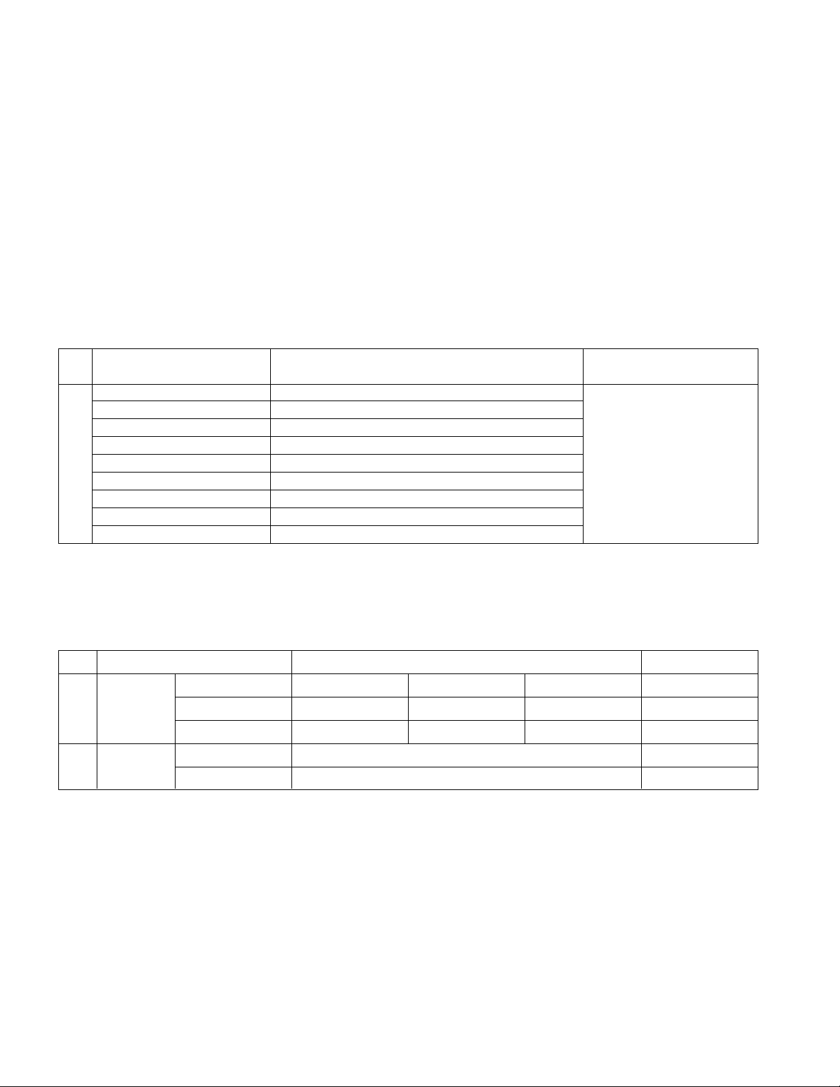
- Remove screws attached to stand by coin or (-) driver.
- Disassembly Stand from Set.
- Remove the battery.
- Disassembly Back cover after press the battery as pull the
edge of Back cover by hand as the picture.
- Remove Speaker's screws of both sides.
- Divide all AL TAPES and connectors from Metal Frame.
- Remove the POWER PCB screw.
7 8
-Remove the serews between metal frame and cabinet.
- Press latches on top-center and both side of cabinet and
then disassembly metal frame from the cabinet.
- Remove the screws on both side of metal frame,
disassembly metal frame and module.
AL Tape
AL Tape
Page 10
- 10 -
DISASSEMBLY
1 2
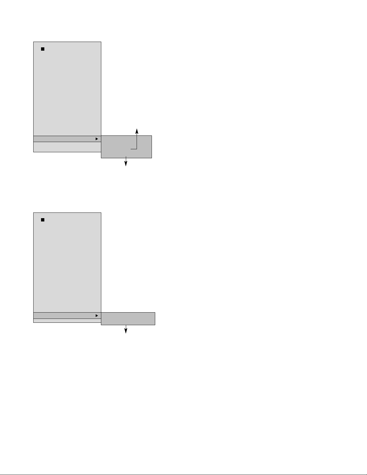
3 4
5 6
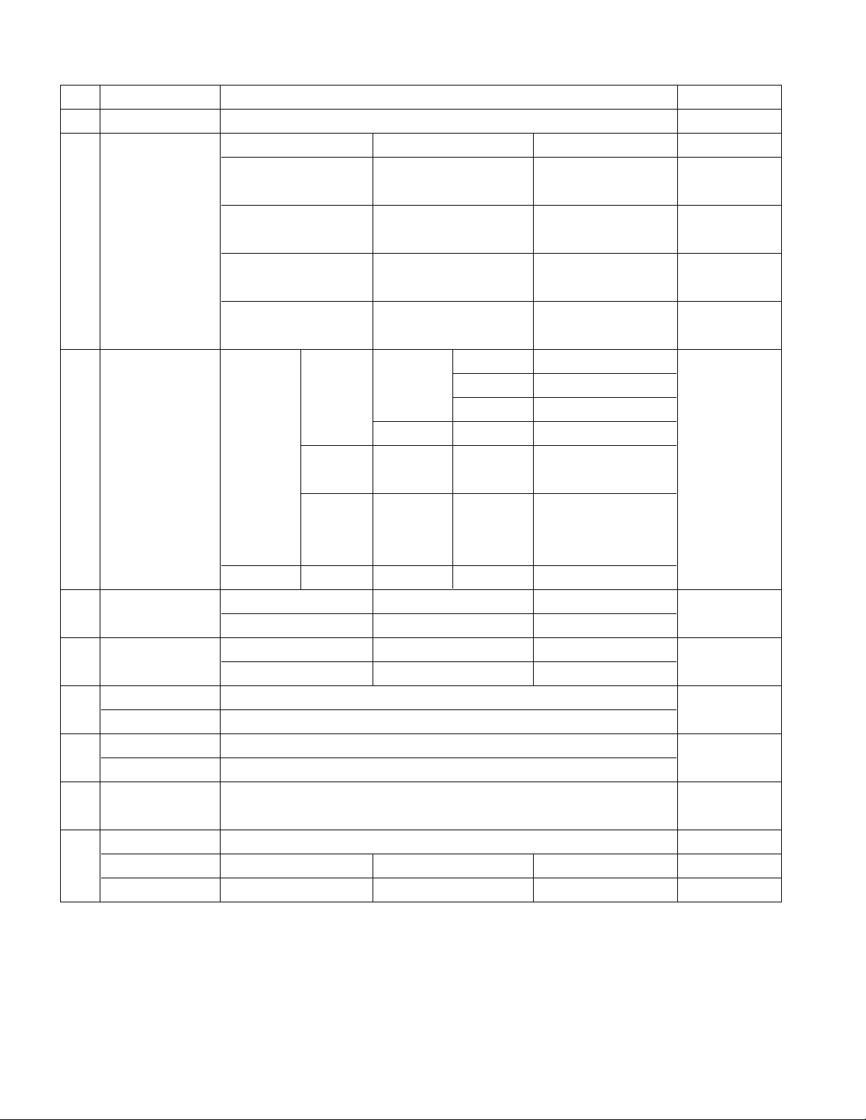
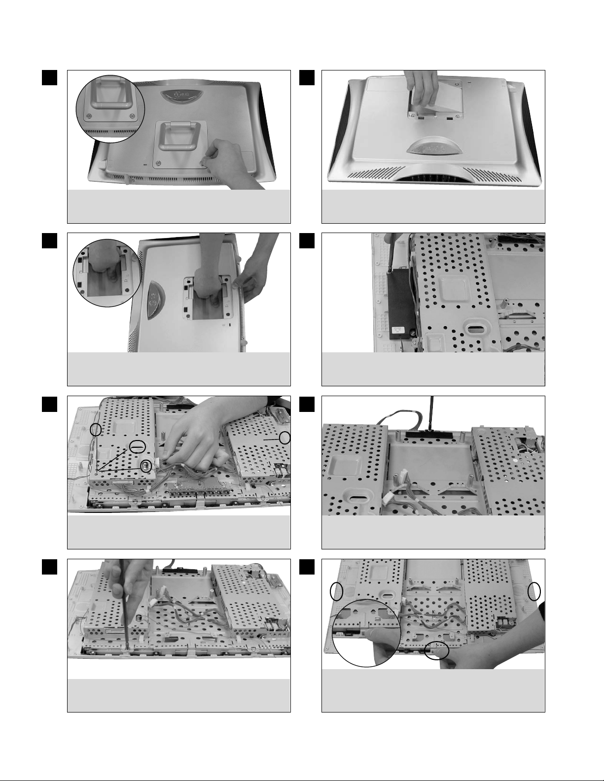
- Remove screws in stand.
- Push the cover to arrow direction.
- Lift cover. - Remove screws.
- Remove antenna and AL Tape as the picture. - Remove screws of Rear shield.
Al tape
7
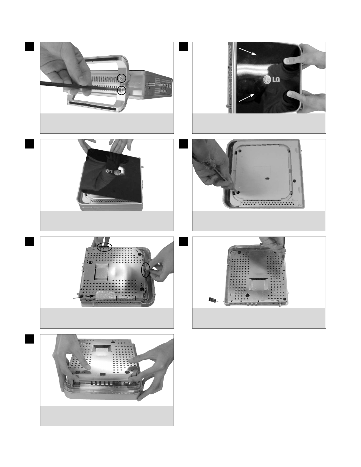
- Lift Rear shield as the picture.
Page 11
- 11 -
SERVICE TEST PROGRAM
1. Test Items
(MICOM : 1.3.0, ROMFS : 1.2 12/21 ENG), TX SSID : 80035E
(Rx Micom/Rx Flash/ Version Display), TX SSID display
- LED : Rx LED Operation Test
- Volume : Speaker Operation Test/Headphone Operation
Test(for headphone connection)
-
Brightness/Contrast : Rx SVC Mode Brightness/Contrast control
- Button : Rx Key Control Operation Test
- Remocon : Remocon Operation Test
- Battery : Battery information display
-
RX Longrun : Audio(Continuous Tone)/ Video(straight Color Bar)
- RX Factory Default : RX Flash Data Initialization: Volume,
Brightness
- Initialize SSID : Initialization of TX SSID connected with RX
- TX : Tx SSID Display/VCTI,Tx Flash Version Display Long
Run/Tx VCTI Data Initialization
- S/W Upgrade : Execute Rx Flash Update through AP(Access
Point)
- Canadian VCHIP : Default(No)
- Dot Defect : Full Black/White Pattern to check Dot Defect of the
LCD module
2. SSID input screen
* Screen appearing where SSID is not saved
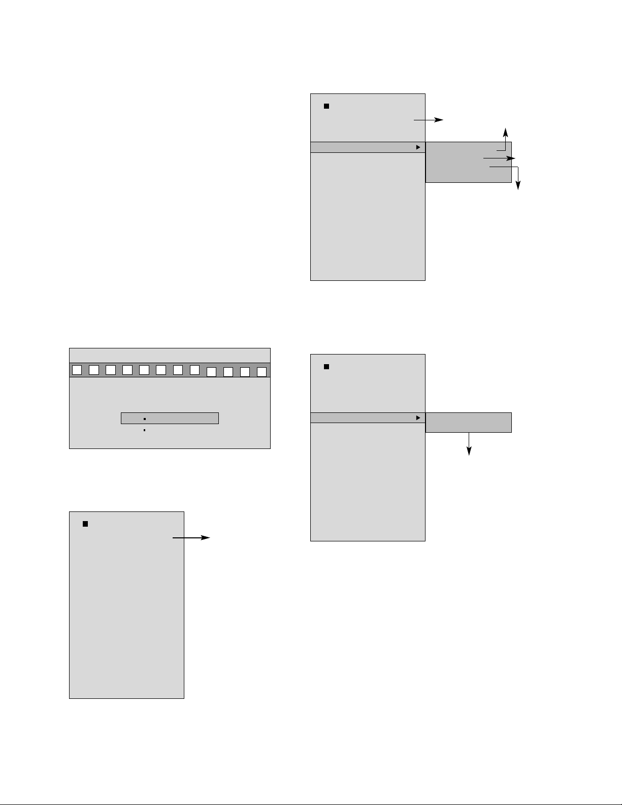
(1) Test initial screen
- Method to enter into the test screen
: Click the IN-START button of the Adjust Remocon (P/N:105-
201M) in the RX Power ON status(operable 10 seconds after On).
=> Click the Enter button of the REMOCON in order to select
detailed menu
(2) LED Test
- LED Operation Test of Rx
=> Click the Exit button of the REMOCON to return to the
previous initialization menu
(3) VOLUME Test
- Speaker Operation Test
=> Click the Exit button of the REMOCON to return to the
previous initialization menu
Press 'Select' to confirm, 'Exit' to retry
LWTV_8002FE
LWTV_8002EA
Test Items
(MICOM : 1.3.0, ROMFS :
1.2 12/21 ENG), TX SSID :
80035E
* LED
* Volume
* Brightness/Contrast
* Button
* Remocon
* Battery
* RX Longrun
* RX Factory Default
* Initialize SSID
* TX
* S/W Upgrade
* Canadian VCHIP :
* Dot Defect
Version
(Micom/CPU)
Test Items
(MICOM : 1.3.0, ROMFS :
1.2 12/21 ENG), TX SSID :
80035E
* LED
* Volume
* Brightness/Contrast
* Button
* Remocon
* Battery
* RX Longrun
* RX Factory Default
* Initialize SSID
* TX
* S/W Upgrade
* Canadian VCHIP :
* Dot Defect
Version
(Micom/CPU)
Blinking in blue color
Blinking in
Green color
Blinking in Yellow/Green color
Check LEDs are blinking
- Power LED (Blue)
- W-LAN LED (Green)
- Battery LED (Yellow/Green)
Volume is played in the level of 80 values.
Volume Testing..
Current Vol : 80
Test Items
(MICOM : 1.3.0, ROMFS :
1.2 12/21 ENG), TX SSID :
80035E
* LED
* Volume
* Brightness/Contrast
* Button
* Remocon
* Battery
* RX Longrun
* RX Factory Default
* Initialize SSID
* TX
* S/W Upgrade
* Canadian VCHIP :
* Dot Defect
Page 12
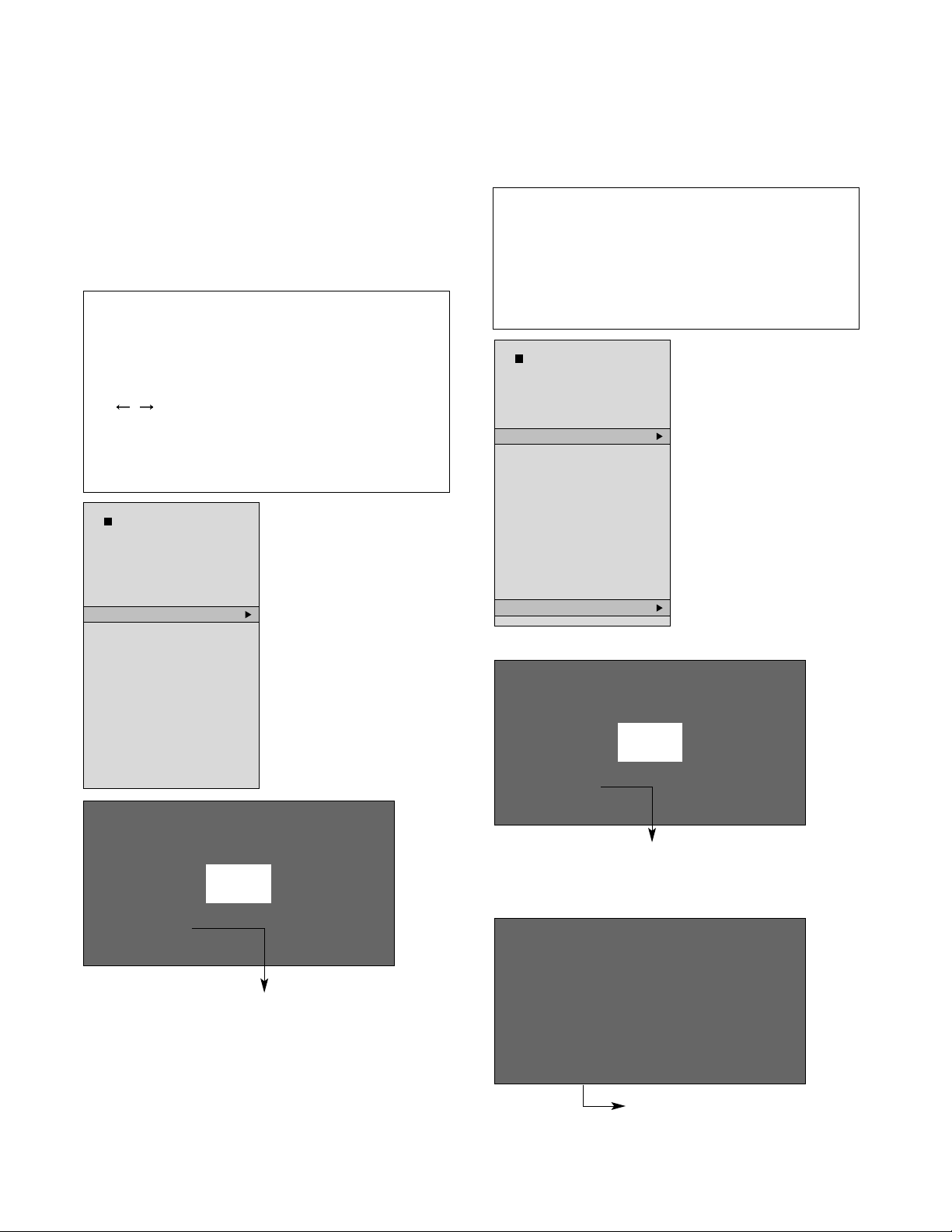
(4) Brightens/Contrast Adjust -1
- Adjust brightness value of the RX terminal
- Contrast has default of "138", not changed.(Number check
requied)
- Brightness Spec : 0.60~0.75 cd/m2
0.65 cd/m2 (Typ)
<-- Measuring value must be near 0.65 cd/m2 (Typ)
- Input signal : None
- Equipment required: Brightness meter (CA-110/210),
- Test conditions: Manufacturing A Line brightness measuring
location (darkroom)
- These data are not reset for the SSID,
- RX Factory Default Initialization.
=> Click the Exit button of the REMOCON to return to the
previous initialization menu
(5) Brightens/Contrast Adjust -2
- Adjust brightness value of the RX terminal when value less than
"-11" is required
- Input signal: None
- Equipment required: Brightness meter (CA-110/210)
- Test conditions: Manufacturing A Line
- Brightness measuring location (darkroom)
<Volume>
<Dot Defect>
- 12 -
1. Measure brightness in the Brightness/Contrast Mode after
aging. If brightness is insufficient, adjust it in following
method:
2. Adjustment method
- Move the cursor to Brightness by pressing arrow key(¡Ł/¡Ø)
- Change and adjust numbers by pressing the arrow key
( / ) so that brightness falls within Spec.
<-- Adjust measuring value near 0.65 cd/m2 (Typ).
- Save the Exit key for escape.
3. Brightness value must be " -10" or more.
(See following chapter for less than "-11")
1. After returning to the SVC mode by pressing the Exit Key
and selecting the DOT Defect Mode, measure brightness
value of the center part in the black screen by pressing the
numeric key "2".
2. Return the Brightness Adjustment Mode again, setup Spec
as below:
Brightness adjusting value +< 0.1~0.15> cd/m2 = Center
value in Dot Defect
Test Items
(MICOM : 1.3.0, ROMFS :
1.2 12/21 ENG), TX SSID :
80035E
* LED
* Volume
* Brightness/Contrast
* Button
* Remocon
* Battery
* RX Longrun
* RX Factory Default
* Initialize SSID
* TX
* S/W Upgrade
* Canadian VCHIP :
* Dot Defect
Contrast 138
Brightness 0
Contrast 138
Brightness 0
Initial Data
Select menu with the Up/Down button.
Change values with the Left/Right button.
Initial Data
Select menu with the Up/Down button
Change value with the Left/Right button
> Check Dot Defect
Press 1 for white, 2 for Black
Test Items
(MICOM : 1.3.0, ROMFS :
1.2 12/21 ENG), TX SSID :
80035E
* LED
* Volume
* Brightness/Contrast
* Button
* Remocon
* Battery
* RX Longrun
* RX Factory Default
* Initialize SSID
* TX
* S/W Upgrade
* Canadian VCHIP :
* Dot Defect
Page 13
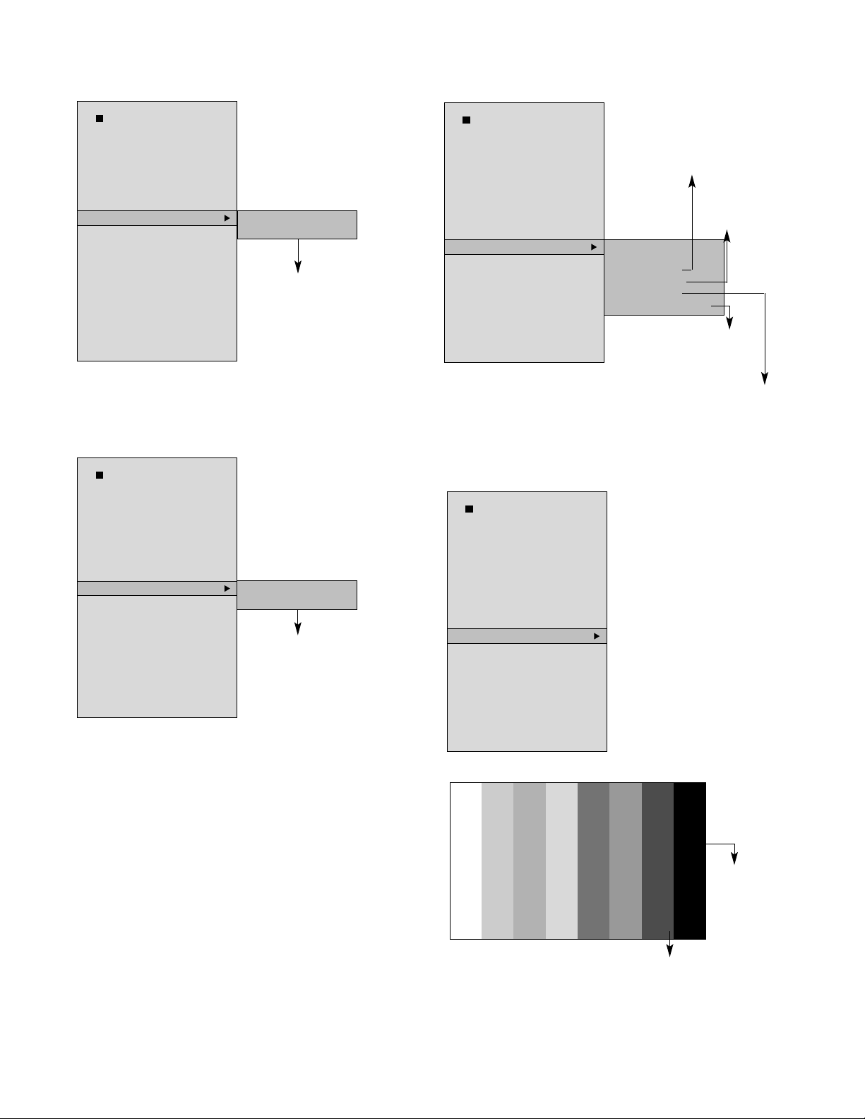
(6) Button Test
- Test whether there is key control operation of the RX
=> Click the Exit button of the REMOCON to return to the
previous initialization menu
(7) REMOCON Test
- Test whether there is key control operation of various keys
=> Click the Exit button of the REMOCON to return to the
previous initialization menu
(7) Battery Test
- Battery information display
=> Click the Exit button of the REMOCON to return to the
previous initialization menu
(8) RX Longrun
- Rx Long Run Mode
<Straight Color Bar Display on the whole of screen>
=> Click the Exit button of the REMOCON to return to the
previous initialization menu
- 13 -
Button name is displayed
whenever pressing the button.
(CH+, CH-, VOL+, VOL-,
MENU, SET, TV/AV)
> Press Button
CH +
Test Items
(MICOM : 1.3.0, ROMFS :
1.2 12/21 ENG), TX SSID :
80035E
* LED
* Volume
* Brightness/Contrast
* Button
* Remocon
* Battery
* RX Longrun
* RX Factory Default
* Initialize SSID
* TX
* S/W Upgrade
* Canadian VCHIP :
* Dot Defect
Remained battery capacity display (%)
Non-mounting of battery: N/A
Battery Error : ERROR
Battery temperature display
Continuous
Tone Play
Display whether there is connection f the adapter
Remained battery capacity display
Remained battery capacity and
voltage display
(Data may be different depending on
operation of the adapter.)
Test whether
there is operation
of the adapter.
> BATTERY Status
LIFE % : 50
AC : ON
TEMP : 20
VOLT : 12657mV
Test Items
(MICOM : 1.3.0, ROMFS :
1.2 12/21 ENG), TX SSID :
80035E
* LED
* Volume
* Brightness/Contrast
* Button
* Remocon
* Battery
* RX Longrun
* RX Factory Default
* Initialize SSID
* TX
* S/W Upgrade
* Canadian VCHIP :
* Dot Defect
Button name is displayed whenever
pressing the REMOCON Button.
(CH+, CH-, VOL+, VOL-, MENU, SET,
TV/AV, ...¶)
> Press Remocon Button
CH +
Test Items
(MICOM : 1.3.0, ROMFS :
1.2 12/21 ENG), TX SSID :
80035E
* LED
* Volume
* Brightness/Contrast
* Button
* Remocon
* Battery
* RX Longrun
* RX Factory Default
* Initialize SSID
* TX
* S/W Upgrade
* Canadian VCHIP :
* Dot Defect
Test Items
(MICOM : 1.3.0, ROMFS :
1.2 12/21 ENG), TX SSID :
80035E
* LED
* Volume
* Brightness/Contrast
* Button
* Remocon
* Battery
* RX Longrun
* RX Factory Default
* Initialize SSID
* TX
* S/W Upgrade
* Canadian VCHIP :
* Dot Defect
AC :CON.
Life % : 100
Page 14
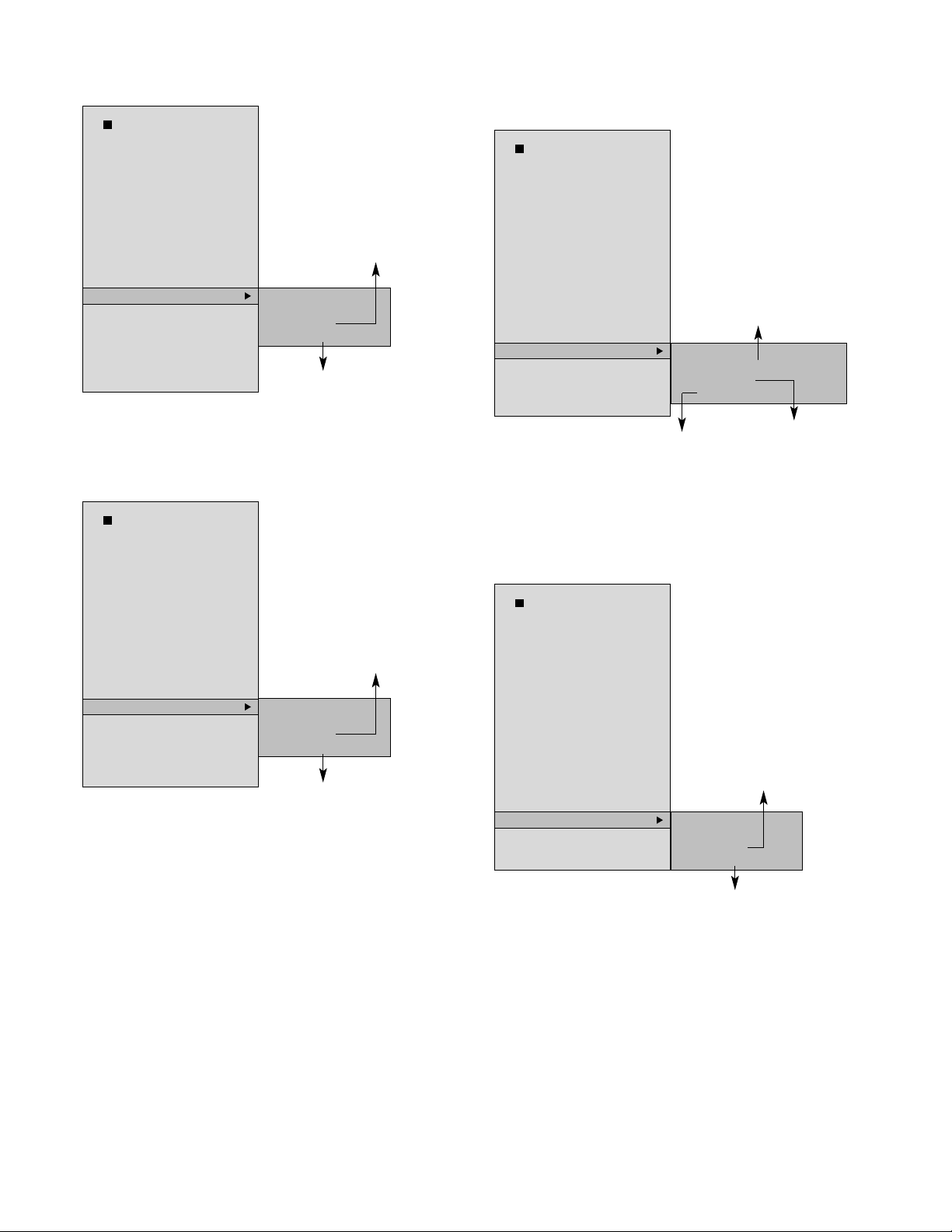
(9) RX Factory Default
- Rx Factory Mode (Initialization Mode)
=> Click the Exit button of the REMOCON to return to the
previous initialization menu
(10) Initialize SSID
- Delete the Tx SSID registered in the Rx.
=> Click the Exit button of the REMOCON to return to the
previous initialization menu
(11) TX
- TX Version display/Long Run Mode/TX Factory Default
(Initialization Mode)
=> Click the Exit button of the REMOCON to return to the
previous initialization menu
(12) S/W Upgrade
- Execute Rx Flash S/W Update
=> Click the Exit button of the REMOCON to return to the
previous initialization menu
- 14 -
Move the previous menu
Selected only when pressing the ENTER
button.
Move to previous mode after modification
of initialization
>FACTORY Default ?
YES
NO
Test Items
(MICOM : 1.3.0, ROMFS :
1.2 12/21 ENG), TX SSID :
80035E
* LED
* Volume
* Brightness/Contrast
* Button
* Remocon
* Battery
* RX Longrun
* RX Factory Default
* Initialize SSID
* TX
* S/W Upgrade
* Canadian VCHIP :
* Dot Defect
Selected only when pressing
the ENTER button.
Move to the previous mode
after TX Command Sending
Selected only when pressing
the ENTER button.
Move to previous mode after
modification of initialization
TX SSID / TX Version
> TX Testing
(LWTV_800XXX, K 1.8,RAMDISK :1.2)
-> TX Long Run
TX Factory Default
Test Items
(MICOM : 1.3.0, ROMFS :
1.2 12/21 ENG), TX SSID :
80035E
* LED
* Volume
* Brightness/Contrast
* Button
* Remocon
* Battery
* RX Longrun
* RX Factory Default
* Initialize SSID
* TX
* S/W Upgrade
* Canadian VCHIP :
* Dot Defect
Move the previous menu
Selected only when pressing the ENTER
button.
Move to previous mode after modification
of initialization
> SSID Initialize ?
YES
NO
Test Items
(MICOM : 1.3.0, ROMFS :
1.2 12/21 ENG), TX SSID :
80035E
* LED
* Volume
* Brightness/Contrast
* Button
* Remocon
* Battery
* RX Longrun
* RX Factory Default
* Initialize SSID
* TX
* S/W Upgrade
* Canadian VCHIP :
* Dot Defect
Move the previous menu
Selected only when pressing the ENTER
button.
Move to previous mode after modification
of initialization
> S/W Upgrade ?
YES
NO
Test Items
(MICOM : 1.3.0, ROMFS :
1.2 12/21 ENG), TX SSID :
80035E
* LED
* Volume
* Brightness/Contrast
* Button
* Remocon
* Battery
* RX Longrun
* RX Factory Default
* Initialize SSID
* TX
* S/W Upgrade
* Canadian VCHIP :
* Dot Defect
Page 15
(13) Canadian VCHIP
- Canadian VCHIP Yes/No
=> Click the Exit button of the REMOCON to return to the
previous initialization menu
(14) Dot Defect
- Inspect Dot Defect of LCD Module
=> Click the Exit button of the REMOCON to return to the
previous initialization menu
3. RX/TX Release Mode Initialization
- Release mode initialization
: TX terminal: VCTI EEPROM initialization
:
RX terminal : Initialization of User Flash Data (Volume/Brightness)
except for SSID
- Initialization method
: In use of Test Program
- Select "RX Factory Default" and "TX Factory Default" menu of
the Test Item menu.
4. Complete charging/discharging of
battery and Aging Test
- Battery shipment mode
: Release mode remained: 30% or more
:
Application method
- 100% charging in aging test
- Aging Test time
:
Battery 50% charging time: 2hours
- 15 -
Default : No
Select "Yes" when completing solution of
patent issued in relation with VCHIP
: To be published afterwards
> Enable Canadian VCHIP ?
YES
NO
Test Items
(MICOM : 1.3.0, ROMFS :
1.2 12/21 ENG), TX SSID :
80035E
* LED
* Volume
* Brightness/Contrast
* Button
* Remocon
* Battery
* RX Longrun
* RX Factory Default
* Initialize SSID
* TX
* S/W Upgrade
* Canadian VCHIP :
* Dot Defect
Remocon Button '1' : Full White Mode
Remocon Button '2' : Full Black Mode
> Check Dot Defect
Press 1 for White,2 for black
Test Items
(MICOM : 1.3.0, ROMFS :
1.2 12/21 ENG), TX SSID :
80035E
* LED
* Volume
* Brightness/Contrast
* Button
* Remocon
* Battery
* RX Longrun
* RX Factory Default
* Initialize SSID
* TX
* S/W Upgrade
* Canadian VCHIP :
* Dot Defect
Page 16
- 16 -
TROUBLESHOOTING
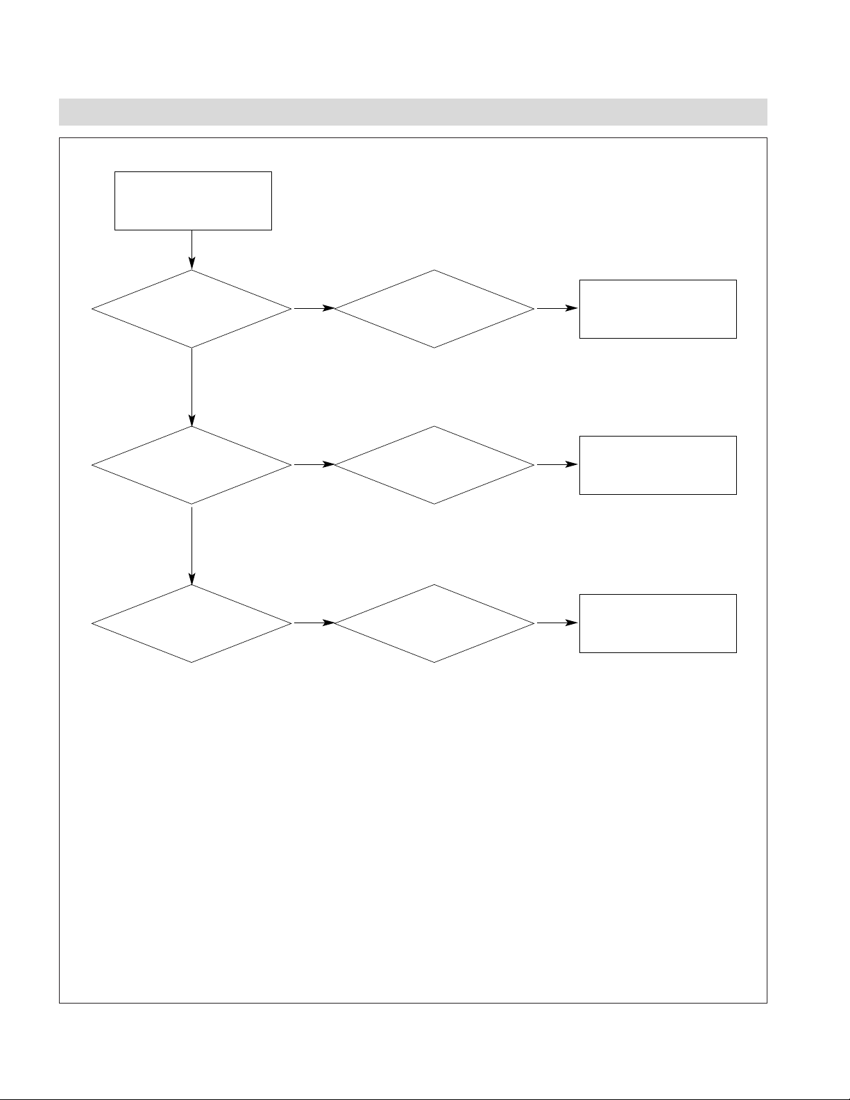
NO POWER
(POWER INDICATOR OFF)
Replace Power Adapter
Fail
1. OUT OF ORDER ON POWER (TX)
Fail
Replace or check soldering
of LCT1628 (U1006)
Fail Fail
Pass
Reprogram or Replace
VCT4973 (U603)
Fail Fail
Pass
Check PWRIN signal
on Main Board
Check 5V signal
VCC5.0V_VCT on Main
Board
Check
PWR_ON signal on
Main Board
Check
VCT4973(U603) on
Main Board
Check
LTC1628(U1006) on
Main Board
Check
16V or Connector(J1007)
on Power Adapter
Page 17
- 17 -
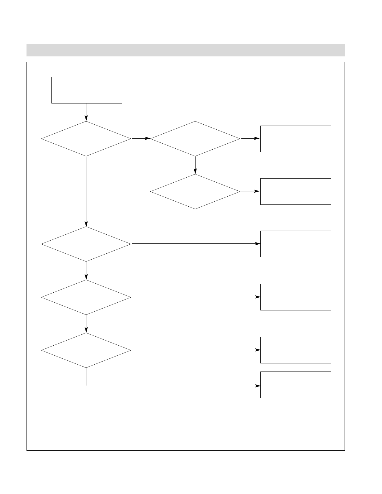
No Booting
Replace or check soldering
of LCT1628
Fail
2. OUT OF ORDER ON BOOTING (TX)
Fail
Replace or check soldering
of FAN1117(U1001)
Fail
Check Crystal circuit
Fail
Check bonding or part
around signal nSDCS0
Fail
Replace or reprogram of
Flash(U301)
Check Bonding of CPU
(U101)or CPU itself
Fail
Fail
Pass
Check
VCC3.3V signal on Main
Board
Check
6MHz Crystal (X1402)
Line signal on Main
Board
Check
nSDCS0 & SDCLK signal
on Main Board
Check Flash (U301)
If there is no signal on
nSDCS0 or SDCLK signal on Main Board
Check
LTC1628 (U1006) on
Main Board
Check VCC1.8V signal
Page 18
- 18 -
No MPEG Encoding or
Encoding Error
Replace or check soldering
of FAN1117(U1001)
Fail
3. OUT OF ORDER ON MPEG (TX)
Check 27MHz OSC Block
Fail
Pass
Check bonding of
CX23416 (U502) or
MPEG SDRAM (U501)
Fail
Pass
Check bonding of
MAIN_SCL_1 or
MAIN_SDA_1 circuit
Fail
Pass
Check
VCC1.25V signal on
Main Board
Check
MPEG_27M signal on
Main Board
Check
clock signal (135MHz) of
R509 side on
Main Board
Check
MAIN_SCL_1 or
MAIN_SDA_1 signal on
Main Board
Page 19

- 19 -
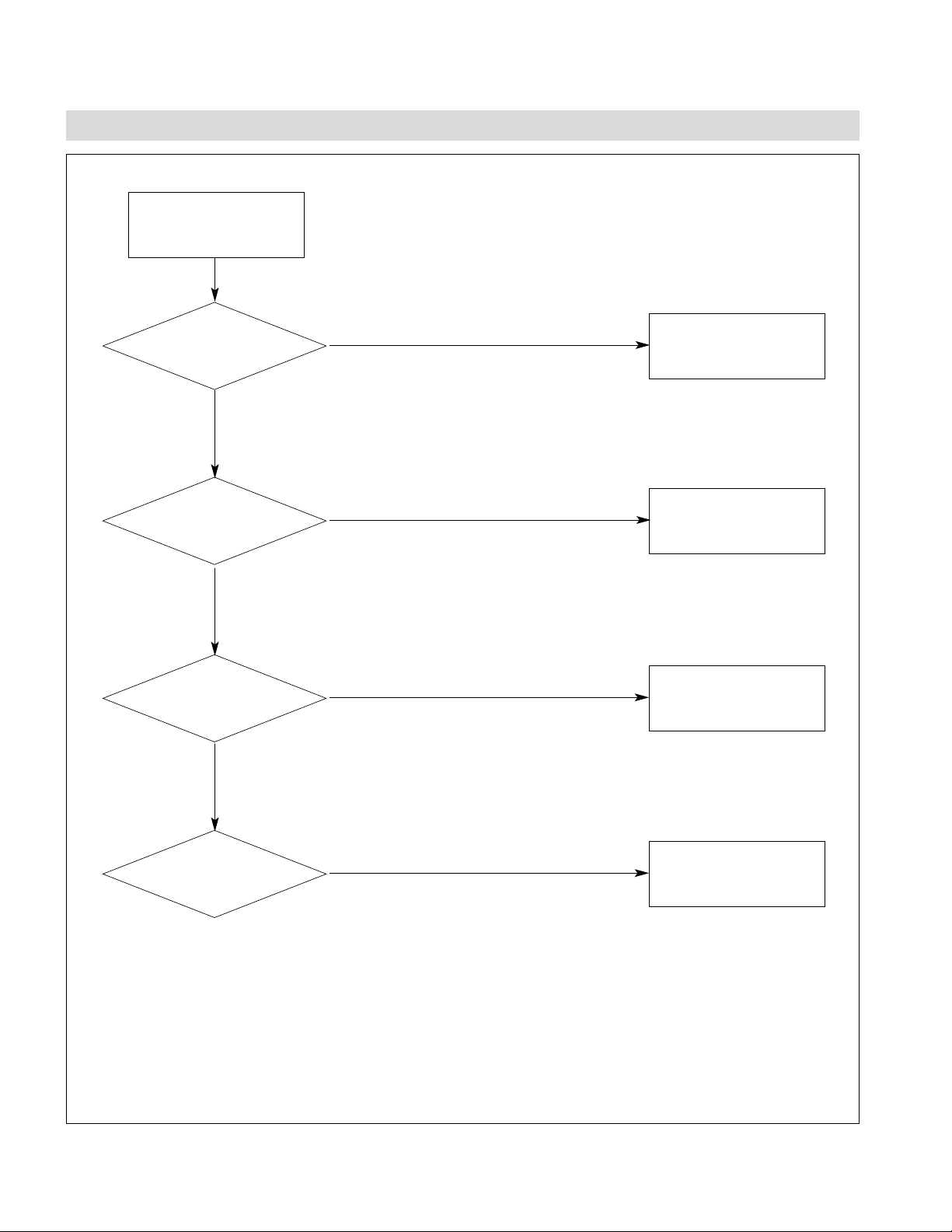
4. OUT OF ORDER ON TV (TX)
NO TV Signal or Noise
(POWER INDICATOR OK)
Reprogram or Replace
VCT4973(U603)
Fail Fail
Replace SAW Filter part
Fail Fail
Replace TR & Diode
Fail
Check IIC Line or
VCT4973(U603)
Fail
Pass
Check
VCC33V signal on
Main Board
IIC Line of TV Tuner on
Main Board
Check
11 pin of TV Tuner on
Main Board
Check
SAW Filter (U802) Block
on Main Board
Check
PWM_50KHZ signal on
Main Board
Check
TR & Diode on TV Tuner
Block
Page 20

- 20 -
No Power
Normal operation
Replace Adapter
No
Yes
Yes
5. POWER PART(POWER BOARD) (RX)
Replace Q205
No
Replace R206
No
Yes
Replace U301
No
Yes
Replace U301
No
Yes
Check DCIN
16V or not?
Check the
voltage of the pin no.
1 & 3 on Q205. 16V or
not ?
Check the
voltage of the pin No. 24
on U301.
16V or not ?
Check the
voltage of the pin No. 21
on U301.
5V or not ?
Check the
voltage of the pin No. 15
on U301.
5V or not?
Page 21

- 21 -
No power
Normal Operation
Check VCC3.3VSB and
U1202.
No
Yes
Yes
6. POWER PART(MAIN BOARD) (RX)
Check R1204, CB1204,
U1201 and U1202
No
Replace Q1901
No
Yes
Check J1201 and power
board.
No
Yes
Check U1905, U1904 and
Q1905
No
Yes
Check blue LEDs.
ON or not?
Check the
voltage of pin No. 1 on
Q1902.
3.3V or not ?
Check the
voltage of pin No.
5,6,7and 8 on Q1901.
3.3V or not ?
Check the
voltage of pin No. 4,5
and 6 on J1201.
5V or not ?
Check the
voltage of CP1905.
1.2V or not ?
Page 22

- 22 -
No video
Normal Operation
Replace Q206 on the
Power Board
No
Yes
Yes
7. VIDEO PART (RX)
Replace Cable and check
J302 on the power Board
No
Check Q1904
No
Yes
Check U1101 and U201
No
Yes
Check U1101 and U201
No
Yes
Yes
Check VCCINV
16V or not ?
Check
Inverter Cable
OK or not ?
Check VCCLCD
5V or not ?
Check the
clock of pin no. 31 on
U1101
65MHz or not ?
Check the
H/V sync signal of pin no.
27, 28 on U1101
OK or not?
Check J1101 and Cable
No
Check LVDS Cable
OK or not ?
Page 23

- 23 -
No audio
Normal Operation
Connect the cable on
J1301
No
Yes
Yes
8. AUDIO PART (RX)
Connect the Speaker Cable
No
Check FB1302
No
Yes
Check U1302, C1301,
C1302, R1320, R1321,
R1318, R1319
No
Yes
Check U201
No
Yes
Check
connection of Cable on
J1301 OK or not ?
Check
connection of Speaker
Cable OK or not ?
Check the
voltage of FB1302
5V or not ?
Check the
signal of pin no. 6, 8 on
U1301 OK or not ?
Check the
signal of pin no. 1,2,3,4
on U1302 OK or not ?
Page 24

- 24 -
Can’t battery-charging
Normal Operation
Correct the battery
connection
No
Yes
Yes
9. BETTERY PART (RX)
Check the Cable
connection
No
Check adapter
No
Yes
Check Microcontroller
No
Yes
Check U201
No
Yes
Yes
Check the battery
connection
OK or not ?
Check
connection of the cable
between J201 on power
board and J1901 on
main board
OK or not ?
Check
voltage of pin no.
1 on U201 on power
board 16V or not ?
Check
voltage of pin no. 14 on
U201 1.2V or not ?
Check
voltage of pin no. 4 on
U201 4V or not ?
Check Q202, Q203
No
Check
voltage of pin no. 1 on
J202 12.6V or not ?
Page 25

- 25 -
BLOCK DIAGRAM (RX)
Page 26

BLOCK DIAGRAM DESCRIPTION (RX)
- 26 -
1. The Media Processor(EM8620L)
The media processor which is used in this product is the EM8620L of Sigma Designs. The EM8620L consists of CPU and
decoder. The CPU is a ARM7TDMI core and the decoder covers MPEG-2, MPEG-4, WMV9 and Divx. Also the EM8620L
has many built-in functions that they are PCI/Peripheral BUS, Digital Audio Processor, Video/Graphic processor and DoubleData Rate SDRAM Controller etc.
In this product the PCI Bus controls a wireless LAN card of MiniPCI type and Digital Audio Processor controls a DAC device
externally that it converts digital audio data into analogue audio signal. Also the Graphics controller sends 24 bit digital RGB
data to a LVDS device. The LVDS device interfaces with LCD module.
2. Wireless LAN
The Wireless LAN Card which is used in the product is manufactured by LG Innotek. The card satisfied with IEEE802.11 b/g
standard. The product name is LVMM-3001A.
The maximum bandwidth of LVMM-3001A is 54Mbps and its operation frequency is about 2.4GHz.
3. DDR SDRAM
The receiver has total 64Mbytes double-data rate SDRAM. 16Mbytes of 64Mbytes is the space for the decoder and the rest
is for applications. The speed of the SDRAM is 166MHz. We use ferrite beads and capacitors on the clock lines to reduce
EMI. SDRAM devices use 2.5V and 1.2V for operational voltages.
4. Clock of the Media Processor(EM8620L)
Internal PLL circuit of the EM8620L generates three clock signals using 27MHz crystal oscillator input. One is 166MHz clock
of the SDRAM input, another is 65MHz clock of the Digital RGB part, and the third is 24.576MHz of Audio part.
5. UART(RS-232)
EM8620L has two on-chip UARTs. The UART0 is used for system debugging, and the UART1 is used to communicate with
the microcontroller. The Information of key button control, battery, and power management that the microcontroller gets, is
transported to the UART1 interface of EM8620L
6. Audio Interface
EM8620L has a built-in digital audio processor that it is able to decode MP3 files or WMA files. The decoded data is
transported into WM8728, DAC Chip and it converts digital input data to analog signals. These signals are transmitted to
speaker via TPA6011A4, Audio Amplifier.
7. Flash Memory
RM-15LW10 has two kinds of program memory. One is serial flash memory; the other is parallel flash memory. In serial flash
memory, it is stored the program that initializes the CPU and peripherals before loading OS to main memory, and this
program is called 'bootloader'. The OS to control the system is stored in the parallel flash memory. Bootloader stored in
serial flash reads the OS image from the parallel flash and writes the image to the DRAM and then, launches the OS loaded
into DRAM.
8. Digital RGB
EM8620L displays the video in LCD panel by transmitting the digital RGB signal to external LVDS chip. The digital RGB
signals that consist of 24-bit color, horizontal sync, vertical sync, and 65MHz clock are transmitted to LVDS chip. The signals
are converted to Low Voltage Differential Signal and sent to the LCD panel.
9. Microcontroller
An 8051-compatible 8-bit microcontroller, CS8954 controls battery management, key button, remote control, and power
management in this system. It controls battery-charging and discharging status, and manages audio volume, channel, and
remote control signal. It also plays a role of system power manager to control power supply effectively.
Page 27

- 27 -
S-Video
Jack
SC, SY
SC_OUT1,
SY_OUT1
CVBS_IN
V_OUT1 MNT_CVBS_OUT1
RED,
GRN,
BLU
ITU_T
R.656
VIDIN0~7
ARV_1,
ALV_1
R_OUT1,
L_OUT1
MNT_SC_OUT1,
MNT_SY_OUT1
S-Video
Jack
OP
Amp
OP
Amp
VCT4973 CX23416
MST
9883
Array
Resistor
RCA
Video
Input
RCA
Audio
Input
RCA
Video
Output
RCA
Audio
Output
WIRELESS TV TX BOARD BLOCK DIAGRAM(TX-A/V)
Page 28

- 28 -
P_AD[0..31]
PCI Rev 2.1
compliant
P_AD[0..31]
MPEG
Encoder
CX23416
Wireless LAN
PCI
Controller
RS232
Driver/
Receiver
UART0
Controller
Video ADC
MST9883C
VIDIN[0..7]
RGB(3)
SDA_1
SCL_1
Audio ADC
PCM1802
OSC
12.288MHz
SDA_1
SCL_1
PCM_SCLKI
PCM_DOUT
SPK_LA
SPK_RA
AUDIO_OSC_CLK
PCM_LRCK
UART
Controller
TV_Tuner
IF
S3C2800 VCT4973
Power Tact
Switch
Power
On/Off
Block
Flash
Memory
4MBytes
DRAM
32MBytes
S-Video
Output
S-Video
Input
RCA
Audio/Video
Output
RCA
Audio/Video
Input
DC-
Adapter
Jack
PWRIN
DSUB9
Port
SDA_1
SCL_1
POWER_
TACT
PWR_
ON
UART1
Controller
UART1
Controller
Video
Memory
8Mbytes
WIRELESS TV TX BOARD BLOCK DIAGRAM (TX)
Page 29

DESCRIPTION OF BLOCK DIAGRAM (Wireless TV TX)
- 29 -
1. CPU & Memory Block
S3C2800 Samsung CPU is used for the main processor. S3C2800 offers embedded PCI Host Bridge. Input frequency is
6MHz and maximum output frequency is 200MHz. PCI interface supports 32bit data bus at 33MHz/66MHz and wireless TV
TX system is using 33MHz system. Wireless TV TX system supports 4Mbytes Flash Memory and 32Mbytes SDRAM
Memory. Flash Memory is MX29LV320ABTC-90 and SDRAM Memory is composed of two 16 Mbytes SDRAM
K4S281632F-TC75.
2. MPEG Encoder
MPEG II A/V Encoding system is used by Conexant CX23416-12(U502). It contains memory controller and interfaces
directly with HY57V643220DT-7(U501). CX23416 is interfaced with CPU by PCI interface. Input Analog signal is converted
to digital signal and Mpeg encoded by CX23416 and transmitted to wireless TV RX system by wireless interface. It supports
ITU-T 656 format and input frequency is 27MHz.
3. Video/Audio Processor & Micom
VCT4973(U603) contains several functions which is essential for wireless TV TX system. VCT4973(Micronas inc) contains
Video processor, Audio processor, micom function, V-Chip function, I2C interface. Input crystal oscillator frequency is
20.25MHz. Video/Audio signal form external AV interface is transferred to A/D Converter. Power Management function is
performed by micom function. When Adapter is connected with wireless TV TX system, Standby power 1.8V, 3.3V is applied
to the system and maintains Standby status and if you push the power switch, Normal power is applied to the system.
4. Wireless LAN
Wireless LAN card is LG INNOTEK inc Wireless LAN card(Model:LWMM-3002A). Wireless LAN interface is interfaced by
MiniPCI Type IIIA interface which is Soft MAC. Main chip is Conexant Inc. wireless LAN chip. Wireless LAN card is
convertible with 802.11b(max 11Mbps) & 802.11g(max 54Mbps).
5. TV Tuner
TV Tuner is LG INNOTEK Inc. TAEW-G351P. SAW Filter is not included to the tuner and internal booster is included to the
tuner. The tuner adopts external 2 Antenna Connectors. One is for input TV signal and the other is output TV signal. TV
tuner is controlled by VCT4973 through IIC interface. SAW Filter is EPOS Inc. X6966. X6966(U802) uses 38.9MHz IF
frequency. IF signal from TV Tuner is passing through SAW Filter and transferred to VCT4973. TV Tuner’s 33V is made by
Transistor, Diode circuit and PWM signal. VCT4973 is sending PWM signal to 33V circuit.
6. AD Converter
This circuit uses Mstar Semiconductor Inc. MST9883(U702) as Video ADC. In case of Audio ADC, TI Inc. PCM1802 is
used. Video signal from VCT4973 is transformed to ITU-T R.656 format and transferred to MPEG Encoder. Audio signal
from VCT4973 is transferred to Audio ADC PCM1802(U701) and passed to MPEG Encoder. PCM1802 gets input frequency
12.28MHz. MST9883 and PCM1802 has IIC interface and VCT4973 controls them through IIC interface.
7. Clock distribution & Spread Spectrum
Clock system is mainly composed of CDCVF2505 and CY25812. Clock system offers 33MHz frequency to main CPU PCI
master/slave system, MPEG Encoder, and Wireless LAN(MiniPCI circuit). Input Crystal frequency is 16.6MHz and this
frequency is applied to CDCVF2505 and it outputs 33MHz. 33MHz can interfere with other signals and be EMI main source
signal. Cypress Inc. CY25812 is used to spread frequency around 33MHz and reduces EMI value to adequate level. .
8. DC-DC Converter
DC-DC Converter is composed of LTC1628 and regulator circuits. 110V/220V 60Hz DC power adapter output signal is 16V
and wireless TV TX system input power is 16 V. 16V input power is converted to 8V by regulator (78M08), and to standby
5V, 3.3V by regulator (LTC1628) and Normal 5V, 3.3V is controlled by the signal ON/OFF from VCT4973. From standby
3.3V, standby and Normal 1.8V, 1.25V is made by regulator (FAN1117, REG1117). 1.8V power is used by VCT4973, and
main processor S3C2800. 1.25V is used by MPEG Encoder.
Also, 5V, 3.3V Power control is done by FET circuit controlled by micom in A/V multi processor VCT4973. Once external
Power TACT switch signal is detected by micom in VCT4973, micom remembers its signal status as toggle method. Push
the button and power is on. If you push again, power is off. This way power is controlled. If DC adapter is connected,
Standby power(5V, 3.3V, 1.8V) for TV tuner and video/audio system is maintained without regard to power switch push
status.
In case of TV Tuner(TAEW series). 5V and 33V is needed., PWM signal from VCT4973 is amplified by transistor and
rectified by diode. This way 33V is made. This 33V is also standby power. In Standby status, TV Tuner input/output is
operating.
Page 30

- 30 -
WIRING DIAGRAM
No. Part No.
1
2
3
4
5
6
7
8
9
10
11
12
Wiring Part List
5010TZZ001E
5010TZZ001F
6631T20010A
6631T20034G
6631T20010C
6401TZZ035C
6631T20034F
6631T20033H
6631T20015D
6631T20015A
6631T20020E
6631T11020T
2
3
ETC
6
7
12
SPEAKERSPEAKER
MAIN PCBPOWER PCBINVERTER
9 8
4
5
ETC
1
ETC
10
ASS'Y
11
ETC
Page 31

- 31 -
EXPLODED VIEW
010
020
110
060
030
200
210
180
190
070
040
220
100
120
130
050
080
090
120
140
150
160
170
Page 32

- 32 -
EXPLODED VIEW PARTS LIST
No.
PART NO.
DESCRIPTION
3091TKL134B CABINET ASSEMBLY, 15LW10 BRAND L107 SILVER/BLACK(REV)
6304FLP133B
LCD(LIQUID CRYSTAL DISPLAY), LC150X02-A4 LG PHILPS TFT COLOR COST COMPENSATION
or 6304FLP133A
LCD(LIQUID CRYSTAL DISPLAY), LC150X02-A4 LG PHILPS TFT COLOR TN,XGA,450NITS,8BITS LVDS
3809TKL092A BACK COVER ASSEMBLY, 15LW10 L087 SILVER/BLACK(EXPORT)
3043TKK217B TILT SWIVEL ASSEMBLY, 15LW10 VESA STAND(SILVER WITH THUMB SCREW)
3043TKK211A TILT SWIVEL ASSEMBLY, 15LW10 . STANS ASSY
6401TZZ035C SPEAKER ASSEMBLY, WIRELESS, 2W,4OHM,5PIN, L80 R800
4951TKS181B METAL ASSEMBLY, FRAME 15LW10(REV)
6871TMTA17A
PWB(PCB) ASSEMBLY,MAIN, 15LW1R-UA ANUSLAX BRAND ML - 042A RX MAIN TOTAL
5010TZZ001E ANTENNA, KOSAN DIPOLE 50 OHM,L190MM
5010TZZ001F ANTENNA, KOSAN DIPOLE 50 OHM,L380MM
6871TST764A PWB(PCB) ASSEMBLY,SUB, 15LW10 ETC TOTAL BRAND RX
4810TKK294A BRACKET, 15LW10 HOLDER ANT(ABS, BK)
6871TST764A PWB(PCB) ASSEMBLY,SUB, 15LW10 ETC TOTAL BRAND RX
6871TST764A PWB(PCB) ASSEMBLY,SUB, 15LW10 ETC TOTAL BRAND RX
6871TST764A PWB(PCB) ASSEMBLY,SUB, 15LW10 ETC TOTAL BRAND RX
6633TZA019A INVERTER ASSEMBLY, FRONTEK FIF1542-51A 15 WIRELESS
6871TPT297B PWB(PCB) ASSEMBLY,POWER, 15LW10 POWER TOTAL BRAND RX POWER
4814TKK291A SHIELD, INVERTER CAP
4814TKK291B SHIELD, INVERTER CAP(BOTTOM)
6910C00027A
BATTERY,LITHIUM, LG-WTB01-02 SUNGNAM ELECTRONIC CO. 11.1V 4400mAh 3S2P, UL, LG-WTB01-02
4810TKK278A BRACKET, 15LW10 HOLDER POWER PCB
6718M000006
LANCARD, MINI PCI, LWMM-3001B LG IT INTERFACE STANDARD IEEE802, 11G 54M RX FOR WIRELESS TV(AMERICA).
010
020
030
040
050
060
070
080
090
100
110
120
130
140
150
160
170
180
190
200
210
220
Page 33

- 33 -
EXPLODED VIEW
010
020
030
040
050
060
070
080
Page 34

- 34 -
EXPLODED VIEW PARTS LIST
No.
PART NO.
DESCRIPTION
3313T15103A MAIN TOTAL ASSEMBLY, 15LW1R-UA BRAND ML-042A
3551TKK545A COVER ASSEMBLY, 15LW10 TOTAL . TOP ASSY(TX)
4815TKK043A SHIELD ASSEMBLY, TOP MAIIN(15LW10)
6871TMT787B PWB(PCB) ASSEMBLY,MAIN, 15LW10 TX BRAND ML- 042A TOTAL
4814TKK290A SHIELD, REAR .
3551TKK546A COVER ASSEMBLY, 15LW10 TOTAL . BOTTOM ASSY(TX)
3550TKK648B COVER, M15XX SIDE DECO_RIGHT
3551TKK547A COVER ASSEMBLY, 15LW10 TOTAL . STAND ASSY(TX)
010
020
030
040
050
060
070
080
Page 35

- 35 -
DATE: 2005. 01. 10.
*S *AL LOC. NO. PART NO. DESCRIPTION / SPECIFICATION
CP802 DCH7106F621 10UF 16V M 3528MM TP(-)
CP803 DCH7106F621 10UF 16V M 3528MM TP(-)
CP902 DCH7106F621 10UF 16V M 3528MM TP(-)
CP903 DCH7106F621 10UF 16V M 3528MM TP(-)
CP904 DCH7106F621 10UF 16V M 3528MM TP(-)
CP101 DCH7106F621 10UF 16V M 3528MM TP(-)
CP1011 0CH7475F621 4.7UF 16V M 3528 TP(-)
CP102 DCH7106F621 10UF 16V M 3528MM TP(-)
CP103 DCH7106F621 10UF 16V M 3528MM TP(-)
CP104 DCH7106F621 10UF 16V M 3528MM TP(-)
CP105 DCH7106F621 10UF 16V M 3528MM TP(-)
CP106 DCH7106F621 10UF 16V M 3528MM TP(-)
CP107 DCH7106F621 10UF 16V M 3528MM TP(-)
CP108 DCH7106F621 10UF 16V M 3528MM TP(-)
CP109 DCH7106F621 10UF 16V M 3528MM TP(-)
CP110 DCH7106F621 10UF 16V M 3528MM TP(-)
CP111 DCH7106F621 10UF 16V M 3528MM TP(-)
CP112 DCH7106F621 10UF 16V M 3528MM TP(-)
CP113 DCH7106F621 10UF 16V M 3528MM TP(-)
CP114 DCH7106F621 10UF 16V M 3528MM TP(-)
CP201 DCH7106F621 10UF 16V M 3528MM TP(-)
CP202 DCH7106F621 10UF 16V M 3528MM TP(-)
CP301 DCH7106F621 10UF 16V M 3528MM TP(-)
CP401 0CH7475F621 4.7UF 16V M 3528 TP(-)
CP402 0CH7475F621 4.7UF 16V M 3528 TP(-)
CP403 0CH7475F621 4.7UF 16V M 3528 TP(-)
CP501 0CH7475F621 4.7UF 16V M 3528 TP(-)
CP1001 DCH7106F621 10UF 16V M 3528MM TP(-)
CP1002 DCH7106F621 10UF 16V M 3528MM TP(-)
CP1003 DCH7106F621 10UF 16V M 3528MM TP(-)
CP1004 DCH7106F621 10UF 16V M 3528MM TP(-)
CP801 DCH7106F621 10UF 16V M 3528MM TP(-)
CP901 DCH7106F621 10UF 16V M 3528MM TP(-)
CP905 DCH7106F621 10UF 16V M 3528MM TP(-)
CP906 DCH7106F621 10UF 16V M 3528MM TP(-)
CB1001 0CZZTCT006C C3225Y5V1E106Z TDK 25V 10UF
CB1002 0CZZTCT006C C3225Y5V1E106Z TDK 25V 10UF
CB1003 0CZZTCT006C C3225Y5V1E106Z TDK 25V 10UF
CB1004 0CZZTCT006C C3225Y5V1E106Z TDK 25V 10UF
CB1008 0CZZTCT006C C3225Y5V1E106Z TDK 25V 10UF
CB1014 0CZZTCT006C C3225Y5V1E106Z TDK 25V 10UF
CP1008 0CZZTST002B EEFUD0G181R MATSUSHITA 4V 18
CP1014 0CZZTST002D EEFUD0J151R MATSUSHITA 6.3V
CP607 0CZZTST002D EEFUD0J151R MATSUSHITA 6.3V
CP804 0CZZTST002D EEFUD0J151R MATSUSHITA 6.3V
CP806 0CZZTST002D EEFUD0J151R MATSUSHITA 6.3V
CB1906 0CZZTCT006C C3225Y5V1E106Z TDK 25V 10UF
CP1904 0CZZTST002C EEFCD0J470R MATSUSHITA 6.3V
CP1905 0CZZTST002B EEFUD0G181R MATSUSHITA 4V 18
CP1906 0CZZTST002D EEFUD0J151R MATSUSHITA 6.3V
C1004 0CK104CK56A 0.1UF 1608 50V 10% R/TP X7R
C1006 0CK105DK94A "1UF 2012 50V 80%,-20% R/TP F"
C601 0CK104CK56A 0.1UF 1608 50V 10% R/TP X7R
C602 0CK104CK56A 0.1UF 1608 50V 10% R/TP X7R
DATE: 2005. 01. 10.
*S *AL LOC. NO. PART NO. DESCRIPTION / SPECIFICATION
C603 0CK104CK56A 0.1UF 1608 50V 10% R/TP X7R
C604 0CK822CK56A 8200PF 1608 50V 10% X7R R/TP
C605 0CK822CK56A 8200PF 1608 50V 10% X7R R/TP
C607 0CK334CF94A "0.33UF 1608 16V 80%,-20% F(Y"
C608 0CK334CF94A "0.33UF 1608 16V 80%,-20% F(Y"
C620 0CK104CK56A 0.1UF 1608 50V 10% R/TP X7R
C705 0CK393CK56A 39000PF 1608 50V 10% R/TP X7
C706 0CK392CK56A 3900PF 1608 50V 10% R/TP X7R
CB103 0CK104CK56A 0.1UF 1608 50V 10% R/TP X7R
CB104 0CK104CK56A 0.1UF 1608 50V 10% R/TP X7R
CB105 0CK104CK56A 0.1UF 1608 50V 10% R/TP X7R
CB106 0CK104CK56A 0.1UF 1608 50V 10% R/TP X7R
CB107 0CK104CK56A 0.1UF 1608 50V 10% R/TP X7R
CB108 0CK104CK56A 0.1UF 1608 50V 10% R/TP X7R
CB109 0CK104CK56A 0.1UF 1608 50V 10% R/TP X7R
CB110 0CK104CK56A 0.1UF 1608 50V 10% R/TP X7R
CB111 0CK104CK56A 0.1UF 1608 50V 10% R/TP X7R
CB112 0CK104CK56A 0.1UF 1608 50V 10% R/TP X7R
CB113 0CK104CK56A 0.1UF 1608 50V 10% R/TP X7R
CB114 0CK104CK56A 0.1UF 1608 50V 10% R/TP X7R
CB1301 0CK104CK56A 0.1UF 1608 50V 10% R/TP X7R
CB1302 0CK104CK56A 0.1UF 1608 50V 10% R/TP X7R
CB1303 0CK104CK56A 0.1UF 1608 50V 10% R/TP X7R
CB1304 0CK104CK56A 0.1UF 1608 50V 10% R/TP X7R
CB1305 0CK104CK56A 0.1UF 1608 50V 10% R/TP X7R
CB1306 0CK104CK56A 0.1UF 1608 50V 10% R/TP X7R
CB1307 0CK104CK56A 0.1UF 1608 50V 10% R/TP X7R
CB1308 0CK104CK56A 0.1UF 1608 50V 10% R/TP X7R
CB1408 0CK104CK56A 0.1UF 1608 50V 10% R/TP X7R
CB212 0CK104CK56A 0.1UF 1608 50V 10% R/TP X7R
CB213 0CK104CK56A 0.1UF 1608 50V 10% R/TP X7R
CB401 0CK103CK51A 0.01UF 1608 50V 10% R/TP B(Y
CB402 0CK104CK56A 0.1UF 1608 50V 10% R/TP X7R
CB403 0CK103CK51A 0.01UF 1608 50V 10% R/TP B(Y
CB404 0CK104CK56A 0.1UF 1608 50V 10% R/TP X7R
CB405 0CK103CK51A 0.01UF 1608 50V 10% R/TP B(Y
CB406 0CK103CK51A 0.01UF 1608 50V 10% R/TP B(Y
CB407 0CK103CK51A 0.01UF 1608 50V 10% R/TP B(Y
CB408 0CK104CK56A 0.1UF 1608 50V 10% R/TP X7R
CB409 0CK103CK51A 0.01UF 1608 50V 10% R/TP B(Y
CB410 0CK103CK51A 0.01UF 1608 50V 10% R/TP B(Y
CB411 0CK103CK51A 0.01UF 1608 50V 10% R/TP B(Y
CB412 0CK104CK56A 0.1UF 1608 50V 10% R/TP X7R
CB413 0CK104CK56A 0.1UF 1608 50V 10% R/TP X7R
CB414 0CK104CK56A 0.1UF 1608 50V 10% R/TP X7R
CB415 0CK104CK56A 0.1UF 1608 50V 10% R/TP X7R
CB416 0CK104CK56A 0.1UF 1608 50V 10% R/TP X7R
CB417 0CK103CK51A 0.01UF 1608 50V 10% R/TP B(Y
CB419 0CK103CK51A 0.01UF 1608 50V 10% R/TP B(Y
CB421 0CK103CK51A 0.01UF 1608 50V 10% R/TP B(Y
CB501 0CK103CK51A 0.01UF 1608 50V 10% R/TP B(Y
CB502 0CK103CK51A 0.01UF 1608 50V 10% R/TP B(Y
CB503 0CK103CK51A 0.01UF 1608 50V 10% R/TP B(Y
CB504 0CK103CK51A 0.01UF 1608 50V 10% R/TP B(Y
REPLACEMENT PARTS LIST
MAIN BOARD
CAPACITOR
For Capacitor & Resistors, the
charactors at 2nd and 3rd digit in the
P/No. means as follows;
CC, CX, CK, CN, CH : Ceramic
CQ : Polyestor
CE : Electrolytic
CF : Fixed Film
RD : Carbon Film
RS : Metal Oxide Film
RN : Metal Film
RH : CHIP, Metal Glazed(Chip)
RR : Drawing
Page 36

- 36 -
DATE: 2005. 01. 10.
*S *AL LOC. NO. PART NO. DESCRIPTION / SPECIFICATION
CB505 0CK103CK51A 0.01UF 1608 50V 10% R/TP B(Y
CB506 0CK103CK51A 0.01UF 1608 50V 10% R/TP B(Y
CB507 0CK103CK51A 0.01UF 1608 50V 10% R/TP B(Y
CB508 0CK103CK51A 0.01UF 1608 50V 10% R/TP B(Y
CB509 0CK103CK51A 0.01UF 1608 50V 10% R/TP B(Y
CB602 0CK104CK56A 0.1UF 1608 50V 10% R/TP X7R
CB604 0CK104CK56A 0.1UF 1608 50V 10% R/TP X7R
CB607 0CK104CK56A 0.1UF 1608 50V 10% R/TP X7R
CB609 0CK104CK56A 0.1UF 1608 50V 10% R/TP X7R
CB610 0CK104CK56A 0.1UF 1608 50V 10% R/TP X7R
CB612 0CK104CK56A 0.1UF 1608 50V 10% R/TP X7R
CB613 0CK104CK56A 0.1UF 1608 50V 10% R/TP X7R
CB615 0CK104CK56A 0.1UF 1608 50V 10% R/TP X7R
CB617 0CK104CK56A 0.1UF 1608 50V 10% R/TP X7R
CB619 0CK104CK56A 0.1UF 1608 50V 10% R/TP X7R
CB623 0CK104CK56A 0.1UF 1608 50V 10% R/TP X7R
CB625 0CK104CK56A 0.1UF 1608 50V 10% R/TP X7R
CB626 0CK104CK56A 0.1UF 1608 50V 10% R/TP X7R
CB629 0CK104CK56A 0.1UF 1608 50V 10% R/TP X7R
CB631 0CK104CK56A 0.1UF 1608 50V 10% R/TP X7R
CB633 0CK104CK56A 0.1UF 1608 50V 10% R/TP X7R
CB707 0CK104CK56A 0.1UF 1608 50V 10% R/TP X7R
CB708 0CK104CK56A 0.1UF 1608 50V 10% R/TP X7R
CB709 0CK104CK56A 0.1UF 1608 50V 10% R/TP X7R
CB710 0CK104CK56A 0.1UF 1608 50V 10% R/TP X7R
CB711 0CK104CK56A 0.1UF 1608 50V 10% R/TP X7R
CB712 0CK104CK56A 0.1UF 1608 50V 10% R/TP X7R
CB713 0CK104CK56A 0.1UF 1608 50V 10% R/TP X7R
CB714 0CK104CK56A 0.1UF 1608 50V 10% R/TP X7R
CB715 0CK104CK56A 0.1UF 1608 50V 10% R/TP X7R
CB716 0CK104CK56A 0.1UF 1608 50V 10% R/TP X7R
CB717 0CK104CK56A 0.1UF 1608 50V 10% R/TP X7R
CB801 0CK104CK56A 0.1UF 1608 50V 10% R/TP X7R
CB804 0CK104CK56A 0.1UF 1608 50V 10% R/TP X7R
C501 0CK104CK56A 0.1UF 1608 50V 10% R/TP X7R
C502 0CK104CK56A 0.1UF 1608 50V 10% R/TP X7R
C503 0CK104CK56A 0.1UF 1608 50V 10% R/TP X7R
CB1006 0CK104CK56A 0.1UF 1608 50V 10% R/TP X7R
CB1007 0CK104CK56A 0.1UF 1608 50V 10% R/TP X7R
CB1008 0CK104CK56A 0.1UF 1608 50V 10% R/TP X7R
CB1009 0CK104CK56A 0.1UF 1608 50V 10% R/TP X7R
CB1011 0CK104CK56A 0.1UF 1608 50V 10% R/TP X7R
CB1012 0CK104CK56A 0.1UF 1608 50V 10% R/TP X7R
CB1013 0CK104CK56A 0.1UF 1608 50V 10% R/TP X7R
CB1101 0CK104CK56A 0.1UF 1608 50V 10% R/TP X7R
CB1105 0CK104CK56A 0.1UF 1608 50V 10% R/TP X7R
CB1416 0CK104CK56A 0.1UF 1608 50V 10% R/TP X7R
CB1417 0CK104CK56A 0.1UF 1608 50V 10% R/TP X7R
CB1418 0CK104CK56A 0.1UF 1608 50V 10% R/TP X7R
CB1419 0CK104CK56A 0.1UF 1608 50V 10% R/TP X7R
CB1502 0CK104CK56A 0.1UF 1608 50V 10% R/TP X7R
CB1507 0CK104CK56A 0.1UF 1608 50V 10% R/TP X7R
CB1601 0CK104CK56A 0.1UF 1608 50V 10% R/TP X7R
CB1602 0CK104CK56A 0.1UF 1608 50V 10% R/TP X7R
CB1603 0CK104CK56A 0.1UF 1608 50V 10% R/TP X7R
CB1604 0CK104CK56A 0.1UF 1608 50V 10% R/TP X7R
CB1605 0CK104CK56A 0.1UF 1608 50V 10% R/TP X7R
CB1606 0CK104CK56A 0.1UF 1608 50V 10% R/TP X7R
CB2005 0CK104CK56A 0.1UF 1608 50V 10% R/TP X7R
CB804 0CK104CK56A 0.1UF 1608 50V 10% R/TP X7R
CB805 0CK104CK56A 0.1UF 1608 50V 10% R/TP X7R
CB806 0CK104CK56A 0.1UF 1608 50V 10% R/TP X7R
DATE: 2005. 01. 10.
*S *AL LOC. NO. PART NO. DESCRIPTION / SPECIFICATION
CB807 0CK104CK56A 0.1UF 1608 50V 10% R/TP X7R
CB808 0CK104CK56A 0.1UF 1608 50V 10% R/TP X7R
CB809 0CK104CK56A 0.1UF 1608 50V 10% R/TP X7R
CB904 0CK104CK56A 0.1UF 1608 50V 10% R/TP X7R
CB906 0CK104CK56A 0.1UF 1608 50V 10% R/TP X7R
CB907 0CK104CK56A 0.1UF 1608 50V 10% R/TP X7R
CB908 0CK104CK56A 0.1UF 1608 50V 10% R/TP X7R
C1001 0CK104CK56A 0.1UF 1608 50V 10% R/TP X7R
C1002 0CK104CK56A 0.1UF 1608 50V 10% R/TP X7R
C1008 0CK104CK56A 0.1UF 1608 50V 10% R/TP X7R
C1009 0CK104CK56A 0.1UF 1608 50V 10% R/TP X7R
C1010 0CK104CK56A 0.1UF 1608 50V 10% R/TP X7R
C1101 0CK105DK94A "1UF 2012 50V 80%,-20% R/TP F"
C501 0CK473CK56A 47000PF 1608 50V 10% R/TP X7
C606 0CK104CK56A 0.1UF 1608 50V 10% R/TP X7R
C617 0CK104CK56A 0.1UF 1608 50V 10% R/TP X7R
C701 0CK103CK51A 0.01UF 1608 50V 10% R/TP B(Y
C702 0CK103CK51A 0.01UF 1608 50V 10% R/TP B(Y
C709 0CK104CK56A 0.1UF 1608 50V 10% R/TP X7R
C710 0CK473CK56A 47000PF 1608 50V 10% R/TP X7
C711 0CK473CK56A 47000PF 1608 50V 10% R/TP X7
C713 0CK473CK56A 47000PF 1608 50V 10% R/TP X7
C716 0CK104CK56A 0.1UF 1608 50V 10% R/TP X7R
C812 0CK103CK51A 0.01UF 1608 50V 10% R/TP B(Y
C813 0CK103CK51A 0.01UF 1608 50V 10% R/TP B(Y
C814 0CK103CK51A 0.01UF 1608 50V 10% R/TP B(Y
C815 0CK103CK51A 0.01UF 1608 50V 10% R/TP B(Y
C816 0CK273CK56A 27000PF 1608 50V 10% X7R R/T
CB101 0CK104CK56A 0.1UF 1608 50V 10% R/TP X7R
CB1012 0CK103CK51A 0.01UF 1608 50V 10% R/TP B(Y
CB1013 0CK105DK94A "1UF 2012 50V 80%,-20% R/TP F"
CB102 0CK104CK56A 0.1UF 1608 50V 10% R/TP X7R
CB1101 0CK104CK56A 0.1UF 1608 50V 10% R/TP X7R
CB1206 0CK104CK56A 0.1UF 1608 50V 10% R/TP X7R
CB1407 0CK104CK56A 0.1UF 1608 50V 10% R/TP X7R
CB201 0CK104CK56A 0.1UF 1608 50V 10% R/TP X7R
CB202 0CK104CK56A 0.1UF 1608 50V 10% R/TP X7R
CB203 0CK104CK56A 0.1UF 1608 50V 10% R/TP X7R
CB204 0CK104CK56A 0.1UF 1608 50V 10% R/TP X7R
CB205 0CK104CK56A 0.1UF 1608 50V 10% R/TP X7R
CB206 0CK104CK56A 0.1UF 1608 50V 10% R/TP X7R
CB207 0CK104CK56A 0.1UF 1608 50V 10% R/TP X7R
CB208 0CK104CK56A 0.1UF 1608 50V 10% R/TP X7R
CB209 0CK104CK56A 0.1UF 1608 50V 10% R/TP X7R
CB210 0CK104CK56A 0.1UF 1608 50V 10% R/TP X7R
CB211 0CK104CK56A 0.1UF 1608 50V 10% R/TP X7R
CB214 0CK104CK56A 0.1UF 1608 50V 10% R/TP X7R
CB301 0CK104CK56A 0.1UF 1608 50V 10% R/TP X7R
CB420 0CK104CK56A 0.1UF 1608 50V 10% R/TP X7R
CB422 0CK104CK56A 0.1UF 1608 50V 10% R/TP X7R
CB423 0CK104CK56A 0.1UF 1608 50V 10% R/TP X7R
CB424 0CK104CK56A 0.1UF 1608 50V 10% R/TP X7R
CB601 0CK104CK56A 0.1UF 1608 50V 10% R/TP X7R
CB627 0CK104CK56A 0.1UF 1608 50V 10% R/TP X7R
CB628 0CK104CK56A 0.1UF 1608 50V 10% R/TP X7R
CB634 0CK104CK56A 0.1UF 1608 50V 10% R/TP X7R
CB635 0CK104CK56A 0.1UF 1608 50V 10% R/TP X7R
CB701 0CK104CK56A 0.1UF 1608 50V 10% R/TP X7R
CB702 0CK104CK56A 0.1UF 1608 50V 10% R/TP X7R
CB704 0CK104CK56A 0.1UF 1608 50V 10% R/TP X7R
CB705 0CK104CK56A 0.1UF 1608 50V 10% R/TP X7R
CB706 0CK104CK56A 0.1UF 1608 50V 10% R/TP X7R
Page 37

DATE: 2005. 01. 10.
*S *AL LOC. NO. PART NO. DESCRIPTION / SPECIFICATION
CB718 0CK104CK56A 0.1UF 1608 50V 10% R/TP X7R
CB719 0CK104CK56A 0.1UF 1608 50V 10% R/TP X7R
CB802 0CK103CK51A 0.01UF 1608 50V 10% R/TP B(Y
CB803 0CK103CK51A 0.01UF 1608 50V 10% R/TP B(Y
CB805 0CK103CK51A 0.01UF 1608 50V 10% R/TP B(Y
CB903 0CK103CK51A 0.01UF 1608 50V 10% R/TP B(Y
C1301 0CK474CH94A "0.47UF 1608 25V 80%,-20% R/T"
C1302 0CK474CH94A "0.47UF 1608 25V 80%,-20% R/T"
C1803 0CK104CK56A 0.1UF 1608 50V 10% R/TP X7R
C1902 0CK104CK56A 0.1UF 1608 50V 10% R/TP X7R
C1904 0CK104CK56A 0.1UF 1608 50V 10% R/TP X7R
C1905 0CK225DK94A "2.2UF 2012 50V 80%,-20% F(Y5"
C1910 0CK103CK51A 0.01UF 1608 50V 10% R/TP B(Y
CB1001 0CK104CK56A 0.1UF 1608 50V 10% R/TP X7R
CB1002 0CK104CK56A 0.1UF 1608 50V 10% R/TP X7R
CB1003 0CK104CK56A 0.1UF 1608 50V 10% R/TP X7R
CB1004 0CK104CK56A 0.1UF 1608 50V 10% R/TP X7R
CB1010 0CK104CK56A 0.1UF 1608 50V 10% R/TP X7R
CB1015 0CK104CK56A 0.1UF 1608 50V 10% R/TP X7R
CB1016 0CK104CK56A 0.1UF 1608 50V 10% R/TP X7R
CB1017 0CK104CK56A 0.1UF 1608 50V 10% R/TP X7R
CB1018 0CK104CK56A 0.1UF 1608 50V 10% R/TP X7R
CB1103 0CK104CK56A 0.1UF 1608 50V 10% R/TP X7R
CB1104 0CK104CK56A 0.1UF 1608 50V 10% R/TP X7R
CB1106 0CK104CK56A 0.1UF 1608 50V 10% R/TP X7R
CB1202 0CK104CK56A 0.1UF 1608 50V 10% R/TP X7R
CB1203 0CK104CK56A 0.1UF 1608 50V 10% R/TP X7R
CB1204 0CK104CK56A 0.1UF 1608 50V 10% R/TP X7R
CB1205 0CK104CK56A 0.1UF 1608 50V 10% R/TP X7R
CB1206 0CK104CK56A 0.1UF 1608 50V 10% R/TP X7R
CB1301 0CK104CK56A 0.1UF 1608 50V 10% R/TP X7R
CB1303 0CK104CK56A 0.1UF 1608 50V 10% R/TP X7R
CB1306 0CK104CK56A 0.1UF 1608 50V 10% R/TP X7R
CB1307 0CK104CK56A 0.1UF 1608 50V 10% R/TP X7R
CB1308 0CK104CK56A 0.1UF 1608 50V 10% R/TP X7R
CB1401 0CK104CK56A 0.1UF 1608 50V 10% R/TP X7R
CB1402 0CK104CK56A 0.1UF 1608 50V 10% R/TP X7R
CB1501 0CK104CK56A 0.1UF 1608 50V 10% R/TP X7R
CB1503 0CK104CK56A 0.1UF 1608 50V 10% R/TP X7R
CB1504 0CK104CK56A 0.1UF 1608 50V 10% R/TP X7R
CB1505 0CK104CK56A 0.1UF 1608 50V 10% R/TP X7R
CB1506 0CK104CK56A 0.1UF 1608 50V 10% R/TP X7R
CB1802 0CK104CK56A 0.1UF 1608 50V 10% R/TP X7R
CB1805 0CK104CK56A 0.1UF 1608 50V 10% R/TP X7R
CB1810 0CK104CK56A 0.1UF 1608 50V 10% R/TP X7R
CB1901 0CK104CK56A 0.1UF 1608 50V 10% R/TP X7R
CB1902 0CK105DK94A "1UF 2012 50V 80%,-20% R/TP F"
CB1903 0CK105DK94A "1UF 2012 50V 80%,-20% R/TP F"
CB1904 0CK105DK94A "1UF 2012 50V 80%,-20% R/TP F"
CB1905 0CK104CK56A 0.1UF 1608 50V 10% R/TP X7R
CB301 0CK104CK56A 0.1UF 1608 50V 10% R/TP X7R
CB302 0CK104CK56A 0.1UF 1608 50V 10% R/TP X7R
CB501 0CK104CK56A 0.1UF 1608 50V 10% R/TP X7R
CB502 0CK104CK56A 0.1UF 1608 50V 10% R/TP X7R
CB503 0CK104CK56A 0.1UF 1608 50V 10% R/TP X7R
CB504 0CK104CK56A 0.1UF 1608 50V 10% R/TP X7R
CB505 0CK104CK56A 0.1UF 1608 50V 10% R/TP X7R
CB701 0CK104CK56A 0.1UF 1608 50V 10% R/TP X7R
CB801 0CK104CK56A 0.1UF 1608 50V 10% R/TP X7R
CB802 0CK104CK56A 0.1UF 1608 50V 10% R/TP X7R
CB803 0CK104CK56A 0.1UF 1608 50V 10% R/TP X7R
CB901 0CK104CK56A 0.1UF 1608 50V 10% R/TP X7R
DATE: 2005. 01. 10.
*S *AL LOC. NO. PART NO. DESCRIPTION / SPECIFICATION
CB902 0CK104CK56A 0.1UF 1608 50V 10% R/TP X7R
CB903 0CK104CK56A 0.1UF 1608 50V 10% R/TP X7R
CB905 0CK104CK56A 0.1UF 1608 50V 10% R/TP X7R
CB909 0CK104CK56A 0.1UF 1608 50V 10% R/TP X7R
CB910 0CK104CK56A 0.1UF 1608 50V 10% R/TP X7R
CB911 0CK104CK56A 0.1UF 1608 50V 10% R/TP X7R
CB912 0CK104CK56A 0.1UF 1608 50V 10% R/TP X7R
CB913 0CK104CK56A 0.1UF 1608 50V 10% R/TP X7R
CB914 0CK104CK56A 0.1UF 1608 50V 10% R/TP X7R
C503 0CC330CK41A 33PF 1608 50V 5% R/TP NP0
C613 0CC101CK41A 100PF 1608 50V 5% R/TP NP0
C717 0CC220CK41A 22PF 1608 50V 5% R/TP NP0
C817 0CC220CK41A 22PF 1608 50V 5% R/TP NP0
C818 0CC220CK41A 22PF 1608 50V 5% R/TP NP0
CB603 0CC102CK41A 1000PF 1608 50V 5% R/TP NP0
CB605 0CC102CK41A 1000PF 1608 50V 5% R/TP NP0
CB606 0CC102CK41A 1000PF 1608 50V 5% R/TP NP0
CB611 0CC102CK41A 1000PF 1608 50V 5% R/TP NP0
CB614 0CC102CK41A 1000PF 1608 50V 5% R/TP NP0
CB616 0CC102CK41A 1000PF 1608 50V 5% R/TP NP0
CB624 0CC102CK41A 1000PF 1608 50V 5% R/TP NP0
CB630 0CC102CK41A 1000PF 1608 50V 5% R/TP NP0
CB632 0CC102CK41A 1000PF 1608 50V 5% R/TP NP0
CB1411 0CC330CK41A 33PF 1608 50V 5% R/TP NP0
CB1412 0CC330CK41A 33PF 1608 50V 5% R/TP NP0
CB1414 0CC101CK41A 100PF 1608 50V 5% R/TP NP0
CB1908 0CC150CK41A 15PF 1608 50V 5% R/TP NP0
CB1909 0CC150CK41A 15PF 1608 50V 5% R/TP NP0
CB1910 0CC150CK41A 15PF 1608 50V 5% R/TP NP0
CB1911 0CC150CK41A 15PF 1608 50V 5% R/TP NP0
CB1912 0CC150CK41A 15PF 1608 50V 5% R/TP NP0
CB1913 0CC150CK41A 15PF 1608 50V 5% R/TP NP0
CB1914 0CC150CK41A 15PF 1608 50V 5% R/TP NP0
CB1915 0CC150CK41A 15PF 1608 50V 5% R/TP NP0
CB1916 0CC150CK41A 15PF 1608 50V 5% R/TP NP0
CB601 0CC150CK41A 15PF 1608 50V 5% R/TP NP0
CB604 0CC150CK41A 15PF 1608 50V 5% R/TP NP0
C1003 0CC102CK41A 1000PF 1608 50V 5% R/TP NP0
C1005 0CC102CK41A 1000PF 1608 50V 5% R/TP NP0
C1007 0CC102CK41A 1000PF 1608 50V 5% R/TP NP0
C102 0CC220CK41A 22PF 1608 50V 5% R/TP NP0
C1201 0CC270CK41A 27PF 1608 50V 5% R/TP NP0
C1202 0CC270CK41A 27PF 1608 50V 5% R/TP NP0
C703 0CC101CK41A 100PF 1608 50V 5% R/TP NP0
C707 0CC101CK41A 100PF 1608 50V 5% R/TP NP0
C714 0CC220CK41A 22PF 1608 50V 5% R/TP NP0
C715 0CC220CK41A 22PF 1608 50V 5% R/TP NP0
C801 0CC101CK41A 100PF 1608 50V 5% R/TP NP0
C802 0CC471CK41A 470PF 1608 50V 5% R/TP NP0
C804 0CC471CK41A 470PF 1608 50V 5% R/TP NP0
C805 0CC101CK41A 100PF 1608 50V 5% R/TP NP0
C806 0CC471CK41A 470PF 1608 50V 5% R/TP NP0
C808 0CC471CK41A 470PF 1608 50V 5% R/TP NP0
C904 0CC331CK41A 330PF 1608 50V 5% R/TP NP0
C906 0CC331CK41A 330PF 1608 50V 5% R/TP NP0
CB1006 0CC102CK41A 1000PF 1608 50V 5% R/TP NP0
CB1007 0CC221CK41A 220PF 1608 50V 5% R/TP NP0
CB1009 0CC102CK41A 1000PF 1608 50V 5% R/TP NP0
CB1010 0CC221CK41A 220PF 1608 50V 5% R/TP NP0
CB1011 0CC102CK41A 1000PF 1608 50V 5% R/TP NP0
CB1201 0CC101CK41A 100PF 1608 50V 5% R/TP NP0
CB1202 0CC100CK41A 10PF 1608 50V 5% R/TP NP0
- 37 -
Page 38

DATE: 2005. 01. 10.
*S *AL LOC. NO. PART NO. DESCRIPTION / SPECIFICATION
CB1203 0CC100CK41A 10PF 1608 50V 5% R/TP NP0
CB1204 0CC100CK41A 10PF 1608 50V 5% R/TP NP0
CB1205 0CC100CK41A 10PF 1608 50V 5% R/TP NP0
CB1207 0CC101CK41A 100PF 1608 50V 5% R/TP NP0
CB1402 0CC300CK41A 30PF 1608 50V 5% R/TP NP0
CB1403 0CC300CK41A 30PF 1608 50V 5% R/TP NP0
CB1404 0CC150CK41A 15PF 1608 50V 5% R/TP NP0
CB1405 0CC150CK41A 15PF 1608 50V 5% R/TP NP0
CB1406 0CC561CK41A 560PF 1608 50V 5% NP0 R/TP
CB608 0CC150CK41A 15PF 1608 50V 5% R/TP NP0
CB618 0CC150CK41A 15PF 1608 50V 5% R/TP NP0
CB901 0CC220CK41A 22PF 1608 50V 5% R/TP NP0
CB902 0CC220CK41A 22PF 1608 50V 5% R/TP NP0
C1101 0CC050CK11A 5PF 1608 50V 0.5 PF R/TP NP0
C1102 0CC050CK11A 5PF 1608 50V 0.5 PF R/TP NP0
C1103 0CC050CK11A 5PF 1608 50V 0.5 PF R/TP NP0
C1104 0CC050CK11A 5PF 1608 50V 0.5 PF R/TP NP0
C1105 0CC050CK11A 5PF 1608 50V 0.5 PF R/TP NP0
C1203 0CC180CK41A 18PF 1608 50V 5% R/TP NP0
C1204 0CC180CK41A 18PF 1608 50V 5% R/TP NP0
C1801 0CC270CK41A 27PF 1608 50V 5% R/TP NP0
C1802 0CC270CK41A 27PF 1608 50V 5% R/TP NP0
C1906 0CC681CK41A 680PF 1608 50V 5% NP0 R/TP
C1907 0CC220CK41A 22PF 1608 50V 5% R/TP NP0
C1908 0CC681CK41A 680PF 1608 50V 5% NP0 R/TP
C301 0CC330CK41A 33PF 1608 50V 5% R/TP NP0
C302 0CC330CK41A 33PF 1608 50V 5% R/TP NP0
C303 0CC330CK41A 33PF 1608 50V 5% R/TP NP0
C304 0CC330CK41A 33PF 1608 50V 5% R/TP NP0
C401 0CC270CK41A 27PF 1608 50V 5% R/TP NP0
C402 0CC270CK41A 27PF 1608 50V 5% R/TP NP0
C504 0CC150CK41A 15PF 1608 50V 5% R/TP NP0
C505 0CC150CK41A 15PF 1608 50V 5% R/TP NP0
CB1404 0CC330CK41A 33PF 1608 50V 5% R/TP NP0
CB1405 0CC330CK41A 33PF 1608 50V 5% R/TP NP0
CB1406 0CC330CK41A 33PF 1608 50V 5% R/TP NP0
CB1407 0CC330CK41A 33PF 1608 50V 5% R/TP NP0
CB1408 0CC330CK41A 33PF 1608 50V 5% R/TP NP0
CB1409 0CC330CK41A 33PF 1608 50V 5% R/TP NP0
CB1410 0CC330CK41A 33PF 1608 50V 5% R/TP NP0
CB1415 0CC330CK41A 33PF 1608 50V 5% R/TP NP0
CB1801 0CC150CK41A 15PF 1608 50V 5% R/TP NP0
CB1803 0CC150CK41A 15PF 1608 50V 5% R/TP NP0
CB1804 0CC150CK41A 15PF 1608 50V 5% R/TP NP0
CB1807 0CC150CK41A 15PF 1608 50V 5% R/TP NP0
CB1811 0CC150CK41A 15PF 1608 50V 5% R/TP NP0
CB1907 0CC102CK41A 1000PF 1608 50V 5% R/TP NP0
CB2001 0CC330CK41A 33PF 1608 50V 5% R/TP NP0
CB2002 0CC330CK41A 33PF 1608 50V 5% R/TP NP0
CB2003 0CC330CK41A 33PF 1608 50V 5% R/TP NP0
CB2004 0CC330CK41A 33PF 1608 50V 5% R/TP NP0
CB402 0CC220CK41A 22PF 1608 50V 5% R/TP NP0
CB406 0CC150CK41A 15PF 1608 50V 5% R/TP NP0
CB602 0CC150CK41A 15PF 1608 50V 5% R/TP NP0
CB603 0CC150CK41A 15PF 1608 50V 5% R/TP NP0
CB605 0CC150CK41A 15PF 1608 50V 5% R/TP NP0
CB606 0CC150CK41A 15PF 1608 50V 5% R/TP NP0
CP1001 0CE106VF6DC 10UF MV 16V 20% R/TP(SMD) SM
CP1002 0CE226WJ6DC 22UF MVK 35V 20% R/TP(SMD) S
CP1003 0CE226WJ6DC 22UF MVK 35V 20% R/TP(SMD) S
CP1005 0CE226WJ6DC 22UF MVK 35V 20% R/TP(SMD) S
CP1006 0CE106VF6DC 10UF MV 16V 20% R/TP(SMD) SM
DATE: 2005. 01. 10.
*S *AL LOC. NO. PART NO. DESCRIPTION / SPECIFICATION
CP1009 0CE107WJ6DC 100UF MVK 35V 20% R/TP(SMD)
CP1010 0CE226WJ6DC 22UF MVK 35V 20% R/TP(SMD) S
CP1012 0CE226WJ6DC 22UF MVK 35V 20% R/TP(SMD) S
CP1015 0CE107WJ6DC 100UF MVK 35V 20% R/TP(SMD)
CP1101 0CE476WK6DC 47UF MVK 50V 20% R/TP(SMD) S
CP1102 0CE107WJ6DC 100UF MVK 35V 20% R/TP(SMD)
CP1301 0CE226WJ6DC 22UF MVK 35V 20% R/TP(SMD) S
CP1302 0CE226WJ6DC 22UF MVK 35V 20% R/TP(SMD) S
CP1303 0CE226WJ6DC 22UF MVK 35V 20% R/TP(SMD) S
CP1304 0CE226WJ6DC 22UF MVK 35V 20% R/TP(SMD) S
CP1305 0CE226WJ6DC 22UF MVK 35V 20% R/TP(SMD) S
CP1401 0CE106VF6DC 10UF MV 16V 20% R/TP(SMD) SM
CP1402 0CE226WJ6DC 22UF MVK 35V 20% R/TP(SMD) S
CP601 0CE107WF6DC 100UF MVK 16V 20% R/TP(SMD)
CP602 0CE107WF6DC 100UF MVK 16V 20% R/TP(SMD)
CP603 0CE107WF6DC 100UF MVK 16V 20% R/TP(SMD)
CP604 0CE475WJ6DC 4.7UF MVK 35V 20% R/TP(SMD)
CP605 0CE475WJ6DC 4.7UF MVK 35V 20% R/TP(SMD)
CP606 0CE107WF6DC 100UF MVK 16V 20% R/TP(SMD)
CP608 0CE107WF6DC 100UF MVK 16V 20% R/TP(SMD)
CP609 0CE227VF6DC 220UF MV 16V 20% R/TP(SMD) S
CP701 0CE106VF6DC 10UF MV 16V 20% R/TP(SMD) SM
CP702 0CE106VF6DC 10UF MV 16V 20% R/TP(SMD) SM
CP703 0CE106VF6DC 10UF MV 16V 20% R/TP(SMD) SM
CP704 0CE106VF6DC 10UF MV 16V 20% R/TP(SMD) SM
CP705 0CE106VF6DC 10UF MV 16V 20% R/TP(SMD) SM
CP706 0CE106VF6DC 10UF MV 16V 20% R/TP(SMD) SM
CP707 0CH8337C611 330UF 6.3V 20% 85STD (CYL) R
CP801 0CE107WF6DC 100UF MVK 16V 20% R/TP(SMD)
CP802 0CE107WF6DC 100UF MVK 16V 20% R/TP(SMD)
CP805 0CE476WK6DC 47UF MVK 50V 20% R/TP(SMD) S
CP901 0CE107WF6DC 100UF MVK 16V 20% R/TP(SMD)
CP902 0CE107WF6DC 100UF MVK 16V 20% R/TP(SMD)
CP903 0CE107WF6DC 100UF MVK 16V 20% R/TP(SMD)
CP904 0CE107WF6DC 100UF MVK 16V 20% R/TP(SMD)
U1002 0CE106VF6DC 10UF MV 16V 20% R/TP(SMD) SM
C1202 0CE106VF6DC 10UF MV 16V 20% R/TP(SMD) SM
CP1101 0CH8226F691 22UF 16V 20% 105STD (CYL) R/
CP1301 0CE106VF6DC 10UF MV 16V 20% R/TP(SMD) SM
CP1302 0CH8226F691 22UF 16V 20% 105STD (CYL) R/
CP1304 0CH8106F691 10UF 16V 20% 105STD (CYL) R/
CP1307 0CH8106F691 10UF 16V 20% 105STD (CYL) R/
CP1308 0CE337WF6DC 330UF MVK 16V 20% R/TP(SMD)
CP1309 0CE337WF6DC 330UF MVK 16V 20% R/TP(SMD)
CP1310 0CH8226F691 22UF 16V 20% 105STD (CYL) R/
CP1311 0CH8226F691 22UF 16V 20% 105STD (CYL) R/
CP1501 0CE106VF6DC 10UF MV 16V 20% R/TP(SMD) SM
CP1601 0CE106VF6DC 10UF MV 16V 20% R/TP(SMD) SM
CP1602 0CE106VF6DC 10UF MV 16V 20% R/TP(SMD) SM
CP1603 0CH8106F691 10UF 16V 20% 105STD (CYL) R/
CP1801 0CH8226F691 22UF 16V 20% 105STD (CYL) R/
CP1802 0CH8226F691 22UF 16V 20% 105STD (CYL) R/
CP1901 0CH8227D611 220UF 10V 20% 85STD (CYL) R/
CP1902 0CE106VF6DC 10UF MV 16V 20% R/TP(SMD) SM
CP1903 0CE106VF6DC 10UF MV 16V 20% R/TP(SMD) SM
D1001 0DRON00198B MBRD835LT4G ON SEMI R/TP D-P
D1003 0DRDI00158A "SMAJ16A-(F),LF DIODES R/TP S"
D1102 0DRGS00199A UF4001 GENERAL SEMICONDUCTOR
D1002 0DRDI00118A "B130LB-(F),LF DIODES R/TP SM"
- 38 -
DIODEs
Page 39

DATE: 2005. 01. 10.
*S *AL LOC. NO. PART NO. DESCRIPTION / SPECIFICATION
D1004 0DRDI00118A "B130LB-(F),LF DIODES R/TP SM"
U1414 0DS226009AA KDS226 TP KEC SOT-23 80V 30
U1416 0DS226009AA KDS226 TP KEC SOT-23 80V 30
U1418 0DS226009AA KDS226 TP KEC SOT-23 80V 30
U1420 0DS226009AA KDS226 TP KEC SOT-23 80V 30
U1422 0DS226009AA KDS226 TP KEC SOT-23 80V 30
D1301 0DS226009AA KDS226 TP KEC SOT-23 80V 30
D1302 0DS226009AA KDS226 TP KEC SOT-23 80V 30
D1304 0DS226009AA KDS226 TP KEC SOT-23 80V 30
D501 0DSGF00019A 1N4148 GULF TP DO35 100V 0.1
D1401 0DS226009AA KDS226 TP KEC SOT-23 80V 30
U1402 0DS226009AA KDS226 TP KEC SOT-23 80V 30
U1403 0DS226009AA KDS226 TP KEC SOT-23 80V 30
U1404 0DS226009AA KDS226 TP KEC SOT-23 80V 30
U1405 0DS226009AA KDS226 TP KEC SOT-23 80V 30
U1406 0DS226009AA KDS226 TP KEC SOT-23 80V 30
U1407 0DS226009AA KDS226 TP KEC SOT-23 80V 30
U1408 0DS226009AA KDS226 TP KEC SOT-23 80V 30
U1413 0DS226009AA KDS226 TP KEC SOT-23 80V 30
U1415 0DS226009AA KDS226 TP KEC SOT-23 80V 30
U1417 0DS226009AA KDS226 TP KEC SOT-23 80V 30
U1419 0DS226009AA KDS226 TP KEC SOT-23 80V 30
U1421 0DS226009AA KDS226 TP KEC SOT-23 80V 30
U605 0DS226009AA KDS226 TP KEC SOT-23 80V 30
D1303 0DS226009AA KDS226 TP KEC SOT-23 80V 30
D1305 0DS226009AA KDS226 TP KEC SOT-23 80V 30
D1401 0DS226009AA KDS226 TP KEC SOT-23 80V 30
D1402 0DS226009AA KDS226 TP KEC SOT-23 80V 30
D1403 0DS226009AA KDS226 TP KEC SOT-23 80V 30
D1404 0DS226009AA KDS226 TP KEC SOT-23 80V 30
D1405 0DS226009AA KDS226 TP KEC SOT-23 80V 30
D1406 0DS226009AA KDS226 TP KEC SOT-23 80V 30
D1407 0DS226009AA KDS226 TP KEC SOT-23 80V 30
D1408 0DS226009AA KDS226 TP KEC SOT-23 80V 30
D1409 0DS226009AA KDS226 TP KEC SOT-23 80V 30
D1411 0DS226009AA KDS226 TP KEC SOT-23 80V 30
D1413 0DS226009AA KDS226 TP KEC SOT-23 80V 30
D1801 0DS226009AA KDS226 TP KEC SOT-23 80V 30
D1802 0DS226009AA KDS226 TP KEC SOT-23 80V 30
D1901 0DSDI00078A "BAT54C-(F),LF DIODES R/TP SO"
D2011 0DS226009AA KDS226 TP KEC SOT-23 80V 30
D2012 0DS226009AA KDS226 TP KEC SOT-23 80V 30
D2013 0DS226009AA KDS226 TP KEC SOT-23 80V 30
D2014 0DS226009AA KDS226 TP KEC SOT-23 80V 30
D901 0DSDI00108A "BAS70-(F),LF DIODES R/TP SOT"
D902 0DSDI00108A "BAS70-(F),LF DIODES R/TP SOT"
D802 0DZ560009DA UDZ S 5.6B TP ROHM-K SOD323
D803 0DZ560009DA UDZ S 5.6B TP ROHM-K SOD323
D804 0DZ560009DA UDZ S 5.6B TP ROHM-K SOD323
D805 0DZ560009DA UDZ S 5.6B TP ROHM-K SOD323
D806 0DZ560009DA UDZ S 5.6B TP ROHM-K SOD323
D807 0DZ560009DA UDZ S 5.6B TP ROHM-K SOD323
D808 0DZ560009DA UDZ S 5.6B TP ROHM-K SOD323
D809 0DZ560009DA UDZ S 5.6B TP ROHM-K SOD323
D810 0DZ560009DA UDZ S 5.6B TP ROHM-K SOD323
D811 0DZ560009DA UDZ S 5.6B TP ROHM-K SOD323
D901 0DZ560009DA UDZ S 5.6B TP ROHM-K SOD323
D902 0DZ560009DA UDZ S 5.6B TP ROHM-K SOD323
D903 0DZ560009DA UDZ S 5.6B TP ROHM-K SOD323
D904 0DZ560009DA UDZ S 5.6B TP ROHM-K SOD323
D1101 0DZ330009DF MTZJ33B TP ROHM-K DO34 0.5W
D1103 0DZ330009DF MTZJ33B TP ROHM-K DO34 0.5W
DATE: 2005. 01. 10.
*S *AL LOC. NO. PART NO. DESCRIPTION / SPECIFICATION
U1401 0IKE702900G KIA7029AF SOT-89 TP 2.9V VOL
U1409 0IKE702900G KIA7029AF SOT-89 TP 2.9V VOL
U604 0IKE702900G KIA7029AF SOT-89 TP 2.9V VOL
U1903 0ILNRML004A MIC39300-2.5BU MICREL 3PIN T
U301 0IMMRMR027B MX29LV320ABTC-70 MACRONIX 48
U701 0IMMRSG050A M25P10-AVMN6TP SGS-THOMSON S
U1502 0IMMRFU005C "MBM29DL64DF-70TN-E,LF FUJITS"
U201 0IMMRSS107A K4S281632F-TL75 SAMSUNG ELE
U202 0IMMRSS107A K4S281632F-TL75 SAMSUNG ELE
U501 0IMMRHY033C HY57V643220DT-6 HYNIX 86P TS
U601 0IMMRSS040C S524A60X51(SCT0) SAMSUNG ELE
U1001 0IMMRHY060C HY5DU561622DTP-D43-A HYNIX 6
U1002 0IMMRHY060C HY5DU561622DTP-D43-A HYNIX 6
U1202 0IMCRMJ009A "CS8954 MYSON 44P,PQFP ST GEN"
U1101 0ITH638300B THC63LVDM83R THINE ELECTRONI
U101 0IPRPSS004A S3C2800 SAMSUNG ELECTRONICS
U1201 0IPRPTI041A CDCVF2505 TEXAS INSTRUMENT 8
U1202 0IPRPCY013A CY25812ZXCT(50MHZ) CYPRESS 8
U502 0IPRPC3001A "CX23416-12 CONEXANT 233P,BGA"
U603 0IPRPMN003C VCT49XYF C7(NTSC+PAL) MICRON
U701 0IPRPTI042A PCM1802 TEXAS INSTRUMENT 20P
U702 0IPRPM3002B "MST9883C-110 MSTAR 80P,LQFP"
U1301 0IPRPTI063A TPA6011A4PWP TEXAS INSTRUMEN
U1302 0IPRPWM007A "WM8728SEDS WOLFSON SSOP,20P"
U1801 0IPRPCY013A CY25812ZXCT(50MHZ) CYPRESS 8
U1802 0IPRPTI041A CDCVF2505 TEXAS INSTRUMENT 8
U1905 0IPRPNS040A LP3470M5-4.63 NATIONAL SEMIC
U201 0IPRP6D001A "EM8620L,REV C SIGMA DESIGN 4"
U1001 0IPMGFA003D FAN1117AS-1.8 FAIRCHILD 4P S
U1003 0IPMGNS001F LM1117MPX-ADJ NATIONAL SEMIC
U1004 0IPMGFA003D FAN1117AS-1.8 FAIRCHILD 4P S
U1006 0IPMGLT024A LTC1628CG-PGTRPBF LINEAR TEC
U1901 0IPMGML030A "MIC49150BMM MICREL 8P,MSOP R"
U1904 0IPMGNS031A LM2737MTC NATIONAL SEMICONDU
U1007 0ISS780800J "KA78M08R 3P,D-PAK TP VOL. RE"
U1503 0ISTLON035A "MC74LVX245DTR2 ON SEMI 20P,T"
U1504 0ISTLON036A "MC74LVX573DTR2 ON SEMI 20P,T"
U1505 0ISTLON035A "MC74LVX245DTR2 ON SEMI 20P,T"
U1506 0ISTLON035A "MC74LVX245DTR2 ON SEMI 20P,T"
U1507 0ISTLON035A "MC74LVX245DTR2 ON SEMI 20P,T"
U1411 0ISTLON034A "MC74LVX14DTR2 ON SEMI 14P,TS"
U1412 0ISTLON034A "MC74LVX14DTR2 ON SEMI 14P,TS"
U402 0ISTLTI074A SN74AC00DR TEXAS INSTRUMENT
U1201 0ISTLON034A "MC74LVX14DTR2 ON SEMI 14P,TS"
U1401 0ISTLON034A "MC74LVX14DTR2 ON SEMI 14P,TS"
U1806 0ISTLON034A "MC74LVX14DTR2 ON SEMI 14P,TS"
L1101 150-985B DR8*11 2.4MH 0.16MM 270.5T
L1004 6140TBZ007H "SLF12575T-6R8N5R9,TDK SMD, 6"
L1007 6140TBZ007H "SLF12575T-6R8N5R9,TDK SMD, 6"
L1901 6140TBZ047B "RLF7030T-3R3M4R1,TDK,SMD, 3."
L1902 6140TBZ047A "RLF7030T-1R0N6R4, TDK SMD, 1"
L701 6210TCE001F HB-1S2012-800JT CERATEC 2012
L1001 6210TCE001G HH-1M3216-501 CERATEC 3216MM
L1002 6210TCE001G HH-1M3216-501 CERATEC 3216MM
L1003 6210TCE001G HH-1M3216-501 CERATEC 3216MM
L1005 6210TCE001G HH-1M3216-501 CERATEC 3216MM
L1006 6210TCE001G HH-1M3216-501 CERATEC 3216MM
L101 6210TCE001G HH-1M3216-501 CERATEC 3216MM
- 39 -
IC
COIL & CORE & INDUCTOR
Page 40

DATE: 2005. 01. 10.
*S *AL LOC. NO. PART NO. DESCRIPTION / SPECIFICATION
L102 6210TCE001G HH-1M3216-501 CERATEC 3216MM
L1102 6210TCE001G HH-1M3216-501 CERATEC 3216MM
L1103 6210TCE001G HH-1M3216-501 CERATEC 3216MM
L1104 6210TCE001G HH-1M3216-501 CERATEC 3216MM
L1201 6210TCE001G HH-1M3216-501 CERATEC 3216MM
L1301 6210TCE001G HH-1M3216-501 CERATEC 3216MM
L401 6210TCE001G HH-1M3216-501 CERATEC 3216MM
L402 6210TCE001G HH-1M3216-501 CERATEC 3216MM
L703 6210TCE001G HH-1M3216-501 CERATEC 3216MM
L801 6210TCE001F HB-1S2012-800JT CERATEC 2012
L803 6210TCE001P HB-1S2012-121JT CERATECH 201
L804 6210TCE001F HB-1S2012-800JT CERATEC 2012
L805 6210TCE001P HB-1S2012-121JT CERATECH 201
L806 6210TCE001F HB-1S2012-800JT CERATEC 2012
L807 6210TCE001F HB-1S2012-800JT CERATEC 2012
L901 6210TCE001G HH-1M3216-501 CERATEC 3216MM
L605 0LC1032101A 10UH 10% 3216 R/TC FI-C3216L609 0LC1032101A 10UH 10% 3216 R/TC FI-C3216L610 0LC1032101A 10UH 10% 3216 R/TC FI-C3216L1105 0LC1032101A 10UH 10% 3216 R/TC FI-C3216L601 0LC1032101A 10UH 10% 3216 R/TC FI-C3216L602 0LC1032101A 10UH 10% 3216 R/TC FI-C3216L603 0LC1032101A 10UH 10% 3216 R/TC FI-C3216L604 0LC1032101A 10UH 10% 3216 R/TC FI-C3216L606 0LC1032101A 10UH 10% 3216 R/TC FI-C3216L607 0LC1032101A 10UH 10% 3216 R/TC FI-C3216L608 0LC1032101A 10UH 10% 3216 R/TC FI-C3216L808 0LC1032101A 10UH 10% 3216 R/TC FI-C3216L809 0LC1032101A 10UH 10% 3216 R/TC FI-C3216L810 0LC1032101A 10UH 10% 3216 R/TC FI-C3216L811 0LC1032101A 10UH 10% 3216 R/TC FI-C3216-
FB601 6210TCE0013 - CERATEC R/TP HB1M1608-121J
L403 6200J00005N HH-1M2012-121 CERATECH R/TP
L702 6200J00005N HH-1M2012-121 CERATECH R/TP
FB1002 6200J00005H HB-1S1608-200JT CERATECH R/T
FB1101 6200J00005R HB-1M1608-501JT CERATECH R/T
FB1102 6200J00005T HB-1S1608-400JT CERATECH R/T
FB1103 6200J00005T HB-1S1608-400JT CERATECH R/T
FB1104 6200J00005T HB-1S1608-400JT CERATECH R/T
FB1105 6200J00005T HB-1S1608-400JT CERATECH R/T
FB1106 6200J00005T HB-1S1608-400JT CERATECH R/T
FB1107 6200J00005T HB-1S1608-400JT CERATECH R/T
FB1108 6200J00005T HB-1S1608-400JT CERATECH R/T
FB1109 6200J00005T HB-1S1608-400JT CERATECH R/T
FB1110 6200J00005T HB-1S1608-400JT CERATECH R/T
FB1111 6200J00005T HB-1S1608-400JT CERATECH R/T
FB1301 6200J00005H HB-1S1608-200JT CERATECH R/T
FB1302 6200J00005E HH-1M2012-601JT CERATEC R/TP
FB1303 6200J00005F HB-1M1608-102JT CERATEC R/TP
FB1304 6200J00005F HB-1M1608-102JT CERATEC R/TP
FB1305 6210TCE001S HU-1M2012-121 CERATECH 2012M
FB1401 6200J00005S HH-1M2012-301JT CERATECH R/T
FB1402 6200J00005S HH-1M2012-301JT CERATECH R/T
FB1403 6200J00005S HH-1M2012-301JT CERATECH R/T
FB1901 6200J00005H HB-1S1608-200JT CERATECH R/T
FB1902 6210TCE0013 - CERATEC R/TP HB1M1608-121J
FB1903 6210TCE0013 - CERATEC R/TP HB1M1608-121J
FB301 6200J00005H HB-1S1608-200JT CERATECH R/T
FB302 6200J00005H HB-1S1608-200JT CERATECH R/T
DATE: 2005. 01. 10.
*S *AL LOC. NO. PART NO. DESCRIPTION / SPECIFICATION
FB602 6210TCE0013 - CERATEC R/TP HB1M1608-121J
FB603 6210TCE0013 - CERATEC R/TP HB1M1608-121J
FB801 6200J00005H HB-1S1608-200JT CERATECH R/T
FB902 6200J00005H HB-1S1608-200JT CERATECH R/T
U802 6200QL3002F "X6966M EPCOS ST SIP5K, 6200Q"
U1101 0TF492509AA SI4925DY TP TEMIC 30V 6.1A
U1103 0TF492509AA SI4925DY TP TEMIC 30V 6.1A
Q601 0TR390609FA KST3906-MTF TP SAMSUNG SOT2
Q602 0TR390609FA KST3906-MTF TP SAMSUNG SOT2
Q603 0TR390609FA KST3906-MTF TP SAMSUNG SOT2
Q1102 0TR322809AB KTC3228-Y(KTC2383) TP KEC TO
Q1101 0TR387500AA CHIP 2SC3875S(ALY) BK KEC Q1106 0TR387500AA CHIP 2SC3875S(ALY) BK KEC Q604 0TR390409AE FAIRCHILD KST3904(LGEMTF) TP
Q801 0TR390409AE FAIRCHILD KST3904(LGEMTF) TP
Q901 0TR150400BA CHIP 2SA1504S(ASY) BK KEC Q902 0TR387500AA CHIP 2SC3875S(ALY) BK KEC Q903 0TR150400BA CHIP 2SA1504S(ASY) BK KEC Q904 0TR387500AA CHIP 2SC3875S(ALY) BK KEC Q905 0TR387500AA CHIP 2SC3875S(ALY) BK KEC Q906 0TR150400BA CHIP 2SA1504S(ASY) BK KEC Q1401 0TFDI80001A 2N7002 DIODES R/TP SOT23 60V
Q1107 0TFDI80001A 2N7002 DIODES R/TP SOT23 60V
Q1108 0TFDI80001A 2N7002 DIODES R/TP SOT23 60V
Q1403 0TFDI80001A 2N7002 DIODES R/TP SOT23 60V
Q1404 0TFDI80001A 2N7002 DIODES R/TP SOT23 60V
Q1405 0TFDI80001A 2N7002 DIODES R/TP SOT23 60V
Q802 0TFDI80001A 2N7002 DIODES R/TP SOT23 60V
U1005 0TFFC80037A FDS6982S FAIRCHILD R/TP SO-8
U1008 0TFFC80037A FDS6982S FAIRCHILD R/TP SO-8
Q1201 0TFDI80001A 2N7002 DIODES R/TP SOT23 60V
Q1202 0TFDI80001A 2N7002 DIODES R/TP SOT23 60V
Q1301 0TFDI80001A 2N7002 DIODES R/TP SOT23 60V
Q1302 0TFDI80001A 2N7002 DIODES R/TP SOT23 60V
Q1303 0TFDI80001A 2N7002 DIODES R/TP SOT23 60V
Q1304 0TFDI80001A 2N7002 DIODES R/TP SOT23 60V
Q1306 0TFDI80001A 2N7002 DIODES R/TP SOT23 60V
Q1307 0TFDI80001A 2N7002 DIODES R/TP SOT23 60V
Q1401 0TFDI80001A 2N7002 DIODES R/TP SOT23 60V
Q1402 0TFDI80001A 2N7002 DIODES R/TP SOT23 60V
Q1901 0TFVI80039A SI4965DY(DUAL P-CH) VISHAY R
Q1902 0TFDI80001A 2N7002 DIODES R/TP SOT23 60V
Q1903 0TFDI80001A 2N7002 DIODES R/TP SOT23 60V
Q1904 0TFVI80039A SI4965DY(DUAL P-CH) VISHAY R
Q1905 0TFVI80046A SI4826DY(DUAL N-CH) VISHAY R
Q401 0TFDI80001A 2N7002 DIODES R/TP SOT23 60V
Q402 0TFDI80001A 2N7002 DIODES R/TP SOT23 60V
RA101 0RHZTCZ001F RCA SMART 4.7KOHM 1/16 W 5%
RA102 0RHZTCZ001F RCA SMART 4.7KOHM 1/16 W 5%
RA201 0RHZTCZ001D RCA86TRJ22R0 SMART 22OHM 1/1
RA202 0RHZTCZ001D RCA86TRJ22R0 SMART 22OHM 1/1
RA203 0RHZTCZ001D RCA86TRJ22R0 SMART 22OHM 1/1
RA204 0RHZTCZ001D RCA86TRJ22R0 SMART 22OHM 1/1
RA205 0RHZTCZ001D RCA86TRJ22R0 SMART 22OHM 1/1
RA206 0RHZTCZ001D RCA86TRJ22R0 SMART 22OHM 1/1
RA207 0RHZTCZ001D RCA86TRJ22R0 SMART 22OHM 1/1
- 40 -
FILTER
FET & TRANSISTOR
RESISTORs
Page 41

DATE: 2005. 01. 10.
*S *AL LOC. NO. PART NO. DESCRIPTION / SPECIFICATION
RA208 0RHZTCZ001D RCA86TRJ22R0 SMART 22OHM 1/1
RA402 0RHZTCZ001F RCA SMART 4.7KOHM 1/16 W 5%
RA404 0RHZTCZ001F RCA SMART 4.7KOHM 1/16 W 5%
RA502 0RHZTCZ001D RCA86TRJ22R0 SMART 22OHM 1/1
RA505 0RHZTCZ001D RCA86TRJ22R0 SMART 22OHM 1/1
RA509 0RHZTCZ001D RCA86TRJ22R0 SMART 22OHM 1/1
RA511 0RHZTCZ001D RCA86TRJ22R0 SMART 22OHM 1/1
RA601 0RHZTCZ001G RCA SMART 0OHM 1/16 W 5% 321
RA602 0RHZTCZ001G RCA SMART 0OHM 1/16 W 5% 321
RA701 0RHZTCZ001D RCA86TRJ22R0 SMART 22OHM 1/1
RA702 0RHZTCZ001D RCA86TRJ22R0 SMART 22OHM 1/1
RA1001 0RHZTCZ001D RCA86TRJ22R0 SMART 22OHM 1/1
RA1002 0RHZTCZ001D RCA86TRJ22R0 SMART 22OHM 1/1
RA1003 0RHZTCZ001D RCA86TRJ22R0 SMART 22OHM 1/1
RA1004 0RHZTCZ001D RCA86TRJ22R0 SMART 22OHM 1/1
RA1005 0RHZTCZ001D RCA86TRJ22R0 SMART 22OHM 1/1
RA1006 0RHZTCZ001D RCA86TRJ22R0 SMART 22OHM 1/1
RA1007 0RHZTCZ001D RCA86TRJ22R0 SMART 22OHM 1/1
RA1008 0RHZTCZ001D RCA86TRJ22R0 SMART 22OHM 1/1
R1003 0RZZTTA002E MPS HMR 0.01OHM 1 W 1% 6432
R1023 0RZZTTA002E MPS HMR 0.01OHM 1 W 1% 6432
RA407 0RHZTCZ001F RCA SMART 4.7KOHM 1/16 W 5%
RA501 0RHZTCZ001D RCA86TRJ22R0 SMART 22OHM 1/1
RA504 0RHZTCZ001D RCA86TRJ22R0 SMART 22OHM 1/1
RA507 0RHZTCZ001F RCA SMART 4.7KOHM 1/16 W 5%
RA508 0RHZTCZ001F RCA SMART 4.7KOHM 1/16 W 5%
RA510 0RHZTCZ001D RCA86TRJ22R0 SMART 22OHM 1/1
RA512 0RHZTCZ001D RCA86TRJ22R0 SMART 22OHM 1/1
RA201 0RHZTCZ001M RCA SMART 10KOHM 1/16 W 5% 3
RA202 0RHZTCZ001M RCA SMART 10KOHM 1/16 W 5% 3
R101 0RJ0000D677 0 OHM 1/10 W 5% 1608 R/TP
R102 0RJ0000D677 0 OHM 1/10 W 5% 1608 R/TP
R105 0RJ1000D677 100 OHM 1/10 W 5% 1608 R/TP
R108 0RJ0222D677 22 OHM 1/10 W 5% 1608 R/TP
R109 0RJ0222D677 22 OHM 1/10 W 5% 1608 R/TP
R1203 0RJ4702D677 47000 OHM 1/10 W 5% 1608 R/T
R1215 0RJ8201D677 8.2K OHM 1/10 W 5% 1608 R/TP
R1302 0RJ0000D677 0 OHM 1/10 W 5% 1608 R/TP
R1303 0RJ0000D677 0 OHM 1/10 W 5% 1608 R/TP
R1304 0RJ0000D677 0 OHM 1/10 W 5% 1608 R/TP
R1305 0RJ1000D677 100 OHM 1/10 W 5% 1608 R/TP
R1402 0RJ0000D677 0 OHM 1/10 W 5% 1608 R/TP
R1415 0RJ0000D677 0 OHM 1/10 W 5% 1608 R/TP
R1417 0RJ0000D677 0 OHM 1/10 W 5% 1608 R/TP
R1423 0RJ0000D677 0 OHM 1/10 W 5% 1608 R/TP
R201 0RJ0222D677 22 OHM 1/10 W 5% 1608 R/TP
R202 0RJ0222D677 22 OHM 1/10 W 5% 1608 R/TP
R203 0RJ0222D677 22 OHM 1/10 W 5% 1608 R/TP
R204 0RJ0222D677 22 OHM 1/10 W 5% 1608 R/TP
R205 0RJ0222D677 22 OHM 1/10 W 5% 1608 R/TP
R206 0RJ0222D677 22 OHM 1/10 W 5% 1608 R/TP
R207 0RJ0222D677 22 OHM 1/10 W 5% 1608 R/TP
R208 0RJ0222D677 22 OHM 1/10 W 5% 1608 R/TP
R209 0RJ0222D677 22 OHM 1/10 W 5% 1608 R/TP
R210 0RJ0222D677 22 OHM 1/10 W 5% 1608 R/TP
R211 0RJ0222D677 22 OHM 1/10 W 5% 1608 R/TP
R212 0RJ0222D677 22 OHM 1/10 W 5% 1608 R/TP
R213 0RJ0222D677 22 OHM 1/10 W 5% 1608 R/TP
R214 0RJ0222D677 22 OHM 1/10 W 5% 1608 R/TP
R301 0RJ1002D677 10K OHM 1/10 W 5% 1608 R/TP
R303 0RJ0000D677 0 OHM 1/10 W 5% 1608 R/TP
R304 0RJ0222D677 22 OHM 1/10 W 5% 1608 R/TP
DATE: 2005. 01. 10.
*S *AL LOC. NO. PART NO. DESCRIPTION / SPECIFICATION
R305 0RJ0222D677 22 OHM 1/10 W 5% 1608 R/TP
R406 0RJ0000D677 0 OHM 1/10 W 5% 1608 R/TP
R509 0RJ0222D677 22 OHM 1/10 W 5% 1608 R/TP
R513 0RJ0000D677 0 OHM 1/10 W 5% 1608 R/TP
R604 0RJ1000D677 100 OHM 1/10 W 5% 1608 R/TP
R605 0RJ1000D677 100 OHM 1/10 W 5% 1608 R/TP
R606 0RJ1000D677 100 OHM 1/10 W 5% 1608 R/TP
R607 0RJ1000D677 100 OHM 1/10 W 5% 1608 R/TP
R608 0RJ1000D677 100 OHM 1/10 W 5% 1608 R/TP
R611 0RJ0332D677 33 OHM 1/10 W 5% 1608 R/TP
R612 0RJ0332D677 33 OHM 1/10 W 5% 1608 R/TP
R613 0RJ0000D677 0 OHM 1/10 W 5% 1608 R/TP
R614 0RJ1000D677 100 OHM 1/10 W 5% 1608 R/TP
R615 0RJ1000D677 100 OHM 1/10 W 5% 1608 R/TP
R616 0RJ0000D677 0 OHM 1/10 W 5% 1608 R/TP
R617 0RJ1000D677 100 OHM 1/10 W 5% 1608 R/TP
R618 0RJ1000D677 100 OHM 1/10 W 5% 1608 R/TP
R619 0RJ0000D677 0 OHM 1/10 W 5% 1608 R/TP
R620 0RJ0000D677 0 OHM 1/10 W 5% 1608 R/TP
R627 0RJ0000D677 0 OHM 1/10 W 5% 1608 R/TP
R628 0RJ0000D677 0 OHM 1/10 W 5% 1608 R/TP
R629 0RJ1001D677 1K OHM 1/10 W 5% 1608 R/TP
R631 0RJ0822D677 82 OHM 1/10 W 5% 1608 R/TP
R632 0RJ1000D677 100 OHM 1/10 W 5% 1608 R/TP
R633 0RJ1000D677 100 OHM 1/10 W 5% 1608 R/TP
R634 0RJ1000D677 100 OHM 1/10 W 5% 1608 R/TP
R635 0RJ1000D677 100 OHM 1/10 W 5% 1608 R/TP
R636 0RJ1500D677 150 OHM 1/10 W 5% 1608 R/TP
R637 0RJ2200D677 220 OHM 1/10 W 5% 1608 R/TP
R638 0RJ1000D677 100 OHM 1/10 W 5% 1608 R/TP
R639 0RJ1000D677 100 OHM 1/10 W 5% 1608 R/TP
R640 0RJ1000D677 100 OHM 1/10 W 5% 1608 R/TP
R641 0RJ1500D677 150 OHM 1/10 W 5% 1608 R/TP
R642 0RJ1500D677 150 OHM 1/10 W 5% 1608 R/TP
R643 0RJ0822D677 82 OHM 1/10 W 5% 1608 R/TP
R644 0RJ0822D677 82 OHM 1/10 W 5% 1608 R/TP
R649 0RJ2200D677 220 OHM 1/10 W 5% 1608 R/TP
R650 0RJ0000D677 0 OHM 1/10 W 5% 1608 R/TP
R651 0RJ2200D677 220 OHM 1/10 W 5% 1608 R/TP
R661 0RJ0000D677 0 OHM 1/10 W 5% 1608 R/TP
R662 0RJ0000D677 0 OHM 1/10 W 5% 1608 R/TP
R663 0RJ0000D677 0 OHM 1/10 W 5% 1608 R/TP
R664 0RJ0000D677 0 OHM 1/10 W 5% 1608 R/TP
R703 0RJ1002D677 10K OHM 1/10 W 5% 1608 R/TP
R705 0RJ1002D677 10K OHM 1/10 W 5% 1608 R/TP
R707 0RJ1002D677 10K OHM 1/10 W 5% 1608 R/TP
R709 0RJ0000D677 0 OHM 1/10 W 5% 1608 R/TP
R710 0RJ1002D677 10K OHM 1/10 W 5% 1608 R/TP
R711 0RJ0000D677 0 OHM 1/10 W 5% 1608 R/TP
R712 0RJ0000D677 0 OHM 1/10 W 5% 1608 R/TP
R713 0RJ0000D677 0 OHM 1/10 W 5% 1608 R/TP
R716 0RJ3301D677 3.3K OHM 1/10 W 5% 1608 R/TP
R718 0RH0222D622 22 OHM 1 / 10 W 2012 5.00% D
R719 0RJ1000D677 100 OHM 1/10 W 5% 1608 R/TP
R720 0RJ1000D677 100 OHM 1/10 W 5% 1608 R/TP
R812 0RJ0222D677 22 OHM 1/10 W 5% 1608 R/TP
R813 0RJ0222D677 22 OHM 1/10 W 5% 1608 R/TP
R934 0RJ0000D677 0 OHM 1/10 W 5% 1608 R/TP
R935 0RJ0000D677 0 OHM 1/10 W 5% 1608 R/TP
RD102 0RJ1001D677 1K OHM 1/10 W 5% 1608 R/TP
RD1403 0RJ1001D677 1K OHM 1/10 W 5% 1608 R/TP
RD606 0RJ0000D677 0 OHM 1/10 W 5% 1608 R/TP
- 41 -
Page 42

DATE: 2005. 01. 10.
*S *AL LOC. NO. PART NO. DESCRIPTION / SPECIFICATION
RD607 0RJ0000D677 0 OHM 1/10 W 5% 1608 R/TP
RD608 0RJ0000D677 0 OHM 1/10 W 5% 1608 R/TP
RD609 0RJ0000D677 0 OHM 1/10 W 5% 1608 R/TP
RD610 0RJ0000D677 0 OHM 1/10 W 5% 1608 R/TP
RD611 0RJ0000D677 0 OHM 1/10 W 5% 1608 R/TP
RD612 0RJ0000D677 0 OHM 1/10 W 5% 1608 R/TP
RD613 0RJ0000D677 0 OHM 1/10 W 5% 1608 R/TP
RD614 0RJ1002D677 10K OHM 1/10 W 5% 1608 R/TP
RU1002 0RJ0000D677 0 OHM 1/10 W 5% 1608 R/TP
RU102 0RJ1002D677 10K OHM 1/10 W 5% 1608 R/TP
RU104 0RJ1002D677 10K OHM 1/10 W 5% 1608 R/TP
RU106 0RJ1002D677 10K OHM 1/10 W 5% 1608 R/TP
RU107 0RJ1002D677 10K OHM 1/10 W 5% 1608 R/TP
RU1402 0RJ1002D677 10K OHM 1/10 W 5% 1608 R/TP
RU1403 0RJ1002D677 10K OHM 1/10 W 5% 1608 R/TP
RU1404 0RJ1002D677 10K OHM 1/10 W 5% 1608 R/TP
RU1405 0RJ1002D677 10K OHM 1/10 W 5% 1608 R/TP
RU1410 0RJ4701D677 4.7K OHM 1/10 W 5% 1608 R/TP
RU401 0RJ1002D677 10K OHM 1/10 W 5% 1608 R/TP
RU402 0RJ1002D677 10K OHM 1/10 W 5% 1608 R/TP
RU404 0RJ4701D677 4.7K OHM 1/10 W 5% 1608 R/TP
RU405 0RJ4701D677 4.7K OHM 1/10 W 5% 1608 R/TP
RU406 0RJ4701D677 4.7K OHM 1/10 W 5% 1608 R/TP
RU407 0RJ1002D677 10K OHM 1/10 W 5% 1608 R/TP
RU409 0RJ1002D677 10K OHM 1/10 W 5% 1608 R/TP
RU601 0RJ3301D677 3.3K OHM 1/10 W 5% 1608 R/TP
RU602 0RJ3301D677 3.3K OHM 1/10 W 5% 1608 R/TP
RU603 0RJ1002D677 10K OHM 1/10 W 5% 1608 R/TP
R1003 0RJ0222D677 22 OHM 1/10 W 5% 1608 R/TP
R1004 0RJ0222D677 22 OHM 1/10 W 5% 1608 R/TP
R1005 0RJ0222D677 22 OHM 1/10 W 5% 1608 R/TP
R1006 0RJ0222D677 22 OHM 1/10 W 5% 1608 R/TP
R1012 0RJ0222D677 22 OHM 1/10 W 5% 1608 R/TP
R1013 0RJ0222D677 22 OHM 1/10 W 5% 1608 R/TP
R1014 0RJ0222D677 22 OHM 1/10 W 5% 1608 R/TP
R1015 0RJ0222D677 22 OHM 1/10 W 5% 1608 R/TP
R1016 0RJ0222D677 22 OHM 1/10 W 5% 1608 R/TP
R1017 0RJ0222D677 22 OHM 1/10 W 5% 1608 R/TP
R1505 0RJ1001D677 1K OHM 1/10 W 5% 1608 R/TP
R1601 0RJ0000D677 0 OHM 1/10 W 5% 1608 R/TP
R1602 0RJ0000D677 0 OHM 1/10 W 5% 1608 R/TP
R1604 0RJ0000D677 0 OHM 1/10 W 5% 1608 R/TP
R1605 0RJ0000D677 0 OHM 1/10 W 5% 1608 R/TP
R1606 0RJ0000D677 0 OHM 1/10 W 5% 1608 R/TP
R2001 0RJ0000D677 0 OHM 1/10 W 5% 1608 R/TP
R2002 0RJ0000D677 0 OHM 1/10 W 5% 1608 R/TP
RU1301 0RJ1002D677 10K OHM 1/10 W 5% 1608 R/TP
RU1302 0RJ1001D677 1K OHM 1/10 W 5% 1608 R/TP
RU1601 0RJ1002D677 10K OHM 1/10 W 5% 1608 R/TP
RU1602 0RJ1002D677 10K OHM 1/10 W 5% 1608 R/TP
RU1604 0RJ1002D677 10K OHM 1/10 W 5% 1608 R/TP
RU1606 0RJ1002D677 10K OHM 1/10 W 5% 1608 R/TP
RU2001 0RJ1002D677 10K OHM 1/10 W 5% 1608 R/TP
R1002 0RJ0000D677 0 OHM 1/10 W 5% 1608 R/TP
R1004 0RJ0102D677 10 OHM 1/10 W 5% 1608 R/TP
R1005 0RJ0102D677 10 OHM 1/10 W 5% 1608 R/TP
R1006 0RJ0102D677 10 OHM 1/10 W 5% 1608 R/TP
R1007 0RJ0102D677 10 OHM 1/10 W 5% 1608 R/TP
R1008 0RJ0102D677 10 OHM 1/10 W 5% 1608 R/TP
R1009 0RJ0102D677 10 OHM 1/10 W 5% 1608 R/TP
R1010 0RJ1004D477 1M OHM 1/10 W 1% 1608 R/TP
R1011 0RJ6342D477 63.4K OHM 1/10 W 1% 1608 R/T
DATE: 2005. 01. 10.
*S *AL LOC. NO. PART NO. DESCRIPTION / SPECIFICATION
R1012 0RJ2002D677 20000 OHM 1/10 W 5% 1608 R/T
R1014 0RJ1053D477 105K OHM 1/10 W 1% 1608 R/TP
R1015 0RJ0102D677 10 OHM 1/10 W 5% 1608 R/TP
R1016 0RJ0102D677 10 OHM 1/10 W 5% 1608 R/TP
R1017 0RJ1004D477 1M OHM 1/10 W 1% 1608 R/TP
R1018 0RJ0102D677 10 OHM 1/10 W 5% 1608 R/TP
R1019 0RJ0102D677 10 OHM 1/10 W 5% 1608 R/TP
R1020 0RJ0102D677 10 OHM 1/10 W 5% 1608 R/TP
R1021 0RJ0102D677 10 OHM 1/10 W 5% 1608 R/TP
R1022 0RJ0102D677 10 OHM 1/10 W 5% 1608 R/TP
R107 0RJ0222D677 22 OHM 1/10 W 5% 1608 R/TP
R1101 0RJ2000D677 200 OHM 1/10 W 5% 1608 R/TP
R1105 0RJ4700D677 470 OHM 1/10 W 5% 1608 R/TP
R1106 0RJ0102D677 10 OHM 1/10 W 5% 1608 R/TP
R1107 0RJ1001D677 1K OHM 1/10 W 5% 1608 R/TP
R1108 0RJ2000D677 200 OHM 1/10 W 5% 1608 R/TP
R1110 0RJ1000D677 100 OHM 1/10 W 5% 1608 R/TP
R1112 0RJ1002D677 10K OHM 1/10 W 5% 1608 R/TP
R1113 0RJ0000D677 0 OHM 1/10 W 5% 1608 R/TP
R1114 0RJ1002D677 10K OHM 1/10 W 5% 1608 R/TP
R1115 0RJ2200D677 220 OHM 1/10 W 5% 1608 R/TP
R1116 0RJ3300D677 330 OHM 1/10 W 5% 1608 R/TP
R1117 0RJ1500D677 150 OHM 1/10 W 5% 1608 R/TP
R1118 0RJ1002D677 10K OHM 1/10 W 5% 1608 R/TP
R1119 0RJ1001D677 1K OHM 1/10 W 5% 1608 R/TP
R1121 0RJ1000D677 100 OHM 1/10 W 5% 1608 R/TP
R1122 0RJ1000D677 100 OHM 1/10 W 5% 1608 R/TP
R1123 0RJ1002D677 10K OHM 1/10 W 5% 1608 R/TP
R1124 0RJ1000D677 100 OHM 1/10 W 5% 1608 R/TP
R1125 0RJ0000D677 0 OHM 1/10 W 5% 1608 R/TP
R1126 0RJ0000D677 0 OHM 1/10 W 5% 1608 R/TP
R1127 0RJ1000D677 100 OHM 1/10 W 5% 1608 R/TP
R1128 0RJ1001D677 1K OHM 1/10 W 5% 1608 R/TP
R1201 0RJ4702D677 47000 OHM 1/10 W 5% 1608 R/T
R1202 0RJ4702D677 47000 OHM 1/10 W 5% 1608 R/T
R1204 0RJ1002D677 10K OHM 1/10 W 5% 1608 R/TP
R1205 0RJ1002D677 10K OHM 1/10 W 5% 1608 R/TP
R1206 0RJ1002D677 10K OHM 1/10 W 5% 1608 R/TP
R1207 0RJ8201D677 8.2K OHM 1/10 W 5% 1608 R/TP
R1208 0RJ8201D677 8.2K OHM 1/10 W 5% 1608 R/TP
R1209 0RJ8201D677 8.2K OHM 1/10 W 5% 1608 R/TP
R1210 0RJ8201D677 8.2K OHM 1/10 W 5% 1608 R/TP
R1211 0RJ8201D677 8.2K OHM 1/10 W 5% 1608 R/TP
R1212 0RJ8201D677 8.2K OHM 1/10 W 5% 1608 R/TP
R1213 0RJ8201D677 8.2K OHM 1/10 W 5% 1608 R/TP
R1214 0RJ8201D677 8.2K OHM 1/10 W 5% 1608 R/TP
R1216 0RJ0222D677 22 OHM 1/10 W 5% 1608 R/TP
R1217 0RJ0222D677 22 OHM 1/10 W 5% 1608 R/TP
R1218 0RJ0222D677 22 OHM 1/10 W 5% 1608 R/TP
R1219 0RJ0222D677 22 OHM 1/10 W 5% 1608 R/TP
R1221 0RJ1001D677 1K OHM 1/10 W 5% 1608 R/TP
R1222 0RJ1004D477 1M OHM 1/10 W 1% 1608 R/TP
R1223 0RJ1001D677 1K OHM 1/10 W 5% 1608 R/TP
R1225 0RJ1000D677 100 OHM 1/10 W 5% 1608 R/TP
R1228 0RJ0222D677 22 OHM 1/10 W 5% 1608 R/TP
R1229 0RJ0682D677 68 OHM 1/10 W 5% 1608 R/TP
R1401 0RJ0752D677 75 OHM 1/10 W 5% 1608 R/TP
R1407 0RJ1000D677 100 OHM 1/10 W 5% 1608 R/TP
R1410 0RJ4701D677 4.7K OHM 1/10 W 5% 1608 R/TP
R1411 0RJ1004D477 1M OHM 1/10 W 1% 1608 R/TP
R1412 0RJ1000D677 100 OHM 1/10 W 5% 1608 R/TP
R1413 0RJ0000D677 0 OHM 1/10 W 5% 1608 R/TP
- 42 -
Page 43

DATE: 2005. 01. 10.
*S *AL LOC. NO. PART NO. DESCRIPTION / SPECIFICATION
R1414 0RJ0000D677 0 OHM 1/10 W 5% 1608 R/TP
R1421 0RJ0000D677 0 OHM 1/10 W 5% 1608 R/TP
R1422 0RJ0000D677 0 OHM 1/10 W 5% 1608 R/TP
R1428 0RJ0472D677 47 OHM 1/10 W 5% 1608 R/TP
R1429 0RJ0000D677 0 OHM 1/10 W 5% 1608 R/TP
R1431 0RJ1003D677 100K OHM 1/10 W 5% 1608 R/TP
R1433 0RJ0000D677 0 OHM 1/10 W 5% 1608 R/TP
R307 0RJ0222D677 22 OHM 1/10 W 5% 1608 R/TP
R308 0RJ0000D677 0 OHM 1/10 W 5% 1608 R/TP
R310 0RJ0000D677 0 OHM 1/10 W 5% 1608 R/TP
R403 0RJ0222D677 22 OHM 1/10 W 5% 1608 R/TP
R404 0RJ0222D677 22 OHM 1/10 W 5% 1608 R/TP
R407 0RJ0332D677 33 OHM 1/10 W 5% 1608 R/TP
R408 0RJ1001D677 1K OHM 1/10 W 5% 1608 R/TP
R412 0RJ5101D677 5.1K OHM 1/10 W 5% 1608 R/TP
R502 0RJ1000D677 100 OHM 1/10 W 5% 1608 R/TP
R503 0RJ0000D677 0 OHM 1/10 W 5% 1608 R/TP
R504 0RJ0000D677 0 OHM 1/10 W 5% 1608 R/TP
R505 0RJ0000D677 0 OHM 1/10 W 5% 1608 R/TP
R506 0RJ0000D677 0 OHM 1/10 W 5% 1608 R/TP
R507 0RJ0222D677 22 OHM 1/10 W 5% 1608 R/TP
R508 0RJ0222D677 22 OHM 1/10 W 5% 1608 R/TP
R510 0RJ0222D677 22 OHM 1/10 W 5% 1608 R/TP
R511 0RJ0222D677 22 OHM 1/10 W 5% 1608 R/TP
R512 0RJ2702D677 27K OHM 1/10 W 5% 1608 R/TP
R514 0RJ0000D677 0 OHM 1/10 W 5% 1608 R/TP
R515 0RJ0000D677 0 OHM 1/10 W 5% 1608 R/TP
R516 0RJ0000D677 0 OHM 1/10 W 5% 1608 R/TP
R517 0RJ4701D677 4.7K OHM 1/10 W 5% 1608 R/TP
R630 0RJ2202D677 22K OHM 1/10 W 5% 1608 R/TP
R652 0RJ0000D677 0 OHM 1/10 W 5% 1608 R/TP
R653 0RJ2701D677 2.7K OHM 1/10 W 5% 1608 R/TP
R654 0RJ0222D677 22 OHM 1/10 W 5% 1608 R/TP
R701 0RJ5101D677 5.1K OHM 1/10 W 5% 1608 R/TP
R704 0RJ1001D677 1K OHM 1/10 W 5% 1608 R/TP
R708 0RJ0332D677 33 OHM 1/10 W 5% 1608 R/TP
R714 0RJ1000D677 100 OHM 1/10 W 5% 1608 R/TP
R715 0RJ1000D677 100 OHM 1/10 W 5% 1608 R/TP
R717 0RJ1000D677 100 OHM 1/10 W 5% 1608 R/TP
R801 0RJ1001D677 1K OHM 1/10 W 5% 1608 R/TP
R804 0RJ4703D677 470K OHM 1/10 W 5% 1608 R/TP
R805 0RJ0000D677 0 OHM 1/10 W 5% 1608 R/TP
R806 0RJ1001D677 1K OHM 1/10 W 5% 1608 R/TP
R807 0RJ4703D677 470K OHM 1/10 W 5% 1608 R/TP
R808 0RJ0000D677 0 OHM 1/10 W 5% 1608 R/TP
R809 0RJ0000D677 0 OHM 1/10 W 5% 1608 R/TP
R810 0RJ0752D677 75 OHM 1/10 W 5% 1608 R/TP
R811 0RJ0752D677 75 OHM 1/10 W 5% 1608 R/TP
R815 0RJ3000D677 300 OHM 1/10 W 5% 1608 R/TP
R816 0RJ0682D677 68 OHM 1/10 W 5% 1608 R/TP
R817 0RJ8200D677 820 OHM 1/10 W 5% 1608 R/TP
R818 0RJ1501D677 1.5K OHM 1/10 W 5% 1608 R/TP
R819 0RJ1000D677 100 OHM 1/10 W 5% 1608 R/TP
R820 0RJ0562D677 56 OHM 1/10 W 5% 1608 R/TP
R822 0RJ0000D677 0 OHM 1/10 W 5% 1608 R/TP
R823 0RJ6801D677 6800 OHM 1/10 W 5% 1608 R/TP
R824 0RJ0222D677 22 OHM 1/10 W 5% 1608 R/TP
R825 0RJ1000D677 100 OHM 1/10 W 5% 1608 R/TP
R826 0RJ0000D677 0 OHM 1/10 W 5% 1608 R/TP
R828 0RJ4700D677 470 OHM 1/10 W 5% 1608 R/TP
R901 0RJ0752D677 75 OHM 1/10 W 5% 1608 R/TP
R902 0RJ0752D677 75 OHM 1/10 W 5% 1608 R/TP
DATE: 2005. 01. 10.
*S *AL LOC. NO. PART NO. DESCRIPTION / SPECIFICATION
R903 0RH0000D622 0 OHM 1 / 10 W 2012 5.00% D
R904 0RH0000D622 0 OHM 1 / 10 W 2012 5.00% D
R905 0RJ0000D677 0 OHM 1/10 W 5% 1608 R/TP
R906 0RJ0000D677 0 OHM 1/10 W 5% 1608 R/TP
R907 0RJ0000D677 0 OHM 1/10 W 5% 1608 R/TP
R908 0RJ1500D677 150 OHM 1/10 W 5% 1608 R/TP
R909 0RJ0000D677 0 OHM 1/10 W 5% 1608 R/TP
R910 0RJ1500D677 150 OHM 1/10 W 5% 1608 R/TP
R911 0RJ4700D677 470 OHM 1/10 W 5% 1608 R/TP
R912 0RJ1002D677 10K OHM 1/10 W 5% 1608 R/TP
R913 0RJ1002D677 10K OHM 1/10 W 5% 1608 R/TP
R914 0RJ4700D677 470 OHM 1/10 W 5% 1608 R/TP
R915 0RJ1002D677 10K OHM 1/10 W 5% 1608 R/TP
R916 0RJ1002D677 10K OHM 1/10 W 5% 1608 R/TP
R919 0RH0000D622 0 OHM 1 / 10 W 2012 5.00% D
R920 0RH0000D622 0 OHM 1 / 10 W 2012 5.00% D
R921 0RJ0752D677 75 OHM 1/10 W 5% 1608 R/TP
R922 0RJ0472D677 47 OHM 1/10 W 5% 1608 R/TP
R923 0RJ0752D677 75 OHM 1/10 W 5% 1608 R/TP
R924 0RJ0752D677 75 OHM 1/10 W 5% 1608 R/TP
R925 0RJ1500D677 150 OHM 1/10 W 5% 1608 R/TP
R926 0RJ1002D677 10K OHM 1/10 W 5% 1608 R/TP
R927 0RJ0000D677 0 OHM 1/10 W 5% 1608 R/TP
R928 0RJ1002D677 10K OHM 1/10 W 5% 1608 R/TP
R930 0RJ4700D677 470 OHM 1/10 W 5% 1608 R/TP
RD1002 0RJ1502D677 15K OHM 1/10 W 5% 1608 R/TP
RD1003 0RJ1502D677 15K OHM 1/10 W 5% 1608 R/TP
RD1005 0RJ2002D677 20000 OHM 1/10 W 5% 1608 R/T
RD101 0RJ4701D677 4.7K OHM 1/10 W 5% 1608 R/TP
RD1401 0RJ3300D677 330 OHM 1/10 W 5% 1608 R/TP
RD701 0RJ4702D677 47000 OHM 1/10 W 5% 1608 R/T
RD702 0RJ1001D677 1K OHM 1/10 W 5% 1608 R/TP
RU1001 0RJ1002D677 10K OHM 1/10 W 5% 1608 R/TP
RU108 0RJ1002D677 10K OHM 1/10 W 5% 1608 R/TP
RU109 0RJ1002D677 10K OHM 1/10 W 5% 1608 R/TP
RU1401 0RJ1002D677 10K OHM 1/10 W 5% 1608 R/TP
RU1406 0RJ1004D477 1M OHM 1/10 W 1% 1608 R/TP
RU1411 0RJ4701D677 4.7K OHM 1/10 W 5% 1608 R/TP
RU408 0RJ1002D677 10K OHM 1/10 W 5% 1608 R/TP
RU701 0RJ1002D677 10K OHM 1/10 W 5% 1608 R/TP
RU702 0RJ1002D677 10K OHM 1/10 W 5% 1608 R/TP
R1001 0RJ0222D677 22 OHM 1/10 W 5% 1608 R/TP
R1002 0RJ0222D677 22 OHM 1/10 W 5% 1608 R/TP
R1201 0RJ1000D677 100 OHM 1/10 W 5% 1608 R/TP
R1202 0RJ0000D677 0 OHM 1/10 W 5% 1608 R/TP
R1203 0RJ1000D677 100 OHM 1/10 W 5% 1608 R/TP
R1204 0RJ1000D677 100 OHM 1/10 W 5% 1608 R/TP
R1205 0RJ1000D677 100 OHM 1/10 W 5% 1608 R/TP
R1206 0RJ1000D677 100 OHM 1/10 W 5% 1608 R/TP
R1207 0RJ0000D677 0 OHM 1/10 W 5% 1608 R/TP
R1208 0RJ0000D677 0 OHM 1/10 W 5% 1608 R/TP
R1210 0RJ1000D677 100 OHM 1/10 W 5% 1608 R/TP
R1211 0RJ1001D677 1K OHM 1/10 W 5% 1608 R/TP
R1212 0RJ0000D677 0 OHM 1/10 W 5% 1608 R/TP
R1214 0RJ1002D677 10K OHM 1/10 W 5% 1608 R/TP
R1215 0RJ0000D677 0 OHM 1/10 W 5% 1608 R/TP
R1217 0RJ1002D677 10K OHM 1/10 W 5% 1608 R/TP
R1218 0RJ0000D677 0 OHM 1/10 W 5% 1608 R/TP
R1219 0RJ1000D677 100 OHM 1/10 W 5% 1608 R/TP
R1220 0RJ1000D677 100 OHM 1/10 W 5% 1608 R/TP
R1221 0RJ0000D677 0 OHM 1/10 W 5% 1608 R/TP
R1223 0RJ1000D677 100 OHM 1/10 W 5% 1608 R/TP
- 43 -
Page 44

DATE: 2005. 01. 10.
*S *AL LOC. NO. PART NO. DESCRIPTION / SPECIFICATION
R1224 0RJ1005D677 10M OHM 1/10 W 5% 1608 R/TP
R1301 0RJ1001D677 1K OHM 1/10 W 5% 1608 R/TP
R1302 0RJ1003D677 100K OHM 1/10 W 5% 1608 R/TP
R1303 0RJ1001D677 1K OHM 1/10 W 5% 1608 R/TP
R1305 0RJ3002D477 30K OHM 1/10 W 1% 1608 R/TP
R1307 0RJ2002D477 20K OHM 1/10 W 1% 1608 R/TP
R1308 0RJ4991D477 4.99K OHM 1/10 W 1% 1608 R/T
R1309 0RJ1003D677 100K OHM 1/10 W 5% 1608 R/TP
R1310 0RJ2001D477 2K OHM 1/10 W 1% 1608 R/TP
R1311 0RJ1002D477 10K OHM 1/10 W 1% 1608 R/TP
R1312 0RJ1002D677 10K OHM 1/10 W 5% 1608 R/TP
R1313 0RJ2001D477 2K OHM 1/10 W 1% 1608 R/TP
R1314 0RJ1002D677 10K OHM 1/10 W 5% 1608 R/TP
R1318 0RJ0000D677 0 OHM 1/10 W 5% 1608 R/TP
R1319 0RJ0000D677 0 OHM 1/10 W 5% 1608 R/TP
R1320 0RJ4991D477 4.99K OHM 1/10 W 1% 1608 R/T
R1321 0RJ4991D477 4.99K OHM 1/10 W 1% 1608 R/T
R1501 0RJ0000D677 0 OHM 1/10 W 5% 1608 R/TP
R1514 0RJ0000D677 0 OHM 1/10 W 5% 1608 R/TP
R1801 0RJ1004D477 1M OHM 1/10 W 1% 1608 R/TP
R1802 0RJ1000D677 100 OHM 1/10 W 5% 1608 R/TP
R1807 0RJ1001D677 1K OHM 1/10 W 5% 1608 R/TP
R1808 0RJ1001D677 1K OHM 1/10 W 5% 1608 R/TP
R1809 0RJ0222D677 22 OHM 1/10 W 5% 1608 R/TP
R1811 0RJ0392D677 39 OHM 1/10 W 5% 1608 R/TP
R1812 0RJ0392D677 39 OHM 1/10 W 5% 1608 R/TP
R1813 0RJ0392D677 39 OHM 1/10 W 5% 1608 R/TP
R1814 0RJ0392D677 39 OHM 1/10 W 5% 1608 R/TP
R1815 0RJ0392D677 39 OHM 1/10 W 5% 1608 R/TP
R1901 0RJ1003D677 100K OHM 1/10 W 5% 1608 R/TP
R1902 0RJ1003D677 100K OHM 1/10 W 5% 1608 R/TP
R1905 0RJ6801D677 6800 OHM 1/10 W 5% 1608 R/TP
R1906 0RJ2201D677 2200 OHM 1/10 W 5% 1608 R/TP
R1907 0RJ1003D677 100K OHM 1/10 W 5% 1608 R/TP
R1908 0RJ2202D677 22K OHM 1/10 W 5% 1608 R/TP
R1909 0RJ1501D677 1.5K OHM 1/10 W 5% 1608 R/TP
R1910 0RJ0662D477 66.5 OHM 1/10 W 1% 1608 R/TP
R1911 0RJ1002D477 10K OHM 1/10 W 1% 1608 R/TP
R1912 0RJ1002D477 10K OHM 1/10 W 1% 1608 R/TP
R1913 0RJ1072D477 10.7K OHM 1/10 W 1% 1608 R/T
R201 0RJ0000D677 0 OHM 1/10 W 5% 1608 R/TP
R202 0RJ0000D677 0 OHM 1/10 W 5% 1608 R/TP
R203 0RJ0000D677 0 OHM 1/10 W 5% 1608 R/TP
R204 0RJ0000D677 0 OHM 1/10 W 5% 1608 R/TP
R205 0RJ0000D677 0 OHM 1/10 W 5% 1608 R/TP
R206 0RJ0000D677 0 OHM 1/10 W 5% 1608 R/TP
R207 0RJ0000D677 0 OHM 1/10 W 5% 1608 R/TP
R402 0RJ0000D677 0 OHM 1/10 W 5% 1608 R/TP
R404 0RJ0000D677 0 OHM 1/10 W 5% 1608 R/TP
R406 0RJ0000D677 0 OHM 1/10 W 5% 1608 R/TP
R408 0RJ0000D677 0 OHM 1/10 W 5% 1608 R/TP
R410 0RJ0000D677 0 OHM 1/10 W 5% 1608 R/TP
R412 0RJ1000D677 100 OHM 1/10 W 5% 1608 R/TP
R418 0RJ1000D677 100 OHM 1/10 W 5% 1608 R/TP
R419 0RJ1004D477 1M OHM 1/10 W 1% 1608 R/TP
R501 0RJ3300D677 330 OHM 1/10 W 5% 1608 R/TP
R901 0RJ0000D677 0 OHM 1/10 W 5% 1608 R/TP
RD1101 0RJ1002D677 10K OHM 1/10 W 5% 1608 R/TP
RD201 0RJ1002D677 10K OHM 1/10 W 5% 1608 R/TP
RD202 0RJ1002D677 10K OHM 1/10 W 5% 1608 R/TP
RD203 0RJ1002D677 10K OHM 1/10 W 5% 1608 R/TP
RD501 0RJ1000D477 100 OHM 1/10 W 1% 1608 R/TP
DATE: 2005. 01. 10.
*S *AL LOC. NO. PART NO. DESCRIPTION / SPECIFICATION
RD502 0RJ1000D477 100 OHM 1/10 W 1% 1608 R/TP
RD701 0RJ1002D677 10K OHM 1/10 W 5% 1608 R/TP
RD703 0RJ1002D677 10K OHM 1/10 W 5% 1608 R/TP
RD704 0RJ1002D677 10K OHM 1/10 W 5% 1608 R/TP
RU1101 0RJ1002D677 10K OHM 1/10 W 5% 1608 R/TP
RU1201 0RJ1002D677 10K OHM 1/10 W 5% 1608 R/TP
RU1202 0RJ1002D677 10K OHM 1/10 W 5% 1608 R/TP
RU1203 0RJ4701D677 4.7K OHM 1/10 W 5% 1608 R/TP
RU1204 0RJ4701D677 4.7K OHM 1/10 W 5% 1608 R/TP
RU1205 0RJ4701D677 4.7K OHM 1/10 W 5% 1608 R/TP
RU1207 0RJ4701D677 4.7K OHM 1/10 W 5% 1608 R/TP
RU1208 0RJ1001D677 1K OHM 1/10 W 5% 1608 R/TP
RU1209 0RJ4701D677 4.7K OHM 1/10 W 5% 1608 R/TP
RU1210 0RJ4701D677 4.7K OHM 1/10 W 5% 1608 R/TP
RU1211 0RJ4701D677 4.7K OHM 1/10 W 5% 1608 R/TP
RU1212 0RJ4701D677 4.7K OHM 1/10 W 5% 1608 R/TP
RU1213 0RJ4701D677 4.7K OHM 1/10 W 5% 1608 R/TP
RU1214 0RJ4701D677 4.7K OHM 1/10 W 5% 1608 R/TP
RU1215 0RJ4701D677 4.7K OHM 1/10 W 5% 1608 R/TP
RU1216 0RJ4701D677 4.7K OHM 1/10 W 5% 1608 R/TP
RU1217 0RJ4701D677 4.7K OHM 1/10 W 5% 1608 R/TP
RU1218 0RJ4701D677 4.7K OHM 1/10 W 5% 1608 R/TP
RU1219 0RJ4701D677 4.7K OHM 1/10 W 5% 1608 R/TP
RU1220 0RJ4701D677 4.7K OHM 1/10 W 5% 1608 R/TP
RU1221 0RJ4701D677 4.7K OHM 1/10 W 5% 1608 R/TP
RU1222 0RJ4701D677 4.7K OHM 1/10 W 5% 1608 R/TP
RU1223 0RJ4701D677 4.7K OHM 1/10 W 5% 1608 R/TP
RU1304 0RJ1002D677 10K OHM 1/10 W 5% 1608 R/TP
RU1305 0RJ1002D677 10K OHM 1/10 W 5% 1608 R/TP
RU1401 0RJ1002D677 10K OHM 1/10 W 5% 1608 R/TP
RU1402 0RJ1002D677 10K OHM 1/10 W 5% 1608 R/TP
RU1403 0RJ1002D677 10K OHM 1/10 W 5% 1608 R/TP
RU1404 0RJ1002D677 10K OHM 1/10 W 5% 1608 R/TP
RU1406 0RJ1501D677 1.5K OHM 1/10 W 5% 1608 R/TP
RU1407 0RJ1501D677 1.5K OHM 1/10 W 5% 1608 R/TP
RU1408 0RJ1501D677 1.5K OHM 1/10 W 5% 1608 R/TP
RU1409 0RJ1501D677 1.5K OHM 1/10 W 5% 1608 R/TP
RU1501 0RJ1002D677 10K OHM 1/10 W 5% 1608 R/TP
RU1502 0RJ1002D677 10K OHM 1/10 W 5% 1608 R/TP
RU1801 0RJ4701D677 4.7K OHM 1/10 W 5% 1608 R/TP
RU1802 0RJ4701D677 4.7K OHM 1/10 W 5% 1608 R/TP
RU1901 0RJ1002D677 10K OHM 1/10 W 5% 1608 R/TP
RU1902 0RJ0102D677 10 OHM 1/10 W 5% 1608 R/TP
RU1904 0RJ1002D677 10K OHM 1/10 W 5% 1608 R/TP
RU201 0RJ1002D677 10K OHM 1/10 W 5% 1608 R/TP
RU202 0RJ1001D677 1K OHM 1/10 W 5% 1608 R/TP
RU203 0RJ1002D677 10K OHM 1/10 W 5% 1608 R/TP
RU204 0RJ1002D677 10K OHM 1/10 W 5% 1608 R/TP
RU205 0RJ1002D677 10K OHM 1/10 W 5% 1608 R/TP
RU206 0RJ1002D677 10K OHM 1/10 W 5% 1608 R/TP
RU207 0RJ1002D677 10K OHM 1/10 W 5% 1608 R/TP
RU208 0RJ1002D677 10K OHM 1/10 W 5% 1608 R/TP
RU209 0RJ1002D677 10K OHM 1/10 W 5% 1608 R/TP
RU401 0RJ3301D677 3.3K OHM 1/10 W 5% 1608 R/TP
RU402 0RJ3301D677 3.3K OHM 1/10 W 5% 1608 R/TP
RU701 0RJ1002D677 10K OHM 1/10 W 5% 1608 R/TP
RU702 0RJ1002D677 10K OHM 1/10 W 5% 1608 R/TP
RU703 0RJ1002D677 10K OHM 1/10 W 5% 1608 R/TP
RU704 0RJ1002D677 10K OHM 1/10 W 5% 1608 R/TP
- 44 -
Page 45

DATE: 2005. 01. 10.
*S *AL LOC. NO. PART NO. DESCRIPTION / SPECIFICATION
X1402 6202TST001C "SX-1, SUNNY SMD, 6.0MHZ ,50P"
LD1401 0DLLT0340AA LITEON LTL-14CDJNHBP1 BK GRE
LD1101 0DLBE0158AA BRIGHT LED ELECTRONICS BL-HB
LD1103 0DLBE0158AA BRIGHT LED ELECTRONICS BL-HB
LD1107 0DLBE0158AA BRIGHT LED ELECTRONICS BL-HB
LD1108 0DLBE0158AA BRIGHT LED ELECTRONICS BL-HB
LD1109 0DLBE0158AA BRIGHT LED ELECTRONICS BL-HB
LD1110 0DLBE0158AA BRIGHT LED ELECTRONICS BL-HB
X401 6204B48344A K3750HB CHUNGHO ELCOM 27.0MH
X701 6204B48344B K3750HC CHUNGHO ELCOM 12.288
X1201 6202VDT002L SX-1 SUNNY 16.667MHZ +/- 30
X601 6202TST003C HC-49/SM5H KONY CHIP 20.25MH
X1201 6202TST003D HC-49/SM5H KONY CHIP 12 MHZ
X1801 6202VDT002L SX-1 SUNNY 16.667MHZ +/- 30
X401 6202TST001H SX-1 SUNNY 27MHZ +/- 30 PPM
SW1401 6600R00005A JTP1212BS NAMAE 12VDC 50MA V
SW1802 6600TR1002A SKQGACE010 J-ALPS NON 12V 50
TU801 6700VS0003D TAEW-G052P LGIT MULTI VS RCA
CP201 0CH8476J611 47UF 35V M 85STD (CYL) R/TP
CB206 0CH3104K946 100000PF 50V Z F 2012 R/TP
CB220 0CH3104K946 100000PF 50V Z F 2012 R/TP
CB221 0CH3104K946 100000PF 50V Z F 2012 R/TP
CB313 0CH3104K946 100000PF 50V Z F 2012 R/TP
CB202 0CZZTCT006C C3225Y5V1E106Z TDK 25V 10UF
CB203 0CZZTCT006C C3225Y5V1E106Z TDK 25V 10UF
CB311 0CZZTCT006C C3225Y5V1E106Z TDK 25V 10UF
CB312 0CZZTCT006C C3225Y5V1E106Z TDK 25V 10UF
CP302 0CZZTST002B EEFUD0G181R MATSUSHITA 4V 18
CP303 0CZZTST002D EEFUD0J151R MATSUSHITA 6.3V
C201 0CK104CK56A 0.1UF 1608 50V 10% R/TP X7R
C202 0CK104CK56A 0.1UF 1608 50V 10% R/TP X7R
C203 0CK474CH94A "0.47UF 1608 25V 80%,-20% R/T"
C204 0CK474CH94A "0.47UF 1608 25V 80%,-20% R/T"
C301 0CK103CK51A 0.01UF 1608 50V 10% R/TP B(Y
C306 0CK104CK56A 0.1UF 1608 50V 10% R/TP X7R
C307 0CK104CK56A 0.1UF 1608 50V 10% R/TP X7R
CB201 0CK104CK56A 0.1UF 1608 50V 10% R/TP X7R
CB204 0CK104CK56A 0.1UF 1608 50V 10% R/TP X7R
CB205 0CK104CK56A 0.1UF 1608 50V 10% R/TP X7R
CB207 0CK104CK56A 0.1UF 1608 50V 10% R/TP X7R
CB208 0CK104CK56A 0.1UF 1608 50V 10% R/TP X7R
CB209 0CK104CK56A 0.1UF 1608 50V 10% R/TP X7R
CB210 0CK105CD56A 1UF 1608 10V 10% R/TP X7R
CB211 0CK105CD56A 1UF 1608 10V 10% R/TP X7R
CB212 0CK104CK56A 0.1UF 1608 50V 10% R/TP X7R
CB213 0CK103CK51A 0.01UF 1608 50V 10% R/TP B(Y
CB214 0CK103CK51A 0.01UF 1608 50V 10% R/TP B(Y
CB215 0CK104CK56A 0.1UF 1608 50V 10% R/TP X7R
CB216 0CK104CK56A 0.1UF 1608 50V 10% R/TP X7R
CB219 0CK104CK56A 0.1UF 1608 50V 10% R/TP X7R
CB301 0CK105DK94A "1UF 2012 50V 80%,-20% R/TP F"
CB302 0CK105DK94A "1UF 2012 50V 80%,-20% R/TP F"
CB304 0CK222CK51A 2200PF 1608 50V 10% R/TP B(Y
CB305 0CK104CK56A 0.1UF 1608 50V 10% R/TP X7R
CB306 0CK104CK56A 0.1UF 1608 50V 10% R/TP X7R
CB307 0CK104CK56A 0.1UF 1608 50V 10% R/TP X7R
CB309 0CK104CK56A 0.1UF 1608 50V 10% R/TP X7R
DATE: 2005. 01. 10.
*S *AL LOC. NO. PART NO. DESCRIPTION / SPECIFICATION
CB310 0CK105CD56A 1UF 1608 10V 10% R/TP X7R
C302 0CC221CK41A 220PF 1608 50V 5% R/TP NP0
C303 0CC221CK41A 220PF 1608 50V 5% R/TP NP0
C304 0CC102CK41A 1000PF 1608 50V 5% R/TP NP0
C305 0CC102CK41A 1000PF 1608 50V 5% R/TP NP0
C308 0CC102CK41A 1000PF 1608 50V 5% R/TP NP0
C309 0CC102CK41A 1000PF 1608 50V 5% R/TP NP0
CB217 0CC221CK41A 220PF 1608 50V 5% R/TP NP0
CB218 0CC221CK41A 220PF 1608 50V 5% R/TP NP0
CB222 0CC151CK41A 150PF 1608 50V 5% NP0 R/TP
CB223 0CC150CK41A 15PF 1608 50V 5% R/TP NP0
CB224 0CC150CK41A 15PF 1608 50V 5% R/TP NP0
CB225 0CC150CK41A 15PF 1608 50V 5% R/TP NP0
CB226 0CC150CK41A 15PF 1608 50V 5% R/TP NP0
CB227 0CC150CK41A 15PF 1608 50V 5% R/TP NP0
CB228 0CC150CK41A 15PF 1608 50V 5% R/TP NP0
CB303 0CC102CK41A 1000PF 1608 50V 5% R/TP NP0
CP203 0CE227WJ6DC 220UF MVK/RC 35V 20% SMD TAP
CP204 0CE227WJ6DC 220UF MVK/RC 35V 20% SMD TAP
CP306 0CE475WJ6DC 4.7UF MVK 35V 20% R/TP(SMD)
CP307 0CE226WJ6DC 22UF MVK 35V 20% R/TP(SMD) S
CP308 0CE226WJ6DC 22UF MVK 35V 20% R/TP(SMD) S
CP309 0CE227WJ6DC 220UF MVK/RC 35V 20% SMD TAP
D208 0DRDI00068A B0540W DIODES R/TP SOD123 40
D212 0DRON00198B MBRD835LT4G ON SEMI R/TP D-P
D301 0DRDI00118A "B130LB-(F),LF DIODES R/TP SM"
D302 0DRDI00118A "B130LB-(F),LF DIODES R/TP SM"
D303 0DRDI00158A "SMAJ16A-(F),LF DIODES R/TP S"
D209 0DS226009AA KDS226 TP KEC SOT-23 80V 30
D210 0DS226009AA KDS226 TP KEC SOT-23 80V 30
D211 0DS226009AA KDS226 TP KEC SOT-23 80V 30
D213 0DSDI00078A "BAT54C-(F),LF DIODES R/TP SO"
U201 0IPMGMX008A "MAX1772EEI MAXIM 28P,QSOP R/"
U301 0IPMGLT024A LTC1628CG-PGTRPBF LINEAR TEC
L301 6140TBZ007H "SLF12575T-6R8N5R9,TDK SMD, 6"
L302 6140TBZ007H "SLF12575T-6R8N5R9,TDK SMD, 6"
L201 6140VR0008B SLF12575T-150M3R2 15UH SMD
FB201 6210TCE001X "HU-1H4532-121 CERATEC,120 OH"
FB202 6210TCE001X "HU-1H4532-121 CERATEC,120 OH"
FB301 6210TCE0013 - CERATEC R/TP HB1M1608-121J
FB302 6210TCE0013 - CERATEC R/TP HB1M1608-121J
Q205 0TF492509AA SI4925DY TP TEMIC 30V 6.1A
Q206 0TF492509AA SI4925DY TP TEMIC 30V 6.1A
Q201 0TFDI80001A 2N7002 DIODES R/TP SOT23 60V
Q202 0TFVI80014A VISHAY SI4404DY R/TP SO-8 30
Q203 0TFVI80041A SI4812DY(N-CH) VISHAY R/TP S
Q204 0TFDI80001A 2N7002 DIODES R/TP SOT23 60V
- 45 -
OTHERs
POWER BOARD
CAPACITOR
DIODEs
IC
COIL & CORE
FILTER
FET & TRANSISTOR
Page 46

DATE: 2005. 01. 10.
*S *AL LOC. NO. PART NO. DESCRIPTION / SPECIFICATION
Q301 0TFDI80001A 2N7002 DIODES R/TP SOT23 60V
Q305 0TFDI80001A 2N7002 DIODES R/TP SOT23 60V
Q306 0TFFC80037A FDS6982S FAIRCHILD R/TP SO-8
Q307 0TFFC80037A FDS6982S FAIRCHILD R/TP SO-8
R208 0RH0471D622 4.7 1/10W 5 D.R/TP
R210 0RH0471D622 4.7 1/10W 5 D.R/TP
R204 0RZZTTA002D MPS HMR 0.04OHM 1 W 1% 6432
R206 0RZZTTA002C MPS HMR 0.03OHM 1 W 1% 6432
R330 0RZZTTA002B MPS HMR 0.008OHM 1 W 1% 6432
R331 0RZZTTA002B MPS HMR 0.008OHM 1 W 1% 6432
R201 0RJ1503D677 150K OHM 1/10 W 5% 1608 R/TP
R202 0RJ3000D677 300 OHM 1/10 W 5% 1608 R/TP
R203 0RJ3002D677 30000 OHM 1/10 W 5% 1608 R/T
R205 0RJ0221D677 2.2 OHM 1/10 W 5% 1608 R/TP
R207 0RJ0221D677 2.2 OHM 1/10 W 5% 1608 R/TP
R209 0RJ0332D677 33 OHM 1/10 W 5% 1608 R/TP
R211 0RJ1072D477 10.7K OHM 1/10 W 1% 1608 R/T
R213 0RJ1502D477 15K OHM 1/10 W 1% 1608 R/TP
R214 0RJ4702D677 47000 OHM 1/10 W 5% 1608 R/T
R215 0RJ4702D677 47000 OHM 1/10 W 5% 1608 R/T
R216 0RJ3002D677 30000 OHM 1/10 W 5% 1608 R/T
R217 0RJ1001D677 1K OHM 1/10 W 5% 1608 R/TP
R218 0RJ1503D677 150K OHM 1/10 W 5% 1608 R/TP
R219 0RJ0000D677 0 OHM 1/10 W 5% 1608 R/TP
R220 0RJ0000D677 0 OHM 1/10 W 5% 1608 R/TP
R222 0RJ1000D677 100 OHM 1/10 W 5% 1608 R/TP
R223 0RJ2002D677 20000 OHM 1/10 W 5% 1608 R/T
R224 0RJ1053D477 105K OHM 1/10 W 1% 1608 R/TP
R225 0RJ1002D677 10K OHM 1/10 W 5% 1608 R/TP
R226 0RJ1003D677 100K OHM 1/10 W 5% 1608 R/TP
R227 0RJ1003D677 100K OHM 1/10 W 5% 1608 R/TP
R228 0RJ4701D677 4.7K OHM 1/10 W 5% 1608 R/TP
R230 0RJ3002D477 30K OHM 1/10 W 1% 1608 R/TP
R231 0RJ1002D477 10K OHM 1/10 W 1% 1608 R/TP
R301 0RJ1001D677 1K OHM 1/10 W 5% 1608 R/TP
R302 0RJ0000D677 0 OHM 1/10 W 5% 1608 R/TP
R303 0RJ1002D677 10K OHM 1/10 W 5% 1608 R/TP
R304 0RJ1001D677 1K OHM 1/10 W 5% 1608 R/TP
R307 0RJ2002D477 20K OHM 1/10 W 1% 1608 R/TP
R308 0RJ1502D677 15K OHM 1/10 W 5% 1608 R/TP
R309 0RJ1502D677 15K OHM 1/10 W 5% 1608 R/TP
R310 0RJ2002D477 20K OHM 1/10 W 1% 1608 R/TP
R311 0RJ6342D477 63.4K OHM 1/10 W 1% 1608 R/T
R312 0RJ1053D477 105K OHM 1/10 W 1% 1608 R/TP
R313 0RJ0102D677 10 OHM 1/10 W 5% 1608 R/TP
R314 0RJ0102D677 10 OHM 1/10 W 5% 1608 R/TP
R315 0RJ0102D677 10 OHM 1/10 W 5% 1608 R/TP
R316 0RJ0102D677 10 OHM 1/10 W 5% 1608 R/TP
R317 0RJ1004D477 1M OHM 1/10 W 1% 1608 R/TP
R318 0RJ0102D677 10 OHM 1/10 W 5% 1608 R/TP
R319 0RJ1002D677 10K OHM 1/10 W 5% 1608 R/TP
R322 0RJ1002D677 10K OHM 1/10 W 5% 1608 R/TP
R323 0RJ0000D677 0 OHM 1/10 W 5% 1608 R/TP
R324 0RJ1002D677 10K OHM 1/10 W 5% 1608 R/TP
R325 0RJ1004D477 1M OHM 1/10 W 1% 1608 R/TP
R326 0RJ0102D677 10 OHM 1/10 W 5% 1608 R/TP
R327 0RJ0102D677 10 OHM 1/10 W 5% 1608 R/TP
R328 0RJ0102D677 10 OHM 1/10 W 5% 1608 R/TP
R329 0RJ0102D677 10 OHM 1/10 W 5% 1608 R/TP
DATE: 2005. 01. 10.
*S *AL LOC. NO. PART NO. DESCRIPTION / SPECIFICATION
R332 0RJ0102D677 10 OHM 1/10 W 5% 1608 R/TP
R333 0RJ0102D677 10 OHM 1/10 W 5% 1608 R/TP
R334 0RJ0102D677 10 OHM 1/10 W 5% 1608 R/TP
R335 0RJ0102D677 10 OHM 1/10 W 5% 1608 R/TP
R336 0RJ0102D677 10 OHM 1/10 W 5% 1608 R/TP
R337 0RJ0102D677 10 OHM 1/10 W 5% 1608 R/TP
R338 0RJ0000D677 0 OHM 1/10 W 5% 1608 R/TP
R339 0RJ1002D677 10K OHM 1/10 W 5% 1608 R/TP
RD201 0RJ1002D677 10K OHM 1/10 W 5% 1608 R/TP
RD202 0RJ1002D677 10K OHM 1/10 W 5% 1608 R/TP
RD203 0RJ1502D677 15K OHM 1/10 W 5% 1608 R/TP
RD204 0RJ9102D677 91K OHM 1/10 W 5% 1608 R/TP
RD205 0RJ1003D677 100K OHM 1/10 W 5% 1608 R/TP
RU201 0RJ1003D677 100K OHM 1/10 W 5% 1608 R/TP
RU202 0RJ1002D677 10K OHM 1/10 W 5% 1608 R/TP
RU203 0RJ2201D677 2200 OHM 1/10 W 5% 1608 R/TP
RU204 0RJ2201D677 2200 OHM 1/10 W 5% 1608 R/TP
LD201 0DL210009GC SML-210MT TP ROHM GREEN .
SW201 140-058B EVQ PB2 05K MATUSHITA NON 12
SW202 140-058B EVQ PB2 05K MATUSHITA NON 12
SW203 140-058B EVQ PB2 05K MATUSHITA NON 12
SW204 140-058B EVQ PB2 05K MATUSHITA NON 12
SW205 140-058B EVQ PB2 05K MATUSHITA NON 12
SW206 140-058B EVQ PB2 05K MATUSHITA NON 12
SW207 140-058B EVQ PB2 05K MATUSHITA NON 12
SW208 140-058B EVQ PB2 05K MATUSHITA NON 12
U1 6712SCA232A TSOP34838SO1 VISHAY 38KHZ LF
CB201 0CC471CK41A 470PF 1608 50V 5% R/TP NP0
CB202 0CC471CK41A 470PF 1608 50V 5% R/TP NP0
CB203 0CC471CK41A 470PF 1608 50V 5% R/TP NP0
CB204 0CC471CK41A 470PF 1608 50V 5% R/TP NP0
CB205 0CC471CK41A 470PF 1608 50V 5% R/TP NP0
CB206 0CC471CK41A 470PF 1608 50V 5% R/TP NP0
CB207 0CK104CK56A 0.1UF 1608 50V 10% R/TP X7R
CB208 0CC471CK41A 470PF 1608 50V 5% R/TP NP0
CB209 0CC471CK41A 470PF 1608 50V 5% R/TP NP0
CB210 0CC471CK41A 470PF 1608 50V 5% R/TP NP0
CB211 0CC471CK41A 470PF 1608 50V 5% R/TP NP0
CB212 0CK104CK56A 0.1UF 1608 50V 10% R/TP X7R
CB213 0CK104CK56A 0.1UF 1608 50V 10% R/TP X7R
CB214 0CK104CK56A 0.1UF 1608 50V 10% R/TP X7R
CB215 0CC471CK41A 470PF 1608 50V 5% R/TP NP0
CP201 0CE106VF6DC 10UF MV 16V 20% R/TP(SMD) SM
D201 0DS226009AA KDS226 TP KEC SOT-23 80V 30
D202 0DS226009AA KDS226 TP KEC SOT-23 80V 30
D203 0DZ360009EB UDZ 3.6B TP ROHM SOD323 200M
D204 0DZ360009EB UDZ 3.6B TP ROHM SOD323 200M
D205 0DZ360009EB UDZ 3.6B TP ROHM SOD323 200M
D206 0DZ360009EB UDZ 3.6B TP ROHM SOD323 200M
FB201 6200J00005H HB-1S1608-200JT CERATECH R/T
FB202 6210TCE001H HB-1T2012-301JT CERATEC 2012
LD201 0DL210009GC SML-210MT TP ROHM GREEN .
LD202 0DLLT0208AA LITEON LTST-C155KGJSKT R/TP
LD203 0DLBE0158AA BRIGHT LED ELECTRONICS BL-HB
LD204 0DLBE0158AA BRIGHT LED ELECTRONICS BL-HB
LD205 0DLBE0158AA BRIGHT LED ELECTRONICS BL-HB
- 46 -
CONTROL BOARD
RESISTORs
OTHERs
Page 47

DATE: 2005. 01. 10.
*S *AL LOC. NO. PART NO. DESCRIPTION / SPECIFICATION
R201 0RJ3300D677 330 OHM 1/10 W 5% 1608 R/TP
R202 0RJ1001D677 1K OHM 1/10 W 5% 1608 R/TP
R203 0RJ1001D677 1K OHM 1/10 W 5% 1608 R/TP
R205 0RJ1500D677 150 OHM 1/10 W 5% 1608 R/TP
R206 0RJ1500D677 150 OHM 1/10 W 5% 1608 R/TP
R207 0RJ1500D677 150 OHM 1/10 W 5% 1608 R/TP
- 47 -
Page 48

A
CHECK-1
C
61
A.G.TECH L T D.
E
E
3
C
73
20/20
D
MODEL NAME
DESIGN BY
5
LGE DIGITAL MEDIA RESERCH LAB DIZNET GR.
B
2
78
VCC3.3V
4-6C
Wireless TV
FLASH EMU & UART HEADER
2004-07-13
SHEET
DATE
REV.
CHECK-2
UPDATE
2
B
1
54
4
CUSTOMER
2004-08-20
P/P
6
D
A
REMARK
K1
A1
AK1
RD2001
10K/NC
HOLE
H2
12
34
56
4-2C
20-2B
4-6C
20-5D
4-6C
D2013
KDS226
78
15-2D 15-2C 15-2A
7-4D
15-4B
15-4B
15-3E
15-6B
7-2D
VCC3.3VSB
0R2002
15-4B
15-3C
VCC3.3V
4-6D
15-4B
15-3E
HOLE
H4
12
34
56
15-6B 15-3D
15-3C
4-2C
15-6B 15-3D
15-3C
SHORT4
R2001 0
15-6B 15-3D
15-3C
15-4A
15-3B
4-6C
4-6A
15-4B
15-3C
SHORT5
4-6C
20-6B
15-4A
15-3B
15-6B 15-3D
15-3C
10K
RU2001
34
56
78
KDS226
D2014
K1
A1
AK1
12-3A
12-3A
34
56
78
33pF
CB2001
HOLE
H6
12
4-2C
4-6B
4-2C
4-2C
15-4B
15-3C
H3
HOLE
12
VCC5.0V
CB2002
33pF 33pF
CB2003 CB2004
33pF
6
6
60
60
61
61 62
62
63
63 64
64
65
65 66
66
67
67 68
68
69
69
7
7
70
70
8
8
9
9
4-2D
45
45 46
46
47
47 48
48
49
49
5
5
50
50
51
51 52
52
53
53 54
54
55
55 56
56
57
57 58
58
59
59
30
30
31
31 32
32
33
33 34
34
35
35 36
36
37
37 38
38
39
39
4
4
40
40
41
41 42
42
43
43 44
44
16
16
17
17 18
18
19
19
2
2
20
20
21
21 22
22
23
23 24
24
25
25 26
26
27
27 28
28
29
29
3
3
KDS226
D2012
K1
A1
AK1
J2001
SD-53481-0700
1
1
10
10
11
11 12
12
13
13 14
14
15
15
78
12-7C
15-4A
15-3B
20-5D
4-2C
15-6B 15-3D
15-3C
4-2C
15-4D
4-6C
15-3C
CB2005
0.1uF
H1
HOLE
12
34
56
12
34
56
78
15-4B
15-3E
15-4B
15-3C
15-4B
15-3C
15-4B
15-3D
15-4B
15-3E
15-4B
15-3D
D2011
KDS226
K1
A1
AK1
H5
HOLE
15-6B 15-3D
15-3C
15-4B
15-3D
15-4A
15-3B
15-4B
15-3C
15-4B
7-4D
VCC5.0V
15-4A
15-3B
15-6B 15-3D
J2004
12505WR-08A00
1
2
3
4
5
6
7
8
15-6B 15-3D
15-3C
15-4B
15-3D
15-4A
15-3B
J_UART1_DCD
J_UART0_DTRJ_UART0_RTS
J_UART0_TXDJ_UART0_RXD
J_UART0_CTSJ_UART0_DSR
J_UART0_DCD
ISP_RXD
ISP_TXD
J_UART0_RXD
J_UART0_TXD
4-2D
15-4A
15-3B
18-4A
16-6B
PF_A20
J_UART1_RXD
PF_A19
PF_A18PF_A17
PF_A16PF_A15
PF_A14PF_A13
PF_A12PF_A11
PF_A10
J_UART1_CTS
PF_A9
PF_A8PF_A7
PF_A6PF_A5
PF_A4PF_A3
PF_A2PF_A1
PF_A0
J_UART1_DSR
*PB_WR
*EMU_FL_CS
*FLEXRESET*MINI_PCI_RST
PB_IORDY
J_UART1_DTR
PF_D7
J_UART1_RTS
PF_D6
PF_D5PF_D4
PF_D3PF_D2
PF_D1PF_D0
J_UART1_TXD
*PB_RD
3
3
C
LGE DIGITAL MEDIA RESERCH LAB DIZNET GR.
19/20
4
1.8V & 2.5V OUTPUT
A
A
2004-07-13
DATE
CHECK-1
52
D
CHECK-2
REV.
Wireless TV
4
CUSTOMER
2
B
MODEL NAME
6
6
REMARK
E
B
7
A.G.TECH L T D.
1
E
2004-08-20
1
D
C
DESIGN BY
8
47uF/6.3V/CD7343
CP1904
CP1903
10uF/16V/D55
VCC3.3V
5
P/P
UPDATE SHEET
1.5K
R1909
1uH/6.4A
L1902
Q1901
SI4965DY_A
1
2
7
8
D1
D2
7
6
D3
D4
5
2
G1
4
G2
S1
1
S2
3
U1905
LP3470M5-4.63
2
GND
RESET
5
SAT
1
VCC1
4
VCC2
3
TP1936
VCC1.8V
TP1938
SI4826DY
Q1905
TP1930
TP1931
TP1933
TP1934
TP1935
SI4965DY_A
Q1904
1
2
7
8
TP1928
TP1929
TP1922
TP1923
12-7C
TP1925
CB1906
10uF/3225
TP1918
TP1919
TP1920 TP1921
R1907
100K
0.01uF
C1910
R1904
1K/NC
TP1917
RU1904
10K
12-7C
12-7D
100K
R1902
12-4C
680pF
C1908
R1913
10.7K
C1907
22pF
Q1902
2N7002
3
1
2
FB1903
FB120OHM
CB1907
1nF
VCC3.3V
2N7002
Q1903
3
1
2
VCC5.0V
CB1903
1uF/2012
3
PWGD
6
4
SGND
SS
9
VCC
5
100K
R1901
SI4965DY_B
Q1901
3
4
5
6
1uF/2012
CB1902
LM2737MTC
U1904
12
*SD BOOT
1
EAO
810
FB
11
FREG
14
HG
7
ISEN
LG
2
13
PGND1
PGND2
FB1901
VCC5.0V
10K/1%
R1912
R1911
10K/1%
C1905
2.2uF/2012
RU1901
10K
CB1901
0.1uF
FB20OHM
CP1905
180uF/4V/UE7343
VCC1.2V
12-2C
12-5A
VCC5.0V
12-2C
VCC3.3VSB
0.1uF
CB1905
RU1902
10
12-2C
12-5A
CB1911
15pF
VCC5.0V
C1906
680pF
VCC2.5V
12-4D
4-6A
12-7C
R1906
TP1804
0.1uF
C1902
VCCLCD
0.1uF
C1904
FB120OHM
FB1902
CP1901
220uF/10V/H63
2.2K
VCC5.0V
CB1909
15pF 15pF
CB1910
L1901
3.3uH/4.1A
R1905
6.8K
15pF
CB1914 CB1915
15pF
22KR1908
MIC39300-2.5BU
2
GND
VIN
13
VOUT
VCC5.0V
12-7D
Q1904
SI4965DY_B
3
4
5
6
1uF/2012
CB1904
15pF
CB1908
U1903
9
9
10uF/16V/D55
CP1902
22uF/35V/F55
CP1906
4-6A
12-7C
R1910
66.5/1%
15pF
CB1916
SMAW200-10P
J1901
1
1
10
10
2
2
3
3
4
4
5
5
6
6
7
7
8
8
CB1913
15pF
D1901
BAT54C
1
2
3
U1901
MIC49150BMM
1
EN_ADJ
GND0
5
6
GND1
GND2
7
8
GND3
2
VBIAS
VIN
3
VOUT
4
VCC3.3V
15pF
CB1912
BATINFO
BATSMCLK
BATSMDATA
UC_CHARGEON_ICC
*UC_ADAPTERIN
VCC5.0VON
INVPWR
DIMADJ
INVON
VCC5.0VON MODEON
2
34
D
3
2
CUSTOMER
1
5
B
1
65
MODEL NAME
6
C
P/P
E
CHECK-1
7
CHECK-2
A
DATE
2004-07-13 2004-08-20
A
SHEET
REV.
RESET & CLOCK LOGIC
D
DESIGN BY
B
Wireless TV
LGE DIGITAL MEDIA RESERCH LAB DIZNET GR.
UPDATE
C
E
18/20
4
REMARK
A.G.TECH L T D.
TP1908
TP1909
TP1914
TP1915
R1812 39
TP1911
TP1912
TP1809
TP1907
33pF
CB1807
TP1913
TP1910
TP1806
D1802
KDS193
A1 K1
R1810
68
VCC3.3V
1M
R1801
R1806
0/NC
39R1814
R1813 39
KDS193
D1801
A1 K1
C1801
27pF
CB1804
33pF
2-2A
RU1802
4.7K
100
R1802
VCC3.3V
11 10
CB1806
0.1uF/NC
TE6
4-2C
15-6C18-4B
TP1961
6
1KR1807
39R1815
U1806
74LVX14
34
U1806
74LVX14
98
U1806
74LVX14
5
0/NC
R1804
R1808 1K
U1806
74LVX14
CY25812
U1801
6
FRSEL
S0
4
3
S1
SSCLK
5
7
VDD
VSS
2
1
XIN
XOUT
8
12-1B
VCC3.3V
CP1801
22uF/16V/E55
TP1803
VCC3.3V
0.1uF
CB1810
16-3B
0.1uF
CB1805
VCC3.3V
74LVX14_PWR
U1806
714
34
TP1962
TP1963
22uF/16V/E55
CP1802
1K/NCR1805
4
CB1803
33pF
TP1916
SW1802
SW_PUSH4
12
TP1802
4.7K
RU1801
U1201
74LVX14MTC
3
4-2C
15-6C
18-3A
16.667MHz
X1801
12
VCC3.3V
VCC3.3VSB
100pF
C1804
33pF
CB1801
0.1uF
CB1802SHORT3
33pF
CB1811
22
R1809
C1803
0.1uF
U1806
74LVX14
13 12
R1811 39
3
1Y1
2
1Y2
5
1Y3
CLKOUT
7
GND
4
1
REF
6
VDD
16-6B
20-2B
U1806
74LVX14
12
27pF
C1802
TP1959
TP1960
U1802
CDCVF2505
8
1Y0
*EM8610L_RST
*MINI_PCI_RST
CS8954_RST
R1803 1K/NC
33MHZ_CLK
PCI_EM8610L_CLK
MINI_PCI_CLK
*EM8610L_RST
KEYKEY
UPDATE
16/202004-08-20
D
LGE DIGITAL MEDIA RESERCH LAB DIZNET GR.
DESIGN BY
E
7
3
C
D
MODEL NAME
2004-07-13
SHEET
A.G.TECH L T D.
3
B
5
DATE
CHECK-2
5
4
6
2
CUSTOMER
1
REV.
4-6D
16-7A
10uF/16V/D55
CP1601
VCC3.3V
P/P
REMARK
B
CHECK-1
C
E
A
A
1
MINI-PCI I/F (W/LAN)
42 6
Wireless TV
CP1602
10uF/16V/D55 0.1uF
CB1603
VCC3.3V
2-6D
2-5B
2-5B
2-6C
VCC3.3V
0R1601
2-5B
2-5B
18-4A
20-2B
2-5A
VCC3.3V
SYS_AUDIO_OUT
TD+
4
6
TD-
7
TERMINATION1 TERMINATION2
8
TERMINATION3
9 10
TERMINATION4
TIP
1
123
VCC5VA
VCC3.3V
R1602 0
RD+
RD-
5
RESERVED1
16
RESERVED2
21 22
RESERVED3
RESERVED4
36
43
RESERVED5
RESERVED6
93
RESERVED7
112
RESERVED8
121
98
RESERVED_WIP1
RESERVED_WIP2
100
2
RING
118
SYSAUDIOINGNDSYSAUDIOOUTGND
117
SYS_AUDIO_IN
116115
GND2
GND3
32
GND4
37
GND5
49 50
GND6
55
GND7
62
GND8
GND9
69
IDSEL
48
LED1_GRNN
13
11
LED1_GRNP
14
LED2_YELN
LED2_YELP
12
M66EN
104
111
MOD_AUDIO_MON
PAR
56
3
AD7
AD8
85
AD9
84
AUDIO_GND1
113
119
AUDIO_GND2 AUDIO_GND3
120
15
CHSGND
CLK
25
23
GND1
74
GND10
GND11
77
82
GND12
83
GND13
GND14
101 102
GND15
114
GND16
27
AD20
51
AD21 AD22
52
47
AD23
46
AD24
AD25
41
AD26
44
39
AD27
42
AD28
35
AD29
95
AD3
38
AD30
AD31
33
AD4
9291
AD5
90
AD6
87
105 106
AC_SDATA_OUT
103
AC_SYNC
AD0
96
99
AD1
AD10
81
AD11
8079
AD12
78
AD13
75
AD14 AD15
76
AD16
60
AD17
57 58
AD18
AD19
53
94
AD2
54
*SERR *STOP
68
66
*TRDY
19
3.3V1
3.3V2
28
31
3.3V3
3.3V4
40
63
3.3V5
70
3.3V6
3.3V7
89
3.3V8
88
3.3VAUX1
24
3.3VAUX2
124
18
5V1
5V2
97
107
AC_BIT_CLK
AC_SDATA_IN
65
86
*C_BE0
*C_BE1
73
59
*C_BE2
*C_BE3
45
*DEVSEL
72
*FRAME
64
30
*GNT
*INTA
20
*INTB
17
*IRDY
61
122
*MPCIACT
71
*PERR
34
*PME
*REQ
29
26
*RESET
67
VCC5.0V
2-5C
4-6D
16-2B
4-6D
16-7A
J1601
MINI_PCI
*AC_CODEC_ID0
108
*AC_CODEC_ID1
109 110
*AC_RESET
*CLKRUN
0.1uF
2-6C
2-6C
10K/NCRU1605
18-7D
SHORT2
2-5C
TP1957
2-6C
2-5A
2-5B
2-6C
2-5C
2-5B
CB1606
10KRU1602
2-5B
2-5B
2-5B
10K/NCRD1601
2-5B
2-6C
2-6C
2-6C
NO_CONNECTION
2-6C
2-5B
RU1601 10K
NO_CONNECTION
2-5B
RU1603 10K/NC
10KRU1604
RU1606 10K
2-5B
2-1D
R1603 0/NC
CB1602
0.1uF
0R1604
TP1958
2-5B
2-5C
2-5B
VCC5.0V
2-5B
2-5B
2-5A
2-5B
2-5B
2-5B
2-5B
2-6C
R1606
0
0.1uF
CB1601
2-5A
2-5B
0.1uF
CB1605
4-6D
16-6B
CB1604
0.1uF
VCC5.0V VCC3.3V
CP1603
10uF/16V/D55
*PCI_SERR
*MINI_PCI_RST
*PCI_INTA
*PCI_INTB
*PCI_INTA
2-5C
2-6C
2-5B
VCC3.3V
0R1605
PCI_AD13
PCI_AD11
PCI_AD9
PCI_AD6
PCI_AD4
PCI_AD2
PCI_AD0
*PCI_CBE3
*PCI_CBE2
*PCI_IRDY
*PCI_PERR
*PCI_CBE1
PCI_PAR
*PCI_TRDY
*PCI_STOP
*PCI_FRAME
*PCI_DEVSEL
*PCI_CBE0
MINI_PCI_CLK
*MINI_PCI_REQ
*PCI_INTB
*MINI_PCI_GNT
PCI_AD31
MINI_PCI_IDSEL
PCI_AD29
PCI_AD27
PCI_AD25
PCI_AD23
PCI_AD21
PCI_AD19
PCI_AD17
PCI_AD14
PCI_AD12
PCI_AD10
PCI_AD8
PCI_AD7
PCI_AD5
PCI_AD3
PCI_AD1
PCI_AD30
PCI_AD28
PCI_AD26
PCI_AD24
PCI_AD22
PCI_AD20
PCI_AD18
PCI_AD16
PCI_AD15
Page 49

6543
8BIT
16BIT
6
CHECK-2
CHECK-1
1 43 5
2
8/16BIT
UPDATE
REMARK
DATE
CUSTOMER
REV.
Wireless TV
2004-07-13
B
DESIGN BY
A
LGE DIGITAL MEDIA RESERCH LAB DIZNET GR.
E
D
C
SHEET
MODEL NAME
2
PARALLEL FLASH LOGIC
P/P
A.G.TECH L T D.
15/20
B
A
E
D
2004-08-20
C
8/16BIT
8/16BIT
16BIT
20-2C
7-4C
15-2D
TP1903
TP1904
TP1905
VCC3.3V
71
1
DIR
GND
10
20
VDD
15-4B
20-2B
15-3D
20-6B
7-4C
7-4C
15-6A
VCC3.3V
15-3B
20-6C
15-3C
2
A1
A2
3
4
A3
A4
5
A5
6
7
A6
A7
8
9
A8
B1
18
17
B2
B3
16
15
B4
14
B5
B6
13
12
B7
B8
11
15-2C
15-3D
20-2B
VCC3.3V
15-3D
15-6B20-6C
4-2C
18-3A18-4B
15-4B
20-6B
74LVX245MTC
U1506
*G
19
20-6B
CB1504
0.1uF
15-3B
20-6C
7-4C
15-2D
15-4A
20-6C
7-4D
15-2A15-2C15-2D
20-6C
7-4D
8
9
A8
B1
18
17
B2
B3
16
15
B4
14
B5
B6
13
12
B7
B8
11
1
DIR
GND
10
20
VDD
15-3C
15-3D20-6C
15-4B
15-3A
15-3D
15-6B20-2C
74LVX245MTC/NC
U1508
*G
19
2
A1
A2
3
4
A3
A4
5
A5
6
7
A6
A7
CB1505
0.1uF
15-6A
15-6A
15-6A
7-4C
15-2A
7-4C
0.1uF
CB1506
15-2A15-2B15-2C15-2D15-4D
VCC3.3V
VCC3.3V
15-3C
20-6B
15-3C
15-3D20-2C
0.1uF
CB1502
15-4B
20-6B
10KRU1501
7-4D
15-2D
15-3D
20-6B
7-4D
15-2A
7-4C
15-2A
7-5D
1
10
GND
VDD
20
15-3D
15-6B20-6C
15-3D
15-6B20-2C
7-4D
15-2C
15-3A
R1505 1K
2
3
A2
A3
4
5
A4
6
A5
A6
7
8
A7
A8
9
18
B1
B2
17
16
B3
B4
15
B5
14
13
B6
B7
12
11
B8
DIR
15-3C
15-3D20-6C
15-4B
20-2C
CP1501
10uF/16V/D55
U1503
74LVX245MTC
19
*G
A1
16
B3
B4
15
B5
14
13
B6
B7
12
11
B8
DIR
1
10
GND
VDD
20
7-4C
15-2D
15-4A
20-2C
7-4D
15-2E
15-2D15-4B20-6C
U1507
74LVX245MTC
19
*G
A1
2
3
A2
A3
4
5
A4
6
A5
A6
7
8
A7
A8
9
18
B1
B2
17
20-2C 15-6B
15-3C
7-4C
7-4C
7-4C
15-2D
15-4A
20-6C
20-6C 15-6B
15-3C
15-3E
20-2B
7-4D
15-2A
B1
18
17
B2
B3
16
15
B4
14
B5
B6
13
12
B7
B8
11
1
DIR
GND
10
20
VDD
7-4C
15-2A
7-4C
15-2A
10KRU1502
74LVX245MTC
U1505
*G
19
2
A1
A2
3
4
A3
A4
5
A5
6
7
A6
A7
8
9
A8
15-2C
R1514
0
15-3A
15-3C
15-3D20-2C
20-2B
7-4C
15-3C
15-3D20-6C
7-4C
15-4A
20-2C
7-4D
15-2E
15-3A
VCC3.3V
7-5D
15-2A15-2B15-2C15-2D15-2E15-4D
7-4D
NC
15
RDY_*BUSY
37
VCC
27
VSS1
VSS2
46
15-3B
7-5D
15-2A15-2B15-2C15-2E15-4D
7-4D
15-2C
7-5D
15-2B15-2C15-2D15-2E15-4D
A9
29
DQ0
DQ1
31
DQ10
34
36
DQ11
DQ12
39
DQ13
41
43
DQ14
33
DQ2
DQ3
35
38
DQ4
DQ5
40
42
DQ6
DQ7
44
30
DQ8
32
DQ9
13
A12
A13
3
A14
2
1
A15
A16
48
17
A17
A18
16
A19
9
23
A2
10
A20
A3
22
21
A4
20
A5
A6
19
18
A7
A8
8
7
20-2C
U1502
AM29LV641DH90R
47
*BYTE
*CE
26
28
*OE
*RESET
12
*WE
11
*WP_ACC
14
A-1_DQ15
45
25
A0
A1
24
6
A10
A11
5
4
15-3C
20-2B
15-3D
15-6B20-6C
7-4D
15-2E
15-3E
20-6B
7-4C
20-2C 15-6B
15-3C
NO_CONNECTION
15-3B
15-4B
20-2B
0.1uF
CB1503
15-3A
7-4C
15-3D
20-2B
7-4D
15-2D
7-4C
0
R1501
0/NC
R1502
15-2E15-2D
15-2C
7-5D
15-2A15-2B
15-4A
20-6C
7-4C
15-3B
20-6C
15-4B
20-6B
0.1uF
CB1501
15-3C
15-3D20-2C
15-4B
20-2B
15-3D
15-6B20-6C
7-4C
15-2D
15-6B
7-4C
15-2D
7-4C
7-4D
15-2D
7-5D
15-2A15-2C15-2D15-2E15-4D
20-2C 15-6B
15-3C
15-4B
20-6B
15-4B
15-6A
15-6A
15-4B
20-2B
7-4C
15-2A
15-3C
20-6B
15-6A
4
D3
D4
5
D5
6
7
D6
D7
8
9
D8
GND
10
Q1
19
18
Q2
Q3
17
16
Q4
15
Q5
Q6
14
13
Q7
Q8
12
20
VCC
15-4B
20-2B
7-4D
15-2A15-2C15-4B20-6C
VCC3.3V
15-4A
20-2C
74LVX573MTC
U1504
11
*LE
*OE
1
2
D1
D2
3
15-3C
20-6C 15-6B
15-3C
7-2D
20-2B
15-2C
7-4D
VCC3.3V
15-3A
VCC3.3V
15-3C
20-2B
7-4D
20-2B
15-3B
20-6C
VCC3.3V
20-6C 15-6B
15-3C
7-4D
15-2C
15-4A
20-6C
7-4D
15-2D
20-2C 15-6B
20-6C 15-6B
15-3C
7-4D
15-2D
15-3C
15-3D20-6C
7-4C
15-2A
15-3B
20-2C
15-3B
20-2C
TP1956
15-6B20-2C
0.1uF
CB1507
7-4D
15-2C
15-3C
15-3D20-2C
7-5D
15-4B
20-6B
7-4D
15-2C
15-2A
7-5D
15-2A15-2B15-2C15-2D15-2E15-4D
15-3D
15-6B20-2C
7-4D
15-2E
15-3A
7-4C
15-3C
20-6B
15-3D
15-4B
20-6B
15-4B
20-2B
15-3E
20-6B
15-3E
20-2B
7-4C
7-4C
7-4D
15-2C15-2D15-4B20-6C
7-4D
PB_A15
PB_A14
PB_A13
PB_A12
PB_A11
PB_A10
PB_A9
PB_A8
*PB_CS2
PF_A21
*PB_CS2
*EMU_FL_CS
7-4D
15-2D
7-4C
15-3A
PF_D2
PF_D1
PF_D0
PF_A15
PF_A14
PF_A13
PF_A12
PF_A11
PF_A10
PF_A9
PF_A8
PB_A7
PB_A6
PB_A5
PB_A4
PB_A3
PB_A2
PB_A1
PB_A0
*PB_CS2
PF_A22
PF_A21
PF_A20
PF_A19
PF_A18
PF_A17
PF_A16
PB_AD0 PF_A0
PF_A1
PF_A2
PF_A3
PF_A4
PF_A5
PF_A6
PF_A7
*PB_CS2
PB_ALE
*PB_CS2
*PB_RD
*PB_CS2
*PB_RD
PB_AD15
PB_AD14
PB_AD13
PB_AD12
PB_AD11
PB_AD10
PB_AD9
PB_AD8
PF_D7
PF_D6
PF_D5
PF_D4
PF_D3
PB_AD13
PB_AD12
PB_AD11
PB_AD10
PB_AD9
PB_AD8
PB_AD0
PB_AD1
PB_AD2
PB_AD3
PB_AD4
PB_AD5
PB_AD6
PB_AD7
PF_D0
PF_D1
PF_D2
PF_D3
PF_D4
PF_D5
PF_D6
PF_D7
*PB_RD
PB_AD7
PB_AD6
PB_AD5
PB_AD4
PB_AD3
PB_AD2
PB_AD1
PF_D14
PF_D13
PF_D12
PF_D11
PF_D10
PF_D9
PF_D8
*EM8610L_RST
*PB_CS2
PF_D15
PF_D14
PF_D13
PF_D12
PF_D11
PF_D10
PF_D9
PF_D8
PB_AD15
PB_AD14
PF_A13
PF_A12
PF_A11
PF_A10
PF_A9
PF_A8
PF_A7
PF_A6
PF_A5
PF_A4
PF_A3
PF_A2
PF_A1
PF_A0
PB_IORDY
*PB_WR
PF_D15
*PB_RD
PF_A20
PF_D7
PF_D6
PF_D5
PF_D4
PF_D3
PF_D2
PF_D1
PF_D0
PF_A19
PF_A18
PF_A17
PF_A16
PF_A15
PF_A14
C
A.G.TECH L T D.
P/P
6
E
B
POWER/LED
IR/LED
LGE DIGITAL MEDIA RESERCH LAB DIZNET GR.
Wireless TV
3
1
B
D
MODEL NAME
2004-07-13
DATE
2
CHECK-2
4
3
5
5
CHECK-1
REMARK
CUSTOMER
REV.
6
PIO EXP & RTC LOGIC
SHEET
DESIGN BY
2
A
4
C
E
14/20
KDS226
D1404
K1
A1
AK1
CB1410
33pF
1
7
UPDATE
D
2004-08-20
A
D1403
KDS226
K1
A1
AK1
KDS226
D1409
K1
A1
AK1
CB1414
100pF
10K
RU1402
D1407
KDS226
K1
A1
AK1
CB1417
0.1uF
K1
A1
AK1
VCC3.3V
KDS226
D1408
K1
A1
AK1
CB1409
33pF
714
RU1404
10K
KDS226
D1401
K1
A1
AK1
D1402
KDS226
1
1
2
2
3
3
4
4
5
5
6
6
7
7
8
8
RU1407
1.5K
74LVX14MTC_PWR
U1401
1312
KDS226
D1406
K1
A1
AK1
SMAW200-08P
J1403
4
CB1405
33pF
TP1847
U1401
74LVX14MTC
33pF
CB1408
10K
RU1403
U1401
74LVX14MTC
3
14-4D
12-2C
12-2C
U1401
74LVX14MTC
98
56
12-2C
D1413
KDS226
K1
A1
AK1
12-7B
33pF
CB1415
1
1
2
2
3
3
4
4
5
5
6
6
7
7
8
8
9
9
VCC3.3VSB
74LVX14MTC
U1401
2
33pF
CB1411
Q1402
2N7002
3
1
2
12-6C
12-6B
SMAW200-09P
J1402
14-5B
12-2C
14-5B
12-2C
33pF
CB1406
2N7002
Q1401
3
1
VCC3.3VSB
74LVX14MTC
U1401
12
KDS226
D1411
K1
A1
AK1
12-1B
0.1uF
CB1418
CB1412
33pF
4-6D
1.5K
RU1408
11
11
12
12
13
13
14
14
15
15
2
2
3
3
4
4
5
5
6
6
7
7
8
8
9
9
VCC3.3VSB
0.1uF
CB1416
CB1407
33pF
J1401
SMAW200-15P
1
1
10
10
D1405
KDS226
K1
A1
AK1
CB1419
0.1uF
RU1409
1.5K1.5K
RU1406
0.1uF
CB1402
TP1902
VCC3.3VSB
VCC3.3VSB
14-4D
14-6D
12-2C
RU1401
10K
74LVX14MTC
U1401
1110
CB1401
0.1uF
14-2D
TP1901
33pF
CB1404
12-2C
VCC3.3VSB
12-2C
VCC3.3VSB
KBSIN
KBSIN0R
KBSIN
KBSIN1R
KBSOUT1
KBSOUT2
KBSOUT3
KBSOUT0
KBSIN1R
KBSIN0R
REMOTE
CHARGER_LED_RD
CHARGER_LED_GR
WLAN_LED_G
BLUE_LED
1
C
Close to Audio Amp
3
DATE
UPDATE
3
6
AUDIO OUTPUT LOGIC
Wireless TV
B
P/P
D
A
4
B
LGE DIGITAL MEDIA RESERCH LAB DIZNET GR.
2 67
A
A.G.TECH L T D.
5
E
MODEL NAME
4
CUSTOMER
2004-07-13 13/20
C
CHECK-1 REV.
2004-08-20
CHECK-2
52
D
DESIGN BY
1
REMARK
SHEET
E
AK1
D1303
KDS226
K1
A1
AK1
100K
R1302
TE258
4.99K/1%R1321
R1311 10K/1%
KDS226
D1305
K1
A1
RU1303
100K/NC
VCC5.0V
R1308
4.99K/1%
4.99K/1%R1320
TP1888
TP1889
1K/NCR1306
VCC5.0V
R1301
1K
CB1304
0.1uF/NCTP1887
VCC5.0V
D1302
KDS226
K1
A1
AK1
330uF/16V/J10
CP1309
VCC5.0V
10K
RU1304
TP1880
TP1883
TP1884
6-6B
RU1301
10K
6-6B
VCC5.0V
12-7B
TP1879
0.1uF
CB1303
R1319 0
CP1311
22UF/16V/E55
7
DVDD
20
LATI2S
1
LRCIN
MCLK
4
MODE
16
17
MUTEB
19
SCKDSD
SDIDEM
18
12
VMID
VOUTL
11
8
VOUTR
VREFN
13
14
VREFP
ZERO
5
VCC5.0V
2N7002
Q1302
3
1
2
U1302
WM8728EDS
9
AGND
AVDD
10
BCKIN
3
CSBWL
15
DGND
6
2
DIN
CB1302
0.1uF/NC
2K
R1313
C1302 0.47uF
FB20OHM
FB1301
TP1896
TP1897
TP1898
2K/1%R1310
TP1892
TP1893
CB1301
0.1uF
0.1uF
CB1307
VCCAUD
Q1304
2N7002
3
1
2
CP1307
10uF/16V/D55
KDS226
D1301
K1
A1
AK1
R1312
10K
100K/NC
RD1301
TP1846
0.1uF
CB1306CB1308
0.1uF
FB600OHM/2012
FB1302
VCCAUD
SI2305DS_NC
Q1305
3
1
2
R1315 100K/NC
12-7B
R1309 100K
RU1302
1K
VCC5.0V
TP1954
TP1900
TP1955
20K/1%
R1307
12-7B
13-4E
TP1951
TP1952
CB1305
0.1uF/NC
TP1899
2N7002
Q1306
3
1
2
2N7002
Q1307
3
1
2
330uF/16V/J10
CP1308
6-6B
1K
R1303
10K
RU1305
0R1318
13-2D
VCC5.0V
Q1303
2N7002
3
1
2
VCCAUD
D1304
KDS226
K1
A1
AK1
10K
R1314
FB1KOHM
FB1304
J1302
SPEAKER
1
2
13-4D
13-6B
TE259
CP1302
6-4C
10uF/16V/D55CP1301
FB1303
FB1KOHM
C1301 0.47uF
R1305
30K
10uF/16V/D55
CP1304
22uF/16V/E55
5
VCC5.0V
SMAW200-04P
J1301
1
1
2
2
3
3
4
4
VCC5.0V
7
21
VOLUME
22UF/16V/E55
CP1310
2N7002
Q1301
3
1
2
SPEAKER
J1302
4
LLINEIN
14
LOUT+
LOUT-
12
1
PGND1
13
PGND2
PVDD1
3
PVDD2
11
RHPIN
4
RIN
6
5
RLINEIN
24
ROUT+
ROUT-
2
SEDIFF
20
19
SEMAX
SE_*BTL
23
SGND
18
VDD
N_AMP_DN
MUTE
TPA6011A4
U1301
*FADE
16
15
*SHUTDOWN
17
BYPASS
22
HP_*LINE
LHPIN
10
8
LIN
9
AMP_DN
AMP_DN
N_AMP_DN
SO0_LRCLK
VOL_ADJSO0_ACLK
SO0_CLK
SO0_DATA1
VOLUME
VOL_ADJ
DESIGN BY
7
A
B
C
6
2004-08-20
REMARK
LGE DIGITAL MEDIA RESERCH LAB DIZNET GR.
B
6
5
CHECK-1
CUSTOMER
P/P
2
C
A.G.TECH L T D.
4
4.7KRU1218
Wireless TV
E
12
31
12/20
D
3
SHEET
REV.
CHECK-2
5
DATE
E
MODEL NAME
2004-07-13
MICOM
UPDATE
A
4
D
R1210
4.7KRU1207
12-2E
12-2C
TE229
RU1213 4.7K
TE216
4-6A
19-3D 19-3E
100
VCC5.0V
18-6B
4.7KRU1216
TP1877
TE245
TE217
20-5D
TE279
VCC5.0V
VCC3.3VSB
12-5A
19-3D
14-6D
14-5B
TE226
RU1215 4.7K
0R1208
R1220 100
TP1873
TP1874
TP1875 TP1876
19-3E
11-4C
11-3D
TE234
TE233
TP1872
4-6C
4-6A 13-1D
VCC3.3VSB
19-3D
TE240
0.1uF
CB1204
0R1221
TE237
4-6D
VCC5.0V
12-7B
CB1206
0.1uF
TE219
TE224
4.7KRU1220
RU1221 4.7K
P6.7
12
P7.6_CLK0
P7.7
13
4
RST
RXD0_P3.0
5
TXD0_P3.1
738
VCC
X1
15
14
X2
TE255
0/NC
R1225
P3.5_T1
P5.0_DA0
40
41
P5.1_DA1
P5.2_DA2
42
P5.3_DA3
43
44
P5.4_DA4
1
P5.5_DA5
P5.6
2
P5.7
3
P6.0_AD0
18
19
P6.1_AD1
P6.2_AD2
20
P6.3_AD3
21
22
P6.4
23
P6.5
P6.6_CLK0
24
25
26
27
NC4
NC5
28
NC6
29
39
NC7
P1.0
37
36
P1.1
P1.2
35
34
P1.3
P1.4
33
32
P1.5
P1.6
31
30
P1.7
P3.2_INT0
8
9
P3.3_INT1
P3.4_T0
10
11
TE238
10uF/16V/D55/NC
C1202
U1202
CS8954F
16
GND
6
NC1
17
NC2
NC3
TP1949
TP1878
TP1950
TE236
100
14-5C
TE222
74LVX14MTC
U1201
98
TP1948
5
6
6
7
7
8
8
9
9
R1214
10K
R1201
100
R1223
RU1219 4.7K
TE247
J1201
SMAW200-09P
1
1
2
2
3
3
4
4
5
U1201
74LVX14MTC
13 12
VCC5.0V
RU1204 4.7K
13-3C
13-3D
12-7B
CB1203
0.1uF
0R1207
14-5B
2N7002
Q1201
3
1
2
TE251
4.7KRU1211
1K
RU1208
U1201
74LVX14MTC
56
R1206 100
14-5C
TE232
TE231
4.7KRU1203
R1215 0
14-6D
0.1uF
CB1202
TE252
TE235
10K
RU1201
VCC3.3VSB
18pF
C1203
R1212 0
12
TE250
TE230TE241
RU1206 4.7K/NC
4-6D
14-5B
14-4D
4.7KRU1214
U1201
74LVX14MTC
12-5A
19-3D
VCC3.3VSB
TP1871
RU1217 4.7K
TE246
TE218
X1201
12MHz
12
18pF
C1204
0/NCR1213
R1203 100
1K
R1211
R1222 100/NC
10M
R1224
14-5B
10K
RU1202
R1205
RU1209 4.7K
14-5C
U1201
74LVX14MTC_PWR
714
20-5D
19-5D
19-3E
TE248
RU1210 4.7K
12-2C
19-3D
100
R1217
10K
TE221
R1216 0/NC
TE242
TE249
TE244
100R1204
0R1218
4-2C
4-6B
VCC3.3V
12-2C
19-3D
NO_CONNECTION
VCC3.3VSB
TE239
0
R1202
4-6D
TE223
4.7KRU1222
4.7KRU1205
TE225
0.1uF
CB1205
19-3E
TE220
4.7KRU1223TE228
74LVX14MTC
U1201
11 10
19-3E
14-5C
TE243
100R1219
4.7K
14-5C
19-3E
2N7002
Q1202
3
1
2
TE227
MUTE
CHARGER_LED_GR
CHARGER_LED_RD
BATSMCLK
BATSMDATA
DIMADJ
DIMADJR
PWR_BUTR
*UC_ADAPTERIN
20-6B
RU1212
INVON
MODEON
DIMADJR
UC_CHARGEON_ICCUC_CHARGEON_ICCR
ISP_TXD
VCC5.0VON
*FLEXRESET
BLUE_LED
AMP_DN
UC_CHARGEON_ICCR
VOLUME
LV_PWDN
MICOM_UART1_RXD
ISP_RXD
MICOM_INT
MICOM_UART1_TXD
INVPWR
KBSIN0R
BATSMDATA
BATSMCLK
KBSIN1R
KBSOUT1
KBSOUT2
KBSOUT3
BATINFO
KBSOUT0
I2C_SDA
I2C_SCK
CS8954_RST
REMOTE
Page 50

5
CUSTOMER
1
P/P
2
Wireless TV
LGE DIGITAL MEDIA RESERCH LAB DIZNET GR.
11/20
3
D
E
2004-07-13
C
A.G.TECH L T D.
3
SHEET
B
MODEL NAME
67
B
REMARK
6
CHECK-1
2004-08-20
A
5
C
D
A
4
DATE
E
LVDS OUTPUT LOGIC
REV.
DESIGN BY
UPDATE
CHECK-2
IN3+
18
17
IN3-
NC
20
1
VCC1
VCC2
2
22uF/16V/E55
CP1101
11-4C
5-4C
11-5C
2 4
1
J1101
15
CLKIN+
CLKIN-
14
3
GND1
GND2
4
7
GND3
GND4
10
13
GND5
GND6
16
19
GND7
IN0+
6
5
IN0-
9
IN1+
IN1-
8
IN2+
12
11
IN2-
12-7C
11-4C
5-4B
C1102
5pF
VCC3.3V
5-4B
11-4C
DF14A-20P-1.00H
CB1105
0.1uF
5-4C
TP1868
11-5B
11-5B
5-6C
11-4C
10
TD3_D11
TD4_D16
16
18
TD5_D17
TD6_D23
25
38
TDM
TDP
37
VCC1
1
VCC2
9
26
VCC3
5-4B
11-4C
C1105
5pF
15
TB5_D15
TB6_D18
19
46
TBM
TBP
45
20
TC0_D19
22
TC1_D20
TC2_D21
23
24
TC3_D22
27
TC4_D24
TC5_D25
28
TC6_D26
30
TCM
42
41
TCP
TD0_D27
50
2
TD1_D5
TD2_D10
8
34
PLLVCC
32
SHUTON
51
TA0_D0
TA1_D1
52
54
TA2_D2
TA3_D3
55
56
TA4_D4
TA5_D6
3
4
TA6_D7
48
TAM
TAP
47
TB0_D8
6
7
TB1_D9
TB2_D12
11
12
TB3_D13
TB4_D14
14
U1101
CLKIN
31
40
CLKOUTM
CLKOUTP
39
CLKSEL
17
GND1
5
GND2
13
GND3
21
GND4
53
GND5
29
49
LVDGND
43
LVDSGND0
36
LVDSGND1
LVDSVCC
44
PLLGND1
35
PLLGND2
33
C1103
5pF
10K
RD1101
5-4B
11-5C
11-5C
THC63LVDM83R
FB1108
FB40OHM
FB1109
FB40OHM
11-4C
5-4C
5-4B
5-4B
VCC3.3V
0.1uF
CB1101
5-4C
11-4C
11-5C
11-4C
FB1104
FB40OHM
FB1105
FB40OHM
FB1107
FB40OHM
5-4B
5-4C
TP1819
TP1869
FB1103
FB40OHM
5-4C
11-4C
11-5C
5-4C
VCCLCD
TP1816
TP1817
TP1818
5-4B
5-4B
5-4C
5-4C
5-4B
5-4C
5-4B
0.1uF
CB1103
11-4C
FB500OHM
FB1101
5-4B
11-5C
11-5C
5-4B
CB1104
0.1uF
RU1101
10K
5-4B
5pF
C1101
TP1945
TP1946
5-4B
5pF
C1104
11-5C
12-7C
11-3D
11-4C
5-4B
FB1102
FB40OHM
TP1870
FB1111
FB40OHM
VCC3.3V
TP1814
TP1844
TP1815
TP1845
0.1uF
CB1106
FB1106
FB40OHM
FB1110
FB40OHM
RIN2-
RIN2+
RCLKIN-
RCLKIN+
RIN3-
RIN3+
RIN0-
5-4C
VCC3.3V
RIN1-
RIN1+
RIN2-
RIN2+
RCLKIN-
RCLKIN+
RIN3-
RIN3+
LV_PWDN
VO0_VLD
VO0_CLK
RIN0+
RIN1-
RIN1+
VO0_P23
VO0_P21
VO0_P8
VO0_P9
VO0_P10
VO0_P14
VO0_P15
VO0_P11
VO0_P12
VO0_P13
VO0_P0
VO0_P6
VO0_P7
VO0_P1
VO0_P2
VO0_P3
VO0_P4
VO0_P5
VO0_HS
VO0_VS
VO0_P20
VO0_P19
VO0_P18
LV_PWDN
VO0_P17
VO0_P16
VO0_P22
RIN0-
RIN0+
UPDATE
3
C
A
B
D
6
5
CHECK-1
REMARK
DESIGN BY
DATE
E
2004-08-20
SDRAM DDR LOGIC
REV.
CHECK-2
52 4
1
22X4RA1007
34
P/P
CUSTOMER
1
LGE DIGITAL MEDIA RESERCH LAB DIZNET GR.
10/20
2
3
C
D
E
B
MODEL NAME
A.G.TECH L T D.
Wireless TV
67
2004-07-13
SHEET
A
4
34
TP1866
TP1943
TP1867
TP1944
52
VSSQ3
VSSQ4
58
64
VSSQ5
10-1B
3-6C
10-5A
3-5B
10-5A
3-5B
TP1941
22X4RA1008
UDM
47
51
UDQS
1
VDD1
VDD2
18
33
VDD3
VDDQ1
3
9
VDDQ2
VDDQ3
15
55
VDDQ4
VDDQ5
61
VREF
49
VSS1
34
48
VSS2
VSS3
66
6
VSSQ1
VSSQ2
12
DQ2
5
7
DQ3
DQ4
8
10
DQ5
DQ6
11
13
DQ7
DQ8
54
56
DQ9
20
LDM
LDQS
16
NC1
14
25
NC2
NC3
43
53
NC4
NC7_A13
17
NC8_A12
42
A8
39
A9
40
BA0
26
27
BA1
44
CKE
CLK
45
DNU1_NC5
50
19
DNU2_NC6
DQ0
2
4
DQ1
DQ10
57
59
DQ11
DQ12
60
62
DQ13
DQ14
63
65
DQ15
22
*CAS
46
*CLK
*CS
24
*RAS
23
*WE
21
A0
29
A1
30
A10_AP
28
A11
41
A2
31
32
A3
A4
35
A5
36
A6
37
A7
38
10-1B
3-6C
R1004 22
10-1B
3-6C
R1019
1K/1%/NC
K4D28163HD-TC50
U1002
10-5A
3-5B
10-1B
3-5B
VCC2.5V
3-5C
10-1A
3-5B
0.1uF
CB1015
3-6C
10-1A
3-5B
VCC1.2V
FB20OHM/NC
FB1001
10-1B
3-5C
VCC1.2V
3-6C
10-5B
3-6C
10-5B
3-6C
3-3B
3-5C
10-1A
3-5B
10-5B
3-6C
3-3C
3-3C
10-1B
10-1B
3-5C
TP1864
VCC1.2V
RA1002 22X4
78
3-3B
VCC2.5V
10-5B
34
10-5B
3-5B
RA1007 22X4
56
R1015 22
VCC1.2V
6
VCC1.2V
0.1uF
CB1006
22X4RA1005
78
3-5C
22X4RA1005
VCC_REF
3-3C
10-1A
3-5B
10-5B
3-6C
22X4RA1003
12
RA1008 22X4
5
CP1002
10uF/16V/X3528
10-5A
3-5B
22X4RA1004
12
3-3B
RA1003 22X4
78
10-5A
3-5B
VCC_REF
CB1016
0.1uF
10-5B
3-5C
3-3B
3-3B
10-1B
3-6C
VCC3.3V
3-3B
22R1014
R1016
3-3B
10-1B
3-5B
3-3B
22X4RA1008
78
0.1uF
CB1007
3-3C
CP1001
10uF/16V/X3528
10-5B
3-6C
RA1005 22X4
56
22
2
3-5C
3-3C
3-3C
VCC2.5V
22X4RA1006
34
CB1001
0.1uF
3-5B
3-3C
10-1B
3-5B
3-3C
FB1003
FB20OHM/NC
3-3C
RA1007 22X4
1
4
10-5A
3-5B
3-3B
VCC_REF
RA1004 22X4
34
10-5A
3-5B
3-3C
10-1A
12
10uF/16V/X3528
CP1003
22X4RA1002
12
RA1003 22X4
3
6
22R1002
10-1A
3-5B
22X4RA1004
56
RA1008 22X4
R1012 22
22X4RA1001
56
3-3C
10-1B
3-6C
RA1006 22X4
5
22R1001
CB1013
0.1uF
3-3C
VCC_REF
3-3C
3-5B
10uF/16V/X3528
CP1004
RA1001 22X4
34
10-1A
3-5B
10-1B
3-6C
10-1A
3-5B
VCC_REF
3-3C
3-3B
3-5C
0.1uF
CB1004
10-5A
34
VSS1
VSS2
48
66
VSS3
VSSQ1
6
12
VSSQ2
VSSQ3
52
58
VSSQ4
VSSQ5
64
CB1018
0.1uF
FB20OHM
FB1002
NC2
25
43
NC3
NC4
53
17
NC7_A13
42
NC8_A12
47
UDM
UDQS
51
VDD1
1
18
VDD2
VDD3
33
3
VDDQ1
VDDQ2
9
15
VDDQ3
VDDQ4
55
61
VDDQ5
49
VREF
DQ11
59
60
DQ12
DQ13
62
63
DQ14
DQ15
65
5
DQ2
DQ3
7
8
DQ4
DQ5
10
11
DQ6
DQ7
13
54
DQ8
DQ9
56
LDM
20
16
LDQS
14
NC1
A3
32
35
A4
36
A5
37
A6
38
A7
39
A8
40
A9
26
BA0
BA1
27
CKE
44
45
CLK
50
DNU1_NC5
DNU2_NC6
19
2
DQ0
DQ1
4
57
DQ10
3-5C
3-3C
U1001
K4D28163HD-TC50
*CAS
22
*CLK
46
24
*CS
23
*RAS
21
*WE
29
A0
30
A1
28
A10_AP
41
A11
31
A2
22X4
12
10-5B
3-5B
10-5B
3-5B
VCC2.5V
0.1uF
CB1002
VCC2.5V VCC2.5V
R1005 22
3-3C
VCC2.5V
10-5A
3-5B
3-3C
RA1005 22X4RA1001
12
RA1004 22X4
78
CB1003
0.1uF
8
RA1002 22X4
34
22X4RA1003
56
3-3C 3-3B
0.1uF
CB1011
10-5A
3-5B
0.1uF
CB1009
CB1017
0.1uF
RA1001 22X4
7
R1006 22
CB1012
0.1uF
3-5C
R1013 22
R1017
R1020
1K/1%/NC
3-3C
VCC2.5V
10-5B
3-5C
78
10-1A
3-5B
3-3B
3-5C
22X4RA1002
56
10-1A
3-5B
22
8
22R1003
CB1008
0.1uF
3-3B
22X4RA1006
0.1uF
CB1010
RA1006 22X4
12
10-5B
3-6C
22X4RA1007
7
DRAM0_A5
DRAM0_A4
DRAM0_A3
DRAM0_A2
DRAM0_A1
DRAM0_A0
DRAM0_BA1
DRAM0_BA0
*DRAM0_RAS
*DRAM0_CAS
DRAM0_CLK
*DRAM0_CLK
DRAM0_CKE
*DRAM0_CS
*DRAM0_WE
DRAM0_DM3
DRAM0_DM2
DRAM0_D23
DRAM0_D22
DRAM0_D21
DRAM0_D20
DRAM0_D19
DRAM0_D18
DRAM0_D17
DRAM0_D16
DRAM0_DQS3
DRAM0_DQS2
DRAM0_A11
DRAM0_A10
DRAM0_A9
DRAM0_A8
DRAM0_A7
DRAM0_A6
*DRAM0_WE
DRAM0_DM1
DRAM0_DM0
DRAM0_A12
DRAM0_D31
DRAM0_D30
DRAM0_D29
DRAM0_D28
DRAM0_D27
DRAM0_D26
DRAM0_D25
DRAM0_D24
DRAM0_D1
DRAM0_D0
DRAM0_DQS1
DRAM0_DQS0
DRAM0_A11
DRAM0_A10
DRAM0_A9
DRAM0_A8
DRAM0_A7
DRAM0_A6
DRAM0_A5
DRAM0_A4
DRAM0_A3
DRAM0_A2
DRAM0_A1
DRAM0_A0
DRAM0_BA1
DRAM0_BA0
DRAM0_CLK
*DRAM0_CLK
DRAM0_CKE
*DRAM0_CS
*DRAM0_RAS
*DRAM0_CAS
DRAM0_A12
DRAM0_D15
DRAM0_D14
DRAM0_D13
DRAM0_D12
DRAM0_D11
DRAM0_D10
DRAM0_D9
DRAM0_D8
DRAM0_D7
DRAM0_D6
DRAM0_D5
DRAM0_D4
DRAM0_D3
DRAM0_D2
PLLPLL
PLL
IO POWER/GND
DDR POWER
PLL POWER /GND
PLL
UPDATE
DATE
REMARK
2004-08-20
DESIGN BY
CHECK-1
CHECK-2
9/20
D
Wireless TV
LGE DIGITAL MEDIA RESERCH LAB DIZNET GR.
P/P
2
4
1
B
6
3
B
C
A.G.TECH L T D.
VSS_PLL3
D11
VCC3.3VPLLVCC3.3V
E
3
56 7
A
MODEL NAME
2004-07-13
SHEET
A
4
C
PLL POWER TO 3.3V INSTEAD OF 1.8V FOR EM8620L
NEAR BGA CPU
D
E
EM8610L-IO/DDR/PLL POWER & GND
REV.
NOTE : MOVE BEAD FROM 31@100 TO FB/NC LOCATION TO SET
5
CUSTOMER
12
VSS_IO_27
V6
V7
VSS_IO_28
VSS_IO_29
V10
VSS_IO_3
F10
V14
VSS_IO_30
VSS_IO_31
V17
V18
VSS_IO_32
F14
VSS_IO_4
VSS_IO_5
F17
F18
VSS_IO_6
VSS_IO_7
G6
G7
VSS_IO_8
VSS_IO_9
G8
D8
VSS_PLL0
D9
VSS_PLL1
VSS_PLL2
D10
G18
VSS_IO_12
VSS_IO_13
H7
H17
VSS_IO_14
VSS_IO_15
J7
K6
VSS_IO_16
VSS_IO_17
K18
P6
VSS_IO_18
VSS_IO_19
P18
F7
VSS_IO_2
T7
VSS_IO_20
VSS_IO_21
T17
U6
VSS_IO_22
VSS_IO_23
U7
U8
VSS_IO_24
VSS_IO_25
U17
U18
VSS_IO_26
VDD_IO_16
W18
VDD_IO_2
E10
E12
VDD_IO_3
VDD_IO_4
E14
F5
VDD_IO_5
VDD_IO_6
H5
K5
VDD_IO_7
VDD_IO_8
M5
P5
VDD_IO_9
VDD_PLL0
C8
C9
VDD_PLL1
C10
VDD_PLL2
VDD_PLL3
C11
VSS_IO_1
F6
G16
VSS_IO_10
VSS_IO_11
G17
VDD_2V5_10
U19
VDD_2V5_2
E15
E17
VDD_2V5_3
VDD_2V5_4
E19
G19
VDD_2V5_5
VDD_2V5_6
J19
L19
VDD_2V5_7
VDD_2V5_8
N19
R19
VDD_2V5_9
E6
VDD_IO_1
VDD_IO_10
V5
W6
VDD_IO_11
VDD_IO_12
W10
W12
VDD_IO_13
VDD_IO_14
W14
W16
VDD_IO_15
0.1uF
CB910
VCC3.3V VCC2.5VVCC1.8V
EM8610L_H
U201
E13
VDD_2V5_1
CB912
0.1uF
VCC3.3VPLL
0.1uF
CB909
VCC3.3V
VCC2.5V
VCC3.3V
VCC3.3VPLL
CB911
0.1uF
CB907
0.1uF10uF/16V/X3528
CP903
R901 0
CP904
10uF/16V/X3528 0.1uF
CB904 CB908
0.1uF 0.1uF
CB906
CP902
10uF/16V/X3528
CP901
D901
BAS70
A1 K1
CB913
0.1uF 0.1uF
CB914 CB903
0.1uF10uF/16V/X3528 0.1uF
CB902 CB901
0.1uF 0.1uF
CB905
CP905
10uF/16V/X3528
D902
BAS70
A1 K1
CP906
10uF/16V/X3528
VCC2.5V
FB20OHM
FB902
CORE POWER/GND
VIDEO DACS POWER / GND
A
4
A
B
6
56
C
D
EM8610L-POWER & GND
REV.
5
CUSTOMER
12 4
TP1843
1
P/P
2004-08-20
2
Wireless TV
LGE DIGITAL MEDIA RESERCH LAB DIZNET GR.
8/20
D
E
3
C
A.G.TECH L T D.
3
B
MODEL NAME
2004-07-13
DESIGN BY
CHECK-1
CHECK-2
DATE
E
REMARK
UPDATE SHEET
7
0.1uF 0.1uF
CB801
FB20OHM
FB801
VCC3.3V
VCC1.8V
CP801
10uF/16V/X3528 0.1uF
CB803 CB802
CB805
0.1uF 0.1uF
CB808CP802
10uF/16V/X3528 0.1uF 0.1uF
CB807 CB806
0.1uF 0.1uF
CB809
R15
VSS_CORE_49
J13
VSS_CORE_5
VSS_CORE_6
J14
J15
VSS_CORE_7
VSS_CORE_8
K9
K10
VSS_CORE_9
VCC1.8V
10uF/16V/X3528
CP803 CB804
VSS_CORE_34
N14
N15
VSS_CORE_35
VSS_CORE_36
P9
P10
VSS_CORE_37
VSS_CORE_38
P11
P12
VSS_CORE_39
VSS_CORE_4
J12
VSS_CORE_40
P13
P14
VSS_CORE_41
VSS_CORE_42
P15
R9
VSS_CORE_43
VSS_CORE_44
R10
R11
VSS_CORE_45
VSS_CORE_46
R12
R13
VSS_CORE_47
VSS_CORE_48
R14
VSS_CORE_2
J10
VSS_CORE_20
L14
L15
VSS_CORE_21
VSS_CORE_22
M9
M10
VSS_CORE_23
VSS_CORE_24
M11
M12
VSS_CORE_25
VSS_CORE_26
M13
M14
VSS_CORE_27
VSS_CORE_28
M15
N9
VSS_CORE_29
J11
VSS_CORE_3
VSS_CORE_30
N10
N11
VSS_CORE_31
VSS_CORE_32
N12
N13
VSS_CORE_33
VO2_AVSS_U
V2
U2
VO2_AVSS_V
T2
VO2_AVSS_Y
W3
VO3_AVDD_C VO3_AVSS_C
W2
J9
VSS_CORE_1
VSS_CORE_10
K11
K12
VSS_CORE_11
VSS_CORE_12
K13
K14
VSS_CORE_13
VSS_CORE_14
K15
L9
VSS_CORE_15
VSS_CORE_16
L10
L11
VSS_CORE_17
VSS_CORE_18
L12
L13
VSS_CORE_19
F16
VDD_CORE_7
VDD_CORE_8
H6
H18
VDD_CORE_9
R4
VO1_AVDD
R3
VO1_AVDD_U
VO1_AVDD_V
P3
VO1_AVDD_Y
N3
VO1_AVSS
P4
VO1_AVSS_U
R2
P2
VO1_AVSS_V
N2
VO1_AVSS_Y
U4
VO2_AVDD
V3
VO2_AVDD_U
VO2_AVDD_V
U3
VO2_AVDD_Y
T3
VO2_AVSS
V4
VDD_CORE_18
R6
R18
VDD_CORE_19
VDD_CORE_2
F9
VDD_CORE_20
T6
T18
VDD_CORE_21
VDD_CORE_22
V8
V9
VDD_CORE_23
VDD_CORE_24
V11
V12
VDD_CORE_25
VDD_CORE_26
V13
V15
VDD_CORE_27
V16
VDD_CORE_28
F11
VDD_CORE_3
VDD_CORE_4
F12
F13
VDD_CORE_5
VDD_CORE_6
F15
EM8610L_G
U201
F8
VDD_CORE_1
VDD_CORE_10
J6
J18
VDD_CORE_11
VDD_CORE_12
L6
L18
VDD_CORE_13
VDD_CORE_14
M6
M18
VDD_CORE_15
VDD_CORE_16
N6
N18
VDD_CORE_17
Page 51

ISA & PARALLEL FLASH I/F
PERIPHERAL BUS
CHECK-1
CHECK-2
UPDATE
67
C
6
5
E
CONNECT HDR1X3-2&3 TO BOOT FROM PARALLEL FLASH
NOTE ;
4
C
CONNECT HDR1X3-1&2 TO BOOT FROM SERIAL FLASH
EM8610L-PERIPHERAL I/F
D
1
3
Wireless TV
2004-08-20
A
4
DESIGN BY
7/20
D
E
P/P
2
TP1862
A
MODEL NAME
2004-07-13
A.G.TECH L T D.
LGE DIGITAL MEDIA RESERCH LAB DIZNET GR.
1
DATE
2
3
B
5
SHEET
B
REMARK
CUSTOMER
REV.
15-2D
15-2C
15-2D
15-2C
15-2E
15-2C
15-2E
15-2C
TP701
VCC3.3V
CB701
0.1uF
15-2B
15-2B
10K
RU703
15-2C
TE701
15-2C
15-2C
RU702
10K
15-2C
NO_CONNECTION
RU701
10K
VCC3.3V
15-2B
15-2B
TP1839
TP1840
TP1824
15-2A
15-2D
15-2A
15-2D
NO_CONNECTION
15-2E
20-2B
15-4B
20-2B
15-6B
VCC3.3V
TP1838
15-2B
RD702
10K/NC
15-2B
15-2E
15-2C
15-2E
15-2C
15-2A
15-2D
RU704
10K
8
15-2A
15-2D
RA701 1.5Kx4/NC
34
15-2A
15-2D
VCC3.3V
RD703
10K
56
10K
RD701
15-2B
15-2C
15-2B
RA701 1.5Kx4/NC
7
TE164
15-2A
15-2D
1.5Kx4/NCRA701
12
15-2A
15-2D
1.5Kx4/NCRA701
15-2A
15-2D
15-2C 15-2B
15-2A
15-2D 15-2E 15-4D
15-2D
15-2C
15-2D
15-2C
15-2C
TE163
PB_AD8
AB21
W17
PB_AD9
Y23
PB_ALE
PB_DMARQ
W23
W22
PB_IORDY
AC15
SF_CLK
AB15
SF_CSB
SF_DI
AA15
SF_DO
Y15
RD704
10K
TP1842
W15
PB_A8
PB_A9
AC18
PB_AD0
AA22
Y21
PB_AD1
PB_AD10
AC22
AA20
PB_AD11
PB_AD12
Y16
Y19
PB_AD13
PB_AD14
AB20
Y18
PB_AD15
PB_AD2
W19
AA21
PB_AD3
PB_AD4
Y20
AB23
PB_AD5
PB_AD6
AB22
AC23
PB_AD7
V20
*PB_RD
*PB_WR
W21
AA19
PB_A0
PB_A1
AB19
AA17
PB_A10
PB_A11
AB17
AA16
PB_A12
PB_A13
AB16
AC17
PB_A14
PB_A15
AC16
Y17
PB_A2
PB_A3
AC21
AC20
PB_A4
PB_A5
AB18
AA18
PB_A6
PB_A7
AC19
7
*HOLD
*WP
3
SCK
6
SI
52
SO
VDD
84
VSS
EM8610L_F
U201
Y22
*PB_CS0
*PB_CS1
W20
V19
*PB_CS2
*PB_CS3
AA23
*PB_DIR
V21
V22
*PB_DMACK
*PB_CS2
15-4B 15-2D 15-2C
15-2A
20-6C
TP1940
15-2B
15-2B
SST25VF512-20-4C-SA
U701
1
*CE
PB_AD3
PB_AD2
PB_AD1
PB_AD0
*PB_RD
*PB_WR
PB_ALE
*PB_DIR
SF_DO
SF_CSB
*SF_HOLD
*SF_WP
SF_DI
PB_A4
PB_A3
PB_A2
PB_A1
PB_A0
PB_AD14
PB_AD13
PB_AD12
PB_AD11
PB_AD10
PB_AD9
PB_AD8
PB_AD7
PB_AD6
PB_AD5
PB_AD4
*PB_CS3
PB_A15
PB_AD15
PB_IORDY
SF_CLK
PB_A14
PB_A13
PB_A12
PB_A11
PB_A10
PB_A9
PB_A8
PB_A7
PB_A6
PB_A5
AUDIO I/F
REV.
D
E
4
C
LGE DIGITAL MEDIA RESERCH LAB DIZNET GR.
6/20
2
C
MODEL NAME
CHECK-1
4
E
1
D
5
DATE
P/P
UPDATE
CHECK-2
SHEET
2004-07-13
B
DESIGN BY
6
TP1860
TP1861
A
2004-08-20
7
REMARK
A
EM8610L-AUDIO I/F
A.G.TECH L T D.
Wireless TV
B
56
3
3
12
CUSTOMER
15pF
CB601 CB606
15pF
CB605
15pF
TP1859
FB603 FB120OHM
15pF
CB603
15pF
CB602
TE127
FB601 FB120OHM
FB602 FB120OHM
TP605
NO_CONNECTION
TP603
CB604
15pF
TP601
NO_CONNECTION
TP604
13-1B
NO_CONNECTION
13-1B
13-1B
13-1B
AB2
AC2
SI_LRCLK SO0_ACLK
Y2
Y1
SO0_CLK
SO0_DATA1
AB1
AA2
SO0_DATA2
SO0_DATA3
Y3
AA1
SO0_LRCLK
AA3
SO0_SPDIF
NO_CONNECTION
TP602
NO_CONNECTION
SI_CLK
SI_LRCLK
SI_DATA
SO0_DATA3
SO0_DATA2
SO0_DATA1
SO0_ACLK
SO0_LRCLK
SO0_CLK
EM8610L_E
U201
SI_CLK
AC1
SI_DATA
(656 / 601)
VIDEO OUT I/F
(YUV / RGB)
VIDEO DACS I/F
VIDEO IN I/F
5
3
LGE DIGITAL MEDIA RESERCH LAB DIZNET GR.
UPDATE
REMARK
CHECK-1
A
2004-07-13
B
6
5
E
CUSTOMER
C
DATE
2
SHEET
D
C
EM8610L-VIDEO I/F
REV.
DESIGN BY
74
11-2C
11-2B
C504
33pF
2
Wireless TV
A.G.TECH L T D.
B
6
1
2004-08-20
A
E
4
1
P/P
3
5/20
D
CHECK-2
MODEL NAME
11-4C
11-2B
11-2B
11-2C
11-2D
C502 0.1uF
11-2C
11-4B
0.1uF
CB505
0.1uF
CB504
NO_CONNECTION
11-2C
11-4B
CB502 0.1uF
11-4B
0.1uF
CB503
11-2B
TP1835
TP1823
TP1836
11-4B
CB501 0.1uF
RD502 100/1%
11-2C
TP1822
TP1834
VO1_U_CVBS_B
VO1_VREF
T5
VO1_V_C_R
P1
VO1_Y_Y_G
N1
VO2_RSET
U5
VO2_U_B
V1
T4
VO2_VREF
U1
VO2_V_R
T1
VO2_Y_G
W1
VO3_CVBS_NC
11-4C
11-2C
11-4B
RD501 100/1%
J5
L1
VO0_P2
G2
VO0_P20
VO0_P21
G3
H4
VO0_P22
VO0_P23
G4
VO0_P3
L2
L3
VO0_P4
VO0_P5
L4
K1
VO0_P6
VO0_P7
L5
K2
VO0_P8
VO0_P9
K3
VO0_VLD
N4
M2
VO0_VS
R5
VO1_RSET
R1
VI1_P7
VI1_VLD
F2
E1
VI1_VS
M1
VO0_CLK
VO0_HS
M3
M4
VO0_P0
VO0_P1
N5
J1
VO0_P10
VO0_P11
J2
K4
VO0_P12
VO0_P13
J4
H1
VO0_P14
VO0_P15
J3
H2
VO0_P16
VO0_P17
G1
H3
VO0_P18
VO0_P19
11-2B
U201
EM8610L_D
F1
VI1_CLK
VI1_HS
E2
D1
VI1_P0
VI1_P1
F3
VI1_P2
D2
E3
VI1_P3
F4
VI1_P4
VI1_P5
D3
VI1_P6
G5
E4
TP1857
C503 0.1uF
11-2C
11-4B
11-2B
33pF
C505
11-2C
11-2C
11-2C
R501
330
11-2C
TP1856
VO0_VS
VO0_HS
11-2C
C501 0.1uF
TP501
11-2C
VO0_P8
VO0_P7
VO0_P6
VO0_P5
VO0_P4
VO0_P3
VO0_P2
VO0_P1
VO0_P0
VO0_VLD
VO3_CVBS
VO0_CLK
VO0_P23
VO0_P22
VO0_P21
VO0_P20
VO0_P19
VO0_P18
VO0_P17
VO0_P16
VO0_P15
VO0_P14
VO0_P13
VO0_P12
VO0_P11
VO0_P10
VO0_P9
UART1 I/F
UART0 I/F
TDMX SPI & GPIO I/F
CLOCK / RESET / I/F
A
D
P/P
1
6
4
CUSTOMER
A.G.TECH L T D.
3
C
2004-08-20
EM8610L-CLK UARTS GPIO
B
2
4
1
2
LGE DIGITAL MEDIA RESERCH LAB DIZNET GR.
5
UPDATE SHEET
E
MODEL NAME
7
DESIGN BY
B
6
NO_CONNECTION
R405 0/NC
20-6B
REMARK
C
A
CHECK-1
CHECK-2
DATE
5
Wireless TV
D
3
2004-07-13
REV.
E
4/20
4-6B
20-2B
R408 0
VCC3.3V
NO_CONNECTION
0/NCR403
R407 0/NC
RU401
3.3K
16-2B
16-7A
0R406
0R402
R419
1M
4-6A
20-6B
TP405
TP1820
TP1829
TP1830
TP1831
14-5B
20-6B
R413
33/NC
16-6B
16-7A
R409
33/NC
TP1832
18-3A
15-6C
NO_CONNECTION
20-6B
0R404
22pF
CB402
0/NCR411
27pF
C401
4-2C
12-1B
4-6B
12-1B
18-4B
Q402
2N7002
3
1
2
NO_CONNECTION
20-2B
12-1B
20-6B
4-2C
20-2B
4-6C
12-1B
C402
27pF
12-1B
4-6A
TP404
15pF
CB406
E8
UART1_RX
A9 D7
UART1_TX
VCXO0_IN
B7
B6
VCXO1_IN
XTAL_BUF
A6
XTAL_IN
A8
A7
XTAL_OUT
3.3K
RU402
TP1849
U20
T19
SPI_DATA7
R20
SPI_SYNC
T23
SPI_VLD
TEST
B5
UART0_CTS
C12
UART0_DCD
B11
A11
UART0_DSR UART0_DTR
E11
B10
UART0_RTS
UART0_RX
D12
UART0_TX
A10
B9
UART1_CTS
E9
UART1_DCD
B8
UART1_DSR
E7
UART1_DTR
UART1_RTS
GPIO6
GPIO7
E5
A2
GPIO8
GPIO9
B3
C7
RCLK0_IN
RCLK1_IN
C6 D6
RCLK_OUT
SPI_CH0
R22
R21
SPI_CH1
SPI_CLK
U23
SPI_DATA0
T22
T21
SPI_DATA1
SPI_DATA2
U22
T20
SPI_DATA3
V23
SPI_DATA4
U21
SPI_DATA5
SPI_DATA6
U201
EM8610L_C
A5
*RESET
C1
GPIO0
GPIO1
B1
C4
GPIO10
GPIO11
A3
D5
GPIO12
GPIO13
B4
C5
GPIO14
GPIO15
A4
A1
GPIO2
GPIO3
C2
GPIO4
B2
GPIO5
D4
C3
20-6B
2N7002
Q401
3
1
2
20-5D
20-6B
TP401
20-6B
R418
100
NO_CONNECTION
12-1B
NO_CONNECTION
NO_CONNECTION
0R410
12
TP403
0/NCR401
4-6C
20-6B
20-2B
20-5D
12-7C
20-2B
20-2B
12-7C
19-3D
100R412
20-2B
X401
27MHz
*EM8610L_RST
J_UART1_TXD
MICOM_UART1_RXD
VCC5.0VON
MICOM_UART1_TXD
J_UART1_RXD
J_UART1_TXD
MICOM_UART1_RXD
TP1852
TP1853
J_UART0_TXD
J_UART0_RTS
J_UART0_DTR
*PCI_INTB
*PCI_INTA
MICOM_INT
I2C_SDA
I2C_SCK
J_FIP_IR
WLAN_LED_G
WLAN_LED_Y
J_FIP_DATA
J_UART1_RXD
J_UART0_DCD
J_UART0_DSR
J_UART0_CTS
J_UART0_RXD
J_UART1_DCD
J_UART1_DSR
MICOM_UART1_TXD
RCLK_OUT
J_UART1_DTR
J_UART1_CTS
CLK_27MHZ
RCLK0
RCLK1
J_UART1_RTS
Page 52

DRAM CONTROLLER 0
D
7
A
B
6
E
MODEL NAME
2004-07-13
DESIGN BY
CHECK-1
CHECK-2
DATE
REMARK
10-5A
10-1A
UPDATE SHEET
A
4
C
D
E
EM8610L-SDRAM DDR I/F
REV.
CUSTOMER
A.G.TECH L T D.
Wireless TV
34
LGE DIGITAL MEDIA RESERCH LAB DIZNET GR.
3/20
1
2004-08-20
2
56
5
1
P/P
2
B
3
C
10-1A
10-4B
10-4B
10-5B
10-1B
10-5B
10-1B
10-7A
10-7A
10-7A
10-7A
10-4B
10-4A
10-4A
10-1B
10-1B
10-7A
10-4A
10-5A
10-1A
10-5A
10-1A
10-5A
33pF
C301
10-5B
10-1B
10-5B
10-1B
10-5B
10-1B
10-5B
10-1B
10-5A
10-1A
10-4A
10-7B
10-4A
10-7B
10-7B
10-7A
10-7A
10-7A
33pF
C304
10-7A
10-5B
10-1B
10-5B
10-1B
10-7B
C302
33pF
10-7B
10-7B
B20
A21
DRAM0_DQ5
DRAM0_DQ6
A22
C20
DRAM0_DQ7
DRAM0_DQ8
C21
D21
DRAM0_DQ9
DRAM0_DQS0
D19
D20
DRAM0_DQS1
G21
DRAM0_DQS2
DRAM0_DQS3
G22
N22
DRAM0_VREF0
DRAM0_VREF1
H23
DRAM0_VREF2
D23
B21
DRAM0_VREF3
10-7A
10-7A
E22
F21
DRAM0_DQ19
DRAM0_DQ2
A20
DRAM0_DQ20
G20
H19
DRAM0_DQ21
DRAM0_DQ22
E23
F22
DRAM0_DQ23
DRAM0_DQ24
H21
G23
DRAM0_DQ25
DRAM0_DQ26
J20
H22
DRAM0_DQ27
DRAM0_DQ28
J21
K19
DRAM0_DQ29
C19
DRAM0_DQ3
DRAM0_DQ30
J22
K20
DRAM0_DQ31
DRAM0_DQ4
L23
L21
DRAM0_CKE
A23
DRAM0_DM0
DRAM0_DM1
B22
DRAM0_DM2
H20
F23
DRAM0_DM3
DRAM0_DQ0
A19
B19
DRAM0_DQ1
DRAM0_DQ10
F19
E20
DRAM0_DQ11
DRAM0_DQ12
C22
B23
DRAM0_DQ13
DRAM0_DQ14
C23
D22
DRAM0_DQ15
DRAM0_DQ16
E21
F20
DRAM0_DQ17
DRAM0_DQ18
N20
P22
DRAM0_A1
DRAM0_A10
N23
M19
DRAM0_A11
DRAM0_A12
L22
DRAM0_A2
P20
P19
DRAM0_A3
DRAM0_A4
R23
P21
DRAM0_A5
DRAM0_A6
P23
N21
DRAM0_A7
DRAM0_A8
M23
M21
DRAM0_A9
M20
DRAM0_BA0
DRAM0_BA1
M22
DRAM0_CK
K23
DRAM0_CKB
10-5A
10-1A
10-4A
10-4A
10-4A
10-4A
U201
EM8610L_B
*DRAM0_CAS
K22
K21
*DRAM0_CS
L20
*DRAM0_RAS
*DRAM0_WE
J23
DRAM0_A0
C303
33pF
10-5B
10-1B
10-5A
10-1A
10-5A
10-1A
10-5B
10-5B
10-4A
10-4A
10-4B
10-4B
0.1uF
CB302
10-1B
10-5B
10-1B
10-7B
10-4B
10-4B
VCC1.2V
FB301
FB20OHM
FB302
FB20OHM
*DRAM0_CLK
0.1uF
CB301
VCC2.5V
10-5A
10-1A
10-5A
10-1A
10-5B
10-1B
10-5B
*DRAM0_CAS
*DRAM0_RAS
DRAM0_DQS3
DRAM0_DQS2
DRAM0_DQS1
DRAM0_DQS0
DRAM0_CLK
DRAM0_A2
DRAM0_A1
DRAM0_A0
DRAM0_BA1
DRAM0_BA0
DRAM0_DM3
DRAM0_DM2
DRAM0_DM1
DRAM0_DM0
DRAM0_CKE
*DRAM0_CS
*DRAM0_WE
DRAM0_A12
DRAM0_A11
DRAM0_A10
DRAM0_A9
DRAM0_A8
DRAM0_A7
DRAM0_A6
DRAM0_A5
DRAM0_A4
DRAM0_A3
DRAM0_D9
DRAM0_D8
DRAM0_D7
DRAM0_D6
DRAM0_D5
DRAM0_D4
DRAM0_D3
DRAM0_D2
DRAM0_D1
DRAM0_D0
DRAM0_D21
DRAM0_D20
DRAM0_D19
DRAM0_D18
DRAM0_D17
DRAM0_D16
DRAM0_D15
DRAM0_D14
DRAM0_D13
DRAM0_D12
DRAM0_D11
DRAM0_D10
DRAM0_D31
DRAM0_D30
DRAM0_D29
DRAM0_D28
DRAM0_D27
DRAM0_D26
DRAM0_D25
DRAM0_D24
DRAM0_D23
DRAM0_D22
PCI CONTROL LOGIC
PCI ARBITRATION LOGIC
PCI ADDR / DATA BUS
PLL
CHECK-2
EM8610L-PCI I/F
REV.
UPDATE SHEET
Wireless TV
LGE DIGITAL MEDIA RESERCH LAB DIZNET GR.
CUSTOMER
A.G.TECH L T D.
23
2/20
1
2004-08-20
1
P/P
TE17
45
56
B
E
6
C
2 4 7
A
A
B
D
3
2004-07-13
E
DATE
C
D
DESIGN BY
MODEL NAME
REMARK
CHECK-1
TE43
TE27
TE23
VCC3.3V
TP1811
VCCAUD
VCCLCD
VCC1.2V
VCC1.8V
VCC2.5V
16-5C
16-3C
VCC_REF
16-5C
TE20
AC3
PCI_CLK
PCI_IDSEL0
AB7
AA7
PCI_IDSEL1
PCI_IDSEL2
Y7
PCI_PAR
Y10
TP1973
TE52
TP1975
PCI_AD23
W7
Y6
PCI_AD24
PCI_AD25
AA6
AB6
PCI_AD26
PCI_AD27
AC6
Y5
PCI_AD28
PCI_AD29
AA5
PCI_AD3
AC14
AB5
PCI_AD30
PCI_AD31
AC5
W13
PCI_AD4
PCI_AD5
Y13
AA13
PCI_AD6
PCI_AD7
AB13
Y12
PCI_AD8
PCI_AD9
AA12
Y14
PCI_AD0
PCI_AD1
AA14
AB12
PCI_AD10
PCI_AD11
AC12
W11
PCI_AD12
PCI_AD13
Y11
AA11
PCI_AD14
PCI_AD15
AB11
AB9
PCI_AD16
PCI_AD17
AC9
W8
PCI_AD18
PCI_AD19
Y8
AB14
PCI_AD2
AA8
PCI_AD20
PCI_AD21
AB8
AC8
PCI_AD22
AC13
*PCI_CBE0
*PCI_CBE1
AC11
AA9
*PCI_CBE2
*PCI_CBE3
AC7
*PCI_DEVSEL
AB10
Y9
*PCI_FRAME
AC4
*PCI_GNT0
*PCI_GNT1
AB4
AA4
*PCI_GNT2
AB3
*PCI_INTA
W9
*PCI_IRDY
*PCI_REQ0
Y4
W4
*PCI_REQ1
*PCI_REQ2
W5
AA10
*PCI_STOP
*PCI_TRDY
AC10
TP1969
TP1970
TE54
U201
EM8610L_A
VCC3.3VPLL
16-3C
TP1965
TP1966
TP1967
TP1968
16-5C
16-5B
16-5B
TE42
0R201TE46
TE30
16-5C
TE120
TE44
TE51
16-3B
16-5C
TE48
R202 0
16-3C
16-3B
16-3C
RA202 10Kx4
78
16-3B
16-5C
16-5C
TE13
TE56
10Kx4RA201
78
10KRU204
0R203
TE53
RD201 10K
RU201 10K
TP1812
TP1825
RU202 1K
10KRU208
TE22
RA201 10Kx4
12
16-5C
TE37
TE119
RD203 10K
TE15
16-5B
TE49
TE18
RU207 10K
16-5C
TP1810
TE16
TE41
16-5C
TE39
TE8
TE12
TE14
16-3B
TE38
TE33
0R204
TE25
TE32
TE9
18-7D
10KRU205
TE34
RU203 10K
TE28
16-5C
TE40
VCC3.3V
16-3C
TE55
R205 0
16-3B
16-3C
16-5C
16-5B
10Kx4RA201
34
16-5C
16-3C
10KRD202
16-5B
16-5C
TE36
TE24
0R207
TE47
TE31
TE19
TE21
16-3B
RA201 10Kx4
56
10KRU206
TE35
TE29
16-3C
TE45
16-3C
TE121
16-5C
TE11
16-5C
10Kx4RA202
34
16-5C
16-3B
16-3C
16-5C
TE50
16-3D
RA202 10Kx4
12
16-3C
16-6B
16-3C
TE10
R206 0
16-3C
10Kx4RA202
56
RU209 10K
*PCI_IRDY
*PCI_STOP
*PCI_TRDY
MINI_PCI_IDSEL
*PCI_CBE3
*PCI_CBE2
*PCI_CBE1
*PCI_CBE0
TE26
PCI_AD2
PCI_AD1
PCI_AD0
*PCI_DEVSEL
PCI_PAR
*MINI_PCI_REQ
PCI_GNT1_L
*PCI_FRAME
PCI_IDSEL0
PCI_IDSEL2
*MINI_PCI_GNT
PCI_AD18
PCI_AD17
PCI_AD16
PCI_AD15
PCI_AD14
PCI_AD13
PCI_AD12
PCI_AD11
PCI_AD10
PCI_AD9
PCI_AD8
PCI_AD7
PCI_AD6
PCI_AD5
PCI_AD4
PCI_AD3
PCI_GNT0_L
PCI_GNT2_L
PCI_AD31PCI_EM8610L_CLK
PCI_AD30
PCI_AD29
PCI_AD28
PCI_AD27
PCI_AD26
PCI_AD25
PCI_AD24
PCI_AD23
PCI_AD22
PCI_AD21
PCI_AD20
PCI_AD19
1/14
DATE
1.0
MG8x DESIGN.
SHEET
16BIT BOOT
32BIT BOOT H
H
E
TEST(NO)
L
CUSTOMER
LG Electronics Inc.
DESIGN
OM0 OM1
WTV-TX-PILOT-VERIFY
UPDATE
L
5
CPU
MODEL_NAME
H
L
3
B
/NC
/NC
CHECK-2
REMARK
E
4
A.G.TECH L T D.
ALL RIGHTS RESERVED
2004-08-13
CHECK-1
A
REV.
7
8BIT BOOT
78
13-2B
5-2C
RA103 4.7K/NCx4
78
2-4D
C
12
H
L
D
2004-06-18
6
A.G.TECH L T D .
TQ203
TQ204
TQ205
4.7Kx4RA102
78
4.7Kx4RA101
13-5C
5-2D
14-7C
3-3B 2-2D
2-2A
TQ199
TQ201
TQ209
3-5B
2-4B
10uF/16V/3528
CP107
3-3C
3-5C
2-4C
1-6C
13-2D
5-2B
2-4D
2-2A
HH-1M3216-501
L101
RA102 4.7Kx4
12
4.7Kx4RA102
34
RU109 10K
13-2B
5-2C
12-7D
VCC3.3V_AUX
14-3B
1-4E
13-5C
5-2B
3-3B 2-2C
PWRIN
VCC1.8V_VCT
TQ210
TQ211
3-3B 2-2D
2-2A
14-5A
14-2B 3-5C
1-5E
12-6B
5-1D
3-5C 2-4D
2-4B
13-2B
5-2C
14-3A
2-4D
3-3C
TQ200
TQ202
3-3B
R103 330/NC
13-2C 12-2B
5-2D
14-2C
3-5B
2-4A
VCC1.8V
VCC3.3V
5-2C
VCC3.3V
22pF
C102
10uF/16V/3528
CP109
2-4D
3-3C
3-3B 2-2D
2-2A
1-6C
VCC3.3V
2-2B
3-3B 2-2C
2-2A
R105 100
12-6B
13-5B
14-1E
3-3B
12-6B
3-5B
2-4A
CB110
0.1uF
3-3B 2-2D
2-2B
13-5D
5-2C
13-5C 5-2C
1-5C
330/NCR104
3-3C
TP110
R101 0
CP112
10uF/16V/3528
TP105
CP103
10uF/16V/3528
2-4C
RD102 1K
CB113
0.1uF
1-6B
CP114
10uF/16V/3528
13-2B
12-6B
13-2C
5-2C
0.1uF
CB108
0.1uF
CB103
1-4E
2
VCC3.3V
3-3B 2-2C
2-2A
14-1E
2-4D
2-4B
10KRU102
14-5B
TP112
13-5C
5-2B
3-3B 2-2D
2-2B
14-5B
L102
HH-1M3216-501
RA101 4.7Kx4
1
M_2HOLE_3.5
H607
1
1
M_HOLE_3.5
H605H603
M_HOLE_3.5
3-3B
TQ46
TQ25
TP109
TP111
H604
M_HOLE_3.5
2-4B
1-3E
LD101
DD
12
2-4C
13-2B
5-2C
13-5C 12-2B
5-2D
13-2D
5-2B
CB114
0.1uF
M_HOLE_3.5
H606
3-5B
6
14-7C
3-5B
2-4A
13-5C 12-2B
5-2D
13-5B
12-6B
2-4D
TP113
1-2D
VCC1.8V
3-5B
2-4A
1K/NCRD103
CP108
10uF/16V/3528
RA101 4.7Kx4
5
5-2D
VCC3.3V
1-2D
TP103
2-4D
3-5B
2-4B
13-5B
5-2C
3-5B
2-4B
nDCAS2_nSDCAS_GPB0
7
8
nDCAS3_nSDRAS_GPB1
46
nOE
nRESET
92
nRESET_OUT
68
203
nSCS0
nSCS1_GPA0
204
205
nSCS2_GPA1
nSCS3_GPA2
206
207
nSDCS0_nDRAS0
nSDCS1_nDRAS1_GPA3
208
nSDCS2_nDRAS2_GPA4
1
2
nSDCS3_nDRAS3_GPA5
nTRST
54
nWE
47
13-2C 12-2B
42
VSS3OP3
VSS3OP4
88
106
VSS3OP5
118
VSS3OP6
VSS3OP7
131
VSS3OP8
145
VSS3OP9
158
VSS4
188
89
XTAL093XTAL1
nBE0_nWBE0_DQM0_GPB2
11
12
nBE1_nWBE1_DQM1_GPB3
nBE2_nWBE2_DQM2_GPB4
13
14
nBE3_nWBE3_DQM3_GPB5
nDCAS0_GPA6
5
6
nDCAS1_GPA7
VDD3OP2
21
VDD3OP3
41
87
VDD3OP4
VDD3OP5
113
VDD3OP6
135
VDD3OP7
153
173
VDD3OP8
193
VDD3OP9
187
VDD4
28
VSS1
VSS2
74
124
VSS3
4
VSS3OP1
VSS3OP10
174
VSS3OP11
194
22
VSS3OP2
PCI_nRST
100
PCI_nSERR
141
138
PCI_nSTOP
136
PCI_nTRDY
PLLCAP
98
SDCKE
9
10
SDCLK
55
TCK57TDI
TDO
58
91
TEST
TMS
56
VDD1
27
73
VDD2
VDD3
123
VDD3OP1
3
PCI_C3_nBE3
119
101
PCI_CLK
120
PCI_IDSEL
142
PCI_PAR
PCI_nDEVSEL
137
PCI_nFRAME
133
PCI_nGNT1
102
103
PCI_nGNTx2
PCI_nGNTx3
104
PCI_nINTA
164
134
PCI_nIRDY
PCI_nLOCK
139
140
PCI_nPERR
PCI_nREQ1
105
PCI_nREQx2
107
108
PCI_nREQx3
PCI_AD26
115
114
PCI_AD27
112
PCI_AD28
PCI_AD29
111
PCI_AD3
160
110
PCI_AD30
PCI_AD31
109
159
PCI_AD4
157
PCI_AD5
156
PCI_AD6
PCI_AD7
155
152
PCI_AD8
PCI_AD9
151
154
PCI_C0_nBE0
PCI_C1_nBE1
143
132
PCI_C2_nBE2
PCI_AD11
149
148
PCI_AD12
PCI_AD13
147
146
PCI_AD14
144
PCI_AD15
130
PCI_AD16
PCI_AD17
129
128
PCI_AD18
PCI_AD19
127
161
PCI_AD2
126
PCI_AD20
PCI_AD21
125
122
PCI_AD22
PCI_AD23
121
PCI_AD24
117
116
PCI_AD25
77
GPE6_nXDREQ1
GPE7_nXDACK1
78
79
GPF0_EXTINT0
GPF1_EXTINT1
80
81
GPF2_EXTINT2
GPF3_EXTINT3
82
83
GPF4_EXTINT4
GPF5_EXTINT5
84
85
GPF6_EXTINT6
GPF7_EXINT7
86
59
IRIN
95
OM0
OM1
96
163
PCI_AD0
PCI_AD1
162
150
PCI_AD10
52
GPC2
53
GPC3_ENDIAN
GPD0_IICSDA0
60
61
GPD1_IICSCLK0
GPD2_IICSDA1
62
63
GPD3_IICSCLK1
GPD4_RxD0
64
65
GPD5_TxD0
GPD6_nCTS0
66
67
GPD7_nRTS069GPE0_RxD1
GPE1_TxD1
70
71
GPE2_nCTS1
GPE3_nRTS1
72
75
GPE4_nXDREQ0
GPE5_nXDACK0
76
DATA29
43
171
DATA3
44
DATA30
DATA31
45
175
DATA4
177
DATA5
179
DATA6
181
DATA7
183
DATA8
185
DATA9
EXTAL090EXTAL1
94
48
GPB6_nWAIT
GPB7_CLKout
49
50
GPC0
GPC1
51
199
DATA14
201
DATA15
DATA16
15
DATA17
17
DATA18
19
DATA19
23
169
DATA2
DATA20
25
DATA21
29
DATA22
31
DATA23
33
DATA24
35
DATA25
37
38
DATA26
DATA27
39
40
DATA28
36
ADDR24
ADDR3
172
ADDR4
176
ADDR5
178
ADDR6
180
ADDR7
182
ADDR8
184
ADDR9
186
97
AVDD99AVSS
165
DATA0
167
DATA1
189
DATA10
191
DATA11
195
DATA12
197
DATA13
ADDR1
168
ADDR10
190
ADDR11
192
ADDR12
196
ADDR13
198
ADDR14
200
ADDR15
202
16
ADDR16
18
ADDR17
20
ADDR18
24
ADDR19
ADDR2
170
26
ADDR20
30
ADDR21
32
ADDR22
34
ADDR23
13-2C
5-2B
10uF/16V/3528
CP113
3-5C
4-6D
4-4A
2-4C
U101
S3C2800X
ADDR0
166
13-5D
5-2B
10uF/16V/3528
CP106
13-2D
5-2B
14-2B 3-5C
1-3E
14-1E
TP106
RU101 10K/NC
3-5B
2-4A
13-5D
5-2B
1-5B
VCC3.3V
13-2C
5-2C
13-2C
5-2B
VCC3.3V
VCC33V
VCC5.0V
VCC5.0V_VCT
VCC8.0V
13-2C 12-2B
5-2D
VCC3.3V
10KRU108
0.1uF
CB106
2-2B
2-2D
3-3B 2-2D
2-2A
VCC3.3V
12-6B
5-1D
INTVCC
VCC8.0V_VCT
CB105
0.1uF
VCC3.3V
13-5D
5-2B
VCC3.3V
3-5B
2-4A
TP101
1
1
0.1uF
CB109
13-5B
5-2C
NO_CONNECTION
13-5C
5-2B
2-4D
TQ198
34
10KRU107
RU106 10K
M_2HOLE_3.5
H609
1
1
H610
M_2HOLE_3.5
VCC1.8V
10uF/16V/3528
CP111
13-2C
5-2C
R108 22
4.7Kx4RA101
3-5B
2-4A
3-5B
2-4B
2-2B
3-5B
2-4A
13-5C
5-2B
1-2D
13-5C 12-2B
5-2D
1-6C
0.1uF
CB112
13-5D
5-2B
3-5C
2-4D
2-4B
DD
LD102
12
13-5B
5-2C
12
RA103 4.7K/NCx4
34
4.7K/NCx4RA103
56
0.1uF
CB104
14-5A
13-2C 5-2C
5-1D
3-3B 2-2D
2-2B
3-3C
TP108
4.7K/NCx4RA103
TQ48
TQ49
TP115
TP114
R106 330
0.1uF
CB107
TP107
3-5B
2-4B
TQ47
TQ50
TQ53
TQ54
13-2D
5-2B
2-4D
CB102
0.1uF
13-5C 5-2C
1-5C
13-2D
5-2B
10uF/16V/3528
CP101
13-5C
5-2C
VCC3.3V
14-4C
14-3C
13-5B 13-2B 12-2A
5-1D
2
3-5B
2-4A
13-2B
5-2C
R102 0
2-4D
12-2A
13-2C
5-2C
13-5D
5-2B
1
1
CB101
0.1uF
2-4D
2-2D
2-2B
LD103
DD
1
TQ206
TQ207
TQ208
VCC1.25V
VCC1.8V
VCC3.3V
VCC3.3V_VCT
H608
M_2HOLE_3.5
RU104 10K
10uF/16V/3528
CP104
RA102 4.7Kx4
56
5-2D
13-5C
5-2C
TP104
2-2D
2-2B
4.7K/NCRU105
2-2D
2-2B
2-2D
2-2D
VCC1.8V
14-1E
13-2C
5-2C
3-3B 2-2D
2-2A
2-4D
2-4B
2-4D
13-5C 12-2A
4-6D
4-4A
1-7B
4.7KRD101
22R109
2-4B
CP105
10uF/16V/3528
10K/NCRU103
CP102
10uF/16V/3528
C101
22pF/NC
TQ52
3-3B
2-4D
13-2C
5-2B
14-1E9-6D
3-5C
14-2A
3-3B 2-2C
2-2A
14-1D
3-5B
CP110
10uF/16V/3528
22R107
TQ51
CB111
0.1uF
14-1E
3-3B 2-2D
2-2B
TP102
nRESET_OUT
IRIN
ADDR0
GPC2
GPC1
GPC0
nRESET
SDCLK
nRTS1
XTAL0
XTAL1
OM0
OM1
EXTAL0
EXTAL1
PLLCAP
PCLK_CPU
P_nGNT1
P_nGNT2
P_nGNT3
OM1 OM0
P_nREQ1
ENDIAN
TDO
nTRST
TCK
TMS
TDI
IRIN
MAIN_SDA_1
MAIN_SCL_1
RxD0
TxD0
nRESET_OUT
RxD1
TxD1
nCTS1
P_AD20
P_AD21
P_AD22
P_AD23
P_AD20
P_C3_nBE3
P_AD24
P_AD25
P_AD26
P_AD27
P_AD28
P_AD29
P_AD30
P_AD31
P_nREQ3
P_nREQ2
P_AD15
P_C1_nBE1
P_PAR
P_nSERR
P_nPERR
P_nLOCK
P_nSTOP
P_nDEVSEL
P_nTRDY
P_nIRDY
P_nFRAME
P_C2_nBE2
P_AD16
P_AD17
P_AD18
P_AD19
DATA29
DATA30
DATA31
nOE
nWE
GPC0
GPC1
GPC2
P_AD6
P_AD8
P_AD9
P_AD10
P_AD11
P_AD12
P_AD13
P_AD14
DATA18
DATA19
DATA20
DATA21
DATA22
DATA23
DATA24
DATA25
DATA26
DATA27
DATA28
DQM1
DQM2
DQM3
ADDR16
ADDR17
ADDR18
ADDR19
ADDR20
ADDR21
ADDR22
ADDR23
ADDR24
DATA16
DATA17
DATA3
DATA4
DATA5
DATA6
DATA7
DATA8
DATA9
P_C0_nBE0
nSDCAS
nSDRAS
SDCKE
DQM0
DATA13
DATA12
DATA11
DATA10
P_AD0
P_AD1
P_AD2
P_AD3
P_AD4
P_AD5
DATA0
DATA1
DATA2
ADDR8
ADDR7
ADDR6
ADDR5
ADDR4
ADDR3
ADDR2
ADDR1
P_nINTA
DATA15
DATA14
P_AD7
P_IDSEL
nSDCS0
nSCS0
ADDR15
ADDR14
ADDR13
ADDR12
ADDR11
ADDR10
ADDR9
DATE
1.0
REMARK
WTV-TX-PILOT-VERIFY
A.G.TECH L T D.
ALL RIGHTS RESERVED
SDRAM
MG8x DESIGN.
12
2004-08-13
34 5
2004-06-18
67
A
SHEET
D
E
E
LG Electronics Inc.
B
C
DESIGN
VCC3.3V
R207 22
1-2B
R213 22
REV.CHECK-1
CHECK-2
UPDATE
CUSTOMER
A.G.TECH L T D .
2/14
MODEL_NAME
RA205 22x4
56
RA202 22x4
12
1-2C
1-2C
3-5B
1-4A
22x4RA202
78
1-2B
3-3B 2-2D
1-3A
3-3B 2-2D
1-3A
CB203
0.1uF
3-5B
1-3A
1-3A
3-3B 2-2B
1-3A
CB201
0.1uF 0.1uF
CB206
3-5B
1-3A
RA203
34
1-2B
2-2B
1-1B
0.1uF
CB211 CB210
0.1uF
3-3B 2-2B
0.1uF
CB204
3-3B 2-2B
1-3A
22R205
1-2C
22x4
2-4B
1-2D
VCC3.3V
3-3B 2-2D
1-3A
3-3B 2-2D
1-3A
1-2C
3-3B 2-2A
1-3A
CB205
0.1uF
nSCS
nSRAS
18
nWE
16
0.1uF
CB209 CB208
0.1uF
3-3B 2-2A
1-3A
VCC3.3V
3-5C
UDQM
VDD0
1
14
VDD1
VDD2
27
3
VDDQ0
VDDQ1
9
43
VDDQ2
VDDQ3
49
28
VSS0
VSS1
41
54
VSS2
VSSQ0
6
12
VSSQ1
VSSQ2
46
52
VSSQ3
17
nSCAS
19
47
48
DQ12
DQ13
50
51
DQ14
DQ15
53
5
DQ2
DQ3
7
8
DQ4
DQ5
10
11
DQ6
DQ7
13
42
DQ8
DQ9
44
LDQM
15
37
SCKE
SCLK
38
39
22
35
A11
A12
36
A2
25
26
A3
A4
29
30
A5
A6
31
32
A7
A8
33
34
A9
20
BA0
BA1
21
2
DQ0
DQ1
4
45
DQ10
DQ11
12
46
VSSQ2
VSSQ3
52
nSCAS
17
nSCS
19
18
nSRAS
16
nWE
RA201 22x4
78
U202
K4S281632E-TC75
A0
23
24
A1
A10
DQ9
15
LDQM
SCKE
37
38
SCLK
UDQM
39
1
VDD0
VDD1
14
27
VDD2
VDDQ0
3
9
VDDQ1
VDDQ2
43
49
VDDQ3
VSS0
28
41
VSS1
VSS2
54
6
VSSQ0
VSSQ1
BA1
DQ0
2
4
DQ1
DQ10
45
47
DQ11
DQ12
48
50
DQ13
DQ14
51
53
DQ15
DQ2
5
7
DQ3
DQ4
8
10
DQ5
DQ6
11
13
DQ7
DQ8
42
44
K4S281632E-TC75
U201
23
A0
A1
24
22
A10
A11
35
36
A12
25
A2
A3
26
29
A4
A5
30
31
A6
A7
32
33
A8
A9
34
BA0
20
21
RA202 22x4
56
1-2B
3-5B
1-3A
RA205 22x4
12
1-2C
3-5B
1-3A
RA204 22x4
34
1-2C
22x4RA203
78
1-2B
2-2D
1-1B
12
3-5B
1-3A
22x4RA208
78
2-2B
1-2C
2-2B
1-2C
3-5C 2-4D
1-2D
2-2D
56
3-5B
1-3A
2-4D
1-2A
1-2C
22R208
3-5B
1-3A
22x4RA207
1-2C
2-4B
1-2A
RA206 22x4
34
3-3B 2-2B
1-3A
3-5B
1-3A
22x4RA207
CB214
10uF/16V/3528
CP202
22x4RA201
56
3-3B 2-2D
1-3A
3-3B 2-2D
1-3A
2-2D
1-2B
22R209
1-2C
22x4RA201
12
0.1uF
6
VCC3.3V
22x4RA208
34
R201 22
22R204
VCC3.3V
22x4RA206
56
3-5B
1-4A
3-5B
1-3A
RA208 22x4
5
4
RA206 22x4
78
22x4RA204
56
3-3B 2-2D
1-3A
R212 22
0.1uF
CB202
3-5B
1-3A
22x4RA205
34
3-5B
1-3A
RA207 22x4
3
78
VCC3.3V
3-3B 2-2D
1-3A
3-3B 2-2D
1-3A
1-2C
RA203 22x4
56
12
R211 22
22R206
3-5B
1-4A
22x4RA205
RA204 22x4
78
2-2B
1-2B
1-2C
RA203 22x4
12
RA208 22x4
CP201
10uF/16V/3528
3-3B 2-2C
1-4A
3-3B 2-2C
1-4A
3-3B 2-2A
1-4A
3-3B 2-2A
1-4A
1-2C
12
R202 22
22R203
CB207
0.1uF
CB213
0.1uF
22x4RA202
34
1-2C
3-3B 2-2A
1-3A
22x4RA204
22x4RA206
12
2-2D
1-2C
2-4B
1-2B
2-4B
1-2B
1-2C
0.1uF
CB212
3-5B
1-3A
RA207 22x4
78
3-3B 2-2A
1-3A
3-3B 2-2A
1-3A
R210 22
1-2C
RA201 22x4
34
2-4D
1-2B
2-4D
1-2B
3-3B 2-2A
1-3A
3-3B 2-2A
1-3A
nWE
nSDCS0
nWE
nSDCS0
3-5B
1-4A
3-3B 2-2C
1-3A
3-3B 2-2C
1-3A
22R214
1-2B
DATA23
DATA24
DATA25
DATA26
DATA27
DATA28
DATA29
DATA30
DATA31
nSDRAS
nSDCAS
nSDRAS
nSDCAS
ADDR4
ADDR5
ADDR6
ADDR7
ADDR8
ADDR9
ADDR10
ADDR11
ADDR12
ADDR13
ADDR24
ADDR23
ADDR14
DQM2
DQM3
SDCLK
SDCKE
DATA16
DATA17
DATA18
DATA19
DATA20
DATA21
DATA22
DATA5
DATA6
DATA7
DATA8
DATA9
DATA10
DATA11
DATA12
DATA13
DATA14
DATA15
ADDR23
ADDR24
ADDR2
ADDR3
ADDR2
ADDR3
ADDR4
ADDR5
ADDR6
ADDR7
ADDR8
ADDR9
ADDR10
ADDR11
ADDR12
ADDR13
ADDR14
DQM1
DQM0
SDCLK
SDCKE
DATA0
DATA1
DATA2
DATA3
DATA4
Page 53

2004-08-13
SHEET
7
E
E
LG Electronics Inc.
A.G.TECH L T D .
D
REV.CHECK-1
2004-06-18
DESIGN
2-2A2-2C
1-3A
2-2B2-2D
CHECK-2
6
MG8x DESIGN.
1 52
CUSTOMER
UPDATE
4
MODEL_NAME
DATE
1.0
REMARK
3/14
WTV-TX-PILOT-VERIFY
A.G.TECH L T D.
3
FLASH
FUJITSU Flash memory
Place On the TOP Side of PCB
ALL RIGHTS RESERVED
A
B
C
1-3A
2-4A
1-2D
R301 10K
1-3A
2-2A2-2D
1-4A
2-4A
1-4A
2-4A
1-4A
1-2C
3-3C
1-2B
1-3A
2-2B2-2D
1-2C
1-3A
2-4B
1-2C
CP301
10uF/16V/3528
1-3A
2-2B2-2D
1-3A
2-2A2-2D
1-2C
0/NCR302
R303 0
2-4A
1-2D
2-4B2-4D
R306 0/NC
14-2A 14-1E 9-6D
1-5E
0R310
R305 22
1-3A
2-2A2-2D
1-3A
2-4A
1-4A
2-4A
1-3A
2-2B2-2D
1-3A
0/NC
1-3A
2-4B
1-4A
2-4A
3-5C
1-2C
R307 22
22R304
1-5E14-2B
1-4A
2-2A2-2C
1-3A
2-2A2-2C
1-3A
2-4B
1-3A
2-2A2-2D
1-2B
1-3A
2-4B
R309
DQ5
DQ6
42
44
DQ7
DQ8
30
32
DQ9
37
VCC
VIO
4727
VSS1
VSS2
46
nCE
26
28
nOE
12
nRESET
nWE
11
14
nWP
1-4A
1-3E
A6
A7
18
8
A8
A9
7
ACC
13
DQ0
29
31
DQ1
DQ10
34
36
DQ11
DQ12
39
41
DQ13
DQ14
43
45
DQ15
DQ2
33
35
DQ3
DQ4
38
40
A10
A11
5
4
A12
A13
3
2
A14
A15
1
48
A16
A17
17
16
A18
A19
15
23
A2
10
A20
A21
9
A3
22
21
A4
A5
20
19
1-3A
2-4B
1-3A
1-3A
2-4B
1-3A
2-4A
1-3A
MBM29DL64DF-70
U301
25
A0
A1
24
6
1-3A
2-4A
1-3A
2-2A2-2C
1-3A
2-4B
1-2C
3-3C
VCC3.3V
R308 0
3-3C
1-2C
DATA8
DATA9
DATA10
DATA11
DATA12
DATA13
DATA14
DATA15
nSCS0
ADDR20
ADDR20
nRESET_OUT
nRESET
ADDR22
nWE
nOE
CB301
0.1uF
1-3A
2-2A2-2D
ADDR1
ADDR2
ADDR3
ADDR4
ADDR5
ADDR6
ADDR7
ADDR8
ADDR9
ADDR10
ADDR11
ADDR12
ADDR13
ADDR14
ADDR15
ADDR16
ADDR17
ADDR18
ADDR19
ADDR21
ADDR22
DATA0
DATA1
DATA2
DATA3
DATA4
DATA5
DATA6
DATA7
UPDATE
6
189M
P_AD21
PCLK_MPEG
E
P_nREQ1P_nREQ3
DATE
RU9
IDSEL
2004-08-13
LG Electronics Inc.
A.G.TECH L T D.
X
X
3
1.0
REQ
PCLK_WIRED
A
7
P_AD22
216M
B
135M
PCLK
2
O
ENCODER_1
GNT
1
MG8x DESIGN.
P_AD23
O
Wired
MODEL_NAME
WTV-TX-PILOT-VERIFY
MPEG
P_nGNT1
ALL RIGHTS RESERVED
CUSTOMER
O
C
REMARK
X
PCLK_WIRELESS
2004-06-18
4/14
CHECK-2
RU10
P_nREQ2
Wireless
DESIGN
5
X
P_nGNT3
CHECK-1
D
P_nGNT2
REV.
I2C SELECTION
162M
O
E
A.G.TECH L T D .
4
SHEET
VCC3.3V
10KRU408
VCC1.25V
TQ1
TQ60
78
6-6D
7-6B
6-6D
7-6B
TP401
CB416
0.1uF
CB418
10pF/NC
TQ2
VCC3.3V
CB421
0.01uF
L402
HH-1M3216-501
4.7K/NCx4RA401
4
TQ57
TQ55
TQ59
TQ56
TQ58
RA401 4.7K/NCx4
12
RD405 1K/NC
VCC1.25V
4.7K/NCx4RA406
3
0/NCR405
R401 0/NC
RU406 4.7K
4.7KRU405
RA405 4.7K/NCx4
12
LD401
DD
12
0.1uFCB423
VCC3.3V
R411
VCC3.3V
4.7K/NCx4RA409
56
R408
1K
RA406 4.7K/NCx4
12
33R407
RA409 4.7K/NCx4
34
150
VCC1.25V
RA401 4.7K/NCx4
56
14-5A
14-5A
VCC3.3V
VCC3.3V
RD403
RA408 4.7K/NCx4
12
0.1uF
CB422
R412 5.1K
6-6D
7-6B
6-6D
7-6B
0.01uF
CB405
4.7Kx4RA404
34
1-3E
4-4A
10K/NC
0.1uF
CB402
6-7C
7-2C
0.01uF
CB411
4.7K/NCx4RA401
34
2
GND
OE
1
OUT
3
4
VDD
0.01uF
CB419
RA402 4.7Kx4
34
14-5A
14-5A
4.7Kx4RA402
12
7-5E
0.1uF
CB415
X401
SG-636PCV
27Mhz
4.7K/NCx4RA403
56
0.01uF
CB417
22R404
0.1uF
CB404
56
RA403 4.7K/NCx4
78
RA407 4.7Kx4
12
R410 0/NC
56
4.7K/NCx4RA405
34
7-5E
CB409
0.01uF
RA405 4.7K/NCx4
4.7K/NCx4RA405
78
R402 0/NC
10KRU409
4.7Kx4RA407
4
1-3E
4-4A
CP402
4.7uF/16V/3528
10K/NCRD402
10KRU401
VCC3.3V
RU403 10K/NC
4-2A
5-4A
CB408
0.1uF
4.7Kx4RA407
3
RA403 4.7K/NCx4
34
CP401
4.7uF/16V/3528
4.7Kx4RA404
78
4.7K/NCx4RA409
12
RD401 10K/NC
6-6D
7-6B
4.7uF/16V/3528
CP403
8
6-6C
7-6B
RA407 4.7Kx4
78
CB406
0.01uF
CB407
0.01uF
78
4.7K/NCx4RA403
12
RA409 4.7K/NCx4
78
RA406 4.7K/NCx4
7
0.1uF
CB413
4.7Kx4RA402
56
RA402 4.7Kx4
RA408 4.7K/NCx4
56
4.7K/NCx4RA408
78
0.01uF
CB401
VCC3.3V
6-6D
7-6B
4.7K/NCx4RA406
56
RD404 10K/NC
0/NCR409
TQ145
L403
HH-1M2012-121
HH-1M3216-501
L401
7-4E
VCC3.3V
RU402 10K
4-1B
5-4A
6-6D
7-6B
CB403
0.01uF
CB410
0.01uF
TP402
U402
74AC00
1
2
3
0.1uF
CB424
A9
VIDIN5
VIDIN6
B9
C9
VIDIN7
CB420
0.1uF
22R403
0R406
VDD_3.3V10
H4
J4
VDD_3.3V11
VDD_3.3V12
K4
VDD_3.3V2
J14
K14
VDD_3.3V3
VDD_3.3V4
D9
D10
VDD_3.3V5
VDD_3.3V6
P9
P10
VDD_3.3V7
VDD_3.3V8
D8
P8
VDD_3.3V9
VIDIN0
B11
A11
VIDIN1
VIDIN2
C10
B10
VIDIN3
VIDIN4
A10
M16
SCL
SDA
L15
C16
TEST_MODE0
D15
TEST_MODE1
TEST_MODE2
D14
D13
VDD_1.2V1
VDD_1.2V10
P4
VDD_1.2V2
E14
N14
VDD_1.2V3
VDD_1.2V4
P13
P14
VDD_1.2V5
VDD_1.2V6
D5
P5
VDD_1.2V7
VDD_1.2V8
E4
N4
VDD_1.2V9
H14
VDD_3.3V1
M14
GND6
P6
GND7
GND8
P7
GND9
P11
LLC
C8
P17
PI_PWDN
PLAVDD0
C7
D7
PLAVDD1
PLAVSS0
B6
A5
PLAVSS1
B4
PLFBCLKI
PLFBCLKO
K3
A4
PLMULT0
PLMULT1
A3
RCLK
C6
SCAN_EN
N17
GND23
J9
J10
GND24
GND25
J11
K7
GND26
GND27
K8
K9
GND28
GND29
K10
GND3
F4
K11
GND30
GND31
L7
L8
GND32
GND33
L9
L10
GND34
GND35
L11
F14
GND4
GND5
M4
A14
EIO9
D6
GND1
P12
GND10
GND11
G7
G8
GND12
GND13
G9
G10
GND14
GND15
G11
H7
GND16
GND17
H8
H9
GND18
GND19
H10
GND2
D12
H11
GND20
GND21
J7
J8
GND22
B8
CREF
EIO0
C15
B16
EIO1
EIO10
B13
C12
EIO11
EIO12
D11
A13
EIO13
EIO14
B12
C11
EIO15
EIO2
A17
C14
EIO3
EIO4
B15
A16
EIO5
EIO6
C13
B14
EIO7
EIO8
A15
34
VCC3.3V
CB414
0.1uF
U502
CX23416_A
AICKIN
B7
AIDAT
A7
A6
AILRIN
A8
CLK27
RU407 10K
RA404 4.7Kx4
12
0.1uF
CB412
4.7K/NCx4RA408
MAIN_SDA_1 SDA_1
MAIN_SCL_1 SCL_1
RU404 4.7K
RA404 4.7Kx4
56
VCC3.3V
VIDIN2
VIDIN3
VIDIN5
MPEG_27M
MAIN_SCL_1
MAIN_SDA_1
PCM_DOUT
PCM_LRCK
AUDIO_OSC_CLK
VIDIN4
VIDIN6
VIDIN0
VIDIN1
VIDIN7
MPEG_27M
DECCLK
6543
8BIT
16BIT
6
CHECK-2
CHECK-1
1 43 5
2
8/16BIT
UPDATE
REMARK
DATE
CUSTOMER
REV.
Wireless TV
2004-07-13
B
DESIGN BY
A
LGE DIGITAL MEDIA RESERCH LAB DIZNET GR.
E
D
C
SHEET
MODEL NAME
2
PARALLEL FLASH LOGIC
P/P
A.G.TECH L T D.
15/20
B
A
E
D
2004-08-20
C
8/16BIT
8/16BIT
16BIT
20-2C
7-4C
15-2D
TP1903
TP1904
TP1905
VCC3.3V
71
1
DIR
GND
10
20
VDD
15-4B
20-2B
15-3D
20-6B
7-4C
7-4C
15-6A
VCC3.3V
15-3B
20-6C
15-3C
2
A1
A2
3
4
A3
A4
5
A5
6
7
A6
A7
8
9
A8
B1
18
17
B2
B3
16
15
B4
14
B5
B6
13
12
B7
B8
11
15-2C
15-3D
20-2B
VCC3.3V
15-3D
15-6B20-6C
4-2C
18-3A18-4B
15-4B
20-6B
74LVX245MTC
U1506
*G
19
20-6B
CB1504
0.1uF
15-3B
20-6C
7-4C
15-2D
15-4A
20-6C
7-4D
15-2A15-2C15-2D
20-6C
7-4D
8
9
A8
B1
18
17
B2
B3
16
15
B4
14
B5
B6
13
12
B7
B8
11
1
DIR
GND
10
20
VDD
15-3C
15-3D20-6C
15-4B
15-3A
15-3D
15-6B20-2C
74LVX245MTC/NC
U1508
*G
19
2
A1
A2
3
4
A3
A4
5
A5
6
7
A6
A7
CB1505
0.1uF
15-6A
15-6A
15-6A
7-4C
15-2A
7-4C
0.1uF
CB1506
15-2A15-2B15-2C15-2D15-4D
VCC3.3V
VCC3.3V
15-3C
20-6B
15-3C
15-3D20-2C
0.1uF
CB1502
15-4B
20-6B
10KRU1501
7-4D
15-2D
15-3D
20-6B
7-4D
15-2A
7-4C
15-2A
7-5D
1
10
GND
VDD
20
15-3D
15-6B20-6C
15-3D
15-6B20-2C
7-4D
15-2C
15-3A
R1505 1K
2
3
A2
A3
4
5
A4
6
A5
A6
7
8
A7
A8
9
18
B1
B2
17
16
B3
B4
15
B5
14
13
B6
B7
12
11
B8
DIR
15-3C
15-3D20-6C
15-4B
20-2C
CP1501
10uF/16V/D55
U1503
74LVX245MTC
19
*G
A1
16
B3
B4
15
B5
14
13
B6
B7
12
11
B8
DIR
1
10
GND
VDD
20
7-4C
15-2D
15-4A
20-2C
7-4D
15-2E
15-2D15-4B20-6C
U1507
74LVX245MTC
19
*G
A1
2
3
A2
A3
4
5
A4
6
A5
A6
7
8
A7
A8
9
18
B1
B2
17
20-2C 15-6B
15-3C
7-4C
7-4C
7-4C
15-2D
15-4A
20-6C
20-6C 15-6B
15-3C
15-3E
20-2B
7-4D
15-2A
B1
18
17
B2
B3
16
15
B4
14
B5
B6
13
12
B7
B8
11
1
DIR
GND
10
20
VDD
7-4C
15-2A
7-4C
15-2A
10KRU1502
74LVX245MTC
U1505
*G
19
2
A1
A2
3
4
A3
A4
5
A5
6
7
A6
A7
8
9
A8
15-2C
R1514
0
15-3A
15-3C
15-3D20-2C
20-2B
7-4C
15-3C
15-3D20-6C
7-4C
15-4A
20-2C
7-4D
15-2E
15-3A
VCC3.3V
7-5D
15-2A15-2B15-2C15-2D15-2E15-4D
7-4D
NC
15
RDY_*BUSY
37
VCC
27
VSS1
VSS2
46
15-3B
7-5D
15-2A15-2B15-2C15-2E15-4D
7-4D
15-2C
7-5D
15-2B15-2C15-2D15-2E15-4D
A9
29
DQ0
DQ1
31
DQ10
34
36
DQ11
DQ12
39
DQ13
41
43
DQ14
33
DQ2
DQ3
35
38
DQ4
DQ5
40
42
DQ6
DQ7
44
30
DQ8
32
DQ9
13
A12
A13
3
A14
2
1
A15
A16
48
17
A17
A18
16
A19
9
23
A2
10
A20
A3
22
21
A4
20
A5
A6
19
18
A7
A8
8
7
20-2C
U1502
AM29LV641DH90R
47
*BYTE
*CE
26
28
*OE
*RESET
12
*WE
11
*WP_ACC
14
A-1_DQ15
45
25
A0
A1
24
6
A10
A11
5
4
15-3C
20-2B
15-3D
15-6B20-6C
7-4D
15-2E
15-3E
20-6B
7-4C
20-2C 15-6B
15-3C
NO_CONNECTION
15-3B
15-4B
20-2B
0.1uF
CB1503
15-3A
7-4C
15-3D
20-2B
7-4D
15-2D
7-4C
0
R1501
0/NC
R1502
15-2E15-2D
15-2C
7-5D
15-2A15-2B
15-4A
20-6C
7-4C
15-3B
20-6C
15-4B
20-6B
0.1uF
CB1501
15-3C
15-3D20-2C
15-4B
20-2B
15-3D
15-6B20-6C
7-4C
15-2D
15-6B
7-4C
15-2D
7-4C
7-4D
15-2D
7-5D
15-2A15-2C15-2D15-2E15-4D
20-2C 15-6B
15-3C
15-4B
20-6B
15-4B
15-6A
15-6A
15-4B
20-2B
7-4C
15-2A
15-3C
20-6B
15-6A
4
D3
D4
5
D5
6
7
D6
D7
8
9
D8
GND
10
Q1
19
18
Q2
Q3
17
16
Q4
15
Q5
Q6
14
13
Q7
Q8
12
20
VCC
15-4B
20-2B
7-4D
15-2A15-2C15-4B20-6C
VCC3.3V
15-4A
20-2C
74LVX573MTC
U1504
11
*LE
*OE
1
2
D1
D2
3
15-3C
20-6C 15-6B
15-3C
7-2D
20-2B
15-2C
7-4D
VCC3.3V
15-3A
VCC3.3V
15-3C
20-2B
7-4D
20-2B
15-3B
20-6C
VCC3.3V
20-6C 15-6B
15-3C
7-4D
15-2C
15-4A
20-6C
7-4D
15-2D
20-2C 15-6B
20-6C 15-6B
15-3C
7-4D
15-2D
15-3C
15-3D20-6C
7-4C
15-2A
15-3B
20-2C
15-3B
20-2C
TP1956
15-6B20-2C
0.1uF
CB1507
7-4D
15-2C
15-3C
15-3D20-2C
7-5D
15-4B
20-6B
7-4D
15-2C
15-2A
7-5D
15-2A15-2B15-2C15-2D15-2E15-4D
15-3D
15-6B20-2C
7-4D
15-2E
15-3A
7-4C
15-3C
20-6B
15-3D
15-4B
20-6B
15-4B
20-2B
15-3E
20-6B
15-3E
20-2B
7-4C
7-4C
7-4D
15-2C15-2D15-4B20-6C
7-4D
PB_A15
PB_A14
PB_A13
PB_A12
PB_A11
PB_A10
PB_A9
PB_A8
*PB_CS2
PF_A21
*PB_CS2
*EMU_FL_CS
7-4D
15-2D
7-4C
15-3A
PF_D2
PF_D1
PF_D0
PF_A15
PF_A14
PF_A13
PF_A12
PF_A11
PF_A10
PF_A9
PF_A8
PB_A7
PB_A6
PB_A5
PB_A4
PB_A3
PB_A2
PB_A1
PB_A0
*PB_CS2
PF_A22
PF_A21
PF_A20
PF_A19
PF_A18
PF_A17
PF_A16
PB_AD0 PF_A0
PF_A1
PF_A2
PF_A3
PF_A4
PF_A5
PF_A6
PF_A7
*PB_CS2
PB_ALE
*PB_CS2
*PB_RD
*PB_CS2
*PB_RD
PB_AD15
PB_AD14
PB_AD13
PB_AD12
PB_AD11
PB_AD10
PB_AD9
PB_AD8
PF_D7
PF_D6
PF_D5
PF_D4
PF_D3
PB_AD13
PB_AD12
PB_AD11
PB_AD10
PB_AD9
PB_AD8
PB_AD0
PB_AD1
PB_AD2
PB_AD3
PB_AD4
PB_AD5
PB_AD6
PB_AD7
PF_D0
PF_D1
PF_D2
PF_D3
PF_D4
PF_D5
PF_D6
PF_D7
*PB_RD
PB_AD7
PB_AD6
PB_AD5
PB_AD4
PB_AD3
PB_AD2
PB_AD1
PF_D14
PF_D13
PF_D12
PF_D11
PF_D10
PF_D9
PF_D8
*EM8610L_RST
*PB_CS2
PF_D15
PF_D14
PF_D13
PF_D12
PF_D11
PF_D10
PF_D9
PF_D8
PB_AD15
PB_AD14
PF_A13
PF_A12
PF_A11
PF_A10
PF_A9
PF_A8
PF_A7
PF_A6
PF_A5
PF_A4
PF_A3
PF_A2
PF_A1
PF_A0
PB_IORDY
*PB_WR
PF_D15
*PB_RD
PF_A20
PF_D7
PF_D6
PF_D5
PF_D4
PF_D3
PF_D2
PF_D1
PF_D0
PF_A19
PF_A18
PF_A17
PF_A16
PF_A15
PF_A14
A.G.TECH L T D.
VTC4973
MG8x DESIGN.
1234 5
/NC
2004-06-18
6
A
B
C
SHEET
D
E
E
LG Electronics Inc.
DESIGN
REV.CHECK-1
CHECK-2
UPDATE
CUSTOMER
TQ123
TQ124
TQ125
2004-08-13
A.G.TECH L T D .
7
6/14
MODEL_NAME
DATE
1.0
REMARK
WTV-TX-PILOT-VERIFY
ALL RIGHTS RESERVED
RD602 10K/NC
TQ121
TQ122
TQ92
TQ91
TQ86
TQ120
TQ87
TQ88
RD608 0
VS
TQ117
TQ118
TQ119
TQ84
TQ85
CB619
8-2B
FI-C3216-103
L607
IRU602
1
GND1
GND2
2
OUT
4
3
100R605
100R617
C616 0.1uF/NC
0.1uF
TQ212
8-2B
CB603
1000pF
TP606
0.1uF/NCC615
8-4E
1000pF
CB630
7-2C
6-7C
7-2B
VCC5.0V
TP619
C604 8200pF
8-2A
0.1uFCB601
14-4D
11-2E
11-4B11-7B
14-5B14-6D
FI-C3216-103
L609
FI-C3216-103
0/NCRD601
CB632
1000pF
100/NCR647
VCC5.0V
CB628
0.1uF
CB631
0.1uF
8-4D
L610
0.1uFC620
R627 0
8-2A
L608
HH-1M3216-501
VCC5.0V
8-2A
8-2B
39pF/NC
C618
100R638
12
9-1D
RA603 22/NCx4
56
R649 220
TP610
34
R623 100/NC
8-2A
RA602 0x4
34
0x4RA602
R648 100/NC
L604
FI-C3216-103
CB611
1000pF
22/NCx4RA603
0.1uF
CB612
100/NCR621
0x4RA602
56
TP602
TQ90
TP607C611 0.33uF/NC
R644 82
8-2A
4
R654 22
Q603
KST3906
1
23
TQ89
10K
RU601 3.3K
C619
39pF/NC
RA604 22/NCx4
3
0.1uF
CB633
C609 0.33uF/NC
TP614
RD614
1
23
NO_CONNECTION
0.33uF/NCC610
VCC1.8V_VCT
100/NC
R602
VCC3.3V_VCT
CB622
220pF
100uF/16V/6.3PIE
CP603
VCC3.3V
KST3906
Q602
R604 100
0RD613
CB629
0.1uF
100R634
0R628
4-5D
7-6B
R646 100/NC
8-1A
C614 0.1uF/NC
82R643
CP609
220uF/16V/8PIE
0.1uF
CB602
CB623
0.1uF
CP604
4.7uF/35V/4PIE
8-2B
1000pF
CB609
0R619
0RD611
NO_CONNECTION
R630 22K
8200pFC605
R606 100
100/NCR609
FI-C3216-103
L603
6-6C
7-2B
8-2A
R622 0/NC
9-1C
0.33uF/NCC612
R635 100
R620 0
CB606
1000pF
100R607
RD605 100/NC
RD612 0
CP608
100uF/16V/6.3PIE
1B
2E 3C
0/NCR601
TP612
9-7B
100/NCR645
H612
HOLE
8-2A
22/NCx4RA604
12
TP616
Q604
KST3904
NO_CONNECTION
7-2B
RA601 0x4
12
8-2A
14-7D
14-1E
8-1A
NO_CONNECTION
4-5E
7-6B
1000pF
CB614
VCC3.3V_VCT
8-2A
L601
FI-C3216-103
8-4D
8-4E
VCC3.3V_VCT
L605
FI-C3216-103
CB626
1000pF
4-5D
7-6B
0RD607
VCC8.0V
RU603 10K
100/NCRD604
4-5D
7-6B
7-2B
180uF/6.3V/7343
CP607
4-5A
7-2B
9-3D14-5A
TP604
220pF
CB620
15pF
CB608
7-2B
8-2A
R615 100
8-2A
150R641
8-2A
TP603
RD610 0
8-3C
7-6C
7-2D
U604
KIA7029
2
GND4GND1
OUT
3
VCC
1
8-1A
8-7C
TP611
6-7C
7-2B
H601
HOLE
R639 100
0.1uFC606
3.3KRU602
VCC5.0V
8-7B
4-5E
7-6B
82R631
8-1A
8-2A
8-4D
KDS226
U605
1
2
3
100uF/16V/6.3PIE
CP606
RA602 0x4
78
CB627
0.1uF
FI-C3216-103
L602
HOLE
H611
C613 100pF
RA604 22/NCx4
56
8-1A
R612 33
R625 0/NC
R636 150
HOLE
H602
TP615
78
1000pF
CB624
8-7C
4.7uF/35V/4PIE
CP605
CB616
1000pF
R637 220
0x4RA601
R610 100/NC
R618 100
CB604
0.1uF
0.33uFC607
4-5A
7-2B
9-3D14-5A
100R640
TP613
R633 100
2.7KR653
VCC3.3V_VCT
0.1uFC602
22/NC/2012R626
X601
20.25MHz
12
TP605
8-2A
8-2A
L606
FI-C3216-103
CP601
100uF/16V/6.3PIE
4-5E
7-6B
CB610
0.1uF
22/NCx4RA604
78
TQ14
TQ64
R616 0
TP609
VCC8.0V
0.1uF
CB617
0.1uF
CB607
220R651
1000pF
CB605
4-5D
7-6B
100/NC
R603
C617
0.1uF
R608 100
R613 0
RD606 0
9-7A
RA601 0x4
56
8-2A
14-3B
4-5D
7-6B
TP608
8-1A
150R642
0/NCR624
11-1B
14-3B
4-5C
7-2C
TQ79
0x4RA601
34
0R650
0RD609
78
NO_CONNECTION
TP601
1KR629
8-2A
TQ78
CB615
1000pF
RA603 22/NCx4
12
8-2B
8-2B
8-2B
22/NCx4RA603
A3
6
SCL
SDA
5
8
VCC
WP
7
TP617
8-1B
CB613
0.1uF
VSUP8.0AU
33
WRQ
3
XREF
XROMQ
51
101
XTAL1
XTAL2
100
R632 100
24LC16B
U601
A0
1
A1
2
A2
3
4
57
13
VPROT
VRD
2
VREFAU
125
VREFIF
111
VSUP1.8DIG
102
56
VSUP1.8FE
VSUP3.3BE
4
VSUP3.3DAC
8
105
VSUP3.3DIG
77
VSUP3.3EIO
VSUP3.3FE
53
7
VSUP3.3IO
VSUP5.0BE
129
107
VSUP5.0FE
VSUP5.0IF
106
126
TEST
VERT+
131
132
VERT-
60
VIN1
VIN10
69
70
VIN11
VIN2
61
62
VIN3
VIN4
63
64
VIN5
VIN6
65
66
VIN7
VIN8
67
68
VIN9
VOUT1
59
58
VOUT2
VOUT3
32
RESETQ
108
RIN
139
ROUT
143
RSTQ
36
RSW1
135
134
RSW2
SAFETY
10
40
SCL
SDA
39
136
SENSE
124
SPEAKERL
SPEAKERR
123
STOPQ
24
142
SVMOUT
112
TAGC
130
P22
P23
98
83
P24_656CLKIO
P25_656HIO
82
81
P26_656VIO
P30_656IO0
80
79
P31_656IO1
P32_656IO2
78
75
P33_656IO3
P34_656IO4
74
73
P35_656IO5
72
P36_656IO6
P37_656IO7
71
97
PSENQ
PSWEQ
20
PWMV
37
RDQ
GOUT
11
HFLB
HOUT
12
IFIN+
109
110
IFIN-
OCF
34
50
P10
P11
49
48
P12
P13
47
46
P14
P15
45
44
P16
P17
43
42
P20
P21
41
99
ENEQ
EW
133
52
EXTIFQ
138
FBIN
140
GIN
5
GND1
GND2
6
54
GND3
GND4
55
103
GND5
GND6
104
GND7
127
128
GND8
9
GNDDAC
GNDEIO
76
GNDM
137
144
ALE
122
AOUT1L
AOUT1R
121
120
AOUT2L
AOUT2R
119
BIN
141
1
BOUT
DB0
88
89
DB1
DB2
90
91
DB3
DB4
92
93
DB5
DB6
94
95
DB7
38
DFVBL
25
ADB18
31
ADB19
85
ADB2
ADB3
84
ADB4
30
29
ADB5
ADB6
28
27
ADB7
ADB8
16
15
ADB9
114
AIN1L
AIN1R_SIF
113
116
AIN2L
AIN2R
115
118
AIN3L
AIN3R
117
35
VCT4973F
U603
87
ADB0
ADB1
86
ADB10
96
ADB11
14
ADB12
26
17
ADB13
ADB14
18
23
ADB15
ADB16
22
19
ADB17
21
0.1uF
CB625
8-7A
0.1uFC603
8-1A
TQ72
TP618
CB618
15pF
VCC3.3V_VCT
0R652
7-2C
6-6C
7-2B
7-6C
7-2D
10K/NCRD603
TQ126
8-7A
C601 0.1uF
CP602
100uF/16V/6.3PIE
R611 33
9-1B
100R614
TQ83
TQ146
TQ147
220pF
CB621
8-2A
TQ80
TQ24
TQ81
TQ22TQ23TQ82
TQ76
TQ77
TQ20
NO_CONNECTION
TQ21
TQ73
TQ74
TQ18
TQ19
TQ75
TQ67
TQ68
TQ69
TQ70
TQ71
8-1A
TQ15
TQ65
TQ16
TQ17
TQ66
C608 0.33uF
KST3906
Q601
1
23
AIN2R
BST_ON
POWER_TACT
VCT_TxD1
EZ_RX
EZ_TX
VCT_RxD1
PWM_50KHZ
PWR_ON
XROMQ
EXTIFO
AIN3L
AIN3R
AIN2L
VIDIN4
VIDIN5
VIDIN6
VIDIN7
CVBS_IN
SC
SY
MNT_CVBS_OUT1
MNT_SY_OUT1
ADB0
ADB1
ADB2
ADB3
H_0
DECCLK
V_0
VIDIN0
VIDIN1
VIDIN2
VIDIN3
TAGC
ARV_1
ALV_1
H_0
V_0
PSENQ
ADB10
DB7
DB6
DB5
DB4
DB3
DB2
DB1
DB0
MNT_SC_OUT1
SPK_LA
SPK_RA
L_OUT1
R_OUT1
*RSTQ
IF+
IF-
ADB8
ADB13
ADB14
ADB17
ADB18
ADB16
ADB15
ADB12
ADB7
ADB6
ADB5
ADB4
ADB19
*RDQ
*WRQ
ALE
SDA_1
SCL_1
RED
GRN
BLU
ADB11
ADB9
Page 54

MG8x DESIGN.
1234 5
2004-06-18
67
A
DATE
B
C
SHEET
D
E
LG Electronics Inc.
E
DESIGN
CB702
0.1uF
R704 1K
REV.CHECK-1
CHECK-2
2004-08-13
UPDATE
CUSTOMER
A.G.TECH L T D .
7/14
MODEL_NAME
1.0
REMARK
WTV-TX-PILOT-VERIFY
A.G.TECH L T D.
ALL RIGHTS RESERVED
MST9883
DOUT
FMT0
17
18
FMT1
FSYNC
9
10
LRCK
MODE0
19
20
MODE1
16
OSR
SCLKI
15
VCC
5
14
VDD
VIN_L
1
2
VIN_R
VREF1
3
4
VREF2
_PDWN
7
4-5D
6-6D
CB714
0.1uF
U701
PCM1802
6
AGND
BCK
11
8
BYPAS DGND
13
12
6-1D
4-5A
0.047uFC713
TQ93
TQ94
0.1uF
CB712
0.1uF
CB719
7-7D
6-6A
7-2D
VCC3.3V
VCC3.3V
0.1uF
CB718
14-5A 9-3D
7-5D
RA702 22x4
34
C706 3900pF
22pF
C715
6-6D
7-6C
6-6A
L701
HB-1S2012-800JT
C714
22pF
4-5D
6-6D
4-5D
6-6D
CP705 10uF/16V/4PIE
4-5E
6-6D
CB709
0.1uF
TQ148
4-5D
2
6-7C
6-6C
R713 0
10K/NCRU703
0.1uF
CB704
100R717
R706 1K/NC
22x4RA701
1
CP706
10uF/16V/4PIE
3.3KR716
100R719
22x4RA701
34
4-6D
100R714
CB710
0.1uF
6-6A
7-2D
1KRD702
100pF
C707
4-6D
HH-1M2012-121
L702
TQ100
CP701
10uF/16V/4PIE
RA702 22x4
12
4-5E
6-6D
TQ96
TQ97
TQ11
TQ10
TQ98
TQ99
56
7-6C
6-6A
0.1uF
CB713
CB706 0.1uF
TQ95
CB707
0.1uF
R708 33
14-5A 9-3D 6-1D
4-5A
RA701 22x4
R712 0
R709 0
10uF/16V/4PIE
CP702
22pF
R705 10K
14-3B
10uF/16V/4PIECP704
52
59
VD8
VD9
62
VDD0
79
78
VDD1
VDD2
69
23
VDD3
VDD4
22
11
VDD5
VSYNC
31
R711
0
C717
74
73
RED4
RED5
72
71
RED6
RED7
70
REF_BYPASS
58
SCL
56
57
SDA
SOGIN
49
26
VD0
VD1
27
39
VD2
VD3
42
45
VD4
VD5
46
51
VD6
VD7
GREEN0
GREEN1
8
7
GREEN2
GREEN3
6
5
GREEN4
GREEN5
4
3
GREEN6
GREEN7
2
30
HSYNC
37
MIDSCV
PVD0
35
34
PVD1
54
RAIN
77
RED0
RED1
76
75
RED2
RED3
47
50
GND14
GND15
53
60
GND16
GND17
61
63
GND18
GND19
68
10
GND2
80
GND20
GND3
20
21
GND4
GND5
24
25
GND6
GND7
28
32
GND8
GND9
36
9
BLUE1
BLUE2
17
16
BLUE3
BLUE4
15
14
BLUE5
BLUE6
13
12
BLUE7
38
CLAMP
COAST
29
67
DATACK
FILT
33
GAIN
48
GND1
1
40
GND10
GND11
41
44
GND12
GND13
22x4RA702
56
0.047uFC710
U702
MST9883C
55
A0
43
BAIN
BLUE0
19
18
4-5E
6-6C
C704
100pF/NC
VCC5.0V
CB717
0.1uF
CB715
0.1uF
0.039uFC705
CP703
10uF/16V/4PIE
4-6D
R718 22/2012
6-6D
0.1uF
CB701
1K/NCR702
100pF
C703
VCC3.3V
47KRD701
VCC3.3V
10pF/NC
CB703
4-5D
12
13
14
15
2
3
4
5
6
7
8
9
0.1uF
C709
10KR710
RA701 22x4
78
J701
12505WS-15A00
1
10
11
TQ102
TQ12
TQ13
R715 100
10K
CB705
0.1uF
VCC3.3V
5.1KR701
TQ101
R707
C711 0.047uF
0.047uF/NCC712
6-1B
RU701
CB711
0.1uF
0.01uF
C701
6-7C
4-5C
7-2B 6-7C
6-6C
10K
OE
3
OUT
VDD
4
C708
10pF/NC
C716
0.1uF
0.1uF
CB716
6-1B
22x4RA702
78
R720 100
12.288Mhz
SG-636PCV
X701
GND
2
1
RU702 10K
L703
HH-1M3216-501
330uF/6.3V/8PIE
CP707
R703
7-2C 6-7C
6-6C
VCC3.3V
0.1uF
CB708
C702
0.01uF
SPK_LA
SPK_RA
6-1B
10K
SPK_LA
SPK_RA
PCM_LRCK
P_nRESET AUDIO_OSC_CLK
PCM_DOUT
VIDIN2
VIDIN1
VIDIN3
VIDIN6
VIDIN5
VIDIN7
PCM_SCLKI
GRN
RED
BLU
SDA_1
SCL_1
V_0
H_0
V_0
DECCLK
VIDIN4
VIDIN0
PCM_SCLKI
5
B
6
2004-06-18
7
A.G.TECH L T D .
C
SHEET
/NC
D
E
LG Electronics Inc.
2004-08-13
CB804
0.1uF
CHECK-1
DESIGN
REV.
E
UPDATE
CUSTOMER
CHECK-2
MODEL_NAME
DATE
1.0
WTV-TX-PILOT-VERIFY
A.G.TECH L T D.
ALL RIGHTS RESERVED
A
8/14
REMARK
AV CONNECTOR_1
MG8x DESIGN.
123
/NC
/NC
4
R815
300
L806
HB-1S2012-800JT
MTZJ5.6B
D806
12
R820 56
10pF/NC
C803
MTZJ5.6B
D801
12
470pF/NC
C809
TQ160
6-3E
0.01uFC812
6-6B
6-6A
CP803 100uF/16V/6.3PIE/NC
R807 470K
6-6C
TQ159
0.01uF
HB-1S2012-800JT
L804
6-6C
9-6D
6-6C
8-4E
6-2C
D802
MTZJ5.6B
12
9-3B
MTZJ5.6B
D809
12
6-6C
C815
6-6B
R806 1K
9-6D
CB803
0.01uF
R811 75
3
IN
1
2
IN_GND
5
OUT+
OUT-
4
C816 0.027uF
1.5KR818
C804
470pF
HB-1S2012-800JT
L807
U802
X6966D
GND
R824 22
C806
470pF
0.1uFCB801
9
9
1
A0
3
A1
O0
2
O1
4
6-6C
MTZJ5.6B
D803
12
6-3D
8-4D
R825 100
0/NC
VCC5.0V_VCT
74LCX07M
U801
10
10
11
11
12
12
13
13
14
14
5
5
6
6
7
78
8
470pF
C808
22R813
4.7K/NCRU802
6-6C
R821
R819 100
0R822
6-2C
TQ161
6-6B
180uF/6.3V/7343
CP806
HB-1S2012-121JT
L803
470R828
6-2D
VCC33V
FI-C3216-103
L811
VCC5.0V_VCT
0.01uF
CB805
C801
100pF
R805 0
L805
HB-1S2012-121JT
100pF/NC
C819
6-2C
6-2C
6-2D
D807
MTZJ5.6B
12
470KR804
R802 0/NC
0.01uF
C813
VCC3.3V_VCT
75
R810
6-6A
VCC5.0V_VCT
VCC5.0V_VCT
6-6C
6-6C
FI-C3216-103
L808
P60
60
7
P7 P8
8
P9
9
6-6B
L809
FI-C3216-103
6-3D
8-4E
VCC3.3V_VCT
6-5E
6-2C
46
P46
47
P47 P48
48
P49
49
P5
5
50
P50
51
P51 P52
52
P53
53 54
P54
55
P55 P56
56
P57
57 58
P58
59
P59
6
P6
31
P31 P32
32
P33
33 34
P34
35
P35 P36
36
P37
37 38
P38
39
P39
P4
4
P40
40
P41
41 42
P42
43
P43 P44
44
P45
45
P17
17 18
P18
19
P19
2
P2
P20
20
P21
21 22
P22
23
P23 P24
24
P25
25 26
P26
27
P27 P28
28
P29
29
3
P3
30
P30
12505WS-03A00
J802
1
2
3
U805
CON_EMULATOR
P1
1
10
P10
11
P11 P12
12
P13
13 14
P14
15
P15 P16
16
CP804
180uF/6.3V/7343
C814
0.01uF
100pF/NC
C811
EZ_LINK_JACK
J801
2
3
4
6-2C
12
6-6B
C807
10pF/NC
HH-1M3216-501/NC
L802
0R808
6-2C
R812 22
CP801 100uF/16V/6.3PIE
MTZJ5.6B
D804
TQ130
6-2C
D808
MTZJ5.6B
12
VCC3.3V_VCT
6-2D
6.8KR823
Q802
3
1
2
TQ127
TQ128
TQ109 TQ129
R817 820
6-2C
6-3E
0R826
2N7002
TQ157 TQ158
C818
22pF
TQ153
TQ154
TQ134
TQ155
TQ156
TQ149
TQ132
TQ150
TQ151
TQ152
TQ133
L801
HB-1S2012-800JT
6-2D
RU803 62K/NC
22pF
C817
6-6C
RU801 4.7K/NC
6-6C
R803 0/NC
0R809
CP805
47uF/50V/8PIE
6-2D
6-6C
D805
MTZJ5.6B
12
KST3904
Q801
1B
2E 3C
MTZJ5.6B
D811
12
FI-C3216-103
L810TQ107
TQ108
100pF
C805
8-4B
6-2C
TQ131
TQ36
TQ103
TQ104
TQ105
TQ106
1KR801
6-2C
6-6C
200R827
TQ35
6-2D
CB802
0.01uF
6-6C
470pF
C802
R814 0/2012
6-6C
68R816
D810
MTZJ5.6B
12
6-2C
GND1
9
8
GND2
GND3
7
R-IN
1
2
R-OUT
W-IN
3
4
W-OUT
Y-IN
5
6
Y-OUT
C810
470pF/NC
AS
3
IF_OUT
11
6
MB
8
NC
RF_AGC
1
4
SCL
SDA
5
SV
7
6-2C
J803
2ARRAY_COMPOSITE
33V
9
10
ADC
100uF/16V/6.3PIECP802
TU801
TV_TUNER
2
+BB_CTR
EZ_RX
SCL_5V
SDA_5V
BST_ON
V_OUT1
CVBS_IN
R_OUT1
L_OUT1
EZ_LINK
EZ_TX
EZ_LINK
EZ_RX
IF-
IF+
*WRQ
*RSTQ
ALE
TAGC
ARV_1
ALV_1
ADB0
ADB1
ADB2
ADB3
ADB4
ADB5
ADB6
ADB7
ADB19
ADB18
ADB17
ADB16
DB0
DB1
DB2
DB3
DB4
DB5
DB6
DB7
ADB8
ADB9
ADB10
ADB11
ADB12
ADB13
ADB14
ADB15
PSENQ
*RDQ
CUSTOMER
A.G.TECH L T D .
9/14
MODEL_NAME
DATE
1.0
9-3C
REMARK
WTV-TX-PILOT-VERIFY
A.G.TECH L T D.
ALL RIGHTS RESERVED
AV CONNECTOR_2
MG8x DESIGN.
E
1234
2004-08-13
5
2004-06-18
67
A
B
C
SHEET
D
E
LG Electronics Inc.
DESIGN
/NC
REV.CHECK-1
CHECK-2
UPDATE
Q905
C3875
1
32
PCA9515
U901
5
E1GND
4
1
NC
SCL_0
27
SCL_1
3
SDA_0 SDA_1
6
VCC3V
8
100uF/16V/6.3PIE
CP903
22pF
CB902
R923 75 75R924
R932 4.7K/NC
R921 75
100pF/NC
C905
J901 S-VIDEO
1
12
2
3
34
4
5
5
6
6
7
7
D904
MTZJ5.6B
12
TQ174
TQ215 TQ216
TQ217
TQ218
TQ219
3E
R930 470
TQ213
TQ173 TQ214
C907
100pF/NC
0/NCR917
6-5E
A1504Y
Q906
1B
2C
8-7D
Q903
A1504Y
1B
2C3E
150R925
9-7C
0/2012
R919
R935 0
0R934
MTZJ5.6B
D902
12
6-5E
10/NCR939
R938 0/NC
6-5E
0R909
3E
4-5A
6-1D7-2B14-5A
4-5A
6-1D7-2B14-5A
CB901
22pF
R910 150
VCC3.3V_VCT
470R914
R915 10K
A1504Y
Q901
1B
2C
C903
100pF/NC
R918 0/NC
VCC3.3V_VCT
CP904
100uF/16V/6.3PIE
6-5E
S-VIDEOJ902
1
12
2
3
34
4
5
5
6
6
7
7
C909 0.1uF/NC
9-3E
R911 470
R907 0
10KR928
TQ167
TQ168
R936 4.7K/NC
4.7K/NCR937
R913 10K
MTZJ5.6B
D903
12
TQ165
TQ166
TQ143
TQ142
0/NCR929
R927 0
8-3C
150R908
6-5E
TQ162
TQ163
TQ164
C906
330pF
R903
75
100pF/NC
C901
10KR912
HH-1M3216-501
L901
CB903
0.01uF
47R922
8-3C
VCC5.0V
R920
0/2012
100pF/NC
C908
R931 0/NC
1-5E
3-5C14-1E 14-2A
R902 75
100uF/16V/6.3PIE
CP902
2
VCC3.3V_VCT
VCC5.0V_VCT
4.7K/NCR933
0/2012
R904
C902
100pF/NC 330pF
C904
0R905
Q902
C3875
1
3
10K
CP901
100uF/16V/6.3PIE
R906 0
D901
MTZJ5.6B
12
0R901
10KR916 R926
TQ171
TQ172
9-7B
TQ144
C3875
Q904
1
32
SCL_1
SDA_1 SDA_5V
SCL_5V
nRESET
TQ169
TQ170
V_OUT1
MNT_CVBS_OUT1
SC_OUT1
MNT_SC_OUT1
SY_OUT1
MNT_SY_OUT1
SC
SY
SC_OUT1
SY_OUT1
3
ALL RIGHTS RESERVED
1
2004-06-18
6
POWER
E
WTV-TX-PILOT-VERIFY
A.G.TECH L T D.
LG Electronics Inc.
SHEET
REV.
A
7
C
D
B
E
REMARK
MODEL_NAME
A.G.TECH L T D .
10/14
D1003
SMAJ24A
12
R1006 10
2004-08-13
CHECK-1
CHECK-2
CUSTOMER
UPDATE
1.0
DATE
DESIGN
MG8x DESIGN.
452
150uF/6.3V/7343/NC
CP1013
10/NC
RD1007
R1016 10
220pF
CB1007
IN
32
OUT
TAB_O
4
22uF/35V/6.3PIE
CP1005
MBRD835L
D1001
1
3
4
VCC1.8V_VCT
U1002
10uF/16V/4PIE
CP1007
180uF/4V/7343/NC
U1003
REG1117A
1
GND
PWRSW
VCC1.8V
10R1022
CB1002
10uF/25V/3225
CB1009
1000pF
1
S2
CB1003
10uF/25V/3225
PWRIN
1000pF
C1005
1uF/2012
CB1013
CP1003
22uF/35V/6.3PIE
FDS6982S
U1005
5
D11
D12
6
7
D21
D22
8
G1
4
G2
2
3
S1
0
R1002
1000pF
CB1011
CP1011
4.7uF/16V/3528
3
2
OUT1
4
OUT2
CB1012
0.01uF
HH-1M3216-501
L1002
1MR1010
RD1002
15K
10R1008
10uF/25V/3225
CB1001
FAN1117A
U1001
GND
1
IN
R1018 10
10R1019
MBRS130LT1_0
D1004
12
VCC1.25V
PWRSW
1000pF
C1003
100uF/16V/10PIE
CP1009
105K
R1014
0/NC
10/NC
RD1001
26
SW1 SW2
17
27
TG1
16
TG2
VIN
24
VOSENSE1
4
VOSENSE2
12
PWRIN
15K
RD1003
PWRSW
RD1006
22
EXTVCC
FCB
72 8
FLTCPL
5
FREQSET
21
INTVCC
ITH1
8
ITH2
11
PGND
20
1
RUN_SS1
RUN_SS2
15
SENSE1+
2
SENSE1-
3
14
SENSE2+
SENSE2-
13
9
SGND
STBYMD
6
MBRS130LT1_0
12
R1021
10
LTC1628-PG
U1006
10
3.3VOUT
BG1
23 19
BG2
BOOST1
25
BOOST2
18
20K
R1012
R1001
100/NC
180uF/4V/7343
CP1008
D1002
CP1012
22uF/35V/6.3PIE
U1007 78M08
2
GND
VIN
13
VOUT
10uF/25V/3225
CB1004
VCC3.3V
CB1015
0.01uF/NC
6.3uH
L1007
RD1004
10K/NC
10K
RU1001
C1007
1000pF
10uF/25V/3225
CB1014
C1002
0.1uF
CP1014
150uF/6.3V/7343
PWRIN
INTVCC
R1003
0.01/6432
L1004
6.3uH
TQ4
TQ175
11-7B
R1013 0/NC
HH-1M3216-501
L1001
CB1010
220pF
CB1008
10uF/25V/3225
TP1001
CP1015
100uF/16V/10PIE
VCC3.3V_VCT
TQ136
TQ9
R1009 10
C1009 0.1uF
R1011
63.4K
VCC5.0V_VCT
TQ179
TQ8
TQ180
TQ181
TQ182
HH-1M3216-501
22uF/35V/6.3PIE
CP1010
TQ176
TQ177
TQ178
TQ186
TQ138
10uF/16V/4PIE
CP1006
VCC3.3V
L1003
TQ183
TQ137
TQ184
TQ185
10R1004
TQ135
10R1020
RU1002
HH-1M3216-501
L1005
VCC8.0V_VCT
INTVCC
0.1uF
C1008
22uF/35V/6.3PIE
CP1002
C1001 0.1uF
R1017 1M
0
3
GND1
GND2
4
5
POWER
R1015 10
TQ6
TQ7
INTVCC
0.01uF/NC
CB1005
J1001
PWR_JACK
0.1uFC1010
C1004
0.1uF 1uF/2012
C1006
TQ5
10
VCC3.3V_VCT
RD1005
20K
TQ187
TQ139
U1008
FDS6982S
D11
5
6
D12
D21
7
8
D22
4
G1
2
G2
S1
3
S2
1
0.01/6432
R1023
R1007
10uF/16V/3528
CP1004
L1006
HH-1M3216-501
INTVCC
CP1001
10uF/16V/4PIE
CB1006
1000pF
U1004
FAN1117A
1
GND
3
IN
OUT1
2
OUT2
4
10R1005
FCB
Page 55

WTV-TX-PILOT-VERIFY
A.G.TECH L T D.
REV.
D
B
LG Electronics Inc.
DESIGN
A
7
C
SHEET
REMARK
MODEL_NAME
A.G.TECH L T D .
11/14
5.0V
CHECK-1
CHECK-2
CUSTOMER
1.0
DATE
MG8x DESIGN.
ALL RIGHTS RESERVED
E
1
5.0V
UPDATE
LD1103
DD
12
DDLD1106
12
234 5
2004-06-18
6
2004-08-13
POWER_CONTROL
Do not assemble 2N7002
E
J1101
SMW200-04
1
1
2
2
3
3
4
4
100
R1122
47uF/50V/8PIE
CP1101
330
R1116
TQ140
R1106
10
R1123
10K
LD1105 DD
12
R1114
10K
LD1101
DD
12
VCC5.0V_VCT
0.1uF/NC
C1103
PWRIN
VCC3.3V
R1111
10K/NC
L1103
HH-1M3216-501
6-3E
C1102
0.1uF/NC
11-2E6-3E
14-6D
HH-1M3216-501
L1104
L1102
HH-1M3216-501
INTVCC
MTZ33B
D1103
12
1K
R1119
L1101
2.4mH
14-5B
14-4D11-4B
CB1101
0.1uF
VCC33V
VCC5.0V
DDLD1104
12
1K/NCR1120
Q1102
C3228
3
21
VCC3.3V_VCT
2N7002
Q1105
3
1
2
Q1101
C3875
1
32
R1117
150
VCC5.0V
VCC3.3V
0
R1113
VCC8.0V_VCT
14-5B 14-4D 11-7B 11-2E 6-3E14-6D
VCC5.0V
C3875
Q1106
1
32
10K/NC
RU1101
Q1104
2N7002
3
1
2
R1101
330
VCC8.0V
VCC3.3V_VCT
UF4001
D1102
12
1uF/2012
C1101
10K
R1118
10K
R1112
R1115
220
SI4925
U1101
7
D11
D12
8
D21
5
D22
6
G1
2
G2
4
1
S1
3
S2
TQ141
TQ190
R1121
100
330
R1108
2
G1
4
G2
S1
1
S2
3
1K
R1107
TQ188
TQ189
2N7002
Q1103
3
1
2
U1103
SI4925
D11
7
8
D12
D21
5
6
D22
TQ113
TQ114 TQ42
TQ115
TQ116
TQ39
TQ110
TQ111
TQ112
TQ40
TQ41
10-3C
470
R1105
14-5B 14-4D
11-7B 11-4B 6-3E
14-6D
TQ38
PWR_ON
PWR_ON
D1101
MTZ33B
12
R1110
100
PWM_50KHZ
PWR_ON
FCB
REMARK
MODEL_NAME
A.G.TECH L T D .
2004-08-13
12/14
CHECK-2
CUSTOMER
13-2C 5-2D 1-5C
1.0
DATE
321
MG8x DESIGN.
ALL RIGHTS RESERVED
CHECK-1
45
2004-06-18
6
PCI_CLK
E
WTV-TX-PILOT-VERIFY
A.G.TECH L T D.
REV.
D
E
UPDATE
LG Electronics Inc.
DESIGN
A
B
7
C
SHEET
VCC3.3V
13-5B 1-4E
VCC3.3V
R1201 47K
100pF
CB1201
100R1225
R1220 1K/NC
0/NC
R1227
8.2KR1214
5-1D 1-5D
VCC3.3V
1-4E
5-1D
10KR1205
13-5C 5-2D 1-5C
47KR1202
16.667MHZ
X1201
12
R1222
1M
5-1D 1-4E
VCC3.3V
R1226
0/NC
47KR1203
10pF
CB1205
1-4E
R1219 22
13-2C 5-2D 1-5B
R1207 8.2K
CLK0
8
CLK1
3
2
CLK2
5
CLK3
CLKOUT
7
GND
4
REF
1
6
VDD
8.2KR1215
1-5D
1K/NCR1224
R1206 10K
22R1217
CB1203
10pF
CDCVF2505
U1201
68R1229
CB1207
100pF
13-5C 5-2D 1-5C
R1228 22
CB1204
10pF
13-5C 5-2D 1-5C
TQ43
TQ44
TQ45
VCC3.3V
HH-1M3216-501
L1201
1-5B
1KR1221
22R1218
CY25812
U1202
FRSEL
6
4
S0
3
S1
SSCLK
5
VDD
7
VSS
2
1
XIN_CLKIN
8
XOUT
R1216 22
0.1uF
CB1206
13-2B 1-5D
13-5B 13-2B 5-1D 1-4A
R1210
R1213 8.2K
R1223 1K
13-2B
27pF
R1204 10K
R1209 8.2K
8.2K
10pF
CB1202
13-5C 5-2D 1-5C
13-2C 5-2D 1-5B
27pF
C1201 C1202
R1212 8.2K
8.2KR1208
R1211 8.2K
P_nTRDY
P_nINTA
P_nLOCK
P_nIRDY
P_nSTOP
P_nSERR
P_nPERR
P_nDEVSEL
P_nFRAME
P_nREQ1
P_nREQ2
P_nREQ3
P_nGNT1
P_nGNT2
P_nGNT3
PCLK_CPU
PCLK_WIRELESS
PCLK_MPEG
SHEET
REMARK
MODEL_NAME
DATE
A.G.TECH L T D.
1.0
CUSTOMER
A.G.TECH L T D .
13/14
CHECK-1
CHECK-2
ALL RIGHTS RESERVED
MG8x DESIGN.
2004-08-13
1234 5
2004-06-18
6
MINI_PCI
E
WTV-TX-PILOT-VERIFY
REV.
1-4A5-2B
1-4A5-2B
13-5B 12-2A 5-1D 1-4A
1-5D5-2C
1-5C5-2C
D
E
UPDATE
LG Electronics Inc.
DESIGN
A
B
7
C
1-5C5-2C
1-5C5-2C
22uF/35V/6.3PIE
CP1303
CP1302
22uF/35V/6.3PIE
VCC5.0V
CB1306
0.1uF
VCC5.0V
1-5B5-2B
R1302 0
TP1301
CB1301
1-5C5-2C
1-5C5-2C
1-5C5-2C 1-5C5-2B
0.1uF
CB1307
5-2B
1-4A5-2B
1-5B5-2B
CB1308
0.1uF
CP1304
22uF/35V/6.3PIE 0.1uF
1-5C5-2D12-2B
1-5B5-2B
1-5C5-2D12-2B
1-5C5-2C
1-4A
VCC5.0V
1-5C5-2C
1-5C5-2C13-5C
1-5B5-2C
CB1304
0.1uF 0.1uF
CB1305
1-5C5-2C
VCC3.3V_AUX
1-5C5-2D12-2B
VCC3.3V
1-5C5-2D12-2A
1-5B5-2B
4.7K/NC
RU1301
5-2B
100R1305
1-5D5-2C
1-5C5-2C
1-4A5-2B
VCC3.3V
VCC3.3V
1-5B5-2C
1-5C5-2C
1-5C5-2D12-2B
1-5C5-1D5-2C
1-5B5-2B
1-5B5-2B
1-5B5-2B
1-5B
4
6
TD-
7
TERMINATION1 TERMINATION2
8
TERMINATION3
9 10
TERMINATION4
TIP
1
123
VCC5VA
0/NCR1301
1-5D12-6B
1-5D5-2C
5
RESERVED1
16
RESERVED2
21 22
RESERVED3
RESERVED4
36
43
RESERVED5
RESERVED6
93
RESERVED7
112
RESERVED8
121
98
RESERVED_WIP1
RESERVED_WIP2
100
2
RING
118
SYSAUDIOINGNDSYSAUDIOOUTGND
117
SYS_AUDIO_IN
116115
SYS_AUDIO_OUT
TD+
32
GND4
37
GND5
49 50
GND6
55
GND7
62
GND8
GND9
69
IDSEL
48
LED1_GRNN
13
11
LED1_GRNP
14
LED2_YELN
LED2_YELP
12
M66EN
104
111
MOD_AUDIO_MON
PAR
56
3
RD+
RD-
85
AD9
84
AUDIO_GND1
113
119
AUDIO_GND2 AUDIO_GND3
120
15
CHSGND
CLK
25
23
GND1
74
GND10
GND11
77
82
GND12
83
GND13
GND14
101 102
GND15
114
GND16
27
GND2
GND3
AD21 AD22
52
47
AD23
46
AD24
AD25
41
AD26
44
39
AD27
42
AD28
35
AD29
95
AD3
38
AD30
AD31
33
AD4
9291
AD5
90
AD6
87
AD7
AD8
AC_SDATA_OUT
103
AC_SYNC
AD0
96
99
AD1
AD10
81
AD11
8079
AD12
78
AD13
75
AD14 AD15
76
AD16
60
AD17
57 58
AD18
AD19
53
94
AD2
54
AD20
51
68
66
*TRDY
19
3.3V1
3.3V2
28
31
3.3V3
3.3V4
40
63
3.3V5
70
3.3V6
3.3V7
89
3.3V8
88
3.3VAUX1
24
3.3VAUX2
124
18
5V1
5V2
97
107
AC_BIT_CLK
AC_SDATA_IN
105 106
*C_BE0
*C_BE1
73
59
*C_BE2
*C_BE3
45
*DEVSEL
72
*FRAME
64
30
*GNT
*INTA
20
*INTB
17
*IRDY
61
122
*MPCIACT
71
*PERR
34
*PME
*REQ
29
26
*RESET
67
*SERR *STOP
14-2B
1-5B5-2B
VCC3.3V
U1301
MINIPCI_CON
*AC_CODEC_ID0
108
*AC_CODEC_ID1
109 110
*AC_RESET
*CLKRUN
65
86
0
1-4E12-6B
TQ3
1-5B5-2D12-2B
1-5B5-2D12-2B
VCC3.3V_AUX
22uF/35V/6.3PIE
CP1305
VCC3.3V
0R1303
HH-1M3216-501
L1301
13-2B 12-2A 5-1D 1-4A
R1304
1-4A5-2B
1-5C5-2C
12-7D
1-5B5-2B
22uF/35V/6.3PIE
CP1301
CB1302
0.1uF
P_nINTA
13-5C 5-2C 1-5C
0.1uF
CB1303
1-5B5-2D
P_nRESET_WIRELESS
P_nGNT2
P_AD30
P_AD28
P_AD26
P_AD24
P_AD22
P_AD22
P_AD20
P_PAR
P_AD18
P_AD16
P_nFRAME
P_nTRDY
P_nSTOP
P_nDEVSEL
P_AD15
P_AD13
P_AD11
P_AD9
P_C0_nBE0
P_AD6
P_AD4
P_AD2
P_AD0
P_nINTA
PCLK_WIRELESS
P_nREQ2
P_AD31
P_AD29
P_AD27
P_AD25
P_C3_nBE3
P_AD23
P_AD21
P_AD19
P_AD17
P_C2_nBE2
P_nIRDY
P_nSERR
P_nPERR
P_C1_nBE1
P_AD14
P_AD12
P_AD10
P_AD8
P_AD7
P_AD5
P_AD3
P_AD1
1
2004-08-13
2004-06-18
6
A
B
7
SHEET
REMARK
DATE
MODEL_NAME
CUSTOMER
1.0
A.G.TECH L T D .
23
14/14
/NC
4
CHECK-1
CHECK-2
UPDATE
LG Electronics Inc.
DESIGN
REV.
D
EXT TACT SW
5
E
E
WTV-TX-PILOT-VERIFY
A.G.TECH L T D.
ALL RIGHTS RESERVED
C
SERIAL INTERFACE
MG8x DESIGN.
RU1404
10K
VCC3.3V
RU1408 4.7K/NC
CB1403
30pF
TQ29
VCC3.3V
TQ34
KDS226
U1417
1
2
3
TQ193
1-3E
RU1411 4.7K
U1418
KDS226
1
2
3
VCC3.3V
R1423 0
TQ195
TQ196
VCC3.3V
RU1402
10K
1
2
1-4E
KDS226
U1415
1
2
3
KDS226
U1421
1
2
3
TQ194
7-2E
14-3B
4.7K/NCRU1407
VCC3.3V_VCT
D1401
KDS193
21
2N7002
Q1403
3
4
56
78
9
CB1404
15pF
VCC5.0V_VCT
R1424 0/NC
MULTI_ICE
CN1401
1
10
11 12
13 14
15 16
17 18
19
2
20
3
7-2B9-3D
TP1403
1-2E
TQ220
TQ197
TQ221
15pF
CB1405CB1406
560pF
KIA7029
U1401
GND
2
GND1
4
3
OUT
1
VCC
4-5A
6-1D
5-1D 5-5D
30pF
CB1402
10K
RU1401
VCC3.3V
TP1401
1-3E
VCC3.3V
7-2E 14-3B
0R1422
10K
RU1405
VCC3.3V_VCT
VCC3.3V_VCT
6-3E
JP1401
RD1402
0/NC
TQ31
R1425 0/NC
470R1432
SW1401
POWER_SW
13
0R1415
14-6D 14-5B 11-7B
11-4B 11-2E 6-3E
VCC3.3V
TQ30
2
3
4.7KRU1410
VCC3.3V_VCT
0.1uF
CB1401
100
R1407
CP1401
DD
LD1401
12
R1427 470
KDS226
U1414
1
2
3
0R1417
1-4D
6-3E14-1E
100
R1412
10uF/16V/4PIE
RD1401
R1409
0/NC
1K/NCR1406
KDS226
U1407
1
U1416
KDS226
1
2
3
VCC3.3V_VCT
TQ26
TQ27
330
R1410
4.7K
10K
RU1403
VCC3.3V
1-2E
3
10K/NCR1405
VCC3.3V
U1419
KDS226
1
2
3
1-5E
3-5C
9-6D
14-1E
6-3E
U1404
KDS226
1
2
3
R1408 10K/NC
U1422
KDS226
1
2
2N7002
Q1404
3
1
2
R1429 0
0/NCR1430
13-6B
14
2
3
4
5
6
7
8
9
TQ32
1-3E
VCC3.3V_VCT
9
9
SW_PUSH2
SW1402
1
2
3
4
J1401
12505WR-14A00
1
10
11
12
13
U1412
74LVX14MTC
1
1
10
10
11
11
12
12
13
13
14
14
2
2
3
3
4
4
5
5
6
6
7
78
8
VCC3.3V
TP1402
VCC3.3V
R1402 0
VCC3.3V
3
4
4
5
5
6
6
7
78
8
9
9
VCC3.3V_VCT
1-3E
VCC3.3V_VCT
VCC3.3V_VCT
R1433 0/NC
CB1408
0.1uF
74LVX14MTC
U1411
1
1
10
10
11
11
12
12
13
13
14
14
2
2
3
470R1428
0/NCR1403
0/NCR1420
1-4E
U1409
KIA7029
2
GND
4
GND1
OUT
3
VCC
1
1-4D14-3C
5-1D5-5E
470R1401
1
2
R1426 0/NC
Q1405
2N7002
3
1
2
R1431 100K
KDS226
1
2
3
14-7D 6-3E
5-1D
1-5E1-3E3-5C
TQ28
Q1402
2N7002
3
3
VCC3.3V_VCT
1-3E
KDS226
U1405
1
2
3
VCC3.3V
VCC3.3V
U1406
14-2A
VCC3.3V
X1402
6MHz
12
VCC3.3V
U1403
KDS226
1
2
KDS226
U1402
1
2
3
1KRD1403
R1404 1K/NC
1-5E3-5C9-6D
0.1uF
CB1407
U1410
CY25811
6
FRSEL
S0
4
S1
3
5
SSCLK
7
VDD
2
VSS
XIN_CLKIN
1
XOUT
8
4.7K/NC
R1413
0
R1418 0/NC
4-5A
6-1D7-2B9-3D
0
R1414
2N7002
Q1401
3
1
2
RU1409
VCC3.3V
KDS226
U1408
1
2
3
14-6D 14-4D
6-3E11-2E11-4B
11-7B
1M
R1411
TQ192
32768Hz
X1401
12
R1421 0
RU1406
1M
VCC3.3V_VCT
1-3E
0/NCR1419
1-4D14-4C
TQ33
TQ191
KDS226
U1420
1
2
3
14-5B14-4D11-7B
11-4B6-3E 11-2E
1-3E
1-4E
U1413
KDS226
1
2
3
22uF/35V/6.3PIE
CP1402
R1416 0/NC
POWER_TACT
VCT_TxD1
PWR_ON
RxD1
PWR_ON
PWR_ON
VCC3.3V
1-2E
1-3E
P_nRESET_MPEG
P_nRESET_DELAYED
P_nRESET_WIRELESS
P_nRESET_DECODER
TxD1
TxD0
RxD0
P_nRESET
P_nRESET
SDA_1
SCL_1
POWER_TACT
nRESET
nRTS1
nCTS1
VCT_RxD1
nRESET
nRESET_OUT
XTAL0
PLLCAP
EXTAL1
XTAL1
nTRST
TDI
TMS
TCK
TDO
XTAL0
EXTAL0
Page 56

D
REV.
UPDATE SHEET
2004-08-20
LGE DIGITAL MEDIA RESERCH LAB DIZNET GR.
2
P/P
A.G.TECH L T D.
C
3
2/3
1
Wireless TV
6
4
1
5
56
B
2004-06-17
REMARK
CHECK-1
CHECK-2
DC-IN / BATPWR
3
D
E
DESIGN BY
E
MODEL NAME
DATE
2 7
A
C
4
A
B
TP59
XREF
XREF
XREF
XREF
XREF
DCIN
15K/1%
R213
CUSTOMER
TP55
TP56
TP57
TP58
AK1
VCC3.3VSB
RD202 10K
XREF
XREF
TP54
VCC3.3VSB
D201
KDS226/NC
K1
A1
AK1
LDO
D203
KDS226/NC
K1
A1
0.1uFCB207
15pFCB227
15pFCB228
A1 K1
AK1
150K
R218
0.1uF
CB205
2.2K
RU203
0.1uF
C201
VCC3.3VSB
XREF
XREF
SDS7000
D210
A1
AK1
Q203
SI4812DY
123
45
678
DCIN
150K
R201
15pFCB225
15pFCB226
D207
KDS226/NC
K1
R226
100K
10K
R225
XREF
15pFCB224
CP204
SI4925DY_A
Q205
1
2
7
8
CB209 0.1uF
R211
10.7K/1%
CP203
220uF/35V/J10220uF/35V/J10
R215
47K
R227
100K
CB220
0.1uF/2012
10KRD201
XREF
RU202 10K
SDS7000
D211
A1 K1
AK1
0.04/6432R204
CB201
0.1uF
CB218
220pF
15pFCB223
CB222
150pF
0/NCR229
BAT54C
D213
1
2
3
PWRINFET
R207
2.22.2
R205
BATPWR
VCC3.3VSB
1uF
CB210
105K/1%R224
XREF
TP50
TP51
TP52
TP53
120/HU-1H4532-121
FB201
6
VCC3.3VSB
TP47
TP48
TP49
5
6
POWER
Q206
SI4925DY_A
1
2
7
8
SI4925DY_B
Q206
3
4
5
XREF
L201
15uH
XREF
Q205
SI4925DY_B
3
4
GREEN
LD201
12
300
R202
XREF
C203
0.47uF
CB213 0.01uF
RU201
100K
100KRD205
J202
1318792
5
GND
1
POWER
SCL
2
3
SDA
THERMAL
4
VCC3.3VSB
0.01uFCB214
VCC3.3VSB
KDS226/NC
D204
K1
A1
AK1
R208
4.7/2012
R209
33
30K/1%
R230
D209
SDB3101
A1 K1
2N7002
Q204
3
1
2
RU204
2.2K
POWER
100R222
0.1uF
CB215
R214
47K
CB219
0.1uF
R210
R206
0.03/6432
R223 20K
30KR216
RD203
15K
VCC3.3VSB
POWER
D205
KDS226/NC
K1
A1
AK1
4.7/2012
AK1
R203
30K
Q201
2N7002
3
1
2
TP60
0/NCR212
CB212
0.1uF
KDS226/NC
D202
K1
A1
VCCINV
XREF
XREF
XREF
VCC3.3VSB
XREF
VCC3.3VSB
0.1uF
SMAW200-06P
J203
1
1
2
2
3
3
4
4
5
5
6
6
91K/1%
RD204
AK1
XREF
J201
SMAW200-10P
1
1
10
10
2
2
3
3
4
4
5
5
6
6
7
7
8
8
9
9
C202
3
45
678
XREF
XREF
KDS226/NC
D206
K1
A1
0.1uFCB208
XREF
SI4404DY
Q202
1
2
DCIN
XREF
XREF
TP35
1uF
CB211
0.1uF/2012
CB206
FB202
120/HU-1H4532-121
0R219
R220 0
TP66
TP37
TP68
TP69TP70
R217
1K
220pF
CB217
BATPWR
R228 4.7K
LDO
D208
MBR0540
12
CB216
0.1uF
10uF/3225
CB202
CP201
47uF/35V/H63
0.1uF/2012
CB221
TP38
TP46
TP39
TP40
CB203
10uF/3225
CB204
0.1uF
XREF
TP61
TP62
10K/1%R231
0.47uF
C204
VCC3.3VSB
XREF
XREF
BATPWR
DLOV
22
8
GND1
GND2
9
ICHG
10
14
ICTL
28
IINP
LDO
2
LX
23
PGND
20
4
REF
13
REFIN
VCTL
15
LDO
ACIN
11
12
ACOK
17
BATT
25
BST
6
CCI
CCS
5
CCV
7
16
CELLS
CLS
3
CSIN
18
19
CSIP
CSSN
2627
CSSP
DCIN
1
24
DHI
21
DLO
TP44
TP45
D212
MBRD835L
1
3
4
MAX1772
U201
INVPWR
DIMADJ
INVON
TP36
TP42
TP43
VCC5.0VON
DIMADJ
INVPWR
UC_CHARGEON_ICC
*UC_ADAPTERIN
VCC5.0VON
BATSMDATA
BATINFO DIMADJ
INVON
BATINFO
UC_CHARGEON_ICC
*UC_ADAPTERIN
INVPWR
INVON
UC_CHARGEON_ICC
BATINFO
BATSMCLK
BATSMDATA
UC_CHARGEON_ICC
*UC_ADAPTERIN
VCC5.0VON
INVPWR
BATSMCLK
*UC_ADAPTERIN
D
7
A
B
6
REMARK
UPDATE SHEET
Wireless TV
INVERTER / 3.3 , 5.0V
REV.
CUSTOMER
4
C
D
E
A
4
A.G.TECH L T D.
2004-08-20
3
DATE
DESIGN BY
CHECK-1
CHECK-2
E
MODEL NAME
2004-06-17
LGE DIGITAL MEDIA RESERCH LAB DIZNET GR.
3/3
12
56
5
1
P/P
2
B
3
C
TP6
TP7
TP8
TP16
TP10
TP18
TP83
TP14
TP5
2N7002
Q305
3
1
2
INTVCC
XREF
TP17
H6
HOLE
12
34
56
78
1
2
7
8
Q307
FDS6982S_B
3
4
5
6
XREF
TP2
R324
10K
6.8uH
L301
Q307
FDS6982S_A
TP78
Q301
2N7002
3
1
2
0.1uF
CB305
TP73
TP74
TP75
TP76 TP77
TP3 TP4
TP82
TP72
1KR301
1nF
C305
10K
R322
R329 10
R323
0
CB308
0.1uF/NC
9
STBYMD
6
SW1
26 17
SW2
TG1
27 16
TG2
VIN
24
VOSENSE1
4
VOSENSE2
12
D301
MBRS130LT1
21
R328 10
BOOST1 BOOST2
18
22
EXTVCC
7
FCB
28
FLTCPL_PGOOD
FREQSET
5
INTVCC
21
8
ITH1
11
ITH2
20
PGND
1
RUN_SS1
15
RUN_SS2
2
SENSE1+
SENSE1-
3
SENSE2+
14
13
SENSE2-
SGND
SSVCC
INTVCC
SMAJ16A
D303
12
LTC1628CG
U301
3.3VOUT
10
23
BG1 BG2
19
25
CB304
2.2nF
HOLE
H7
12
34
56
78
TP1
TP13
TP32
TP33
TP30
TP27
TP28
TP11
TP15
TP21
TP22
TP23
TP31
TP25
1
2
XREF
XREF
TP19
TP20
22uF/35V/F55
CP307
R335 10
Q302
2N7002/NC
3
8
20K/1%
R307
VCC5.0V
105K/1%
R312
CP308
22uF/35V/F55
6
78
HOLE
H5
12
34
56
7
78
220pF
C302
HOLE
H4
12
34
5
TP80
TP81
H2
HOLE
12
34
56
CB313
0.1uF/2012
CP309
220uF/35V/J10
TP79
TE215
R337
10
INTVCC
XREF
10
R336
R326 10
Q304
2N7002/NC
3
1
2
TE214
0
R302
R321
0/NC
R327 10
10K
R303
R309
15K
C303
220pF
C304
1nF
R310
20K/1%
R305
0/NC
R306
0/NC
R315
10
R313
10
1uF/2012
L302
6.8uH
220uF/16V/H10/NC
CP310
R317
1M
FB302
FB120OHM
SSVCC
VCCINV
TP29
VCC5.0V
CB302
1nF
VCC3.3VSB
4.7K/NC
RU301
1M
R325
CB311
10K
R339
1nF
C309 C308
R334 10 R332 10
CB312
10uF/3225 10uF/3225
1nF
CB303
4.7uF/35V/D55
CP306 CB307
0.1uF
1uF/2012
CB301
R338
0
XREF
PWRINFET
8
0.1uF
C306
150uF/6.3V/UE7343/NC
CP304
CP303
150uF/6.3V/UE7343
R318
10
10
R314
FDS6982S_A
Q306
1
2
7
4
5
5
6
6
7
7
8
8
H3
HOLE
12
34
56
78
8
MBRS130LT1
D302
21
SMAW200-08P
J302
1
1
2
2
3
3
4
C301
0.01uF
HOLE
H1
12
34
56
7
1
2
2
3
3
4
4
5
5
6
6
7
7
8
8
9
9
R304 1K
INTVCC
FB120OHM
FB301
CP302
180uF/4V/UE7343
VCC5.0V
J301
SMAW200-09P
1
XREF
0.1uF
CB309
RU302
4.7K/NC
SSVCC
R330
0.008/6432
R333 10
15K
R308
R311
63.4K/1%
R319
10K
VCC3.3VSB
1uF
CB310
INTVCC
CP305
150uF/6.3V/UE7343/NC
FDS6982S_B
Q306
3
4
5
6
0.1uF
CB306
2N7002/NC
Q303
3
1
2
180uF/4V/UE7343/NC
CP301
C307
0.1uF
10
R316
10K/NC
R320
VCC5.0VON
INVON
DIMADJ
INTVCC
INTVCC
VCC5.0V
0.008/6432
R331
MODE_CONTROL
VCC5.0VON
VCC5.0VON
MODE_CONTROL
A
7
POWER
E
D
DATE
Wireless TV
UPDATE
3
D
C
CUSTOMER
CH UP
CH DOWN
ENTER
A.G.TECH L T D.
2
IR/LED
VOL UP
6
POWER
ENTER
CH UP
1 5
1
SHEET
2 6
REMARK
2004-08-20
C
REV.
LGE DIGITAL MEDIA RESERCH LAB DIZNET GR.
4
TV/AV
2/22004-07-13
DESIGN BY
4
2
3
4
5
6
7
8
CHECK-1
TV/AV
MENU
B
VOL DOWN
3
B
VOL UP
CH DOWN
MENU
A
P/P
5
VOL DOWN
E
MODEL NAME
CHECK-2
KEY PART
2
3
3
4
4
5
5
6
6
7
7
8
8
9
9
CP201
10uF/16V/D55
HOLE
H2
1
3
4
5
6
7
8
SMAW200-15P
J201
1
1
10
10
11
11
12
12
13
13
14
14
15
15
2
7
8
VCC3.3V
D204
UDZ3.6B
12
H1
HOLE
1
2
150R207
J203
SMAW200-08P
1
2
3
4
5
6
470pFCB202
470pFCB208
CB209 470pF
7
8
BLUE
LD204
12
150R205
CB203 470pF
XREF
SW201
JTP1289
12
XREF
H5
HOLE
1
2
3
4
5
6
CB205 470pF
CB204 470pF
REDLD202
14
2
FB202 FB300OHM/2012
CB206 470pF
CB201 470pF
TP7
TP8
330R202
BLUE
LD203
1
2
J204
SMAW200-06P
1
1
2
2
3
3
4
4
5
5
6
6
TP6
JTP1289
SW202
12
SW206
JTP1289
12
XREF
JTP1289
SW205
1
6
7
8
D201
KDS226
K1
A1
AK1
KDS226
D202
K1
A1
AK1
HOLE
1
2
3
4
5
6
7
8
HOLE
H8
1
2
3
4
5
12
D206
UDZ3.6B
12
UDZ3.6B
D205
12
H7
12
VCC3.3VSB
330
R201
XREF
XREF
GREENLD201
8
JTP1289
SW204
12
VCC3.3VSB
XREF
UDZ3.6B
D203
R206 150
XREF
HOLE
H4
1
2
3
4
5
6
7
1
1
2
2
3
3
4
4
H3
HOLE
1
2
3
4
5
6
7
8
TP2
TP3
TP4
TP5
J206
SMAW200-04P
0.1uF
CB214
CB215
470pF
470pFCB211
0.1uF
CB212 CB213
0.1uF
7
8
8
9
9
BLUE
LD205
12
SW207
JTP1289
12
XREF
470pFCB210
TSOP3438SO1
2
GND
OUT
1
VCC
3
VCC3.3VSB
SMAW200-09P
J202
1
1
2
2
3
3
4
4
5
5
6
6
7
GND1
3
4
GND2
POWER
5
FB20OHM
FB201
XREF
VCC3.3VSB
XREF
U1
4
5
XREF
XREF
XREF
PWR_JACK
J207
4
5
6
7
8
SW203
JTP1289
12
HEADPHONE-JACK
J205
1
2
3
LD202 GREEN
23
JTP1289
SW208
12
HOLE
H6
1
2
3
0.1uF
XREF
XREF
XREF
VCC3.3VSB
330R203
CB207
KBSOUT2
KBSOUT3
KBSIN1R
KBSOUT0
KBSOUT1
KBSOUT2
KBSOUT3
KBSOUT3
KBSOUT2
KBSOUT1
KBSOUT0
KBSIN1R
KBSIN0R
KBSIN0R
KBSOUT0
KBSOUT1
Page 57

Jan., 2005
Printed in KoreaP/NO : 3828TSL106B
 Loading...