

INSTALLATION MANUAL
AIR
CONDITIONER
www.lg.com
MFL67855543
Rev.03_032520
Copyright © 2018 - 2020 LG Electronics Inc. All Rights Reserved.
Please read this installation manual completely before installing the product.
Installation work must be performed in accordance with the national wiring
standards by authorized personnel only.
Please retain this installation manual for future reference after reading it thoroughly.
WALL MOUNTED
Original instruction
РУССКИЙ ЯЗЫК УКРАÏНСЬКА
ENGLISH
ITALIANO
ESPAÑOL
ҚАЗАҚ ТІЛІ
БЕЛАРУСКАЯ МОВА
FRANÇAIS
DEUTSCH
OʻZBEK TILI
ΕΛΛΗΝΙΚΆ
ČEŠTINA
NEDERLANDS
POLSKI
LIMBA ROMÂNĂ
2
ENGLISH
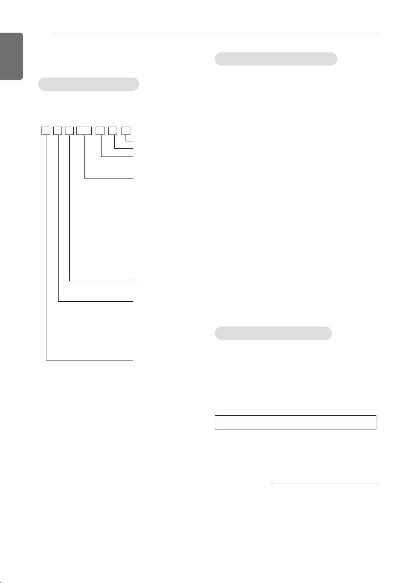
MODEL DESIGNATION
MODEL DESIGNATION
Product information
- Product Name : Air conditioner
- Model Name :
SQSM N B 015
- Additional Information : serial number is
refer to the barcode on the product.
- Refrigerant : R32 / R410A
Serial number
Chassis name
Indoor Unit / Outdoor Units
N : Indoor Unit
U : Outdoor Unit
Detailed product type only
for M- series models
AQ : Wall mounted Libero-R
SQ : Wall mounted Libero-E
AH* : ARTCOOL
AW* : ART COOL Mirror
AH : Ceiling Cassette
AHL : Ceiling Concealed Duct
(Low Static)
R : Refrigerant R32/R410A
PC : Standard plus (S)
Detailed product type for
U- / C- series models
L : Low Static
H : High COP
C : Econo
R : Refrigerant R32 / R410A
Nominal Capacity
Ex) 7 000 Btu/h Class → '07',
18 000 Btu/h Class → '18'
Product type
S : Wall mounted /
ARTCOOL mirror
J : Wall mounted
A : ARTCOOL
T : Ceiling Cassette
B, M : Ceiling Concealed Duct
V : Ceiling Suspended & floor
Q : Console
P : Floor Standing
Connectable Outdoor unit type
M : Indoor units only for
Multi systems
U : Indoor units only for
Single A systems
C : Common Indoor Unit for
Multi and Single CAC
Airborne Noise Emission
The A-weighted sound pressure emitted by
this product is below 70 dB.
** The noise level can vary depending on the
site.
The figures quoted are emission level and are
not necessarily safe working levels.
Whilst there is a correlation between the
emission and exposure levels, this cannot be
used reliably to determine whether or not
further precautions are required.
Factor that influence the actual level of
exposure of the workforce include the
characteristics of the work room and the other
sources of noise, i.e. the number of
equipment and other adjacent processes and
the length of time for which an operator
exposed to the noise. Also, the permissible
exposure level can vary from country to
country.
This information, however, will enable the
user of the equipment to make a better
evaluation of the hazard and risk.
Limiting concentration
Limiting concentration is the limit of Freon gas
concentration where immediate measures can
be taken without hurting human body when
refrigerant leaks in the air. The limiting
concentration shall be described in the unit of
kg/m3(Freon gas weight per unit air volume)
for facilitating calculation
Limiting concentration: 0.44kg/m3(R410A)
n Calculate refrigerant concentration
Refrigerant
concentration
(kg/m3)
Total amount of replenished
refrigerant in refrigerant facility (kg)
=
Capacity of smallest room where
indoor unit is installed (m3)

TIPS FOR SAVING ENERGY
TIPS FOR SAVING ENERGY
Here are some tips that will help you minimize the power consumption when you use the air
conditioner. You can use your air conditioner more efficiently by referring to the instructions
below:
• Do not cool excessively indoors. This may be harmful for your health and may consume more
electricity.
• Block sunlight with blinds or curtains while you are operating the air conditioner.
• Keep doors or windows closed tightly while you are operating the air conditioner.
• Adjust the direction of the air flow vertically or horizontally to circulate indoor air.
• Speed up the fan to cool or warm indoor air quickly, in a short period of time.
• Open windows regularly for ventilation as the indoor air quality may deteriorate if the air
conditioner is used for many hours.
• Clean the air filter once every 2 weeks. Dust and impurities collected in the air filter may block the
air flow or weaken the cooling / dehumidifying functions.
3
ENGLISH
For your records
Staple your receipt to this page in case you need it to prove the date of purchase or for warranty
purposes. Write the model number and the serial number here:
Model number :
Serial number :
You can find them on a label on the side of each unit.
Dealer’s name :
Date of purchase :
SAFETY INSTRUCTIONS
4
ENGLISH
SAFETY INSTRUCTIONS
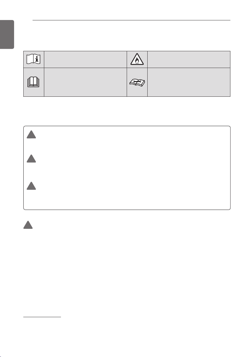
The following symbols are displayed on indoor and outdoor units.
Read the precautions in this manual
carefully before operating the unit.
This symbol indicates that the
Operation Manual should be read
carefully.
The following safety guidelines are intended to prevent unforeseen risks or damage
from unsafe or incorrect operation of the appliance.
The guidelines are separated into ‘WARNING’ and ‘CAUTION’ as described below.
This symbol is displayed to indicate matters and operations that can cause
!
risk. Read the part with this symbol carefully and follow the instructions in
order to avoid risk.
WARNING
!
This indicates that the failure to follow the instructions can cause serious
injury or death.
CAUTION
!
This indicates that the failure to follow the instructions can cause the
minor injury or damage to the product.
This appliance is filled with
flammable refrigerant (for R32)
This symbol indicates that a service
personnel should be handling this
equipment with reference to the
Installation Manual.
WARNING
!
• Installation or repairs made by unqualified persons can result in
hazards to you and others.
• The information contained in the manual is intended for use by a
qualified service technician familiar with safety procedures and
equipped with the proper tools and test instruments.
• Failure to carefully read and follow all instructions in this manual can
result in equipment malfunction, property damage, personal injury
and/or death.
• Compliance with national gas regulations shall be observed.
Installation
• Always perform grounding.
- Otherwise, it may cause electrical shock.

SAFETY INSTRUCTIONS
5
ENGLISH
• Don’t use a power cord, a plug or a loose socket which is damaged.
- Otherwise, it may cause a fire or electrical shock.
• For installation of the product, always contact the service center or a
professional installation agency.
- Otherwise, it may cause a fire, electrical shock, explosion or injury.
• Securely attach the electrical part cover to the indoor unit and the
service panel to the outdoor unit.
- If the electrical part cover of the indoor unit and the service panel of
the outdoor unit are not attached securely, it could result in a fire or
electric shock due to dust, water, etc.
• Always install an air leakage breaker and a dedicated switching board.
- No installation may cause a fire and electrical shock.
• Do not keep or use flammable gases or combustibles near the air
conditioner.
- Otherwise, it may cause a fire or the failure of product.
• Ensure that an installation frame of the outdoor unit is not damaged
due to use for a long time.
- It may cause injury or an accident.
• Do not disassemble or repair the product randomly.
- It will cause a fire or electrical shock.
• Do not install the product at a place that there is concern of falling
down.
- Otherwise, it may result in personal injury.
• Use caution when unpacking and installing.
- Sharp edges may cause injury.
• The appliance shall be stored in a room without continuously
operating ignition sources (for example: open flames, an operating gas
appliance or an operating electric heater.)
• Two or more people must lift and transport the product. Avoid
personal injury.
• Do not use means to accelerate the defrosting process or to clean,
other than those recommended by the manufacturer.
• Do not pierce or burn refrigerant cycle part.
• Be aware that refrigerants may not contain an odour.
• Keep any required ventilation openings clear of obstruction.
• The appliance shall be stored in a well-ventilated area where the room
size corresponds to the room area as specified for operation.

SAFETY INSTRUCTIONS
6
ENGLISH
• Refrigerant tubing shall be protected or enclosed to avoid damage.
• Flexible refrigerant connectors (such as connecting lines between the
indoor and outdoor unit) that may be displaced during normal
operations shall be protected against mechanical damage.
• A brazed, welded, or mechanical connection shall be made before
opening the valves to permit refrigerant to flow between the
refrigerating system parts.
• Mechanical connections shall be accessible for maintenance
purposes.
Operation
• Do not share the outlet with other appliances.
- It will cause an electric shock or a fire due to heat generation.
• Do not use the damaged power cord.
- Otherwise, it may cause a fire or electrical shock.
• Do not modify or extend the power cord randomly.
- Otherwise, it may cause a fire or electrical shock.
• Take care so that the power cord may not be pulled during operation.
- Otherwise, it may cause a fire or electrical shock.
• Unplug the unit if strange sounds, smell, or smoke comes from it.
- Otherwise, it may cause electrical shock or a fire.
• Keep the flames away.
- Otherwise, it may cause a fire.
• Take the power plug out if necessary, holding the head of the plug
and do not touch it with wet hands.
- Otherwise, it may cause a fire or electrical shock.
• Do not use the power cord near the heating tools.
- Otherwise, it may cause a fire and electrical shock.
• Do not open the suction inlet of the indoor/outdoor unit during
operation.
- Otherwise, it may electrical shock and failure.
• Do not allow water to run into electrical parts.
- Otherwise, it may cause the failure of machine or electrical shock.
• Hold the plug by the head when taking it out.
- It may cause electric shock and damage.
• Never touch the metal parts of the unit when removing the filter.
- They are sharp and may cause injury.

SAFETY INSTRUCTIONS
7
ENGLISH
• Do not step on the indoor/outdoor unit and do not put anything on it.
- It may cause an injury through dropping of the unit or falling down.
• Do not place a heavy object on the power cord.
- Otherwise, it may cause a fire or electrical shock.
• When the product is submerged into water, always contact the
service center.
- Otherwise, it may cause a fire or electrical shock.
• Take care so that children may not step on the outdoor unit.
- Otherwise, children may be seriously injured due to falling down.
• Use a vacuum pump or inert (nitrogen) gas when doing leakage test or
air purge. Do not compress air or oxygen, and do not use flammable
gases. Otherwise, it may cause fire or explosion.
- There is the risk of death, injury, fire or explosion.
• Do not turn on the breaker or power under condition that front panel,
cabinet, top cover, control box cover are removed or opened.
- Otherwise, it may cause fire, electric shock, explosion or death.
• Turn off all devices that cause fire when the refrigerant leaks.,
ventilate the room (example : opening window or using ventilation
unit), and contact with dealer who you purchased the unit.
• The installation of pipe-work shall be kept to a minimum.
• When mechanical connectors are reused indoors, sealing parts shall
be renewed.(for R32)
• When flared joints are reused indoors, the flare part shall be refabricated.(for R32)
CAUTION
!
Installation
• Install the drain hose to ensure that drain can be securely done.
- Otherwise, it may cause water leakage.
• Install the product so that the noise or hot wind from the outdoor unit
may not cause any damage to the neighbors.
- Otherwise, it may cause dispute with the neighbors.
• Always inspect gas leakage after the installation and repair of product.
- Otherwise, it may cause the failure of product.
• Keep level parallel in installing the product.
- Otherwise, it may cause vibration or water leakage.

SAFETY INSTRUCTIONS
8
ENGLISH
• Any person who is involved with working on or breaking into a
refrigerant circuit should hold a current valid certificate from an
industry-accredited assessment authority, which authorises their
competence to handle refrigerants safely in accordance with an
industry recognised assessment specification. (for R32)
• Wear adequate personal protection equipment (PPE) when installing,
maintaining or servicing the product.
• Pipe-work shall be protected from physical damage
• If anyone other than a licensed professional installs, repairs, or alters
LG Electronics air conditioning products, the warranty is voided.
- All costs associated with repair are then the full responsibility of the
owner.
Operation
• Avoid excessive cooling and perform ventilation sometimes.
- Otherwise, it may do harm to your health.
• Use a soft cloth to clean. Do not use wax, thinner, or a strong
detergent.
- The appearance of the air conditioner may deteriorate, change color,
or develop surface flaws.
• Do not use an appliance for special purposes such as preserving
animals vegetables, precision machine, or art articles.
- Otherwise, it may damage your properties.
• Do not place obstacles around the flow inlet or outlet.
- Otherwise, it may cause the failure of appliance or an accident.
• The appliance shall be stored so as to prevent mechanical damage
from occurring.
• Servicing shall only be performed as recommended by the equipment
manufacturer. Maintenance and repair requiring the assistance of
other skilled personnel shall be carried out under the supervision of
the person competent in the use of flammable refrigerants. (for R32)
• Dismantling the unit, treatment of the refrigerant oil and eventual
parts should be done in accordance with local and national standards.
• Periodic (more than once/year) cleaning of the dust or salt particles
stuck on the heat exchanger by using water.
• Means for disconnection must be incorporated in the fixed wiring in
accordance with the wiring rules.
TABLE OF CONTENTS
2 MODEL DESIGNATION
3 TIPS FOR SAVING ENERGY
4 SAFETY INSTRUCTIONS
10 INTRODUCTION
10 Features
11 INSTALLATION PARTS
11 INSTALLATION TOOLS
12 INSTALLATION MAP
13 INSTALLATION
13 Select the best Location
15 Fixing Installation Plate
15 Drill a Hole in the Wall
16 Flaring Work
17 Connecting the Piping
21 Connecting the Cables
23 Checking the Drainage
24 Te s t Running
25 Heating Only Mode
27 SMART DIAGNOSIS (Optional)
28 Manual the decor, air filter Assembly & Disassembly
TABLE OF CONTENTS
9
ENGLISH

INTRODUCTION
10
ENGLISH
INTRODUCTION
Features
Air outlet
Air filter
Front grille
Signal receiver
Display
On/Off button
(Vertical louver & Horizontal vane)
Air deflector
Air Intake Vents
Air Outlet Vents
* The feature can be changed according to type of model.
Plasmaster Ionizer
Connecting
Wires
Piping
Drain Hose
Base Plate
NOTE
• When mechanical connectors are reused indoors, sealing parts shall be renewed.

INSTALLATION PARTS
Name
Quantity Shape
Installation plate
1 EA
Cloth tape
Connector
1 EA
Type "A" screw
5 EA
Type "B" screw
2 EA
Type "C" screw
2 EA
Remote control
holder
1 EA
1 EA (5.0 kW)
2 EA (6.6 kW)
The feature can be changed according to type of model.
Type “B” screw
5.0 kW : ڸØ9.52 (3/8) ơ Ø12.7 (1/2)
6.6 kW : ڸØ9.52 (3/8) ơ Ø12.7 (1/2)
ڹØ15.88 (5/8) ơ Ø12.7 (1/2)
INSTALLATION PARTS
Screws for fixing panels are attached to decoration panel.
When Indoor unit (5.0/6.6 kW) is connected to the Multi Outdoor unit, use the connector.
11
ENGLISH
INSTALLATION TOOLS
Figure FigureName
Measuring tape, Knife
Torque wrench
Screw driver
Electric drill
Hole core drill
Spanner
Name
Multi-meter
Hexagonal wrench
Ammeter
Gas-leak detector
Thermometer,
Level
Flaring tool set

INSTALLATION MAP
12
ENGLISH
INSTALLATION MAP
Saddle
Installation plate
Sleeve
Bushing-Sleeve
Putty(Gum Type Sealant)
Bend the pipe as closely
on the wall as possible,
but be careful that it
doesn't break.
Vinyl tape (Wide)
• Apply after carrying out a
drainage test.
• To carry out the drainage
test, remove the air filters
and pour water into the heat
exchanger.
Gas side piping (Optional Parts)
Liquid side piping (Optional Parts)
Additional drain pipe
Vinyl tape (Narrow)
Drain hose
Connecting cable
(Optional Parts)
* The feature can be changed according a type of model.
* Work to the vinyl tape should up from below.
NOTE
• You should purchase the installation parts. (lt can be changed according to market)

INSTALLATION
INSTALLATION
Select the best Location
- There should not be any heat or steam near the unit.
- Select a place where there are no obstacles around of the unit.
- Make sure that condensation drainage can be conveniently routed away.
- Do not install near a doorway.
- Ensure that the interval between a wall and the left (or right) of the unit is more than 100 mm.
The unit should be installed as high as possible on the wall, allowing a minimum of 200 mm
from ceiling.
- Use a metal detector to locate studs to prevent unnecessary damage to the wall.
13
ENGLISH
More Than
100
More Than
2 300
* The feature can be changed according to type of model.
More Than
200
More Than
More Than
500
100
More Than
1 500
More Than
200
More Than
500
(Unit : mm)
NOTE
The gap between the indoor unit and ceiling is needed more than 200 mm for disassemble
the air filter.
- Do not use nails and/or screws to attach indoor units to sheetrock, drywall, plasterboard, tile,
plywood, or similar material types without proper anchors.Indoor units must be securely, and
properly mounted and anchored or damage and/or injury may result from improper installation.
Anchor
Anchor (mm) Screw (mm)
6 x 30 4 x 50

14
0
100
200
300
400
500
600
Amin (m2)
m (kg)
0 1.224 2 3 4 5 6 7 8
Floor standing
Wall mounted
Ceiling mounted
ENGLISH
INSTALLATION
Minimum floor area
(for R32)
- The appliance shall be installed, operated and stored in a room with a floor area larger than the
minimum area.
- Use the graph of table to determine the minimum area.
- m : Total refrigerant amount in the system
- Total refrigerant amount : factory refrigerant charge + additional refrigerant amount
- Amin : minimum area for installation
m (kg) Amin (m
< 1.224
1.224
1.4 16.82
1.6 21.97
1.8 27.80
2.2 41.53
2.4 49.42
2.6 58.00
2.8 67.27
3.2 87.86
3.4 99.19
3.6 111.20
3.8 123.90
4.2 151.36
4.4 166.12
Floor location
12.9
2 34.32
3 77.22
4 137.29
2
)
-
Floor location
m (kg) Amin (m
4.6 181.56
4.8 197.70
5 214.51
5.2 232.02
5.4 250.21
5.6 269.09
5.8 288.65
6 308.90
6.2 329.84
6.4 351.46
6.6 373.77
6.8 396.76
7 420.45
7.2 444.81
7.4 469.87
7.6 495.61
7.8 522.04
2
)
Wall mounted
m (kg) Amin (m
< 1.224
1.224
1.43
1.4 1.87
1.6 2.44
1.8 3.09
2 3.81
2.2 4.61
2.4 5.49
2.6 6.44
2.8 7.47
3 8.58
3.2 9.76
3.4 11.02
3.6 12.36
3.8 13.77
4 15.25
4.2 16.82
4.4 18.46
2
)
-
Wall mounted
m (kg) Amin (m
4.6 20.17
4.8 21.97
5 23.83
5.2 25.78
5.4 27.80
5.6 29.90
5.8 32.07
6 34.32
6.2 36.65
6.4 39.05
6.6 41.53
6.8 44.08
7 46.72
7.2 49.42
7.4 52.21
7.6 55.07
7.8 58.00
2
)
Ceiling Mounted
m (kg) Amin (m
< 1.224
1.224
0.956
1.4 1.25
1.6 1.63
1.8 2.07
2 2.55
2.2 3.09
2.4 3.68
2.6 4.31
2.8 5.00
3 5.74
3.2 6.54
3.4 7.38
3.6 8.27
3.8 9.22
4 10.21
4.2 11.26
4.4 12.36
2
)
-
Ceiling Mounted
m (kg) Amin (m
4.6 13.50
4.8 14.70
5 15.96
5.2 17.26
5.4 18.61
5.6 20.01
5.8 21.47
6 22.98
6.2 24.53
6.4 26.14
6.6 27.80
6.8 29.51
7 31.27
7.2 33.09
7.4 34.95
7.6 36.86
7.8 38.83
2
)

INSTALLATION
86
c
d
160
213
Framework of Indoor Unit
(Unit: mm)
131
C Type: 494 C Type: 504
Place a level on raised tab
Unit Outline
83
C Type: 134
Measuring Tape
Ø 65
83
Measuring Tape
Hanger
Ø 65
C Type: 150
(Unit : mm)
Right rear piping
Left rear piping
(Unit : mm)
194152
Ø 65
Right rear piping
Left rear piping
Ø 65
C Type : 134C Type : 98
C Type
C Type : 418 C Type : 418
Place a level on raised tab
Unit Outline
Installation Plate
15
ENGLISH
Fixing Installation Plate
The wall you select should be strong and solid
enough to prevent vibration
1 Mount the installation plate on the wall
with type "A" screws. If mounting the unit
on a concrete wall, use anchor bolts.
- Mount the installation plate horizontally
by aligning the centerline using Horizontal
meter.
SK/SJ Chassis
SR Chassis
SK/SJ Chassis
SR Chassis
2 Measure the wall and mark the centerline.
It is also important to use caution
concerning the location of the installation
plate. Routing of the wiring to power
outlets is through the walls typically.
Drilling the hole through the wall for piping
connections must be done safely.
Drill a Hole in the Wall
- Drill the piping hole with a Ø 65 mm hole
core drill. Drill the piping hole at either the
right or the left with the hole slightly slanted
to the outdoor side.
WALL
Indoor
Outdoor
5-7 mm
(3/16"~5/16")

16
Pipe
Reamer
Point down
ENGLISH
INSTALLATION
Flaring Work
Main cause for gas leakage is due to defect of
flaring work. Carry out correct flaring work in
the following procedure.
Cut the pipes and the cable
1 Use the piping kit accessory or the pipes
purchased locally.
2 Measure the distance between the indoor
and the outdoor unit.
3 Cut the pipes a little longer than measured
distance.
4 Cut the cable 1.5 m longer than the pipe
length.
Copper
pipe
NOTE
• Use the deoxidised copper as piping
materials to install.
Burrs removal
1 Completely remove all burrs from the cut
cross section of pipe/tube.
2 While removing burrs put the end of the
copper tube/pipe in a downward direction
while removing burrs location is also
changed in order to avoid dropping burrs
into the tubing.
90°
Slanted Uneven Rough
Putting nut on
- Remove flare nuts attached to indoor and
outdoor unit, then put them on pipe/tube
having completed burr removal.
(not possible to put them on after finishing
flare work)
Flare nut
Copper tube
Flaring work
1 Firmly hold copper pipe in a bar with the
dimension shown in below table.
2 Carry out flaring work with the flaring tool.
Pipe diameter
Inch (mm)
Ø 1/4 (Ø 6.35)
Ø 3/8 (Ø 9.52)
Ø 1/2 (Ø 12.7)
Ø 5/8 (Ø 15.88)
Ø 3/4 (Ø 19.05)
0.04~0.05 (1.1~1.3)
0.06~0.07 (1.5~1.7)
0.06~0.07 (1.6~1.8)
0.06~0.07 (1.6~1.8)
0.07~0.08 (1.9~2.1)
A inch (mm)
Wing nut type Clutch type
0~0.02
(0~0.5)
NOTE
• Temper grade of pipe: Annealed.
Bar
"A"
Copper pipe
<Wing nut type> <Clutch type>

INSTALLATION
17
ENGLISH
Check
1 Compare the flared work with the figure
by.
2 If a flared section is defective, cut it off
and do flaring work again.
Smooth all round
Even length
all round
Inside is shiny without scratches
= Improper flaring =
Surface
damaged
Cracked Uneven
Inclined
thickness
NOTE
• When flared joints are reused indoors,
the flare part shall be re-fabricated.
Connecting the Piping
1 Pull the cover at the bottom of the indoor
unit. Pull the cover ①→②.
2 Remove the cover from the indoor unit.
Indoor unit back side view
Right
Tubing holder
Left
Backwards
* The feature can be changed according to
type of model.
Assembly of chassis cover
1 Insert 4 hooks of the chassis cover into
gap of the chassis certainly.
3 Pull back the tubing holder.
4 Remove pipe port cover and positioning
the tubing
2 Push the 6 point hook to assemble chassis
cover. Push the chassis cover ①→②.
NOTE
To protect the chassis cover bended,
assembly chassis cover correctly.

18
ENGLISH
INSTALLATION
Good case
- Press on the tubing cover and unfold the
tubing to downward slowly. And then bend
to the left side slowly.
* The feature can be changed according to
type of model.
Bad case
- Following bending case from right to left
directly may cause damage to the tubing.
NOTE
Installation Information. For right piping.
Follow the instruction above.
Installation of Indoor Unit
1 Hook the indoor unit onto the upper
portion of the installation plate.( engage
the three hooks at the top of the indoor
unit with the upper edge of the installation
plate) Ensure that the hooks are properly
seated on the installation plate by moving
it left and right
Installation plate
2 Unlock the tubing holder from the chassis
and mount between the chassis and
installation plate in order to separate the
bottom side of the indoor unit from the
wall.
* The feature can be changed according to
type of model.
Tubing Holder
*
The feature can be changed according to the
type of model.

INSTALLATION
19
ENGLISH
Piping
1 Insert the connecting cable through the
bottom side of indoor unit and connect the
cable (You can see detail contents in
'Connecting the cables' section)
<Left side piping>
View
1(L) 2(N) 3(C)
<Left side piping>
Drain hose
Slide up the metal
plate cover
Terminal block
Connecting cable
Cable retainer
Tape
Connecting
cable
Drain hose
Connecting pipe
<Right side piping>
View
1(L) 2(N) 3(C)
Slide up the metal
plate cover
Terminal block
Connecting cable
Cable retainer
<Right side piping>
Tape
Connecting
cable
Drain hose
Connecting pipe
2 Secure the cable onto the control board
with the cable retainer.
3 Tape the tubing pipe, drain hose and the
connection cable. Be sure that the drain
hose is located at the lowest side of the
bundle. Locating at the upper side can
cause overflow from the drain pan through
the inside of the unit.

20
Vinyl tape(narrow)
Connection pipe
Connecting cable
Cloth tape
Wrap with cloth tape
Indoor unit pipe
Pipe
Gas Pipe
Liquid Pipe
Cutting Line
Cutting Line
Good Case Bad Case
* Tubing cutting line have to be upward.
ENGLISH
INSTALLATION
Connecting the installation pipe
and drain hose to the indoor unit.
1 Align the center of the pipes and
sufficiently tighten the flare nut by hand
Indoor unit tubing Flare nut Pipes
* When Indoor unit (6.6 kW) is connected to
the Multi Outdoor unit, use the connector.
2 Tighten the flare nut with a wrench.
Outside Diameter Torque
mm inch kgf.cm N.m
Ø6.35 1/4 180~250 17.6~24.5
Ø9.52 3/8 340~420 33.3~41.2
Ø12.7 1/2 550~660 53.9~64.7
Ø15.88 5/8 630~820 61.7~80.4
Spanner
(fixed)
Flare nut
Torque wrench
Indoor unit tubing
Connection
pipe
Wrap the insulation material
around the connecting portion.
1 Overlap the connection pipe insulation
material and the indoor unit pipe insulation
material. Bind them together with vinyl
tape so that there may be no gap.
Insulation material
2 Set the tubing cutting line upward.
Wrap the area which accommodates the
rear piping housing section with vinyl tape.
3 When needed to extend the drain hose of
indoor unit, assembly the drain pipe as
shown on the drawing.
Drain pipe
Adhesive
Indoor unit drain hose
Vinyl tape(narrow)
3 For left rear piping, bundle the piping and
drain hose together by wrapping them
cloth tape over the range within which
they fit into the rear piping housing
section.
Wrap with cloth tape
Pipe
Cloth tape
Drain hose
* Wrap the piping of the indoor unit that are
visible from the outside with vinyl tape.

INSTALLATION
NORMAL
CROSS-SECTIONAL
AREA 0.75 mm
2
20 mm
35 ± 5 mm
GN/YL
10 ± 3 mm
Power
connecting cable
21
ENGLISH
Connecting the Cables
Indoor unit
Connect the cable to the indoor unit by
connecting the wires to the terminals on the
control board individually according to the
outdoor unit connection. (Ensure that the color
of the wires of the outdoor unit and the
terminal No. are the same as those of the
indoor unit.)
Insert the connecting cable through the bottom side of indoor unit and connect the cable.
(1) Open the Decor
(2) Unscrew the screw of C/Box
(3) Slide up the Metal Plate Cover
(4) Connect the connecting cable
(5) After complete connect the cables, should
assemble the Metal Plate Cover by screw.
1(L) 2(N) 3(C)
NOTE
The power cord connected to unit should
be selected according to the following
national wiring regulations. The supply
cords of parts of appliances for outdoor
use shall not be lighter than
polychloroprene sheathed flexible cord.
(code designation 60245 IEC 57, H05RN-F)
CAUTION
!
The connecting cable connected to the
indoor and outdoor unit should be
complied with the following specifications
(This equipment shall be provided with a
cord set complying with the national
regulation).
Decor
Power
Power
connecting cable
connecting cable
* The feature can be changed according a
type of model.
CAUTION
!
- The circuit diagram is a subject to
change without notice.
- The earth wire should be longer than the
common wires.
- When installing, refer to the circuit
diagram on the chassis cover.
- Connect the wires firmly so that they
may not be pulled out easily.
- Connect the wires according to color
codes, referring to the wiring diagram.
If the supply cord is damaged, it must be
replaced by a special cord or assembly
available from the manufacturer of its
service agent.

22
Power wire
Round pressure terminal
Connect same thickness
wiring to both sides.
It is forbidden to
connect two to one
side.
It is forbidden to
connect wiring of
different thicknesses.
ENGLISH
INSTALLATION
Precautions when laying power
wiring
Use round pressure terminals for connections
to the power terminal block.
When none are available, follow the
instructions below.
- Do not connect wiring of different
thicknesses to the power terminal block.
(Slack in the power wiring may cause
abnormal heat.)
- When connecting wiring which is the same
thickness, do as shown in the figure below.
- For wiring, use the designated power wire
and connect firmly, then secure to prevent
outside pressure being exerted on the
terminal block.
- Use an appropriate screwdriver for tightening
the terminal screws. A screwdriver with a
small head will strip the head and make
proper tighterning impossible.
- Over-tightening the terminal screws may
break them.
CAUTION
!
According to the confirmation of the above
conditions, prepare the wiring as follows.
1 Never fail to have an individual power
circuit specifically for the air conditioner.
As for the method of wiring, be guided
by the circuit diagram posted on the
inside of control cover.
2 The screw which fasten the wiring in the
casing of electrical fittings are liable to
come loose from vibrations to which the
unit is subjected during the course of
transportation. Check them and make
sure that they are all tightly fastened. (If
they are loose, it could cause burn-out of
the wires.)
3 Specification of power source.
4 Confirm that electrical capacity is
sufficient.
5 See that the starting voltage is
maintained at more than 90 percent of
the rated voltage marked on the name
plate.
6 Confirm that the cable thickness is as
specified in the power source
specification. (Particularly note the
relation between cable length and
thickness.)
7 Always install an earth leakage circuit
breaker in a wet or moist area.
8 The following would be caused by
voltage drop.
- Vibration of a magnetic switch, which
will damage the contact point, fuse
breaking, disturbance of the normal
function of the overload.
9 The means for disconnection from a
power supply shall be incorporated in the
fixed wiring and have an air gap contact
separation of at least 3 mm in each
active(phase) conductors.
10 Open the terminal cover block before
connecting the indoor side wire.

INSTALLATION
Downward slope
23
ENGLISH
Finishing the indoor unit
installation
1 Mount the tubing holder in the original
position.
2 Ensure that the hooks are properly seated
on the installation plate by moving it left
and right.
3 Press the lower left and right sides of the
unit against the installation plate until the
hooks engage into their slots (clicking
sound).
4 Finish the assembly by screwing the unit
to the installation plate by using two
pieces of type "C" screws. And assemble a
chassis cover.
Checking the Drainage
To check the drainage.
1 Pour a glass of water on the evaporator.
2 Ensure the water flows through the drain
hose of the indoor unit without any
leakage and goes out the drain exit.
Connecting area
drain hose
Leakage
checking
Drain pan
Drain
hose
Leakage
checking
Type 'C' screw
* The feature can be changed according to
type of model.
CAUTION
!
The indoor unit can be dropped from the
wall, the indoor unit is not screwed
correct position on the install plate.
To avoid the gap between the indoor unit
and wall , screw the indoor unit to the
install plate correctly.
* The feature can be changed according to
type of model.
Drain piping
1 The drain hose should point downward for
easy drain flow.

24
Do not raise
Water
leakage
Tip of drain hose
dipped in water
Water
leakage
Ditch
Less than
50mm gap
Accumulated
drain water
Air
Waving
Water
leakage
ENGLISH
INSTALLATION
2 Do not make drain piping like the
following.
* The feature can be changed according to
type of model.
Evaluation of the performance
Operate the unit for 15~20 minutes, then
check the system refrigerant charge:
1 Measure the pressure of the gas side
service valve.
2 Measure the air temperature from inlet and
outlet of air conditioner.
3 Ensure the difference between the inlet
and outlet temperature is more than 8 °C.
4 For reference; the gas side pressure at
optimum condition is shown on table
(cooling)
The air conditioner is now ready to use.
Test Running
- Check that all tubing and wiring are properly
connected.
- Check that the gas and liquid side service
valves are fully open.
Prepare remote controller
1 Remove the battery cover by pulling it
according to the arrow direction.
2 Insert new batteries making sure that the
(+) and (–) of battery are installed correctly.
3 Reattach the cover by pushing it back into
position.
NOTE
• Use 2 AAA(1.5 V) batteries. Do not use
rechargeable batteries.
• Remove the batteries from the remote
controller if the system is not used for a
long time
Inlet temperature
Discharge air
* The feature can be changed according a
type of model.
Discharge
temperature

INSTALLATION
25
ENGLISH
Test operation
- If you press and hold the On/Off button for
3 – 5 seconds instead of 6 seconds, the unit
will switch to the test operation.
- In the test operation, the unit blows out
strong air for cooling for 18 minutes and then
returns to the factory default settings.
NOTE
If the actual pressure is higher than shown,
the system is most likely over-charged, and
charge should be removed. If the actual
pressure are lower than shown, the system
is most likely undercharged, and charge
should be added.
Pump Down
This is performed when the unit is relocated
or the refrigerant circuit is serviced.
Pump Down means collecting all refrigerant into
the outdoor unit without the loss of refrigerant.
Pump Down Procedure
- Connect a low-pressure gauge manifold
hose to the charge port on the gas side
service valve.
- Open the gas side service valve halfway and
purge the air in the manifold hose using the
refrigerant.
- Close the liquid side service valve(all the
way).
- Turn on the unit's operating switch and start
the cooling operation.
- When the low-pressure gauge reading
becomes 1 to 0.5 kg/cm
P.S.I.G.), fully close the gas side valve and
then quickly turn off the unit. Now Pump
Down procedure is completed, and all
refrigerant is collected into the outdoor unit.
2
G(14.2 to 7.1
Heating Only Mode
Heating Only Mode switching
function setup
1 Supply the power to the unit with no
functions active.
2 Enter the Installer Code and set the code
to 47.
3 Press to select the code No.47 then,
check if buzzer beeps.
4 Cut the power to the unit.
5 Turn back on the power to the unit after 30
seconds.
NOTE
Be sure to perform Pump Down procedure
in the cooling mode.
WARNING
!
It may cause explosion or injury.
After pump down, power must be turned
off before removing the pipe. When
operating this product without connecting
the pipe, there will be high pressure inside
the compressor due to the entry of air,
possibly causing explosion or injury.

26
ENGLISH
INSTALLATION
Heating Only Mode switching
function disable setup
1 Supply the power to the unit with no
functions active.
2 Enter the Installer Code and set the code
to 48.
3 Press to select the code No.48 then,
check if buzzer beeps.
4 Cut the power to the unit.
5 Turn back on the power to the unit after 30
seconds.
* How to enter the installer mode
Press Reset Button and ‘A’ Button ( )
Press
SETUP
A
NOTE
- Once the function is set up, Cooling,
Dehumidification Auto Change over
cannot be used.
- Once the function is disable it will return
to its normal state.
- Code cannot be entered when it is in
operation mode. It must be OFF state to
enter code.
- Even if able to enter code in ON state, it
won’t function if the code is not entered
in OFF state.
- At Heating Only Mode, if the product
gets turned off while the wireless
remote control is set at other than
heating / blowing, the product will not
get turned back on. Turn off the product
after the wireless remote control is set at
heating / blowing and then turn back on.
* How to set the code
Set the code you want by pressing TEMP
button (
_
_
) and press .
10 digit
1 digit

INSTALLATION
27
ENGLISH
SMART DIAGNOSIS
(Optional)
Diagnosis of operating information
1 Enter the Installer Code and set the code
to 57.
2 Click the “Receive” button on the main
screen of LG AC Smart Diagnosis App on
your smart phone.
3 Press and hold your smart phone close
to the indoor unit.
4 Receive the buzzer beeps from indoor unit
with your smart phone.
5 The diagnosis of operating information will
be displayed on the screen of your smart
phone.
Diagnosis of error information
1 Enter the Installer Code and set the code
to 58.
2 Click the “Receive” button on the main
screen of LG AC Smart Diagnosis App on
your smart phone.
3 Press and hold your smart phone close
to the indoor unit.
4 Receive the buzzer beeps from indoor unit
with your smart phone.
5 The diagnosis of operating information will
be displayed on the screen of your smart
phone.
* How to enter the installer mode
Press Reset Button and ‘A’ Button ( )
Press
* How to set the code
Set the code you want by pressing TEMP
button ( _) and press .
_
SETUP
10 digit
1 digit
NOTE
- Be sure to keep ambient noise to a
minimum or the smart phone may not
correctly receive the buzzer beeps from
the indoor unit.
- Initialization of diagnosis data may take
approximately 1 minute after supplying
the AC power .
- The code No. 57 is used for confirming
the diagnosis data which is updated on
while the indoor unit is operating
- The code No. 58 is used for confirming
the diagnosis data which is the occurred
time of Error Code.
A

INSTALLATION
28
ENGLISH
Manual the decor, air filter Assembly & Disassembly
Disassemble the decor
1 Turn off the power and unplug the power cord.
2 Pull the decor at the bottom of the indoor unit.
3
Remove the decor from the indoor unit.
Assemble the decor
1
Turn off the power and unplug the power cord.
2 Insert 3 or 4 hooks of the decor into gap of
the indoor unit certainly.
Disassemble the air filter
1
Turn off the power and unplug the power cord.
2
Hold the knob of the air filter, Lift it up slightly.
3 Hold the knob of the air filter, lift it up
slightly and remove it from the unit.
Assemble the air filter
1
Turn off the power and unplug the power cord.
2 Insert the hooks of the air filter into the
front grille.
3
Push down hooks to assemble the air filter.
3
Push the nooks to assemble the decor.
CAUTION
!
The air filter can be broken when it is
bended.
4 Check side of the front grille for the air filter
assembled correctly.
NOTE
lf the air filter is not assembled correctly, Dust
and other substance come into the indoor unit.
lf look at the indoor unit from higher than it,
can assemble the air filter easily.

INSTALLATION
29
Precautions about installation in regions with extreme snowfall and cold
temperatures
To ensure the outdoor unit operates properly, certain measures are required in locations where there
is a possibility of heavy snowfall or severe wind chill or cold :
1 Prepare for severe winter wind chills and heavy snowfall, even in areas of the country where these
are unusual phenomena.
2 Position the outdoor unit so that its airflow fans are not buried by direct, heavy snowfall.
If snow piles up and blocks the airflow, the system may malfunction.
3 Remove any snow that has accumulated 100 mm or more on the top of the outdoor unit.
4 Place the outdoor unit on a raised platform at least 500 mm higher than the aver- age annual
snowfall for the area. If the frame width is wider than the outdoor unit, snow may accumulate.
5 Install a snow protection hood.
6 To prevent snow and heavy rain from entering the outdoor unit, install the suction and dis- charge
ducts facing away from direct winds.
7 Additionally, the following conditions should be taken into consideration when the unit operates in
defrost mode:
- If the outdoor unit is installed in a highly humid environment (near an ocean, lake, etc.), en- sure
that the site is well-ventilated and has a lot of natural light. (Example: Install on a rooftop.)
ENGLISH

30
ENGLISH

 Loading...