

LG MG-5507D Service Manual

MICROWAVE OVEN
SERVICE MANUAL
MODEL: MG-5507D
CAUTION
BEFORE SERVICING THE UNIT, READ THE
SAFETY PRECAUTIONS IN THIS MANUAL.
CAUTIONS
• Be sure to check microwave leakage prior to
servicing the oven if the oven is operative prior to
servicing.
• The service personnel should inform the
manufacture importer, or assembler of any
certified oven unit found to have a microwave
emission level in excess of 5 mW/cm
2
and should
repair any unit found to have excessive emission levels
at no cost to the owner and should ascertain the cause
of the excessive leakage. The service personnel
should instruct the owner not to use the unit until the
oven has been brought into compliance.
• If the oven operates with the door open, the service
personnel should:
- Tell the user not to operate the oven.
- Contact the manufacturer.
• The service personnel should check all surface and
vent openings for microwave leakage.
• Check for microwave leakage after every servicing.
The power density of the microwave radiation leakage
emitted by the microwave oven should not exceed
4 mW/cm
2
. Always start measuring of an unknown field
to assure safety for operating personnel from radiation
leakage.
MEASURING MICROWAVE ENERGY
LEAKAGE
• Pour 275±15cc of 20±5°C(68±9°F) water in a beaker
which is graduated to 600 cc, and place the beaker
on the center of the turntable.
• Set the energy leakage monitor to 2,450 MHz and
use it following the manufacturer's recommended
test procedure to assure correct result.
• When measuring the leakage, always use the 2inch (5cm) spacer supplied with the probe.
• Operate the oven at its maximum output.
• Measure the microwave radiation using and
electromagnetic radiation monitor by holding the
probe perpendicular to the surface being measured
Move probe along shaded area
Probe scanning speed
Less than 2.5 cm/sec
( 1in/sec)
5-1
SERVICE INFORMATION
TOOLS AND MEASURING INSTRUMENTS
MICROWAVE LEAKAGE TEST
NECESSARY TOOLS
Tools normally used for TV servicing are sufficient.
Standard tools are listed below.
• Diagonal pliers
• Long nose pliers
• Phillips screwdriver
• Flat blade screwdriver
• Wrench (size 5mm)
• Nutdriver (size 5mm)
• Adjustable wrench
• Soldering iron
• Solder
• Vinyl insulation tape
• Polishing cloth
NECESSARY MEASURING INSTRUMENTS
• TESTER(VOLTS-DC, AC., Ohmmeter)
• Microwave survey meter
- Holaday HI-1500
HI-1501
- Narda 8100
8200
• Inch scale
• 600 cc non conductive material beaker (glass or plastic),
inside diameter: approx. 8.5 cm(3
1
/2 in.)
• Cylindrical and made of borosilicate glass vessel.
max. thickness: 3 mm
outside diameter: approx. 190mm
height: approx. 90mm
• Glass thermometer: 100°C or 212°F (1 deg scale)
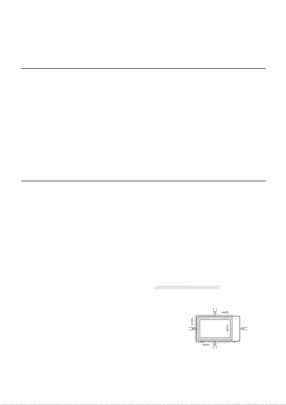
MEASUREMENT WITH OUTER CASE
REMOVED
• When you replace the magnetron, measure for
microwave energy leakage before the outer case is
installed and after all necessary components are
replaced or adjusted.
Special care should be taken in measuring the
following parts. (Circled area of below Fig.)
- Around the magnetron
- The waveguide
MEASUREMENT WITH A FULLY
ASSEMBLED OVEN
• After all components, including the outer case, are fully
assembled, measure for microwave energy leakage
around the door viewing window, the exhaust opening,
and air inlet openings.
• Microwave energy leakage must not exceed the values
prescribed below.
NOTE: Leakage with the outer case removedless than
5 mW/cm.sq. Leakage for a fully assembled
oven (Before the latch switch (primary) is
interrupted) with the door in a slightly opened
position-less than 2 mW/cm.sq.
NOTES WHEN MEASURING
• Do not exceed meter full scale deflection.
• The test probe must be removed no faster than
1 inch/sec (2.5 cm/sec) along the shaded area,
otherwise a false reading may result.
• The test probe must be held with the grip portion of the
handle.
A false reading may result if the operator's hand is
between the handle and the probe.
• When testing near a corner of the door, keep the probe
perpendicular to the surface making sure the probe
horizontally along the oven surface, this may possibly
cause probe damage.
RECORD KEEPING AND NOTIFICATION
AFTER MEASUREMENT
• After adjustment and repair of any microwave energy
interruption or microwave energy blocking device,
record the measured values for future reference. Also
enter the information on the service invoice.
• The microwave energy leakage should not be more
than 4 mW/cm.sq. after determining that all parts are in
good condition, functioning properly and genuine
replacement parts which are listed in this manual have
been used.
• At least once a year, have the electromagnetic energy
leakage monitor checked for calibration by its
manufacturer.
5-2
WARNING : AVOID CONTACTING ANY
HIGH VOLTAGE PARTS
• Microwave power output measurement is made with
the microwave oven supplied at its rated voltage and
operated at its maximum microwave power setting with
a load of (1000±5) g of potable water.
• The water is contained in a cylindrical borosilicate glass
vessel having a maximum material thickness of 3 mm
and an outside diameter of approximately 190mm.
• The oven and the empty vessel are at ambient
temperature prior to the start of the test.
• The initial temperature (T1) of the water is (10±2)°C It
is measured immediately before the water is added to
the vessel. After addition of the water to the vessel,
the load is immediately placed on the center of the
turntable which is in the lowest position and the
microwave power switched on.
• The time T for the temperature of the water to rise by a
value ∆ T of (10±2)°K is measured, where T is the time
in seconds and ∆T is the temperature rise. The initial
and final water temperatures are selected so that the
maximum difference between the final water
temperature and the ambient temperature is 5°K.
• The microwave power output P in watts is calculated
from the following formula :
4187 x (∆T)
T
is measured while the microwave generator is
operating at full power. Magnetron filament heat-up
time is not included. (about 3 sec)
• The water is stirred to equalize temperature throughout
the vessel, prior to measuring the final water
temperature.
• Stirring devices and measuring instruments are
selected in order to minimize addition or removal of
heat.
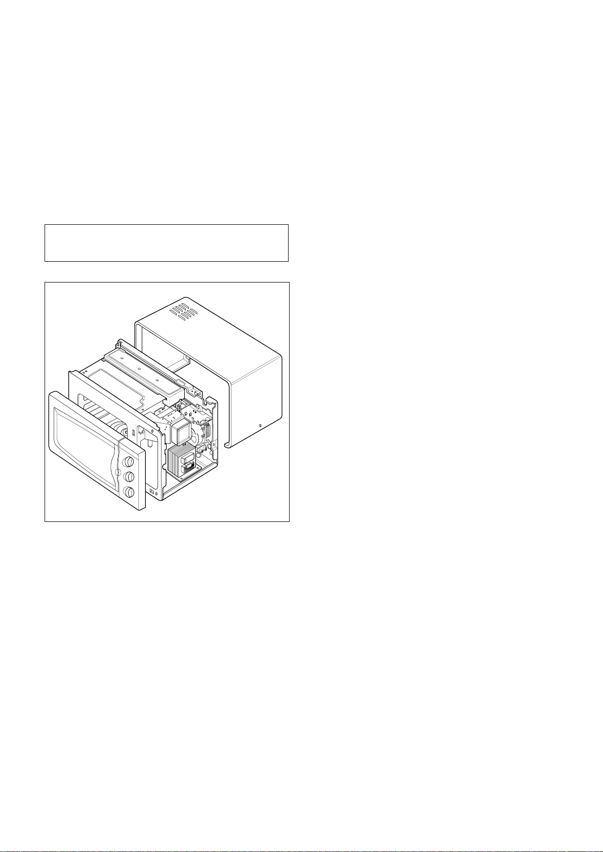
A. OUTER CASE REMOVAL
1) Disconnect the power supply cord from the outlet.
2) Remove the screws from the rear and along side
edges of the case.
The outer case must be moved backward to be lifted
off.
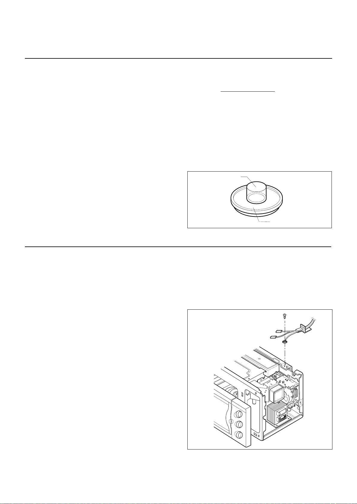
B. POWER SUPPLY CORD
1) Remove the outer case.
2) Disconnect two terminals, and remove one screw of
the earth terminal.
CAUTION: DISCHARGE THE HIGH VOLTAGE
CAPACITOR BEFORE SERVICING
(refer to page 2-1)
C. CONTROL PANEL ASSEMBLY
1) Disconnect the leadwire from the Timer motor and the
mode select switch.
2) Remove the screws for the earth and securing the
control panel.
3) Lift control panel ASS’Y from the oven by the tab
unhooked.
5-3
WATER LOAD
TURNTABLE
MEASUREMENT OF MICROWAVE POWER OUTPUT
P =
DISASSEMBLY AND ADJUSTMENT
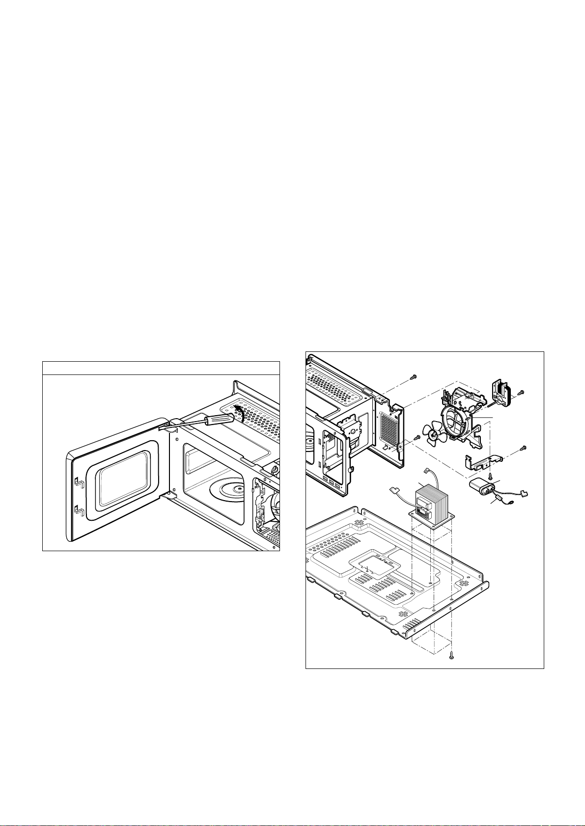
D. DOOR GROSS ASSEMBLY REMOVAL
1) Open the door.
2) Remove the choke cover very carefully with a flatblade screwdriver.
CAUTION : Be careful not to damage door seal plate
by screwdriver.
3) Lift up and push the door.
NOTE:
1. After replacing the door, be sure to check that the
primary switch, monitor switch, and secondary switch
operate normally.
2. After replacing the door, check for microwave energy
leakage with a survey meter. Microwave energy must
be below the limit of 5 mW/cm. (with a 275 ml water
load)
3. When mounting the door assembly to the oven
assembly, be sure to adjust the door assembly parallel
to the chassis. Also adjust so the door has no play
between the inner door surface and oven frame
assembly. If the door assembly is not mounted
properly, microwaves may leak from the clearance
between the door and the oven.
E. HIGH VOLTAGE TRANSFORMER
REMOVAL
1) Discharge the high voltage capacitor.
2) Disconnect the leadwire from magnetron, high voltage
transformer, and capacitor.
3) Remove the screw holding the high voltage
transformer to the baseplate.
F. FAN MOTOR ASSEMBLY REMOVAL
1) Discharge the high voltage capacitor.
2) Disconnect the leadwire from fan motor, noise filter
and high voltage capacitor.
3) Remove the two screws holding the the suction guide
ASS’Y to the oven cavity and remove the high voltage
diode earth screw.
4) Remove the screw of the capacitor bracket.
5) Remove the two screws holding the fan motor ASS’Y
to the suction guide ASS’Y.
G. HIGH VOLTAGE CAPACITOR AND
DIODE REMOVAL
1) Discharge the high voltage capacitor.
2) Disconnect the leadwire from fan motor, noise filter
and high voltage capacitor.
3) Remove the screw holding the suction guide ASS’Y to
the oven cavity and remove the high voltage diode
earth screw.
4) Remove the screw holding the high voltage capacitor
bracket.
5-4
Remove choke cover
H.V.
Transformer
H.V.
Diode
H.V.
Capacitor
Suction
Guide
Fan Motor ASS'Y
 Loading...