

Page 1

Owner's Manual
Laser Display install guide
Please read the safety information carefully before using the product.
P/NO : MFL67652408(1302-REV00)
www.lg.com
Page 2
Safety Precautions
2
Safety Precautions
Please take note of the safety instructions to prevent any potential accident or misuse
of the product.
Safety precautions are given in two forms, i.e. Warning and Caution as detailed be-
low.
WARNING: Failure to follow the instructions may cause serious injury and even
death.
CAUTION: Failure to follow the instructions may cause minor injury or damage to
the product.
Read the owner's manual carefully and keep it to hand.
Installation
WARNING
The product should be installed by a
qualified professional specified by the
retail store.
- The product installation by a nonqualified personnel is dangerous
and may cause personal injury.
The product should be installed
where its weight can be supported.
- Otherwise, the product may fall and
cause personal injury.
When moving or replacing the prod-
uct after installation, contact a qualified installer specified by the retail
store.
- If an unqualified person moves and
installs the product, this may cause
safety issues as this task requires
the special technique.
Do not hang on the product or apply
shock to the product.
- The product may fall and cause
injury.
CAUTION
Follow the instructions in the manual
to install the product.
- Otherwise, it may cause serious
injury or damage to the product.
When installing the product or ad-
justing the height of the product, two
or more people are needed.
- If you do it by yourself, you may
drop the product causing personal
injury or damage to the product.
When installing the product, check
whether the wall is strong enough to
hold the product and use the anchors and screws provided.
- Otherwise, they may not bear the
weight of the product causing safety
issues.
Page 3

When drilling the holes in the wall,
make sure you use a drill and a drill
bit with the specified size of diameter.
Ensure that you also follow the instructions regarding the depth of the
holes.
- Otherwise, the product may be
installed improperly causing safety
issues.
Do not clean the product with wet
towels, and do not use a heater or
humidifier underneath the product.
- Moisture permeating into the
product, steam or heat may result in
fire, electric shock or damage to the
product.
Keep the product away from sprin-
klers, sensors, high-tension wires
and power sources. Do not install the
product in a location where vibrations
or shock impacts are likely to occur.
Wear working gloves when installing
the product. Do not use bare hands.
- Otherwise, it may cause personal
injury.
Safety Precautions
3
Page 4
PREPARATION
4
PREPARATION
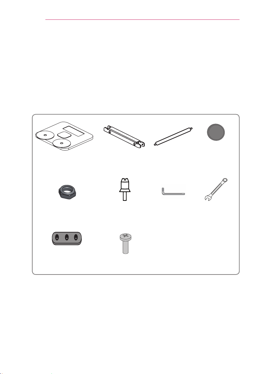
Accessories
Check the accessories provided with the product.
The picture may be different from the actual product.
Accessories are subject to change without prior notice in order to improve the performance of the product. New accessories may be added or old ones may be removed.
Ez Bracket Fixed component
Fixing nuts, 2EA Guide pins, 2EA
Plate
Screw 1EA
(M5 x 12 mm)
Connection rods,
Adjustable
wrench (3 mm)
Preparations
Ø8 mm drill bit for concrete, leveler, tapeline, driver, tape
2EA
Rubber
packings, 6EA
Spanner
Page 5
INSTALLATION
INSTALLATION
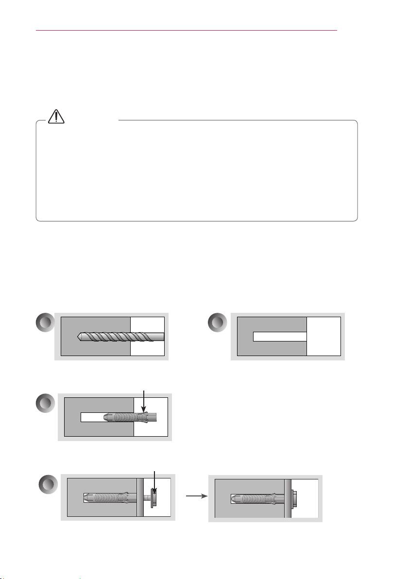
How to fix anchors and screws
CAUTION
Check the wall materials and the thickness of finishing materials.
You can use the anchors and bolts provided with the Laser Display set for walls
made from concrete, lightweight concrete, soft fieldstone, hard fieldstone, brick
or cellular blocks.
When installing it on a wall not specified in this manual, make sure each fixing
point withstands an uplifting load of 70 kgf (686 N) and a shearing load of 100
kgf (980 N) or more.
(Attach a plate such as plywood to strengthen the wall before installation.)
a. At each anchor position, use a 8 mm drill bit to make a hole with a depth of
80 mm - 100 mm.
b. Clean the holes.
c. Insert the anchors provided into each hole.
(Use a hammer when inserting the anchor.)
d. Fix a part in place by aligning it with the screw hole.
Tighten the screw with a torque 45 kgf/cm - 60 kgf/cm or higher.
a
b
5
Drilling hole
c
Inserting anchor
d
Screw for fixing ring and
space steel
Cleaning hole
Anchor
Fixing ring and space steel
Screw for fixing ring and space steel
Page 6
INSTALLATION
6
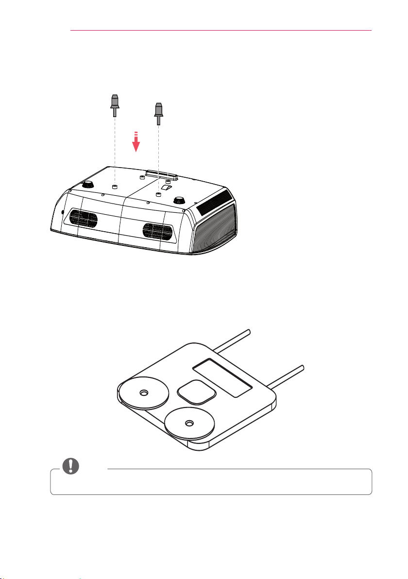
Installation Procedure (Stand Type)
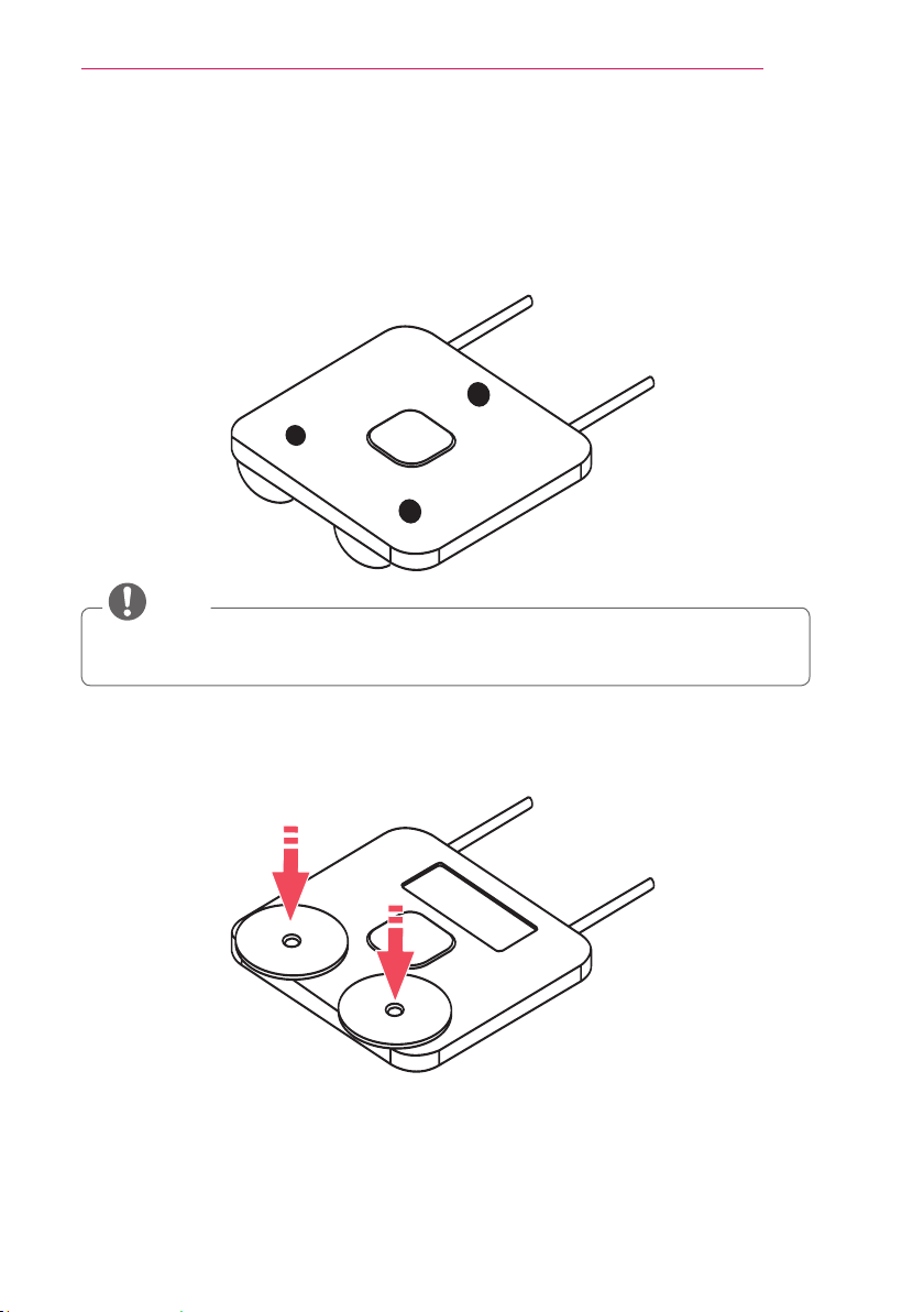
1 Install the guide pins at the bottom of the set.
2 Connect the connection rod to the Ez bracket main unit and place it on a table,
without the fixed components, at the center of the screen.
NOTE
Do not assemble the fixed components to the unit yet.
Page 7
INSTALLATION
3
If the Ez bracket does not stay level, attach a rubber to the bottom of the bracket to
make it level.
(If you cannot make it level using a rubber, remove or add a plate. To add a plate,
make sure to use screws that came with the product.)
NOTE
If you cannot make it level by attaching a rubber, remove or add a plate. (To add a
plate, make sure to use screws that came with the product.)
7
4
Place the Laser Display onto the Ez bracket by aligning the guide pins and the holes
on the adjustable bracket.
Page 8
INSTALLATION
390 mm
Up
Down
8
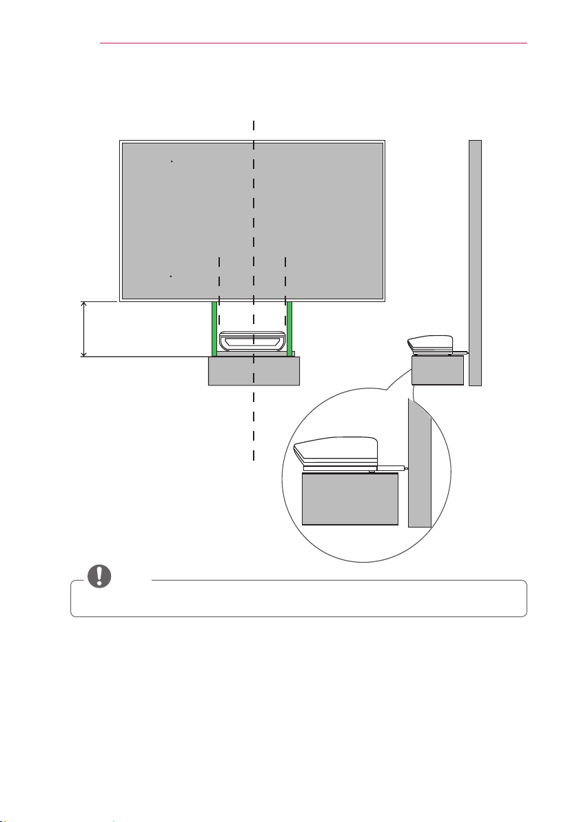
5 Attach 390 mm of guide tapes to the top of the table referring the sides of Laser
Display so that the tapes are vertically upward.
Center line
Paper screen
390 mm Guide tape
Adjustable bracket
Table
NOTE
The figure above illustrates the fixed components which are not fixed yet.
6 Attach the paper screen above the tape. Refer to the guide tape to keep it level.
(The paper screen helps to easily install the adjustable bracket and bore holes in the wall.)
7 Place the Ez bracket with the Laser Display installed close to the wall.
8 Turn on the power on the Laser Display.
Page 9

INSTALLATION
9 Adjust the Ez bracket by following the Laser Display screen adjustment steps to
make the size of the projection screen equal to that of the paper screen. Position
the projection screen, aligning it with the black line of the paper screen.
(If there is a gap larger than 10 mm between the projection screen and the paper
screen, mark the screen position on the paper screen and make holes in four
places.)
CAUTION
When adjusting the screen with the paper screen, do not move the Ez bracket to
the left or right.
If it is necessary to move the bracket, detach the paper screen first. If you make
too many left/right adjustments, further adjustments may be not be possible due
to lack of marginal space when actually attaching and using the screen.
Projection screen
9
Paper screen
10 mm
Page 10

INSTALLATION
40 mm
10
10 Place guide tape on both sides of the paper screen in parallel with it. Position the
tape about 40 mm above the paper screen.
The tape is used as a reference guide to help easy screen installation.
Tape
Up
Ф 8
Down
11 Make holes using an 8 mm drill at specified positions and detach the paper screen.
12 Insert the anchors into the four holes.
13 Fix rings into the two upper holes and space steels to the two lower holes using
8 mm bolts.
Attach three magnets to the space steels fixed at the bottom.
Space steel
3 magnets
Page 11

INSTALLATION
14 Mark the end of Ez bracket rod on the wall.
(Mark the positions of the holes where the Ez brackets will be fixed.)
15 Remove the Laser Display set and Ez bracket from the table.
16 16 Position both holes of the fixed component against the marks on the wall and
mark the positions where the anchors will be inserted.
Wall
11
Mark on wall
Mark on wall
Page 12

INSTALLATION
12
17 Make holes in the two locations marked with arrows using an 8 mm drill.
18 Detach the paper screen and insert the anchors into the two holes.
19 19 Secure the fixed component using two 8 mm screws.
(If adjustment is not possible due to lack of marginal space while aligning an
image to the screen, loosen the screws and move the fixed component slightly to
the left or right.)
20 Fix the Ez bracket to the fixed component using the spanner and fixing nuts
provided with the product.
21 Place the Laser Display set onto the Ez bracket.
Page 13

INSTALLATION
Down
Up
22 Two people must lift the screen above the guide tape and hang it on the rings.
Keep the arrows pointing down.
CAUTION
Align the top of screen with the top of the tape and the left and right sides of
the screen with the tape. Hang the bracket on the rings by lowering the screen
carefully. If the screen is upside down, the screen will be dark and no image will
be displayed.
Tape
Up
Down
13
Magnet
Page 14

INSTALLATION
14
CAUTION
• If the screen is tilted when pulling it down, it may not fix to the bracket and could
result in damage to the screen.
23 Move the screen in all directions to check that it is securely hung on the rings.
24 Check whether the screen stays level using a leveler.
Page 15

INSTALLATION
25 Check that the right and left sides of the screen are parallel to the wall using a
leveler.If it is not parallel to the wall, calibrate the screen angle using the space
steels.
Unhang the screen and remove the fixed rings and magnets.
Calculate the amount of space steels to be used using the formula below, locate
the space steels between the wall and the rings/magnets and fix them again, and
align the screen to be parallel to the wall.
(0.1° → 2 mm → 1 space steel)
15
<Left side> <Right side>
❶
❷
❸
Horizontal Vertical
Horizontal Vertical
❶
0.2 ° Move to the next hole 0.1 Insert 2 space steels
❷
0.3°-0.4 °Skip 2-3 holes 0.2 Insert 3-4 space steels
❸
Page 16

INSTALLATION
16
If the screen is not parallel to the wall
NOTE
If the top of the screen is tilted to the wall, add space steels at the top and, if the bottom of
screen is tilted to the wall, add magnets at the bottom to make the screen parallel to the wall.
If the screen does not stay level
If you want to move the screen vertically or if it does not stay level, remove the
screen and adjust the bracket on the back. Loosen the six screws of the bracket to
move it and fasten the screws again.
(4 mm of distance between slots = 0.14°)
(Hang the screen again following steps 9-12.)
NOTE
When you fix a bracket screw to a lower hole, the screen goes up. When you fix a bracket
screw to a higher hole, the screen goes down.
The left and right bracket assemblies are different as shown below.
Left
Right
Page 17

INSTALLATION
* If the screen is tilted to the right as shown below, fix the left bracket screw to a higher
hole or fix the right bracket screw to a lower hole.
17
26
Refer to the screen adjustment steps to align the image from the Laser Display to
the screen.
27
Complete fine tuning by pressing the Edge Adj button on the remote control. (Press
the MENU button on the remote control and select Edge Adj in OPTION.)
NOTE
With the Edge Adj function, you cannot enlarge the screen size, but you can only reduce it.
Page 18

INSTALLATION
18
Ez Bracket Adjustment Guide
1. Reset projection
*
Press the Edge Adj button on the remote control and select Reset.
(Select Settings → OPTION → Edge Adj → Reset to reset the position of the
projection.)
OPTION
• Language
• Caption : Off
• Pointer
• Set ID : 1
• PJT Mode : Front
• Edge Adj
• Blank Image : Blue
?
︿
﹀
2. Adjust the projection to fit within the screen
1 If the projection is too large
Insert the hex wrench into the hole as illustrated (left) and turn it counterclockwise to reduce
the size of the projection.
2 To move the projection to the left
Insert the hex wrench into the hole as illustrated (left) and turn it counterclockwise to move
the projection to the left.
3 To move the projection to the right
'
Page 19

INSTALLATION
Insert the hex wrench into the hole as illustrated (left) and turn it clockwise to move the projection to the right.
CAUTION
If you are using a paper screen, align the paper screen with the projection and
reattach it to the wall rather than moving the projection to the left or right.
3.
Adjust the left and right widths of the projection
so they are equal
1 To widen the left width of the projection and narrow the right width
Insert the hex wrench into the hole as illustrated (left) and turn it clockwise.
19
B
A
* Length A = Length B
2 To widen the left width of the projection and narrow the right width
Insert the hex wrench into the hole as illustrated (left) and turn it counterclockwise.
B
A
* Length A = Length B
Page 20

INSTALLATION
20
4.
Adjust the horizontal line of the projection to be
parallel with the width of the screen
1 To turn the projection clockwise
Turn the left control panel counterclockwise and turn the right control panel clockwise.
2 To widen the left width of the projection and narrow the right width
Turn the left control panel counterclockwise and turn the right control panel clockwise.
NOTE
In this case, go back to Step 3 to adjust the widths so they are equal. In this case, go back
to Step 3 to adjust the widths so they are equal. In this case, go back to Step 3 to adjust the
widths so they are equal.
Page 21

5.
Adjust the top and bottom widths of the
projection so they are equal
1 To narrow the top width of the projection and widen the bottom width
Turn the left and right control panels counterclockwise simultaneously.
A
B
* Length A = Length B
2 To widen the top width of the projection and narrow the bottom width
Turn the left and right control panels clockwise simultaneously.
A
INSTALLATION
21
B
* Length A = Length B
.
Page 22

INSTALLATION
22
6.
If the projection is rectangle-shaped,
1 Enlarge the projection to fit the screen size
Insert the hex wrench into the hole as illustrated (left) and turn it clockwise to enlarge the size
of the projection.
2 To move the projection to the left
Insert the hex wrench into the hole as illustrated (left) and turn it counterclockwise to move the
projection to the left.
3 To move the projection to the right
Insert the hex wrench into the hole as illustrated (left) and turn it clockwise to move the projection to the right.
CAUTION
If you are using a paper screen, align the paper screen with the projection and
reattach it to the wall rather than moving the projection to the left or right.
Page 23

INSTALLATION
7. When the projection is the same size as the
screen, fine-tune the projection location using
Edge Adj function
* Complete fine tuning by pressing the Edge Adj button on the remote control.
(Press the MENU button on the remote control and select Edge Adj in OPTION.)
23
OPTION
• Language
• Caption : Off
• Pointer
• Set ID : 1
• PJT Mode : Front
• Edge Adj
• Blank Image : Blue
?
︿
﹀
Page 24

 Loading...