

LG MFL67478328 Service Manual
www.lg.com
SERVICE MANUAL
AIR
CONDITIONER
Please read this manual carefully before operating
your set and retain it for future reference.
System
AH Series
P/NO : MFL67478328
- 2 -
Copyright ©2014 LG Electronics. Inc. All right reserved.
Only for training and service purposes
LGE Internal Use Only
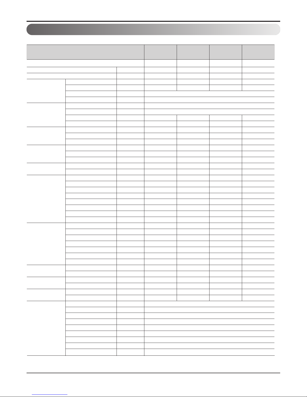
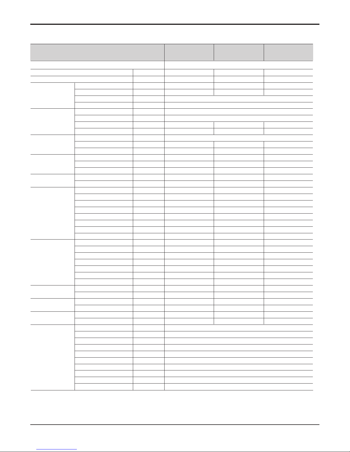
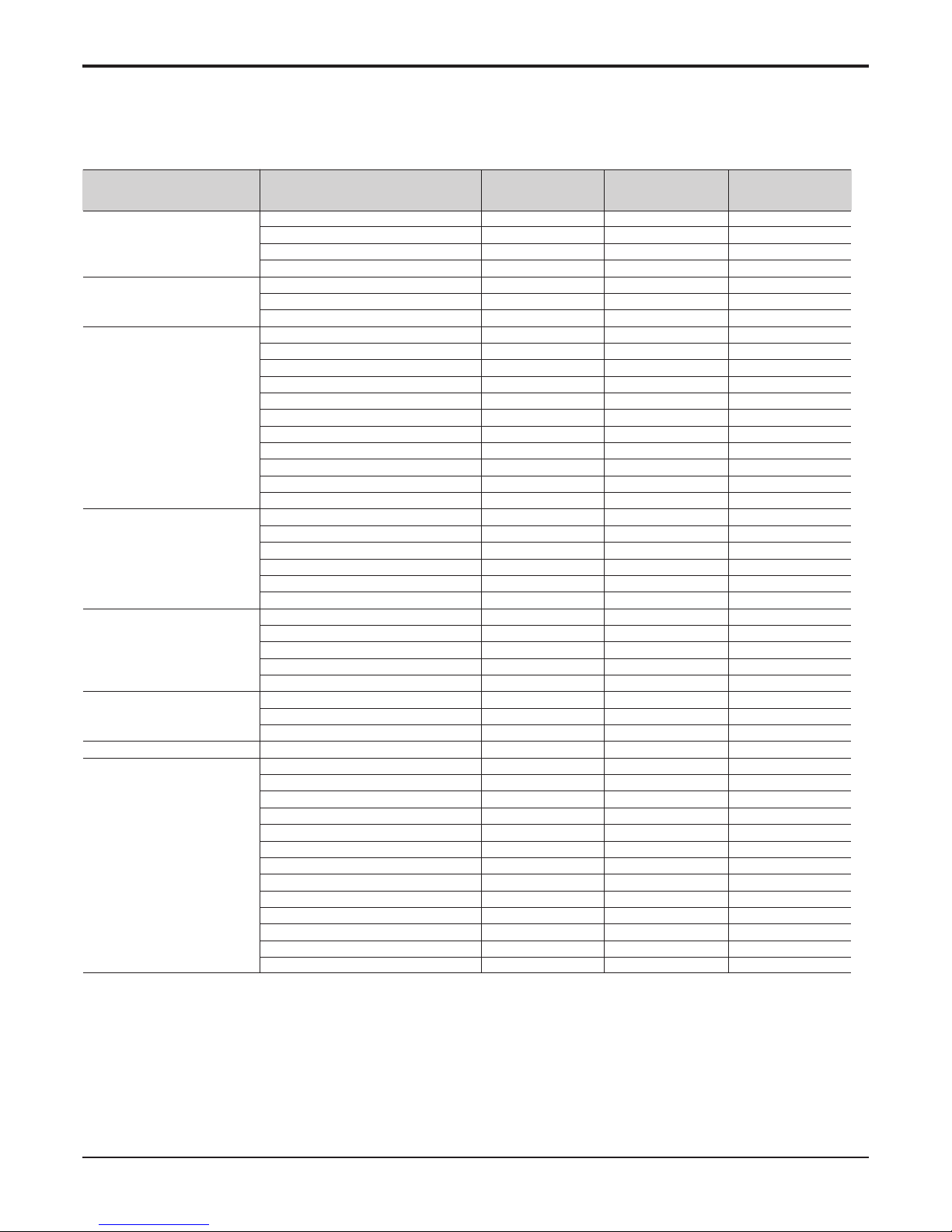
1. Specification
Note : 1. The specification may be subject to change without prior notice for purpose of improvement.
2. * : This information is given as a guideline about the connection of sanitary water tank
3. ** : This specification is data when electric heater is not used.
Nominal Power Input W
Nominal Running Current without Electric Heater A
Operation Range Cooling(Fan coil unit) °C
(Min.~Max.) Cooling(Under floor) °C
Leaving Water
Heating(Fan coil unit or Radiator)
°C
Temperature Heating(Under floor) °C
Pump Type -
Steps of Speed EA
Power Input W
Water Flowrate Limit LPM
Heat Exchanger Type -
Number of Plate EA
Quantity EA
Expansion Vessel Volume liter
Water Pressure(Max.) bar
Water Pressure(Pre) bar
Strainer Mesh Size mm
Material -
Electric Heater Type -
Number of Heating Coil EA
Capacity Combination kW
Operation Heating Steps Step
Power Supply Ø / V / Hz
Rated Current A
Maximum Current(MCA) A
Water Circuit Safety Valve bar
Entering Side Diameter inch
Leaving Side Diameter inch
Manometer Drain Valve / Fill Valve Shut Off Valve Air Vent -
Refrigerant Circuit Gas Side Diameter mm(inch)
Liquid Side Diameter mm(inch)
Dimensions Unit(W x H x D) mm
Packed Unit(W x H x D) mm
Weight Unit kg
(Without water) Packed Unit kg
*Sanitary Water Tank
Type (Field Supply) Heater Capacity kW
Power Supply Ø / V / Hz
Power Supply Type -
Thermal Protector Range °C
Relay Contactor -
ELB A
Sensor Adaptor Diameter mm(inch)
Accessory Kit -
AHNW096A0 AHNW126A0 AHNW146A0 AHNW166A0
(H09SNE) (H12SNE) (H14SNE) (H16SNE)
AHUW096A0 AHUW126A0 AHUW146A0 AHUW166A0
Combination Outdoor Units
Indoor Units
135 205 205 205
0.59 0.89 0.89 0.89
6 ~ 30 6 ~ 30 6 ~ 30 6 ~ 30
16 ~ 30 16 ~ 30 16 ~ 30 16 ~ 30
15~55℃ ( * * 20~55℃)
15~55℃ ( * * 20~55℃)
Canned type for hot water circulation
2 (In Max. / Med. / Min., Min. step is not used)
135 205 205 205
At least 12 At least 12 At least 12 At least 12
Brazed Plate HEX Brazed Plate HEX Brazed Plate HEX Brazed Plate HEX
46 60 60 60
11 1 1
88 8 8
33 3 3
11 1 1
1 x 1 1 x 1 1 x 1 1 x 1
Stainless Steel Stainless Steel Stainless Steel Stainless Steel
Sheath Sheath Sheath Sheath
22 2 2
2 + 2 3 + 3 3 + 3 3 + 3
Automatic Automatic Automatic Automatic
22 2 2
1 / 240 / 50 1 / 240 / 50 1 / 240 / 50 1 / 240 / 50
16.7 25 25 25
21 32 32 32
33 3 3
Male PT 1 Male PT 1 Male PT 1 Male PT 1
Male PT 1 Male PT 1 Male PT 1 Male PT 1
OO O O
OO O O
OO O O
OO O O
15.88 (5/8) 15.88 (5/8) 15.88 (5/8) 15.88 (5/8)
9.52 (3/8) 9.52 (3/8) 9.52 (3/8) 9.52 (3/8)
850 x 490 x 315 850 x 490 x 315 850 x 490 x 315 850 x 490 x 315
1082 x 563 x 375 1082 x 563 x 375 1082 x 563 x 375 1082 x 563 x 375
52 54.5 54.5 54.5
57 61.5 61.5 61.5
Indirect heating(+ Electric heater)
Max. 3
1 / 230 / 50
Separated power source
Max. 90
Needed
40
12.7 (1/2)
LG Supply
Indoor
- 3 -
Copyright ©2014 LG Electronics. Inc. All right reserved.
Only for training and service purposes
LGE Internal Use Only
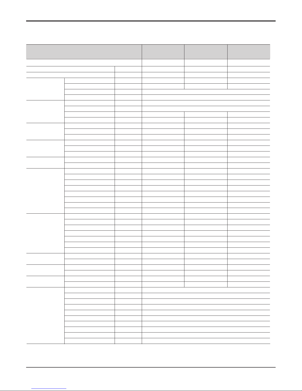
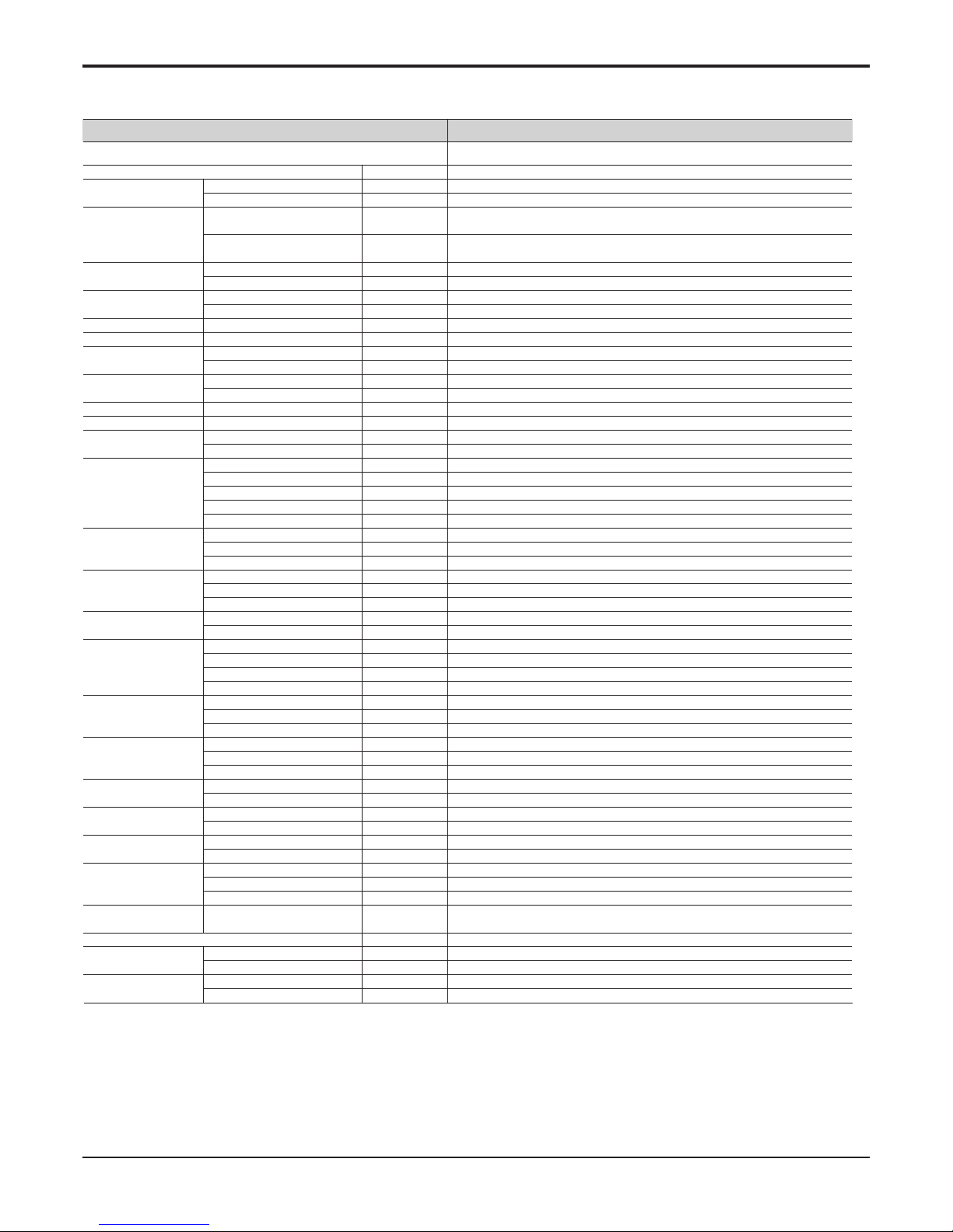
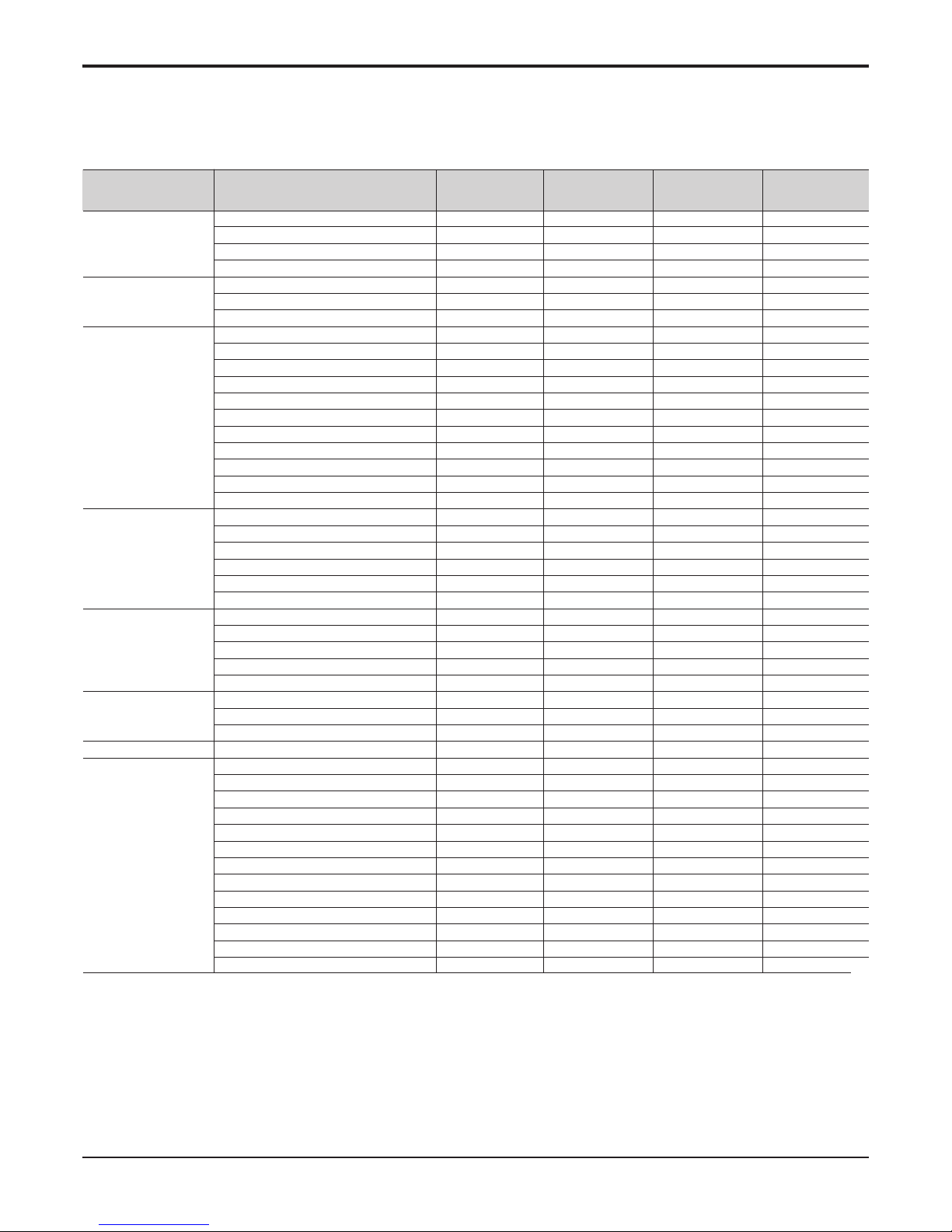
Note : 1. The specification may be subject to change without prior notice for purpose of improvement.
2. * : This information is given as a guideline about the connection of sanitary water tank
3. ** : This specification is data when electric heater is not used.
Nominal Power Input W
Nominal Running Current without Electric Heater A
Operation Range Cooling(Fan coil unit) °C
(Min.~Max.) Cooling(Under floor) °C
Leaving Water
Heating(Fan coil unit or Radiator)
°C
Temperature Heating(Under floor) °C
Pump Type -
Steps of Speed EA
Power Input W
Water Flowrate Limit LPM
Heat Exchanger Type -
Number of Plate EA
Quantity EA
Expansion Vessel Volume liter
Water Pressure(Max.) bar
Water Pressure(Pre) bar
Strainer Mesh Size mm
Material -
Electric Heater Type -
Number of Heating Coil EA
Capacity Combination kW
Operation Heating Steps Step
Power Supply Ø / V / Hz
Rated Current A
Maximum Current(MCA) A
Water Circuit Safety Valve bar
Entering Side Diameter inch
Leaving Side Diameter inch
Manometer Drain Valve / Fill Valve Shut Off Valve Air Vent -
Refrigerant Circuit Gas Side Diameter mm(inch)
Liquid Side Diameter mm(inch)
Dimensions Unit(W x H x D) mm
Packed Unit(W x H x D) mm
Weight Unit kg
(Without water) Packed Unit kg
*Sanitary Water Tank
Type (Field Supply) Heater Capacity kW
Power Supply Ø / V / Hz
Power Supply Type -
Thermal Protector Range °C
Relay Contactor -
ELB A
Sensor Adaptor Diameter mm(inch)
Accessory Kit -
MCCB A
AHNW09606A0 AHNW09A06A0 AHNW09806A0
(NH09SNG) (NH09SNK) (NH09SNP)
AHUW096AN AHUW096AN AHUW096AN
Combination Outdoor Units
Indoor Units
135 135 135
0.59 0.59 0.59~
6~30 6~30 6~30
16~30 16~30 16~30
15~55℃ ( * * 20~55℃)
15~55℃ ( * * 20~55℃)
Canned type for hot water circulation
2 (In Max. / Med. / Min., Min. step is not used)
135 135 135
At least 12 At least 12 At least 12
Brazed Plate HEX Brazed Plate HEX Brazed Plate HEX
46 46 46
11 1
88 8
33 3
11 1
1 x 1 1 x 1 1 x 1
Stainless Steel Stainless Steel Stainless Steel
Sheath Sheath Sheath
23 3
3+3 2+2+2 2+2+2
Automatic Automatic Automatic
22 2
1/230/50 3/220/50 3/380-415/50
27 16 9
30 17 10
33 3
Male PT 1 Male PT 1 Male PT 1
Male PT 1 Male PT 1 Male PT 1
00 0
00 0
00 0
00 0
15.88 (5/8) 15.88 (5/8) 15.88 (5/8)
9.52 (3/8) 9.52 (3/8) 9.52 (3/8)
850 x 490 x 315 850 x 490 x 315 850 x 490 x 315
1082 x 563 x 375 1082 x 563 x 375 1082 x 563 x 375
52 52 52
57 57 57
Indirect heating(+ Electric heater)
Max. 3
1 / 230 / 50
Separated power source
Max. 90
Needed
40
12.7 (1/2)
LG Supply
32
- 4 -
Copyright ©2014 LG Electronics. Inc. All right reserved.
Only for training and service purposes
LGE Internal Use Only
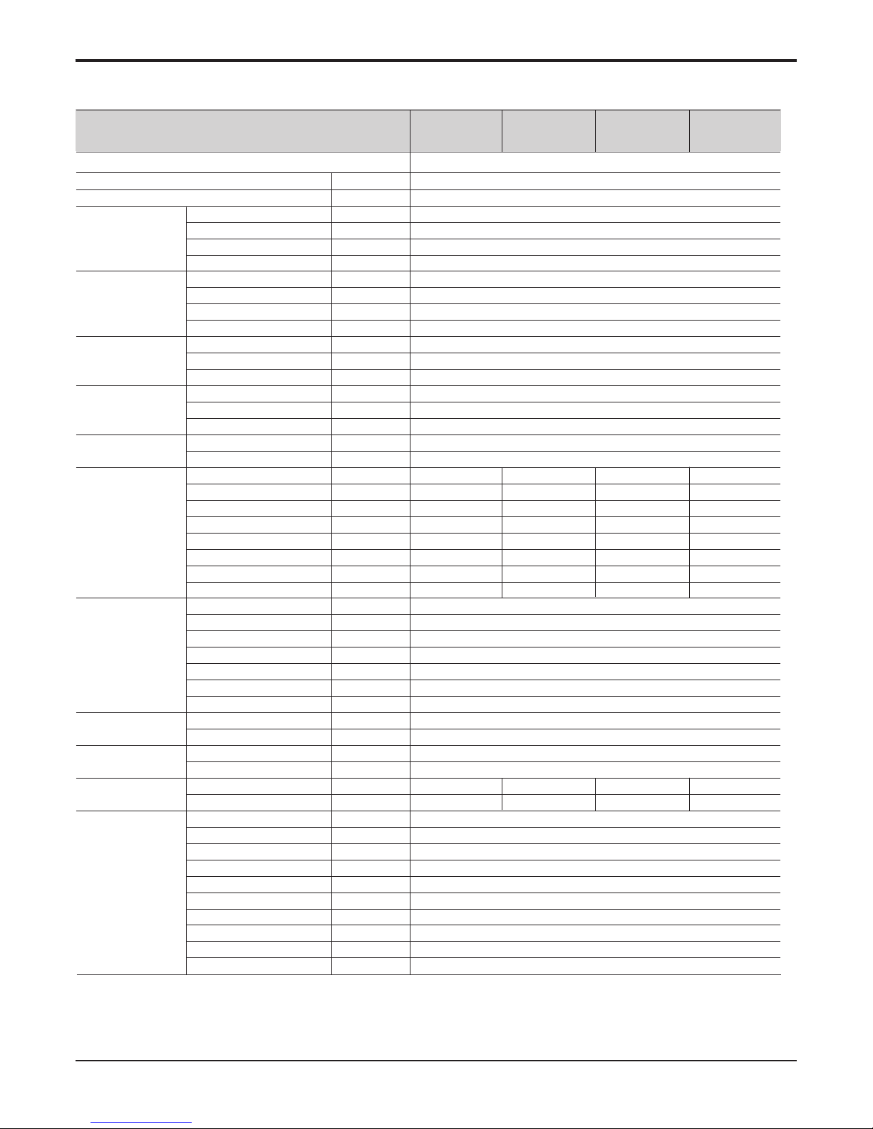
Note : 1. The specification may be subject to change without prior notice
for purpose of improvement.
2. * : This information is given as a guideline about the connection of
sanitary water tank
Nominal Power Input W
Nominal Running Current without Electric Heater A
Operation Range Cooling(Fan coil unit) °C
(Min.~Max.) Cooling(Under floor) °C
Leaving Water
Heating(Fan coil unit or Radiator)
°C
Temperature Heating(Under floor) °C
Pump Type -
Steps of Speed EA
Power Input W
Water Flowrate Limit LPM
Heat Exchanger Type -
Number of Plate EA
Quantity EA
Expansion Vessel Volume liter
Water Pressure(Max.) bar
Water Pressure(Pre) bar
Strainer Mesh Size mm
Material -
Electric Heater Type -
Number of Heating Coil EA
Capacity Combination kW
Operation Heating Steps Step
Power Supply Ø / V / Hz
Rated Current A
Maximum Current(MCA) A
Water Circuit Safety Valve bar
Entering Side Diameter inch
Leaving Side Diameter inch
Manometer Drain Valve / Fill Valve Shut Off Valve Air Vent -
Refrigerant Circuit Gas Side Diameter mm(inch)
Liquid Side Diameter mm(inch)
Dimensions Unit(W x H x D) mm
Packed Unit(W x H x D) mm
Weight Unit kg
(Without water) Packed Unit kg
*Sanitary Water Tank
Type (Field Supply) Heater Capacity kW
Power Supply Ø / V / Hz
Power Supply Type -
Thermal Protector Range °C
Relay Contactor -
ELB A
Sensor Adaptor Diameter mm(inch)
Accessory Kit -
MCCB A
AHNW09604A1 AHNW09606A1 AHNW09A06A1 AHNW09806A1
AHUW096A1
Combination Outdoor Units
Indoor Units
135
0.59
6 ~ 30
16 ~ 30
15~55℃ ( * * 20~55℃)
15~55℃ ( * * 20~55℃)
Canned type for hot water circulation
2(In Max. / Med. / Min., Min. step is not used)
135
At least 12
Brazed Plate HEX
54
1
8
3
1
1 X 1
Stainless steel
Sheath Sheath Sheath Sheath
22 33
2+2 3+3 2+2+2 2+2+2
Automatic Automatic Automatic Automatic
22 22
1/240/50 1/240/50 3/220/50 3/380~415/50
16.7 26 16 9
21 33 20 12
3
Male PT 1
Male PT 1
O
O
O
O
15.88 (5/8)
9.52 (3/8)
850 X 490 X 315
1082 X 563 X 375
48 48 52 52
55 55 59 59
Indirect heating(+Electric heater)
Max. 3
1/230/50
Separated Power Source
Max. 90
Needed
40
12.7 (1/2)
LG Supply
32
- 5 -
Copyright ©2014 LG Electronics. Inc. All right reserved.
Only for training and service purposes
LGE Internal Use Only
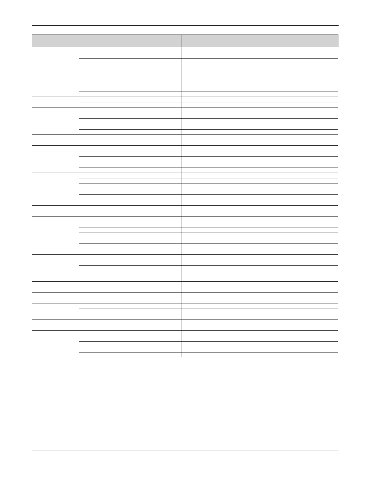
Note : 1. The specification may be subject to change without prior notice
for purpose of improvement.
2. * : This information is given as a guideline about the connection of
sanitary water tank
Nominal Power Input W
Nominal Running Current without Electric Heater A
Operation Range Cooling(Fan coil unit) °C
(Min.~Max.) Cooling(Under floor) °C
Leaving Water
Heating(Fan coil unit or Radiator)
°C
Temperature Heating(Under floor) °C
Pump Type -
Steps of Speed EA
Power Input W
Water Flowrate Limit LPM
Heat Exchanger Type -
Number of Plate EA
Quantity EA
Expansion Vessel Volume liter
Water Pressure(Max.) bar
Water Pressure(Pre) bar
Strainer Mesh Size mm
Material -
Electric Heater Type -
Number of Heating Coil EA
Capacity Combination kW
Operation Heating Steps Step
Power Supply Ø / V / Hz
Rated Current A
Maximum Current(MCA) A
Water Circuit Safety Valve bar
Entering Side Diameter inch
Leaving Side Diameter inch
Manometer Drain Valve / Fill Valve Shut Off Valve Air Vent -
Refrigerant Circuit Gas Side Diameter mm(inch)
Liquid Side Diameter mm(inch)
Dimensions Unit(W x H x D) mm
Packed Unit(W x H x D) mm
Weight Unit kg
(Without water) Packed Unit kg
*Sanitary Water Tank
Type (Field Supply) Heater Capacity kW
Power Supply Ø / V / Hz
Power Supply Type -
Thermal Protector Range °C
Relay Contactor -
ELB A
Sensor Adaptor Diameter mm(inch)
Accessory Kit -
MCCB A
AHNW16606A1 AHNW16A06A1 AHNW16806A1
AHUW128A1 / AHUW148A1 / AHUW168A1
Combination Outdoor Units
Indoor Units
205 205 205
0.89 0.89 0.89
6 ~ 30 6 ~ 30 6 ~ 30
16 ~ 30 16 ~ 30 16 ~ 30
15~55℃ ( * * 20~55℃)
15~55℃ ( * * 20~55℃)
Canned type for hot water circulation
2(In Max. / Med. / Min., Min. step is not used)
205 205 205
At least 15 At least 15 At least 15
Brazed Plate HEX
76 76 76
111
888
333
111
1 X 1 1 X 1 1 X 1
Stainless steel Stainless steel Stainless steel
Sheath Sheath Sheath
233
3+3 2+2+2 2+2+2
Automatic Automatic Automatic
222
1/240/50 3/220/50 3/380~415/50
25 16 9
32 20 12
333
Male PT 1 Male PT 1 Male PT 1
Male PT 1 Male PT 1 Male PT 1
OOO
OOO
OOO
OOO
15.88 (5/8) 15.88 (5/8) 15.88 (5/8)
9.52 (3/8) 9.52 (3/8) 9.52 (3/8)
850 X 490 X 315 850 X 490 X 315 850 X 490 X 315
1082 X 563 X 375 1082 X 563 X 375 1082 X 563 X 375
52 52 52
59 59 59
Indirect heating(+Electric heater)
Max. 3
1/230/50
Separated Power Source
Max. 90
Needed
40
12.7 (1/2)
LG Supply

- 6 -
Copyright ©2014 LG Electronics. Inc. All right reserved.
Only for training and service purposes
LGE Internal Use Only
Note :
1. Capacities and power inputs are based on the following conditions:
* : Cooling conditions - Indoor Water Temperature 23°C/18°C; Outdoor Air Temperature 35°CDB
Heating conditions - Indoor Water Temperature 30°C/35°C; Outdoor Air Temperature 7°CDB/6°CWB
Standard piping length 7.5m
** : Cooling conditions - Indoor Water Temperature 12°C/7°C; Outdoor Air Temperature 35°CDB
Heating conditions - Indoor Water Temperature 40°C/45°C; Outdoor Air Temperature 7°CDB/6°CWB
Standard piping length 7.5m
2. Wiring cable size must comply with the applicable local and national code.
3. The specification may be subject to change without prior notice for purpose of improvement.
Power Supply Ø / V / Hz
Maximum Running Cooling A
Current Heating A
Wiring Connections
For Power Supply
Number of wires
(Included Earth)
For Connection with
Number of wires
Indoor Unit (Included Earth)
* Capacity Cooling(Under floor) kW
Heating(Under floor) kW
* Power Input Cooling(Under floor) kW
Heating(Under floor) kW
* EER Cooling(Under floor) W/W
* COP Heating(Under floor) W/W
** Capacity Cooling(Fan coil unit) kW
Heating(Fan coil unit or Radiator)
kW
** Power Input Cooling(Fan coil unit) kW
Heating(Fan coil unit or Radiator)
kW
** EER Cooling(Fan coil unit) W/W
** COP
Heating(Fan coil unit or Radiator)
W/W
Operation Range(Min.~Max.)
Cooling °C DB
Outdoor Temperature
Heating °C DB
Compressor Type -
Model Quantity EA
Displacement cm3/Rev.
Capacity kW
Compressor Motor Type -
Quantity EA
Rated Output W
Refrigerant Type -
Charge g(oz)
Control -
Refrigerant Oil Type -
Charged Volume cc
Heat Exchanger Quantity EA
Rows EA
Columns EA
FPI Fins/inch
Fan Type -
Quantity EA
Air Flow Rate CMM(l/s)
Fan Motor Model -
Quantity EA
Output W
Sound Pressure Cooling dB(A)+3
Level Heating dB(A)+3
Liquid Piping Type Connection Outer Diameter mm(inch)
Gas Piping Type Connection Outer Diameter mm(inch)
Piping Length Minimum m
(Outdoor Unit ~ Standard m
Indoor Unit) Maximum m
Height Difference
Maximum m
(Outdoor Unit ~ Indoor Unit)
Additional Refrigerant Charge
g/m
Dimensions Unit(W x H x D) mm
Packed Unit(W x H x D) mm
Weight Unit kg
Packed Unit kg
AHUW096A0(H09SNE) AHUW126A0(H12SNE) AHUW146A0(H14SNE) AHUW166A0(H16SNE)
AHNW096A0 AHNW126A0 AHNW146A0 AHNW166A0
Outdoor Units
Combination Indoor Units
1/220-240/50 1/220-240/50 1/220-240/50 1/220-240/50
24 32 32 32
24 32 32 32
33 3 3
44 4 4
8.60 14.0 14.0 14.0
9.00 12.0 14.0 16.0
2.70 4.40 4.40 4.40
2.20 2.67 3.17 3.80
3.19 3.18 3.18 3.18
4.10 4.50 4.42 4.20
5.83 9.50 9.50 9.50
7.49 9.99 11.7 13.3
2.24 3.65 3.65 3.65
2.30 2.79 3.41 4.01
2.60 2.60 2.60 2.60
3.26 3.58 3.43 3.32
5~48 5~48 5~48 5~48
-20~30 -20~30 -20~30 -20~30
Hermetic Motor Hermetic Motor Hermetic Motor Hermetic Motor
5KD240XAE21 5JD420XAD22 5JD420XAD22 5JD420XAD22
11 1 1
24 42.4 42.4 42.4
7.28 13.4 (at 57.5Hz) 13.4 (at 57.5Hz) 13.4 (at 57.5Hz)
Brushless Brushless Brushless Brushless
11 1 1
1,700 3,000 3,000 3,000
R410A R410A R410A R410A
1,900(67.02) 3,000(105.8) 3,000(105.8) 3,000(105.8)
Electronic Expansion Valve Electronic Expansion Valve Electronic Expansion Valve Electronic Expansion Valve
FV50S FV50S FV50S FV50S
900 1300 1300 1300
12 2 2
22 2 2
36 32 32 32
18 17 17 17
Propeller Propeller Propeller Propeller
12 2 2
58(967) 60(1,000) 60(1,000) 60(1,000)
SIC-72FW-F1124-3 SIC-72FW-F1124-3 SIC-72FW-F1124-3 SIC-72FW-F1124-3
12 2 2
124 124 124 124
51 55 55 55
53 57 57 57
Flare Flare Flare Flare
9.52(3/8) 9.52(3/8) 9.52(3/8) 9.52(3/8)
Flare Flare Flare Flare
15.88(5/8) 15.88(5/8) 15.88(5/8) 15.88(5/8)
33 3 3
7.5 7.5 7.5 7.5
50 50 50 50
30 30 30 30
30 60 60 60
870 x 800 x 320 950 x 1,355 x 330 950 x 1,355 x 330 950 x 1,355 x 330
1,022 x 870 x 437 1,140 x 1462 x 461 1,140 x 1462 x 461 1,140 x 1462 x 461
56 105 105 105
61 116 116 116
Outdoor
- 7 -
Copyright ©2014 LG Electronics. Inc. All right reserved.
Only for training and service purposes
LGE Internal Use Only
Note :
1. Capacities and power inputs are based on the following conditions:
* : Cooling conditions - Indoor Water Temperature 23°C/18°C; Outdoor Air Temperature 35°CDB
Heating conditions - Indoor Water Temperature 30°C/35°C; Outdoor Air Temperature 7°CDB/6°CWB
Standard piping length 7.5m
** : Cooling conditions - Indoor Water Temperature 12°C/7°C; Outdoor Air Temperature 35°CDB
Heating conditions - Indoor Water Temperature 40°C/45°C; Outdoor Air Temperature 7°CDB/6°CWB
Standard piping length 7.5m
2. Wiring cable size must comply with the applicable local and national code.
3. The specification may be subject to change without prior notice for purpose of improvement.
Power Supply Ø / V / Hz
Maximum Running Cooling A
Current Heating A
Wiring Connections
For Power Supply
Number of wires
(Included Earth)
For Connection with
Number of wires
Indoor Unit (Included Earth)
* Capacity Cooling(Under floor) kW
Heating(Under floor) kW
* Power Input Cooling(Under floor) kW
Heating(Under floor) kW
* EER Cooling(Under floor) W/W
* COP Heating(Under floor) W/W
** Capacity Cooling(Fan coil unit) kW
Heating(Fan coil unit or Radiator)
kW
** Power Input Cooling(Fan coil unit) kW
Heating(Fan coil unit or Radiator)
kW
** EER Cooling(Fan coil unit) W/W
** COP
Heating(Fan coil unit or Radiator)
W/W
Operation Range(Min.~Max.)
Cooling °C DB
Outdoor Temperature
Heating °C DB
Compressor Type -
Model Quantity EA
Displacement cm3/Rev.
Capacity kW
Compressor Motor Type -
Quantity EA
Rated Output W
Refrigerant Type -
Charge g(oz)
Control -
Refrigerant Oil Type -
Charged Volume cc
Heat Exchanger Quantity EA
Rows EA
Columns EA
FPI Fins/inch
Fan Type -
Quantity EA
Air Flow Rate CMM(l/s)
Fan Motor Model -
Quantity EA
Output W
Sound Pressure Cooling dB(A)+3
Level Heating dB(A)+3
Liquid Piping Type Connection Outer Diameter mm(inch)
Gas Piping Type Connection Outer Diameter mm(inch)
Piping Length Minimum m
(Outdoor Unit ~ Standard m
Indoor Unit) Maximum m
Height Difference
Maximum m
(Outdoor Unit ~ Indoor Unit)
Additional Refrigerant Charge
g/m
Dimensions Unit(W x H x D) mm
Packed Unit(W x H x D) mm
Weight Unit kg
Packed Unit kg
AHUW096AN (UH09SNG)
AHNW09606A0/ AHNW09A06A0/ AHNW09806A0
Outdoor Units
Combination Indoor Units
1/220-240/50
24
24
3
4
8.60
9.00
2.70
2.22
3.19
4.05
5.83
7.49
2.24
2.30
2.60
3.26
5 ~ 48
-20 ~ 30
Hermetic Motor
5KD240XAE21
1
24
7.28
Brushless
1
1,700
R410A
1,900(67.02)
Electronic Expansion Valve
FV50S
900
1
2
36
18
Propeller
1
58(967)
SIC-72FW-F1124-3
1
124
51
53
Flare
9.52(3/8)
Flare
15.88(5/8)
3
7.5
50
30
30
870 x 800 x 320
1,022 x 870 x 437
56
61

- 8 -
Copyright ©2014 LG Electronics. Inc. All right reserved.
Only for training and service purposes
LGE Internal Use Only
Note :
1. Capacities and power inputs are based on the following conditions:
* : Cooling conditions - Indoor Water Temperature 23°C/18°C; Outdoor Air Temperature 35°CDB/24°CWB
Heating conditions - Indoor Water Temperature 30°C/35°C; Outdoor Air Temperature 7°CDB/6°CWB
Standard piping length 7.5m
2. Wiring cable size must comply with the applicable local and national code.
3. The specification may be subject to change without prior notice for purpose of improvement.
Power Supply Ø / V / Hz
Maximum Running Cooling A
Current Heating A
Wiring Connections
For Power Supply
Number of wires
(Included Earth)
For Connection with
Number of wires
Indoor Unit (Included Earth)
* Capacity Cooling(A35/W18) kW
Heating(A7W35) kW
* Power Input Cooling(A35/W18) kW
Heating(A7W35) kW
* EER Cooling(A35/W18) W/W
COP Heating(A7W35) W/W
Heating(A2W35) W/W
Heating(A10W35) W/W
Heating(A-7W35) W/W
Operation Range(Min.~Max.)
Cooling °C DB
Outdoor Temperature
Heating °C DB
Compressor Type -
Model -
Quantity EA
Displacement cm3/Rev.
Capacity kW
Compressor Motor Type -
Quantity EA
Rated Output W
Refrigerant Type -
Charge g(oz)
Control Refrigerant Oil Type -
Charged Volume cc
Heat Exchanger Quantity EA
Rows EA
Columns EA
FPI Fins/inch
Fan Type -
Quantity EA
Air Flow Rate CMM(l/s)
Fan Motor Model -
Quantity EA
Output W
Sound Pressure Cooling dB(A)±3
Level Heating dB(A)±3
Liquid Piping Type Connection Outer Diameter mm(inch)
Gas Piping Type Connection Outer Diameter mm(inch)
Piping Length Minimum m
(Outdoor Unit ~ Standard m
Indoor Unit) Maximum m
Height Difference
Maximum m
(Outdoor Unit ~ Indoor Unit)
Additional Refrigerant Charge
g/m
Dimensions Unit(W x H x D) mm
Packed Unit(W x H x D) mm
Weight Unit kg
Packed Unit kg
AHUW096A1
(HU091 U41)
AHUW128A1
(HU123 U31)
Outdoor Units
1 / 220-240 / 50 3/380-415/50
24 32
24 32
35
44
8.90 14.6
9.00 12.0
2.70 4.02
2.19 2.67
3.19 3.60
4.10 4.49
3.15 3.37
4.50 4.37
2.72 2.63
5~48 5~48
-20~30 -20~30
Hermetic Motor Hermetic Motor
GJT240DAA GPT425DAA
11
24 42.4
7.28 12.05 (at 60Hz)
Brushless Brushless
11
1,700 4,000
R410A R410A
1,900(67.0) 2,980(105.1)
Electronic Expansion Valve Electronic Expansion Valve
FV50S FV50S
900 1,300
12
22
36 32
18 17
Propeller Propeller
12
58(967) 60(1,000)
SIC-72FW-F1124-3 SIC-72FW-F1124-3
12
124 124
52 54
52 53
Flare Flare
9.52(3/8) 9.52(3/8)
Flare Flare
15.88(5/8) 15.88(5/8)
33
7.5 7.5
50 50
30 30
30 50
950 x 833 x 400 950 x 1,380 x 330
1,140 x 900 x 461 1,140 x 1,462 x 461
64 105
69 116
- 9 -
Copyright ©2014 LG Electronics. Inc. All right reserved.
Only for training and service purposes
LGE Internal Use Only
Note :
1. Capacities and power inputs are based on the following conditions:
* : Cooling conditions - Indoor Water Temperature 23°C/18°C; Outdoor Air Temperature 35°CDB/24°CWB
Heating conditions - Indoor Water Temperature 30°C/35°C; Outdoor Air Temperature 7°CDB/6°CWB
Standard piping length 7.5m
2. Wiring cable size must comply with the applicable local and national code.
3. The specification may be subject to change without prior notice for purpose of improvement.
Power Supply Ø / V / Hz
Maximum Running Cooling A
Current Heating A
Wiring Connections
For Power Supply
Number of wires
(Included Earth)
For Connection with
Number of wires
Indoor Unit (Included Earth)
* Capacity Cooling(A35/W18) kW
Heating(A7W35) kW
* Power Input Cooling(A35/W18) kW
Heating(A7W35) kW
* EER Cooling(A35/W18) W/W
COP Heating(A7W35) W/W
Heating(A2W35) W/W
Heating(A10W35) W/W
Heating(A-7W35) W/W
Operation Range(Min.~Max.)
Cooling °C DB
Outdoor Temperature
Heating °C DB
Compressor Type -
Model -
Quantity EA
Displacement cm3/Rev.
Capacity kW
Compressor Motor Type -
Quantity EA
Rated Output W
Refrigerant Type -
Charge g(oz)
Control Refrigerant Oil Type -
Charged Volume cc
Heat Exchanger Quantity EA
Rows EA
Columns EA
FPI Fins/inch
Fan Type -
Quantity EA
Air Flow Rate CMM(l/s)
Fan Motor Model -
Quantity EA
Output W
Sound Pressure Cooling dB(A)±3
Level Heating dB(A)±3
Liquid Piping Type Connection Outer Diameter mm(inch)
Gas Piping Type Connection Outer Diameter mm(inch)
Piping Length Minimum m
(Outdoor Unit ~ Standard m
Indoor Unit) Maximum m
Height Difference
Maximum m
(Outdoor Unit ~ Indoor Unit)
Additional Refrigerant Charge
g/m
Dimensions Unit(W x H x D) mm
Packed Unit(W x H x D) mm
Weight Unit kg
Packed Unit kg
AHUW148A1
(HU143 U31)
AHUW168A1
(HU163 U31)
Outdoor Units
3/380-415/50 3/380-415/50
32 32
32 32
55
44
15.5 16.8
14.5 16.0
4.65 5.09
3.38 3.81
3.33 3.33
4.29 4.20
3.33 3.20
4.21 4.16
2.77 2.63
5~48 5~48
-20~30 -20~30
Hermetic Motor Hermetic Motor
GPT425DAA GPT425DAA
11
42.4 42.4
12.05 (at 60Hz) 12.05 (at 60Hz)
Brushless Brushless
11
4,000 4,000
R410A R410A
2,980(105.1) 2,980(105.1)
Electronic Expansion Valve Electronic Expansion Valve
FV50S FV50S
1,300 1,300
22
22
32 32
17 17
Propeller Propeller
22
60(1,000) 60(1,000)
SIC-72FW-F1124-3 SIC-72FW-F1124-3
22
124 124
54 54
53 53
Flare Flare
9.52(3/8) 9.52(3/8)
Flare Flare
15.88(5/8) 15.88(5/8)
33
7.5 7.5
50 50
30 30
50 50
950 x 1,380 x 330 950 x 1,380 x 330
1,140 x 1,462 x 461 1,140 x 1,462 x 461
105 105
116 116
- 10 -
Copyright ©2014 LG Electronics. Inc. All right reserved.
Only for training and service purposes
LGE Internal Use Only
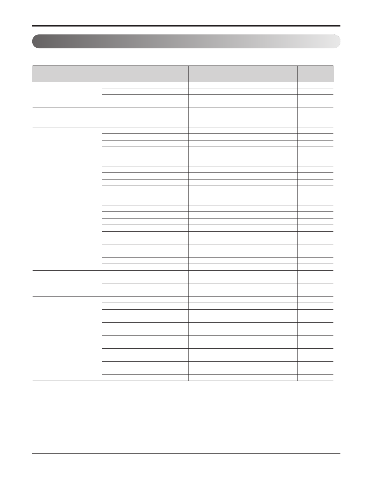
2. Function Table
Indoor
Installation Drain pump
E.S.P. control
Electric heater(operation)
High ceiling operation
Reliability Hot start
Self diagnosis
Soft dry operation
Convenience Auto changeover
Auto cleaning
Auto operation(artificial intelligence)
Auto restart operation
Child lock
Forced operation
Group control
Sleep mode
Timer(on/off)
Timer(weekly)
Two thermistor control
Individual control
Standard wired remote controller(control panel)
Deluxe wired remote controller
Simple wired remote controller
Wired remote controller(for hotel use)
Wireless remote controller(simple)
Wireless LCD remote control
CAC network function General central controller (Non LGAP)
Dry contact
Network Soluation(LGAP)
PDI(power distribution indicator)
PI 485
Special function kit Zone control
CTIE
Electro thermostat
Others Remote room temperature sensor (TH8)
AWHP Anti-Condensation on floor (cooling)
Water Pump ON / OFF Control
Flow Switch Control
Thermostat Interface (230V AC)
Thermostat Interface (24V AC)
Sanitary Tank Heating
Solar-Thermal Interface with Sanitary Tank
PHEX Anti-Freezing Control
Water Pump Forced Operation
Autosetting according to Ambient Temperature
Silent Operation
Anti-overheating of Water Pipe
Emergency Operation
----
----
OOOO
----
----
OOOO
----
----
----
---OOOO
OOOO
----
----
---OOOO
OOOO
---OOOO
----
----
----
----
----
----
PQDSA PQDSA PQDSA PQDSA
OOOO
----
----
----
----
----
PQRSTA0 PQRSTA0 PQRSTA0 PQRSTA0
OOOO
OOOO
OOOO
OOOO
OOOO
OOOO
OOOO
OOOO
OOOO
OOOO
OOOO
OOOO
OOOO
Category Function
AHNW096A0
(H09SNE)
AHNW126A0
(H12SNE)
AHNW146A0
(H14SNE)
AHNW166A0
(H16SNE)
Notes
O : Applied, X : Not applied, – : No relation
* TH8 : Refer to 'Chapter 8. Piping Diagram' of 'Part 2. Indoor Unit (Hydro kit)'
* Accessory: Installed at field, ordered and purchased separately by the corresponding model name, supplied with separate
package.
- 11 -
Copyright ©2014 LG Electronics. Inc. All right reserved.
Only for training and service purposes
LGE Internal Use Only
Installation Drain pump
E.S.P. control
Electric heater(operation)
High ceiling operation
Reliability Hot start
Self diagnosis
Soft dry operation
Convenience Auto changeover
Auto cleaning
Auto operation(artificial intelligence)
Auto restart operation
Child lock
Forced operation
Group control
Sleep mode
Timer(on/off)
Timer(weekly)
Two thermistor control
Individual control
Standard wired remote controller(control panel)
Deluxe wired remote controller
Simple wired remote controller
Wired remote controller(for hotel use)
Wireless remote controller(simple)
Wireless LCD remote control
CAC network function General central controller (Non LGAP)
Dry contact
Network Soluation(LGAP)
PDI(power distribution indicator)
PI 485
Special function kit Zone control
CTIE
Electro thermostat
Others Remote room temperature sensor (TH8)
AWHP Anti-Condensation on floor (cooling)
Water Pump ON / OFF Control
Flow Switch Control
Thermostat Interface (230V AC)
Thermostat Interface (24V AC)
Sanitary Tank Heating
Solar-Thermal Interface with Sanitary Tank
PHEX Anti-Freezing Control
Water Pump Forced Operation
Autosetting according to Ambient Temperature
Silent Operation
Anti-overheating of Water Pipe
Emergency Operation
---
---
OOO
---
---
OOO
---
---
---
--OOO
OOO
---
---
--OOO
OOO
--OOO
---
---
---
---
---
---
PQDSA PQDSA PQDSA
OOO
---
---
---
---
---
PQRSTA0 PQRSTA0 PQRSTA0
OOO
OOO
OOO
OOO
OOO
OOO
OOO
OOO
OOO
OOO
OOO
OOO
OOO
Category Function
AHNW09606A0
(NH09SNG)
AHNW09A06A0
(NH09SNK)
AHNW09806A0
(NH09SNP)
Notes
O : Applied, X : Not applied, – : No relation
* TH8 : Refer to 'Chapter 8. Piping Diagram' of 'Part 2. Indoor Unit (Hydro kit)'
* Accessory: Installed at field, ordered and purchased separately by the corresponding model mane, supplied with separate
package.
- 12 -
Copyright ©2014 LG Electronics. Inc. All right reserved.
Only for training and service purposes
LGE Internal Use Only
Installation Drain pump
E.S.P. control
Electric heater(operation)
High ceiling operation
Reliability Hot start
Self diagnosis
Soft dry operation
Convenience Auto changeover
Auto cleaning
Auto operation(artificial intelligence)
Auto restart operation
Child lock
Forced operation
Group control
Sleep mode
Timer(on/off)
Timer(weekly)
Two thermistor control
Individual control
Standard wired remote controller(control panel)
Deluxe wired remote controller
Simple wired remote controller
Wired remote controller(for hotel use)
Wireless remote controller(simple)
Wireless LCD remote control
CAC network function General central controller (Non LGAP)
Dry contact
Network Soluation(LGAP)
PDI(power distribution indicator)
PI 485
Special function kit Zone control
CTIE
Electro thermostat
Others Remote room temperature sensor (TH8)
AWHP Anti-Condensation on floor (cooling)
Water Pump ON / OFF Control
Flow Switch Control
Thermostat Interface (230V AC)
Thermostat Interface (24V AC)
Sanitary Tank Heating
Solar-Thermal Interface with Sanitary Tank
PHEX Anti-Freezing Control
Water Pump Forced Operation
Autosetting according to Ambient Temperature
Silent Operation
Anti-overheating of Water Pipe
Emergency Operation
--- -
--- -
OOO O
--- -
--- -
OOO O
--- -
--- -
--- -
--- OOO O
OOO O
--- -
--- -
--- OOO O
OOO O
--- OOO O
--- -
--- -
--- -
--- -
--- -
--- -
PQDSA PQDSA PQDSA PQDSA
OOO O
--- -
--- -
--- -
--- -
--- -
PQRSTA0 PQRSTA0 PQRSTA0 PQRSTA0
OOO O
OOO O
OOO O
OOO O
OOO O
OOO O
OOO O
OOO O
OOO O
OOO O
OOO O
OOO O
OOO O
Category Function
AHNW09604A1 AHNW09606A1 AHNW09A06A1 AHNW09806A1
Notes
O : Applied, X : Not applied, – : No relation
* TH8 : Refer to 'Chapter 8. Piping Diagram' of 'Part 2. Indoor Unit (Hydro kit)'
* Accessory: Installed at field, ordered and purchased separately by the corresponding model mane, supplied with separate
package.
 Loading...