

LG MFL65003102 Installation Manual

INSTALLATION MANUAL
AIR CONDITIONER
• Please read this installation manual completely before installing the product.
• Installation work must be performed in accordance with the national wiring
standards by authorized personnel only.
• Please retain this installation manual for future reference after reading
it thoroughly.
P/NO : MFL65003102
www.lg.com
TYPE: Vertical Air Handling Unit
ENGLISH FRANÇAIS ESPAÑOL
2 Vertical Air Handling Unit

Installation Manual 3
ENGLISH
Vertical Air Handling Unit Installation Manual
TABLE OF CONTENTS
❏ Four type "A" screws
❏ Pipes: Gas side
Liquid side (Refer to
Product Data)
❏ Insulation materials
❏ Additional drain pipe
❏ Level gauge
❏ Screw driver
❏ Electric drill
❏ Hole core drill
❏ Hexagonal wrench
❏ Gas-leak detector
❏ Vacuum pump
❏ Gauge manifold
❏ Owner's manual
❏ Thermometer
❏ Electric Heater installation
manual
Features ......................................4
Accessories ..............................4
Duct Connection Dimensions ..5
Safety Precautions....................6
Installation ..................................8
Selection of the best location ...8
Upflow Installation ....................9
Duct work................................10
Horizontal-left Installation .......11
Connecting Pipes to the Indoor
Unit ..........................................12
Preparation of Piping..............12
Insulation.................................15
Condensate Drain ..................16
Wiring Connection..................18
Installation of Wired Remote
Controller ................................20
Name and function of wired
remote controller(Accessory).22
Name and function of wireless
remote controller(Accessory).23
Electric Heater ........................24
Dip Switch Setting of Indoor unit
PCB.........................................25
Group Control Setting ............26
How to Set E.S.P? ...................30
Product Data ............................32
External Static Pressure & Air
Flow.........................................32
Minimum airflow by heater
capacity...................................33
Electric Heater Static pressure
drop factors.............................33
Air Filter (Field supply) Static
pressure drop factors .............34
Installation Requirements
Required Parts Required Tools
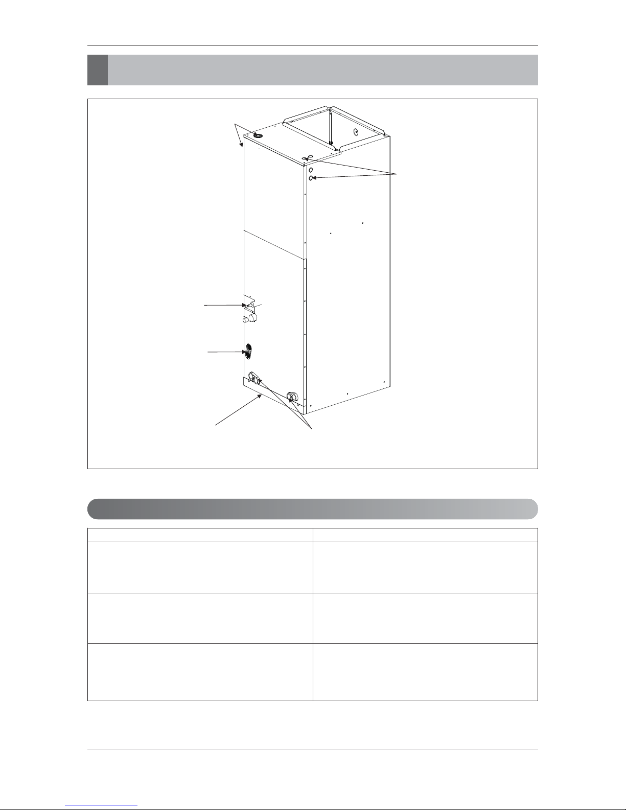
Wiring knockouts
for conduit
Wiring knockouts
for conduit
Refrigerant
connections
Drain connections
for horizontal
application
Filter access
Drain connections for
upflow application
Feature
Accessories
Accessory Model Name
Wired remote controller
PQRCVSL0 (Black Color)
PQRCVSL0QW (White Color)
Wireless remote controller
PQWRCDF0 (Heat pump)
PQWRHDF0 (Cooling only)
Electric heater
ANEH053B1
ANEH103B2
ANEH153B2
ANEH203B2
4 Vertical Air Handling Unit
Features
ENGLISH
Feature
Installation Manual 5
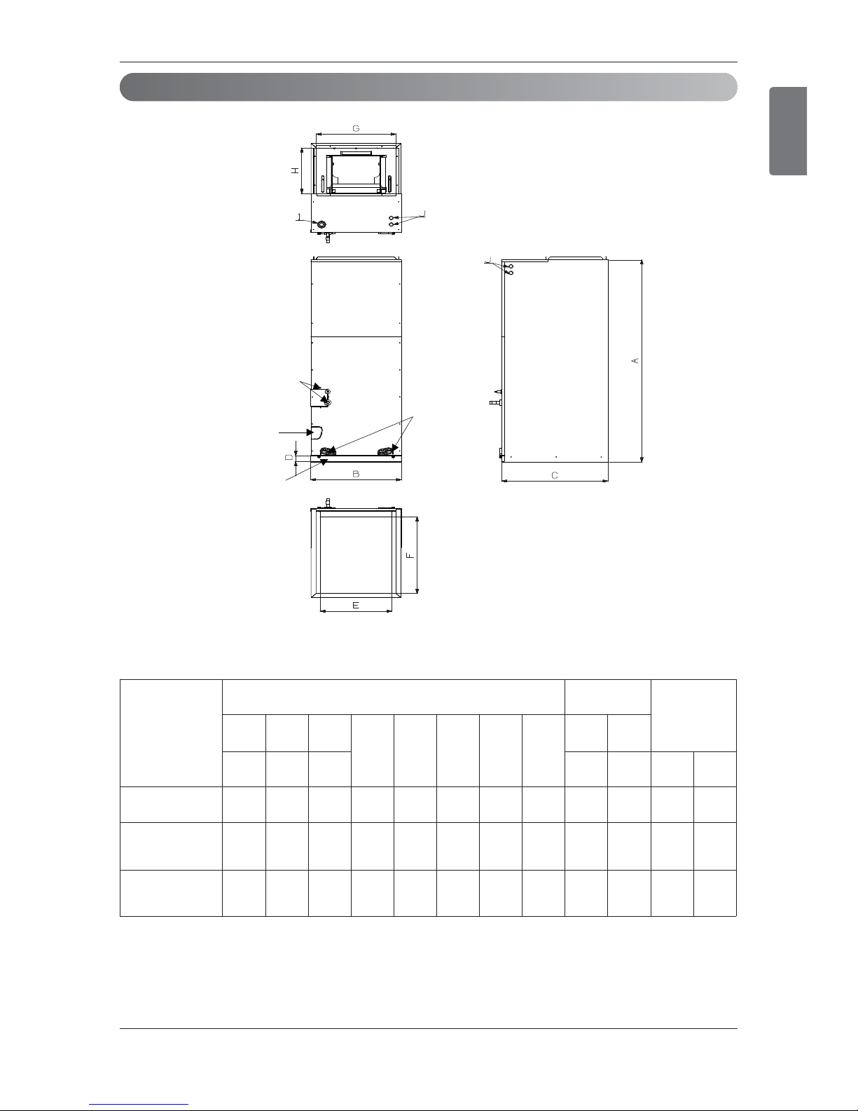
Duct Connection Dimensions
<Top>
<Front>
<Bottom>
<Side-right>
Refrigerant
connections
Drain connections
for horizontal
application
Drain
connections
for upflow
application
Air filter cover
(Unit: inch(mm))
Capacity
(kBtu/h (RT))
Dimensions
Wiring
Knock out
Refrigerant
Connections
Pipe size
A B C
D E F G H
I J
Height Width Depth Power
Commu
nication
Liquid Gas
18(1.5)
48-5/8
(1236)18(457)
21-3/8
(540)
1-9/16
(40)
17-1/2
(445)20(530)17(432)
12-1/8
(308)
1-11/16
(43)
7/8
(22)
1/4
(6.35)
1/2
(12.7)
24(2.0)
30(2.5)
36(3.0)
48-5/8
(1236)18(457)
21-3/8
(540)
1-9/16
(40)
17-1/2
(445)20(530)17(432)
12-1/8
(308)
1-11/16
(43)
7/8
(22)
3/8
(9.52)
5/8
(15.88)
42(3.5)
48(4.0)
54(4.5)
55-1/8
(1401)25(635)
21-3/8
(540)
1-9/16
(40)
24-1/2
(623)20(530)24(610)
12-1/8
(308)
1-11/16
(43)
7/8
(22)
3/8
(9.52)
5/8
(15.88)
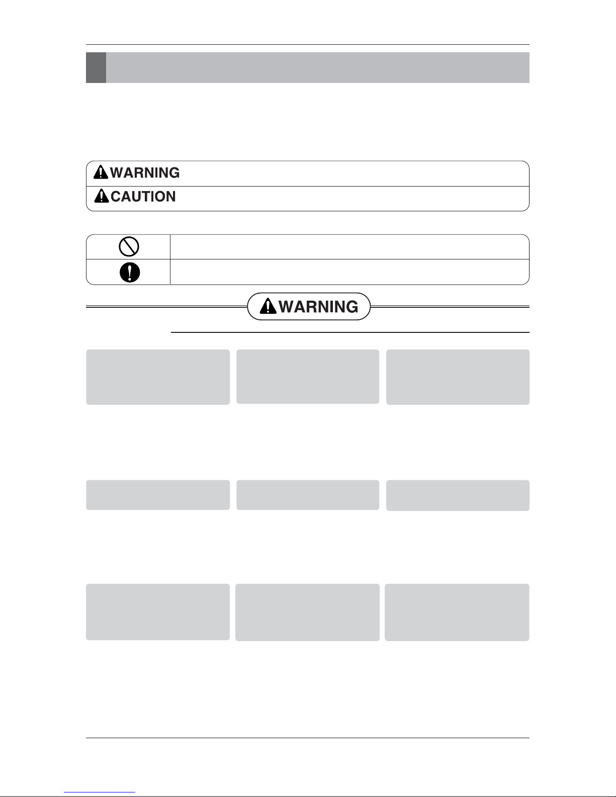
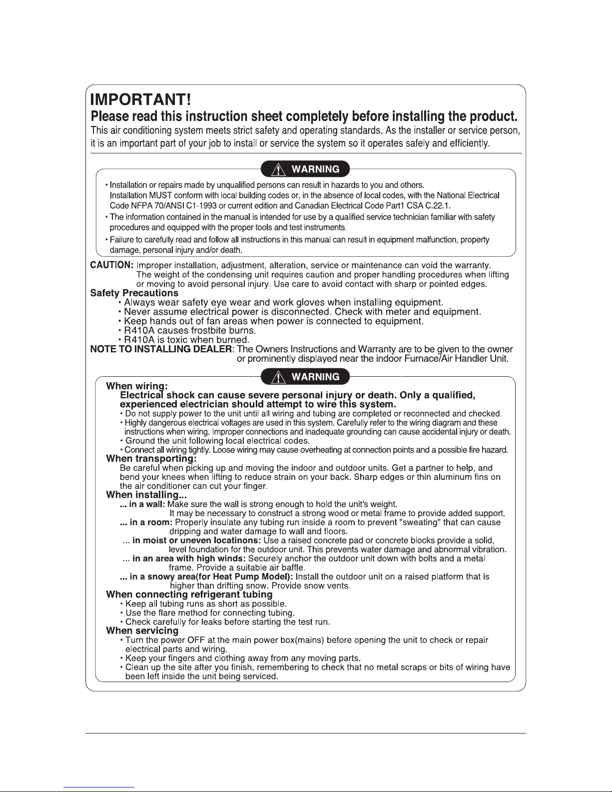
Safety Precautions
Safety Precautions
To prevent injury to the user or other people and property damage, the following instructions must be followed.
■ Be sure to read before installing the air conditioner.
■ Be sure to observe the cautions specified here as they include important items related to safety.
■ Incorrect operation due to ignoring instruction will cause harm or damage. The seriousness is classified by the
following indications.
■ Meanings of symbols used in this manual are as shown below.
This symbol indicates the possibility of death or serious injury.
This symbol indicates the possibility of injury or damage to properties only.
Be sure not to do.
Be sure to follow the instruction.
■ Installation
Do not use a defective or
underrated circuit breaker.
Use this appliance on a dedicated circuit.
• There is risk of fire or electric
shock.
For electrical work, contact
the dealer, seller, a qualified
electrician, or an Authorized
Service Center.
• Do not disassemble or repair
the product. There is risk of
fire or electric shock.
Always ground the product.
• There is risk of fire or electric
shock.
Install the panel and the
cover of control box securely.
• There is risk of fire or electric
shock.
Always install a dedicated
circuit and breaker.
• Improper wiring or installation
may cause fire or electric
shock.
Use the correctly rated breaker or fuse.
• There is risk of fire or electric
shock.
Do not modify or extend the
power cable.
• There is risk of fire or electric
shock.
Do not let the air conditioner
run for a long time when the
humidity is very high and a
door or a window is left open.
• Moisture may condense and
wet or damage furniture.
Be cautious when unpacking
and installing the product.
• Sharp edges could cause
injury. Be especially careful of
the case edges and the fins
on the condenser and evaporator.
6 Vertical Air Handling Unit
■ Installation
Always check for gas (refrigerant) leakage after installation or repair of product.
• Low refrigerant levels may
cause failure of product.
Install the drain hose to
ensure that water is drained
away properly.
• A bad connection may cause
water leakage.
Keep level even when
installing the product.
• To avoid vibration or water
leakage.
Do not install the product
where the noise or hot air from
the outdoor unit could damage the neighborhoods.
• It may cause a problem for your
neighbors.
Use two or more people to lift
and transport the product.
• Avoid personal injury.
Do not install the product
where it will be exposed to
sea wind (salt spray) directly.
• It may cause corrosion on the
product. Corrosion, particularly on
the condenser and evaporator
fins, could cause product malfunction or inefficient operation.
If you eat the liquid from the
batteries, brush your teeth and see doctor. Do
not use the remote if the batteries have leaked.
• The chemicals in batteries could cause burns or
other health hazards.
Safely dispose of the packing materials.
• Packing materials, such as nails and other metal or
wooden parts, may cause stabs or other injuries.
• Tear apart and throw away plastic packaging bags
so that children may not play with them. If children
play with a plastic bag which was not torn apart,
they face the risk of suffocation.
Safety Precautions
■ Operation
For installation, always contact the dealer or an
Authorized Service Center.
• There is risk of fire, electric
shock, explosion, or injury.
Do not install the product on
a defective installation stand.
• It may cause injury, accident,
or damage to the product.
Be sure the installation area
does not deteriorate with age.
• If the base collapses, the air
conditioner could fall with it,
causing property damage,
product failure, and personal
injury.
Do not store or use flammable gas or combustibles near the product.
• There is risk of fire or failure of product.
ENGLISH
Installation Manual 7
Installation
• Where optimum air distribution can be ensured.
• Where nothing blocks air passage and install the duct work.
• Where condensate can be properly drained.
• Where the ceiling is strong enough to bear the indoor unit weight.
• Where the false ceiling is not noticeably on an incline.
• Where sufficient clearance for maintenance and service can be ensured.
• Where piping between indoor and outdoor units is possible within the allowable limit. Refer to the
installation manual for the outdoor unit.
• Vertical Air Handling Unit can be installed for upflow and horizontal-left positions.
NOTE : The primary and secondary drain line must be trapped to allow proper drainage of condensate
water, If the secondary drain line is not used, it must be capped.
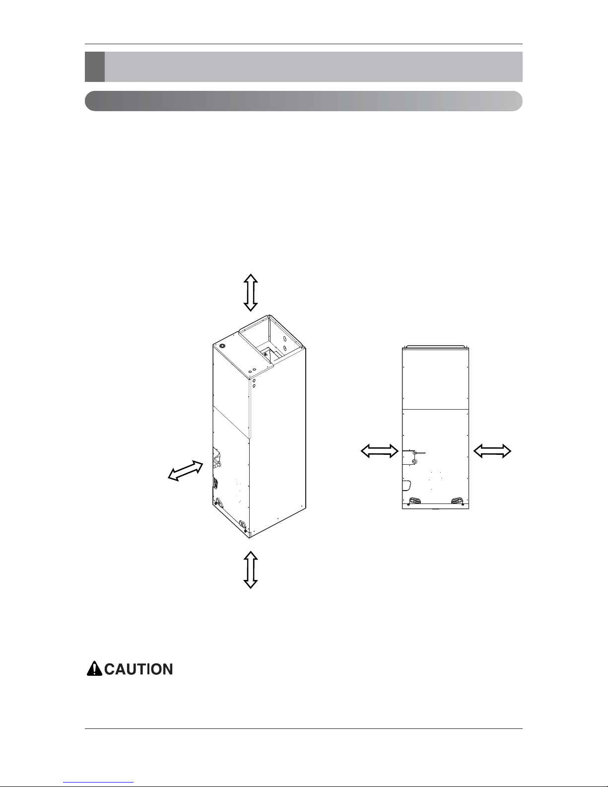
Selection of the best location
More than 23-5/8 inch
(600 mm)
clearance from
access panels
for Service
More than
10 inch
(250mm)
More than
10 inch
(250mm)
More than 14 inch
(350 mm)
More than 14 inch
(350 mm)
In the case of sea coast installation, salt residue may cause corrosion of cabinet and component
parts. Please take appropriate anti-corrosion measures.
8 Vertical Air Handling Unit
Installation
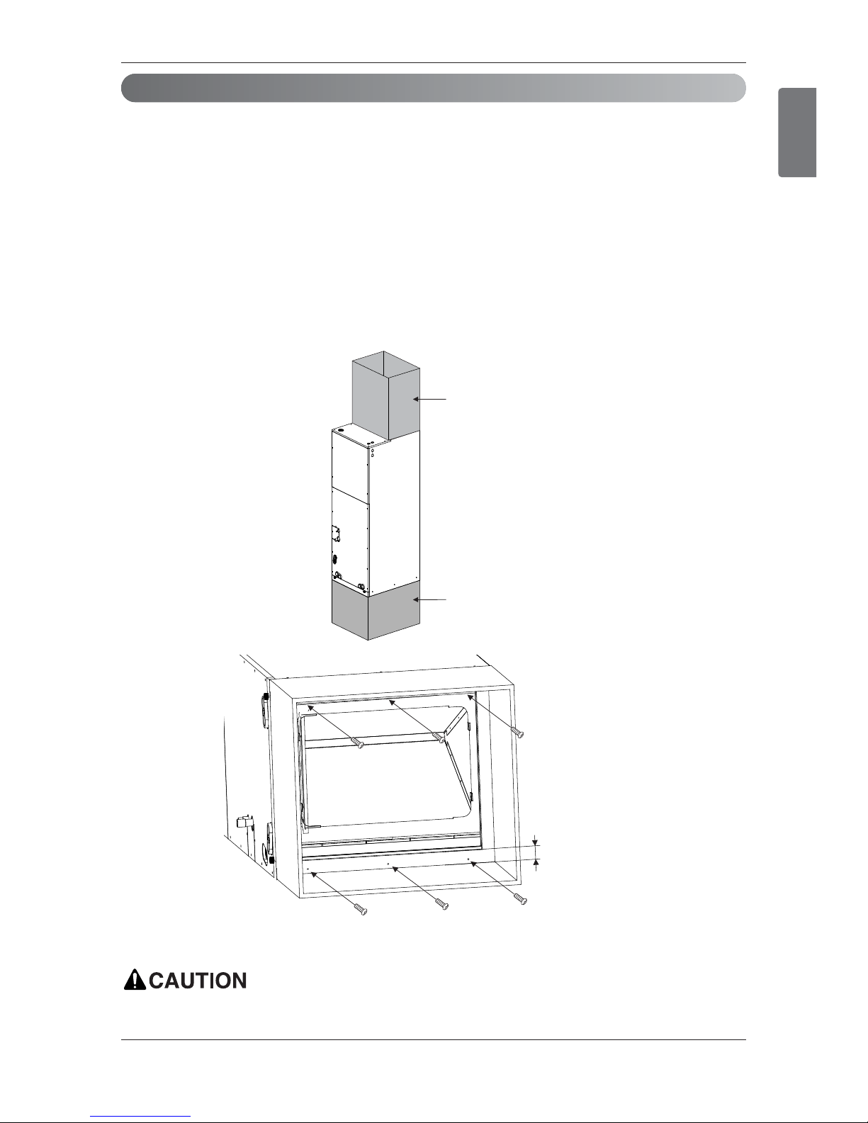
• Position unit for plenum installation.
• The plenum should be secured in order to support the installation of adapter callers accommodate the
installation of any duct work.
• Seal all duct work according to local codes to prevent air leakage. Ensure that filter access is unobstructed.
• The air handler support platform should be sturdy enough to support the cabinet plus any accessory
components including filter box.
• The minimum height clearance is 14inches(350mm) to maintain proper air flow.
• Vibration isolators (purchased locally) must be placed between the unit and the pedestal.
• An illustration showing an example of where a vibration isolator should be added would clarify what
the installing contractor should do to properly position the isolator.
More than 6 screws (M4*25L)
Field
Supplied Return
Plenum
More than
1inch (25mm)
Field Supplied
Supply Duct
Installation
Upflow Installation
Do not connect the screws on Front and Rear side, it may cause the filter can not be mounted.
ENGLISH
Installation Manual 9
10 Vertical Air Handling Unit
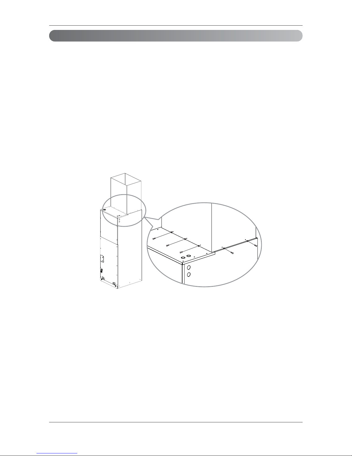
Installation
Duct work
• Over 10 screws should be used for joining supply duct with the unit.
• To prevent vibration transmission, exploit flexible connectors between duct and the unit. It is mandatory that the flexible connector between unit and duct at discharge connection should be made off heat
resistive material when electric heater is installed.
• Duct work must be insulated and covered with vapor barrier when routed through unconditioned
space.
• Internal acoustical insulation lining may necessary for the metal duct system if it do not have 90°
elbow and 10ft. of main duct to first branch takeoff.
• It is advised that a fibrous duct work could be used as a substitute if built and installed in accordance
with the most recent edition of SMACNA construction standard on fibrous glass ducts.
• Collectively fibrous duct work and acoustical lining shall obey National Fire Protection Association
standards 90A or B as tested by UL standard 181 for class 1 air ducts.
• Seal around the delivery duct subsequent to when the duct is secured so that to facilitate prevention
of air leakage.
More than 10 screws
(M4*25L)
Installation Manual 11
ENGLISH
• It is particular that the units should not be installed in such a manner that the access panels facing up
or down
• It should be confirmed that the installation is in accordance with all relevant building codes that may
necessitate installation of external condensate pan.
-Set up a support for unit by locating it in or above external condensate pan.
• Angle steel support brackets with threaded rods which supporting the units from the underside should
be used as shown in the figure below if the units are suspended.
• If not suspended then also it should be supported as same as mentioned above and also carefully
isolated to avoid sound transmission. The size of the support should comparatively bigger than the
unit and the unit must be place at centre of the support.
• Locally available vibration isolators must be placed between the unit and the support.
• The same installation method of up flow type has to be used in the case of Return Plenum and supply duct.
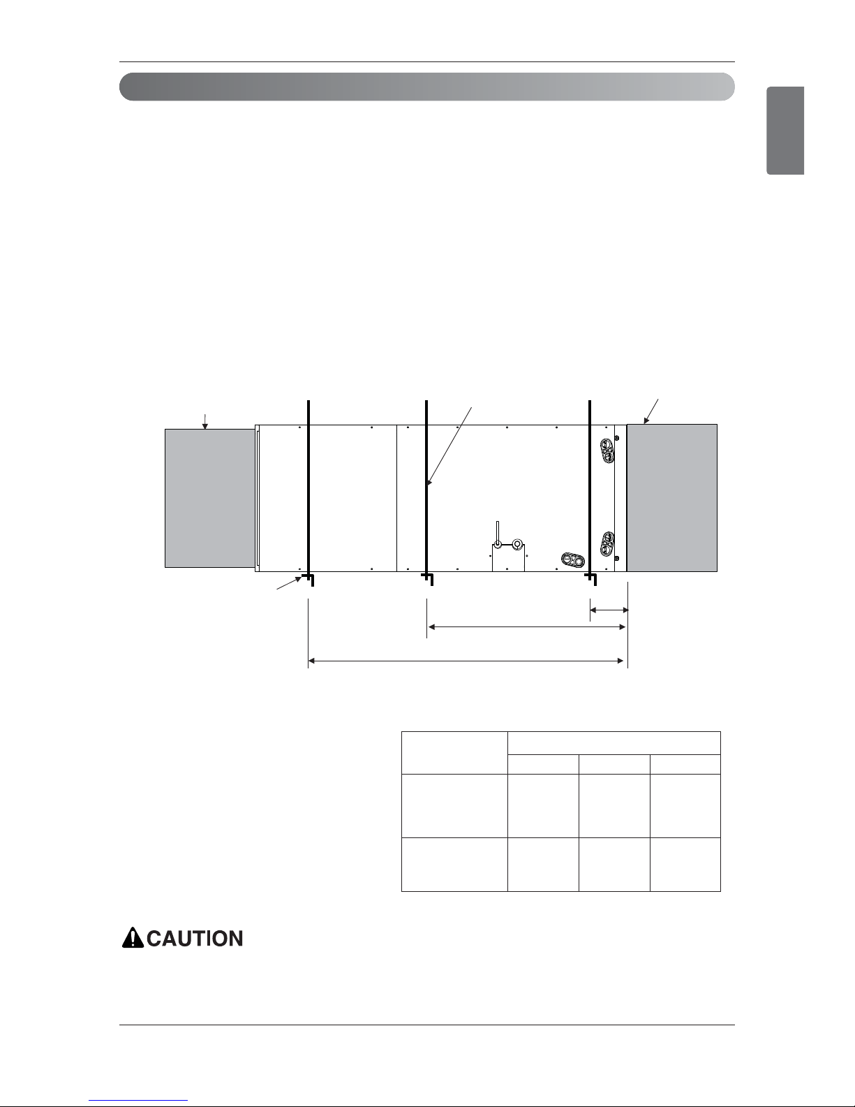
Installation
Horizontal-left Installation
To ensure proper drainage for horizontal installations, unit must be installed so it is within 1/8” level of
the length and width of unit.
B
A
C
More than 1-1/2
inch(38 mm) X 1-1/2
inch(38 mm) angle
Recommended
length more than 26
inch(660 mm) with
2 inch(50 mm)
clearance on both
sides of unit
More than 3/8 inch
(9.5mm) threaded rod
Field Supplied
Supply Duct
Field Supplied
Return Plenum
Suspension support locations
Caapcity
(kBtu(RT))
Dimension
ABC
18(1.5)
24(2.0)
30(2.5)
36(3.0)
4(100) 23(580)
41-1/2
(1050)
42(3.5)
48(4.0)
54(4.5)
4(100) 29(730) 48(1220)
(Unit : inch(mm))
 Loading...