

LG MFL62725501 User Manual
GAS COOKTOP
To contact LG Electronics, 24 hours a day,
7 days a week:
1-800-243-0000 (U.S.A.)
1-888-542-2623 (Canada)
Or visit us on the Web at:
us.lge.com (U.S.A.)
ca.lge.com (Canada)
INSTALLATION INSTRUCTIONS
Please read this guide thoroughly
before installation.
BEFORE YOU BEGIN
Read these instructions completely
and carefully.
Installation of this cooktop must conform with local
codes, or in the absence of local codes, with the
National Fuel Gas Code, ANSI Z223.1/NFPA.54,
latest edition. In Canada, installation must
conform with the current Natural Gas Installation
Code, CAN/CGAB149.1 or the current Propane
Installation Code, CAN/CGA-B149.2, and with
local codes where applicable. This cooktop has
been design-certified by CSA International
according to ANSI Z21.1, latest edition and
Canadian Gas Association according to
CAN/CGA-1.1 latest edition.
As with any appliance using gas and generating
heat, there are certain safety precautions you
should follow. You will find these precautions in
the Important Safety Information section in your
User’s Guide. Read them carefully.
• IMPORTANT – Save these instructions
for local electrical inspector’s use.
• IMPORTANT – Observe all governing
codes and ordinances.
P/No.: MFL62725501
Note to Installer: Leave these instructions with
the appliance after installation is completed.
Note to Consumer: Keep the User’s Guide and
Installation Instructions for future reference.
NOTE: This appliance must be properly
grounded.
• The electrical diagram is in an envelope
attached to the back of the cooktop.
• Skill level – Installation of this appliance
requires basic mechanical skills.
• Proper installation is the responsibility of the
installer.
• Product failure due to improper installation is
not covered under the Warranty.
• Remove all tape and packaging.
• Make sure the burners are properly seated
and level.
• Take the accessory pack off of the cooktop.
• Check to be sure that no cooktop parts have
come loose during shipping.
INSTALLATION INSTRUCTIONS
2
FOR YOUR SAFETY
-Do not store or use combustible materials,
WARNING:
If the information in this
manual is not followed exactly, a fire or
explosion may result causing property
damage, personal injury or death.
gasoline or other flammable vapors and
liquids in the vicinity of this or any other
appliance.
WHAT TO DO IF YOU SMELL GAS
Do not try to light any appliance.
Do not touch any electrical switches,
Do not use any phone in your building.
Immediately call your gas supplier from a neighbor′s
phone. Follow the gas supplier instructions.
If you cannot contact your gas supplier, call the
fire department.
2
READ ALL INSTRUCTIONS BEFORE INSTALLATION
PREPARING FOR INSTALLATION
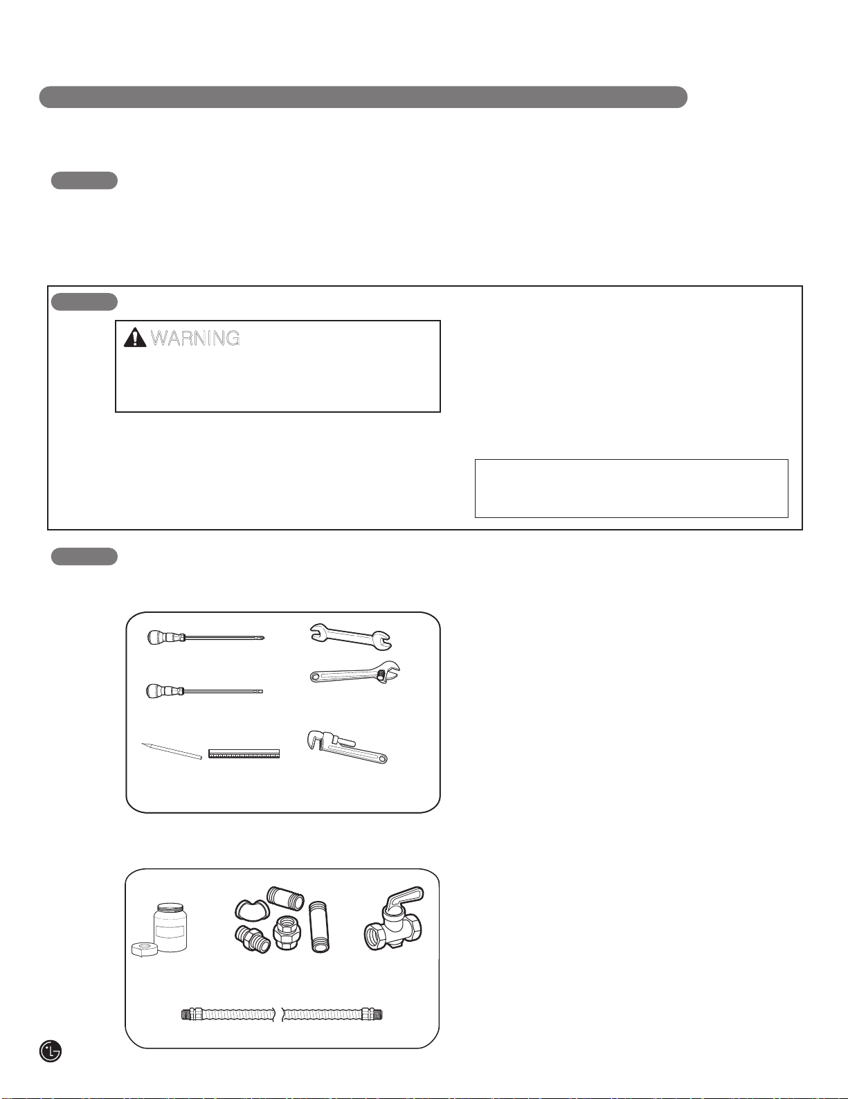
TOOLS YOU WILL NEED MATERIALS YOU MAY NEED
MATERIALS YOU MAY NEED
• Gas line shut-off valve
•
To reduce the possibility of gas leaks, apply teflon
tape or a thread compound approved for use
with LP or Natural gases to all threaded connections.
• Flexible metal appliance connector (5/8” I.D.)
A 3-foot length is recommended for ease of
installation but other lengths are acceptable.
Never use an old connector when installing a
new cooktop.
•
Flare union adapter for connection to gas supply
line (3/4” or 1/2” NPT x 5/8” I.D.)
• Flare union adapter for connection to pressure
regulator on cooktop. (1/4” NPT x 1/2” I.D.)
• Liquid leak detector or soapy water.
IN THE COMMONWEALTH OF MASSACHUSETTS
• This product must be installed by a licensed
plumber or gas fitter.
• When using ball type gas shut-off valves,
they shall be the T-handle type.
•
•
•
•
•
•
A flexible gas connector, when used, must not
exceed 3 feet in length.
Phillips screwdriver
Flat-blade screwdriver
Pencil and ruler
Pipe wrench(2)
(one for support)
Open-end or
adjustable wrench
Installation and service must be performed by
a
qualified installer, service agency or the gas
supplier.
Phillips screwdriver
Open-end or
Flat-blade screwdriver
Pencil and ruler
adjustable wrench
Pipe wrench(2)
(one for support)
Sealant
Joint
Sealant
Pipe Fittings
Flexible Connector
Shut Off
Valve
INSTALLATION INSTRUCTIONS
3
INSTALLATION SAFETY INSTRUCTIONS
BEFORE YOU BEGIN
Remove all tape and packing materials before using the cooktop. Dispose all plastic bags after
unpacking the cooktop. Never allow children to play with packing materials.
IMPORTANT SAFETY INSTRUCTIONS
Read these instructions completely and carefully. Improper installation, adjustment, alteration,
service or maintenance can cause injury or property damage.
For assistance or additional information, consult a qualified installer, service agency, manufacturer
(dealer) or your gas supplier.
Never reuse old flexible connectors. The use of old flexible connectors can cause gas leaks and
personal injury. Always use NEW flexible connectors when installing a gas appliance.
This symbol will alert you to hazards or unsafe practices which could
cause serious bodily harm or death.
This is the safety alert symbol. This symbol alerts you to potential hazards that can kill or
hurt you and others. All safety messages will follow the safety alert symbol and either the
word “WARNING” or “CAUTION”.
This symbol will alert you to hazards or unsafe practices which could
cause bodily injury or property damage.
WARNING
CAUTION
IMPORTANT: Remove all packing material and
literature before connecting gas and electrical supply.
•
Let your cooktop installed by a qualified installer.
•
Your cooktop must be electrically grounded in
accordance with local codes or, in the absence of
local codes, in accordance with the National
Electrical Code (ANSI/NFPA 70, latest edition). In
Canada, electrical grounding must be in accordance
with the current CSA C22.1 Canadian Electrical
Code Part 1 and/or local codes.
Refer to “3. Electrical Connections” in this manual.
•
Be sure the wall coverings around the cooktop can
withstand heat generated by the cooktop up to 200°F.
•
Avoid placing cabinets above the cooktop.
To minimize the hazard caused by reaching over the
open flames of operating burners, install a ventilation
hood over the cooktop that projects forward at least
5” beyond the front of the cabinets.

4
INSTALLATION INSTRUCTIONS
•
The ventilating hood must be constructed of sheet
metal not less than 0.0122” thick. Install above the
cooktop with a clearance of not less than 1/4”
between the hood and the underside of the
combustible material or metal cabinet.
The hood
must be at least as wide as the appliance
and
centered over the appliance. Clearance between
the cooking surface and the ventilation hood surface
MUST NEVER BE LESS THAN 24 INCHES.
EXCEPTION:
Installation of a listed microwave oven
or cooking appliance over the cooktop shall conform
to the installation instructions packed with that
appliance.
• If cabinets are located above the cooktop, allow a
minimum clearance of 30” between the cooking
surface and the bottom of unprotected cabinets.
• If a 30” clearance between cooking surface and
overhead combustible material or metal cabinets
cannot be maintained, protect the underside of the
cabinets above the cooktop with not less than 1/4”
insulating millboard covered with sheet metal not
less than 0.0122” thick. Clearance between the
cooking surface and protected cabinets MUST
NEVER BE LESS THAN 24 INCHES.
•
•
•
The vertical distance from the plane of the cooking
surface to the bottom of adjacent overhead cabinets
extending closer than 1” to the plane of the cooktop
sides must not be less than 18”. (See the
Dimensions and Clearances illustration in this
manual.)
CAUTION:
Items of interest to children
should not be placed in cabinets above the cooktop.
- children climbing on the cooktop to reach items
could be seriously injured.
INSTALLATION SAFETY INSTRUCTIONS (continued)
Do not abstruct the combustion or ventilation air.
Leak testing of the appliance shall be conducted
according to the manufacturer’s instructions.
5
INSTALLATION INSTRUCTIONS
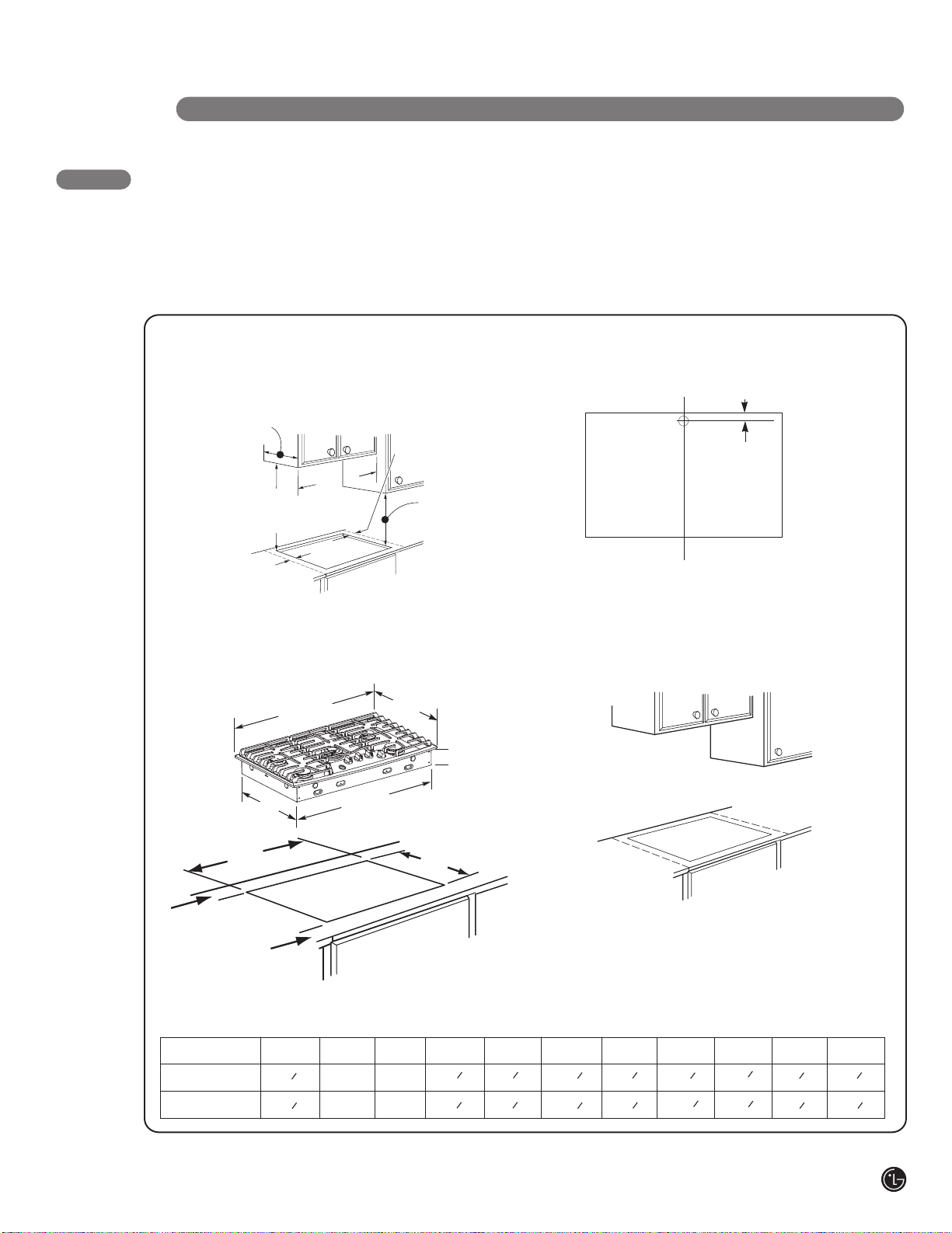
DIMENSIONS AND CLEARANCES
Provide enough clearances between the cooktop
and adjacent combustible surfaces. These dimensions
must be met for safe use of your cooktop.
The location of the electrical outlet and pipe opening
may
be adjusted to meet specific requirements.
MAINTAIN THE FOLLOWING
1.
MINIMUM CLEARANCE
DIMENSIONS
13˝MAX. Depth of unprotected
overhead cabinets
30˝MIN. clearance
from countertop to
unprotected overhead
surface
A˝MIN. clearance
from cutout to side
wall on the left of
unit.
COOKTOP AND CUTOUT
2.
B″MIN
A
A
A˝MIN. clearance from
3 3/4 MIN.
cutout to side wall on
the right of the unit
18˝MIN. height
from countertop
to nearest cabinet
on either side of
unit
DIMENSIONS
The cooktop may be placed with 2 3/4” clearance to
the back wall.
RECOMMENDED GAS SUPPLY
3.
LOCATION FROM BACKWALL
1” Min. From Backwall
Recommended
gas supply
location
From Cutout
Center Line
C
L
MAKE SURE WALL COVERINGS,
4.
COUNTERTOP AND CABINETS
AROUND COOKTOP CAN
WITHSTAND HEAT(UP TO 200℉)
GENERATED BY COOKTOP
G
depth
H
width cut
L
L″MIN.
Between
cutout
and the wall
behind the
cooktop
K″MIN.
From front
edge of cutout
and front edge
of countertop
MODEL
30″ Cooktop
36″ Cooktop
K
A
13
11
13
11
C
width
″
16
″
16
F
width
B
30″
36″
D
depth
C
30″
36″
E
height
J
depth cut
D
11
21
11
21
Wall covering,
cabinets and
countertop
must withstand
heat up to
200°F
To ensure accuracy, it is best to make
a template when cutting the opening
in the counter
16
16
″
″
E
3
″
4
3
3
″
4
3
F
1
28
5
33
4
8
″
″
G
3
″
8
19
3
″
8
19
H
1
2
28
15
33
″
16
″
J
11
″
16
19
11
″
16
19
K L
5
″
8
1
5
1
2
″
8
2
3
″
4
3
″
4
 Loading...