

LG MFL39754838 Installation Manual

INSTALLATION MANUAL
AIR CONDITIONER
TYPE : WALL MOUNTED
P/No. MFL39754838
LG Electronics India Pvt. Ltd.
Registered Office: Plot No. 51, Surajpur Kasna Road,
Greater Noida - 201 306 (U.P.) INDIA
Tel: 0120-2560900 Fax: 0120-2560957
www.lg.com
Please read this installation manual completely before installing the product.
When the power cord is damaged, replacement work shall be
performed by authorized personnel on;y.
Installation work must be performed in accordance with the national wiring
standards by authorized personnel only.
Please retain this installation manual for
future reference after reading it thoroughly.
(Recommended 24°C is suitable for human body)
(Refer page no. 21 and 22 owner's manual)

6 Installation Parts provided with the Unit
6 Installation Parts you must purchase
7 Required Tools
8
10
11
11
12
14
15
17
18
20
Connecting the cable between indoor
unit and outdoor unit
Checking the drainage and forming the
piping
Air purging
Test running
Installation of Indoor & Outdoor Unit
Flaring Work and Connection of Piping
TABLE OF CONTENTS
5
INSTALLATION PARTS
INSTALLATION
6
8
Connection of piping (Indoor)
For right rear piping
For left rear piping
Connection of piping (Outdoor)
Type ‘A’ Screw
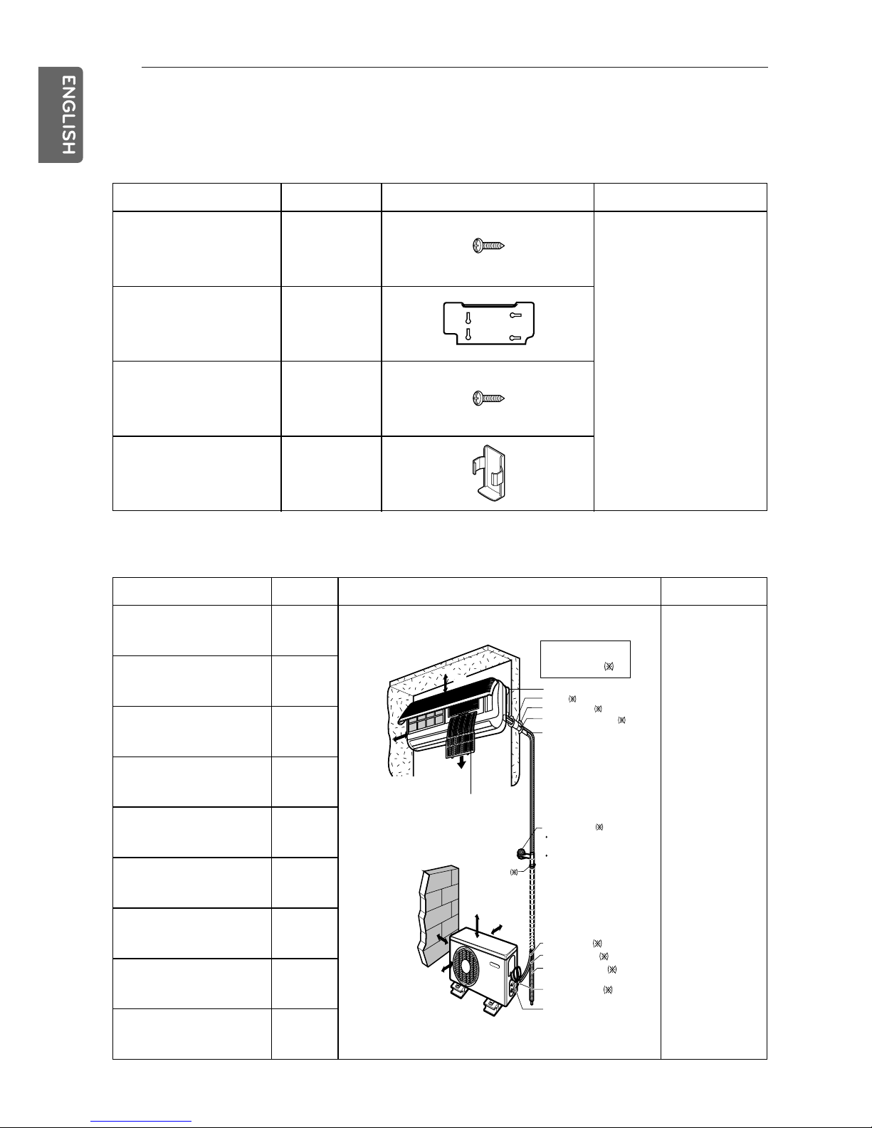
INSTALLATION PARTS
Installation parts provided with the unit
Type ‘A’ Screw Quantity Shape Others
Type ‘A’ Screw Quantity Shape Others
4
Installation Plate
Type ‘B’ Screw
Holder Remote Control
1
2
1
Paper pattern for
installation.
Owner’s Manual
Installation Manual
•
•
•
Installation parts you must purchase
Paper pattern
for installation.
Owner’s
Manual
Installation
Manual
•
•
•
Sleeve
Bushing Sleave
Putty (Gum type sealer)
Vinyl tape (Wide)
Gas side piping
Liquid side piping
Additional drain pipe
Vinyl tape (Narrow)
Saddle
INSTALLATION PARTS
6
Installation parts you
must purchase
Installation plate
Sleeve
Bushing-Sleeve
Putty(Gum Type Sealer)
Bend the pipe as closely
on the wall as possible,
but be careful that it
doesn't break.
Vinyl tape (Wide)
Apply after carrying out a
drainahe test.
To carry out the drainage
test, remove the air filters
and pour water into the heat
exchanger.
Gas side piping
Liquid side piping
Additional drain pipe
Vinyl tape (Narrow)
Connecting cable: Cooling & Heat pump: 2EA
Cooling only: 1EA
More than 70cm
More than
10cm
More than
60cm
Saddle
More than
10cm
More than
5cm
Air filter
(Left and right
are identical)
More than
20cm
1
2
3
4
5
6
7
8
9
10
11
12
13
14
Installation Tools
S.No. Required Tools
Level Gauge
Screw Driver
Electric Drill
Hole Core Drill (Dia-70mm)
Flaring Tool Set
Specified torque wrenches 1.8kg.m, 4.2kg.m, 5.5kg.m, 6.6kg.m
(Different depending on model no.)
Spanner (Half Union)
A glass of water
Hexagonal Wrench
Gas-Leak Detector
Vacuum Pump
Gauge Manifold
Owner’s Manual
Thermometer
INSTALLATION TOOLS
7
 Loading...