

LG M227WDP, M227WDP-PZ, M237WDP-PC, M237WDP-PZ, M237WDP-PX Owner's Manual
...
ENGLISH
OWNER’S MANUAL
MONITOR TV
Please read this manual carefully before operating
your set and retain it for future reference.
MONITOR TV MODELS
M197WDP
M227WDP
M237WDP
www.lge.com

1
PREPARATION
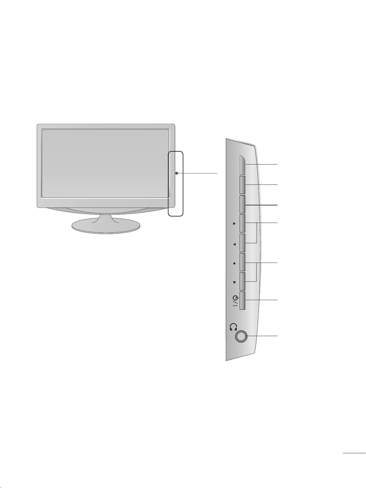
FRONT PANEL CONTROLS
■
This is a simplified representation of the front panel. The image shown may be somewhat different from your set.
INPUT
MENU
VOL PROK
PROGRAMME
Buttons
VOLUME
Buttons
MENU
Button
OK
Button
INPUT
Button
Power
Button
Headphone
Jack
22
PREPARATION
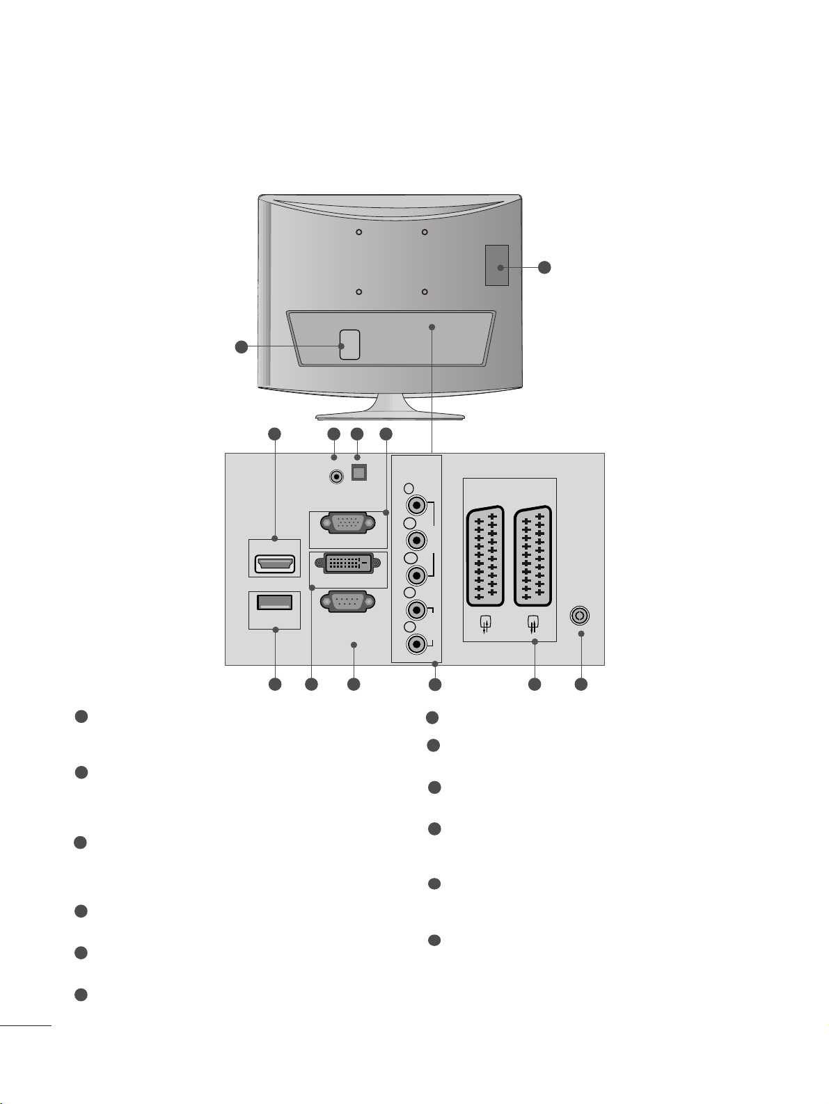
BACK PANEL INFORMATION
■
This is a simplified representation of the back panel. The image shown may be somewhat different from your set.
<M197WDP/M227WDP>
V 1
V 2
3
9
10
2
1
87 1211
64 5
PPCCMMCC IIAA ((PPeerrssoonn aall CCoommppuu tteerr MMeemmoorryy CCaa rrdd
IInntteerrnn aa ttiioonnaall AAssssooccii aattiioonn)) CCaarr dd SSll oott
This feature is not available in all countries.
PPoowweerr CCoorr dd SSoocckk eett
This set operates on AC power. The voltage is indicated
on the Specifications page. Never attempt to operate
the set on DC power.
HHDDMMII IInnppuutt((NNoott SSuu ppppoorr tt PPCC))
Connect a HDMI signal to HDMI IN.
Or DVI (VIDEO) signal to HDMI IN with DVI to HDMI
cable.
RR GG BB //DDVVII AA uuddii oo IInnppuu tt
Connect the audio from a PC.
OOppttii cc aa ll DDii ggii tt aall AAuuddii oo OOuutt
Connect digital audio from various types of eguipment.
RR GGBB IINNPP UUTT ((PP CC))
Connect the output from a PC.
UUSS BB IINN
DDVVII--DD IInn pp uutt
Connect the output from a PC.
RR SS--2233 22CC II NN ((CCOO NN TTRROO LL && SSEERRVV IICC EE)) PPOORRTT
Connect to the RS-232C port on a PC.
CC oo mmppoonn eenn tt IInn ppuutt
Connect a component video/audio device to these
jacks.
EEuu rroo SSccaarr tt SSoocckkeett (( AAVV11//AAVV22))
Connect scart socket input or output from an external
device to these jacks.
AA nnttee nnnnaa IInnppuu tt
Connect over-the-air signals to this jack.
1
2
3
4
5
6
7
8
9
10
11
12
AUDIO IN
(RGB/DVI)
HDMI IN
USB IN
OPTICAL
DIGITAL
AUDIO OUT
RGB IN (PC)
DVI-D (PC)
RS-232C IN
(CONTROL & SERVICE)
COMPONENT
IN
Y
P
B
VIDEO
P
R
L
AUDIO
R
AV 1
AV 2
ANTENNA/
CABLE IN
33
PREPARATION
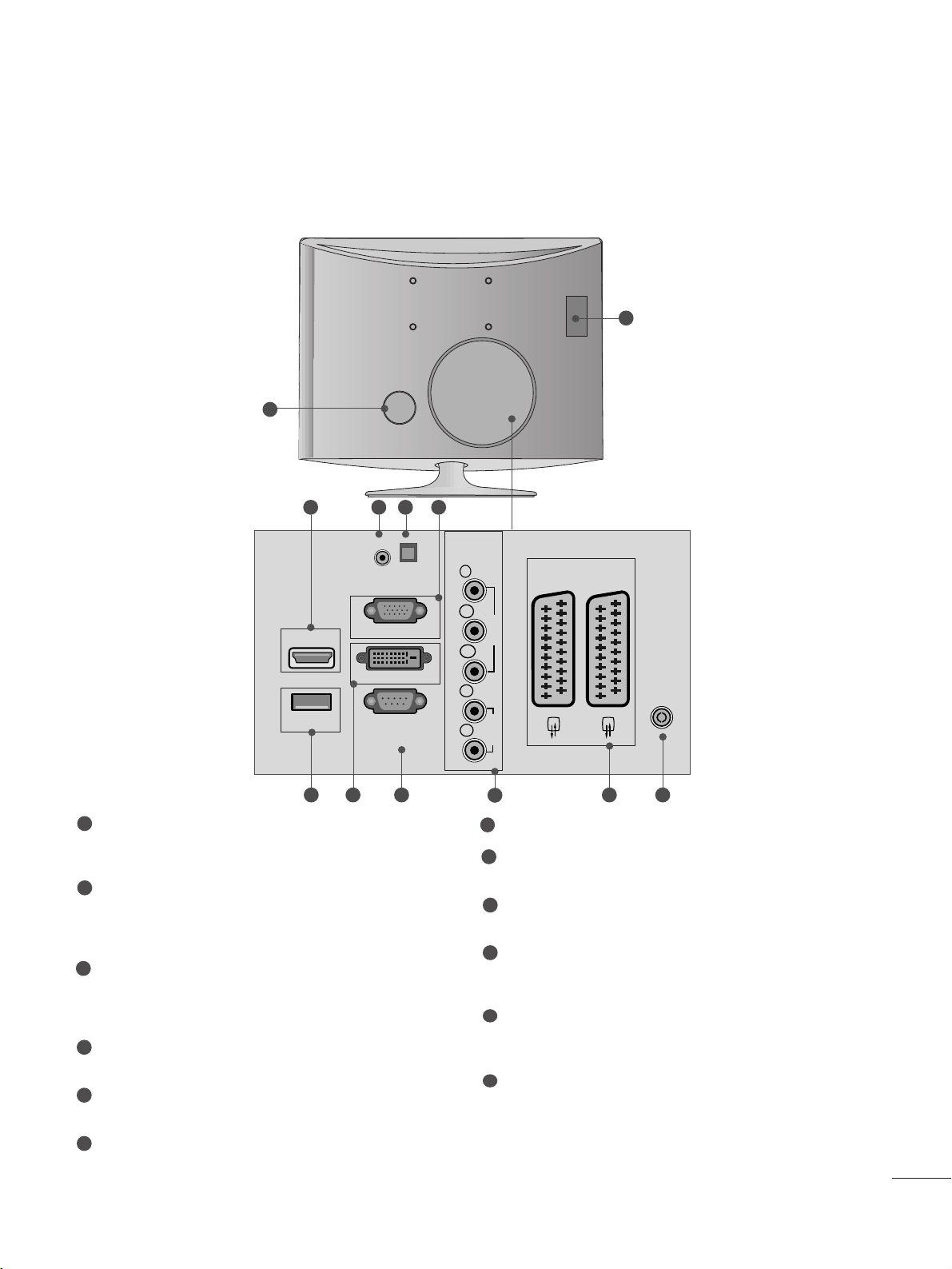
<M237WDP>
AUDIO IN
(RGB/DVI)
OPTICAL
DIGITAL
AUDIO OUT
VIDEO
COMPONENT
IN
AUDIO
Y
P
B
P
R
L
R
RS-232C IN
(CONTROL & SERVICE)
USB IN
RGB IN (PC)
DVI-D (PC)
HDMI IN
AV 1V 1 AV 2V 2
ANTENNA/
CABLE IN
3
9
10
87 1211
64 5
PPCCMMCC II AA (( PPeerr ssoonnaall CCoommppuu tteerr MMeemmoorryy CCaarrdd
IInntteerrnn aa ttiioonnaall AAssssooccii aattiioonn)) CCaarr dd SSll oott
This feature is not available in all countries.
PPoowweerr CC oo rrdd SS oocc kk eett
This set operates on AC power. The voltage is indicated
on the Specifications page. Never attempt to operate
the set on DC power.
HHDD MMII IInnppuu tt((NNoott SSuuppppoorrtt PPCC ))
Connect a HDMI signal to HDMI IN.
Or DVI (VIDEO) signal to HDMI IN with DVI to HDMI
cable.
RR GG BB //DDVVII AA uuddii oo IInnppuu tt
Connect the audio from a PC.
OOppttii cc aa ll DDii ggii tt aall AAuuddii oo OOuutt
Connect digital audio from various types of eguipment.
RR GGBB IINNPP UUTT ((PP CC))
Connect the output from a PC.
UUSS BB IINN
DDVVII--DD IInn pp uutt
Connect the output from a PC.
RR SS--2233 22CC II NN ((CCOO NN TTRROO LL && SSEERRVV IICC EE)) PPOORRTT
Connect to the RS-232C port on a PC.
CC oo mmppoonn eenn tt IInn ppuutt
Connect a component video/audio device to these
jacks.
EEuu rroo SSccaarr tt SSoocckkeett (( AAVV11//AAVV22))
Connect scart socket input or output from an external
device to these jacks.
AA nnttee nnnnaa IInnppuu tt
Connect over-the-air signals to this jack.
1
2
3
4
5
6
7
8
9
10
11
12
BACK PANEL INFORMATION
■
This is a simplified representation of the back panel. The image shown may be somewhat different from your set.
2
1
44
PREPARATION
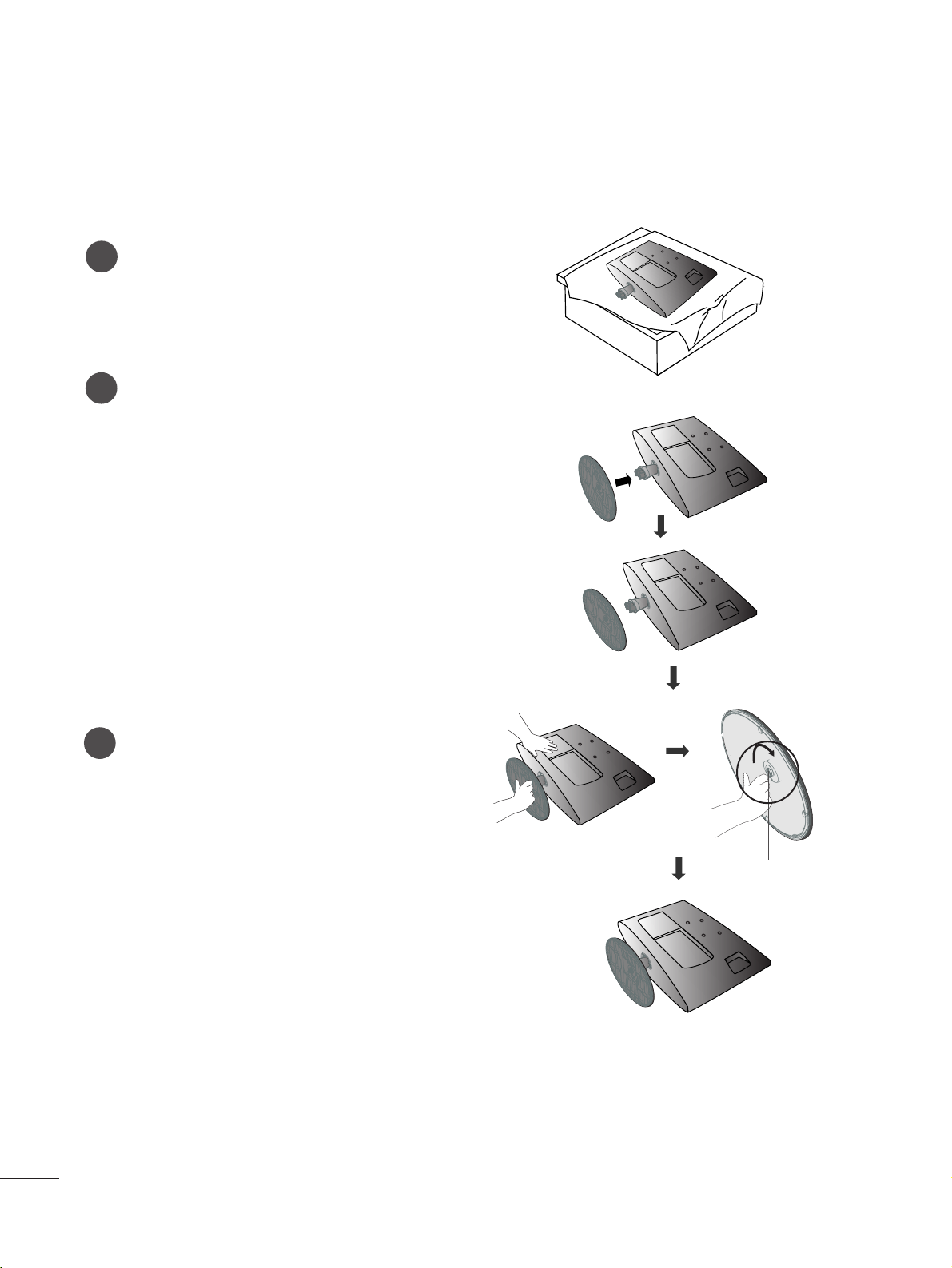
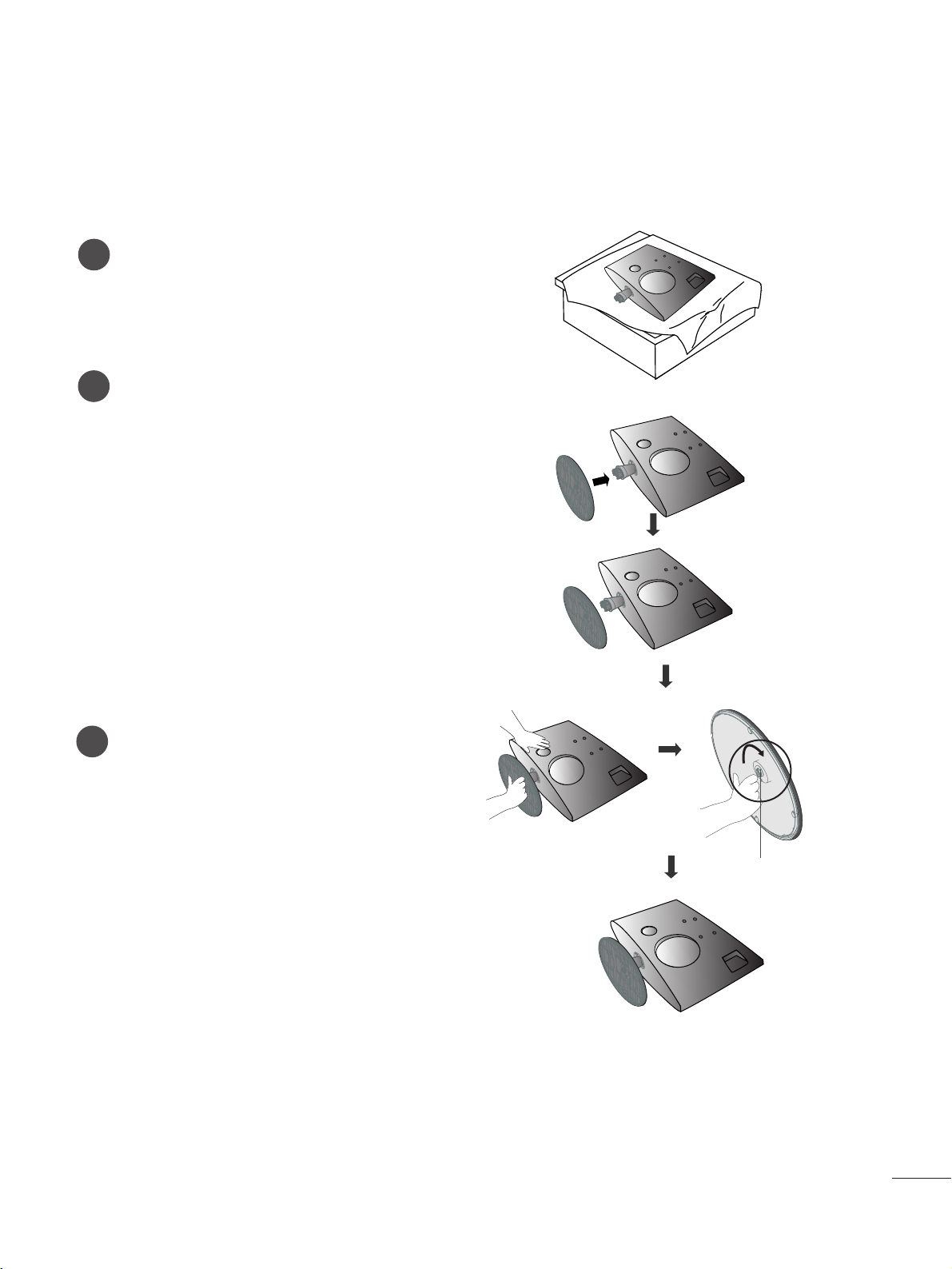
STAND INSTALLATION
■
The image shown may be somewhat different from your set.
1
2
3
Carefully place the product screen side down on a
cushioned surface that will protect product and
screen from damage.
Insert the
ss tt aa nndd bbaa ssee
into the product
Attach the monitor to the Stand Base by turning
the screw to the right.
* Turn the screw by using the screw handle
Screw
<M197WDP/M227WDP>
55
PREPARATION
<M237WDP>
STAND INSTALLATION
■
The image shown may be somewhat different from your set.
1
2
3
Carefully place the product screen side down on a
cushioned surface that will protect product and
screen from damage.
Insert the
ss tt aa nndd bbaa ssee
into the product
Attach the monitor to the Stand Base by turning
the screw to the right.
* Turn the screw by using the screw handle
Screw
66
PREPARATION
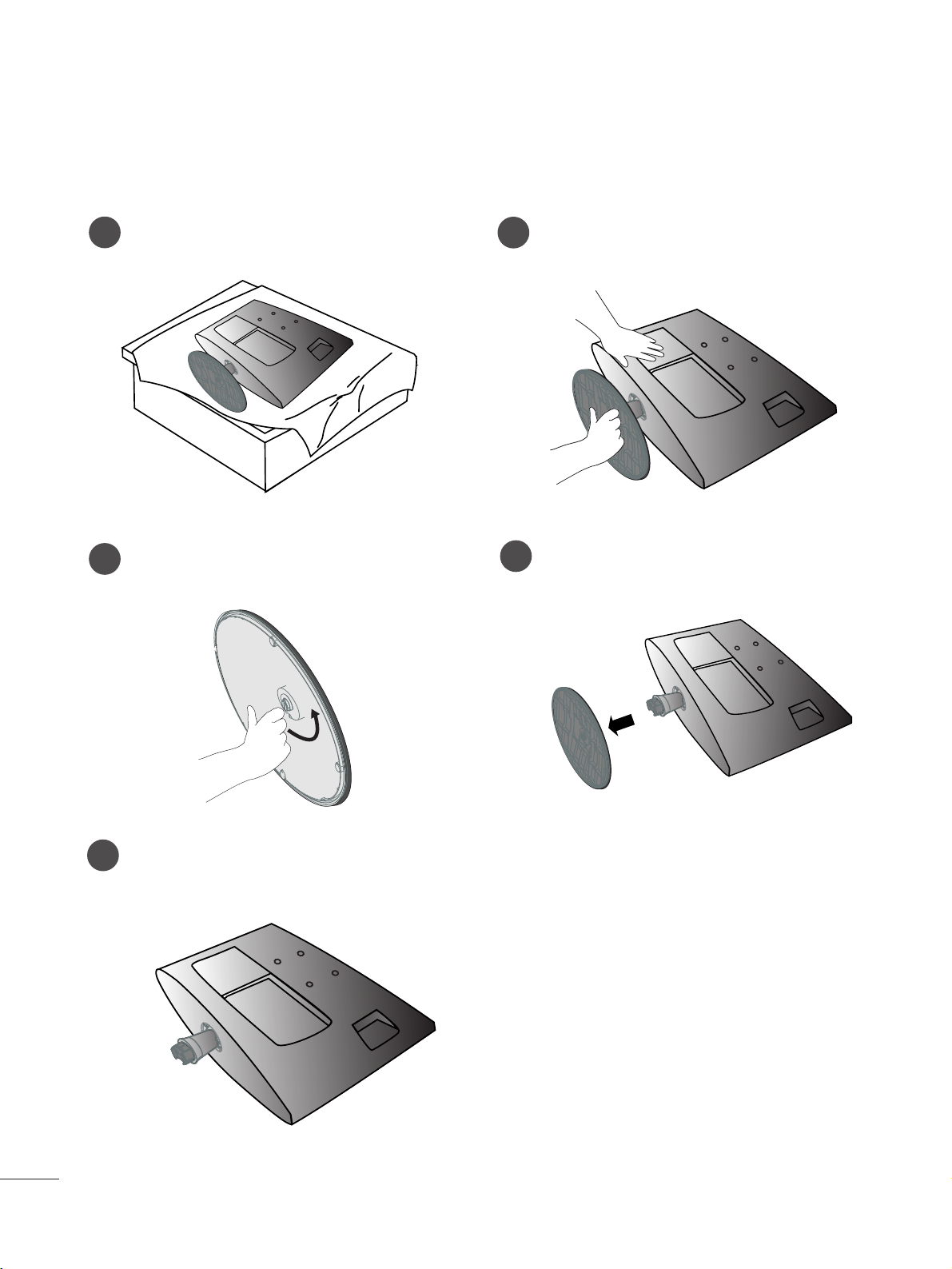
<M197WDP/M227WDP>
DETACHING STAND
1
2
3
Place the set screen side down on a cushion or
soft cloth.
Detach the monitor to the Stand Base by turning the screw to the left.
Turn the screw by using the screw handle
4
Pull the stand base.
5
■
The image shown may be somewhat different from your set.
77
PREPARATION
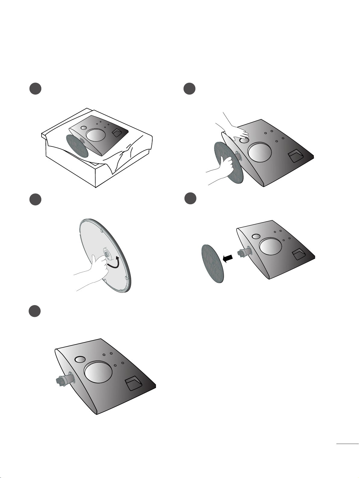
<M237WDP>
DETACHING STAND
1
2
3
Place the set screen side down on a cushion or
soft cloth.
Detach the monitor to the Stand Base by turning the screw to the left.
Turn the screw by using the screw handle
4
Pull the stand base.
5
■
The image shown may be somewhat different from your set.
88
PREPARATION
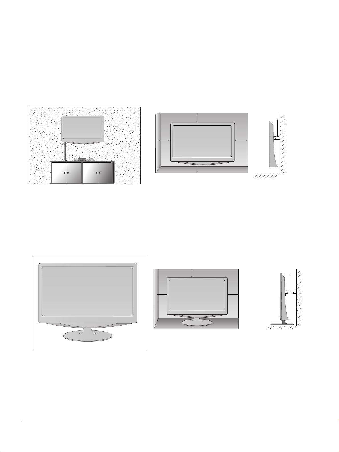
DESKTOP PEDESTAL INSTALLATION
For proper ventilation, allow a clearance of 10 cm on each side and from the wall.
10 c m
10 c m
10 c m
10 c m
WALL MOUNT: HORIZONTAL INSTALLATION
For proper ventilation, allow a clearance of 10 cm on each side and from the wall. Detailed installation
instructions are available from your dealer, see the optional Tilt Wall Mounting Bracket Installation and
Setup Guide.
10 c m
10 c m
10 cm 10 cm
10 c m
99
PREPARATION
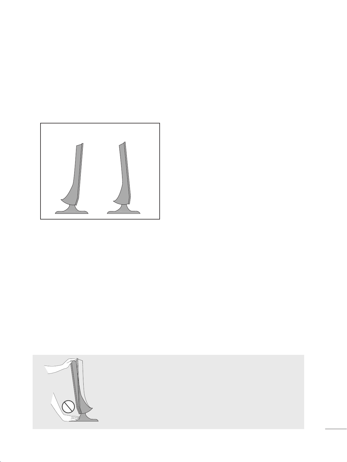
POSITIONING YOUR DISPLAY
■
The image shown may be somewhat different from your set.
Adjust the position of the panel in various ways for maximum comfort.
•• TTiill tt rraann ggee
LOCATION
Position your set so that no bright light or sunlight falls directly onto the screen. Care should be taken not to expose
the set to any unnecessary vibration, moisture, dust or heat. Also, ensure that the set is placed in a position to allow a
free flow of air. Do not cover the ventilation openings on the back cover.
If you intend to mount the set to a wall, attach Wall mounting interface (optional parts) to the back of the set.
When you install the set using the wall mounting interface (optional parts), attach it carefully so it will not drop.
- Be sure to use screws and a wall mount that meet VESA standards.
- Using screws longer than those recommended might damage the product.
- Using screws that do not meet VESA standards might either damage the product or result in it coming away from the
wall. We will not be held responsible for any damage resulting from failure to follow these instructions.
< Screw Mounting Interface Dimension >
M197WDP/M227WDP : 100 mm x 100 mm hole spacing
M237WDP : 75 mm x 75 mm hole spacing
-5°
-15°
WWaa rrnnii nngg ::
When adjusting the angle of the screen,do not put your
finger(s)in between the head of the monitor and the stand
body.You can hurt your finger(s).
1100
PREPARATION
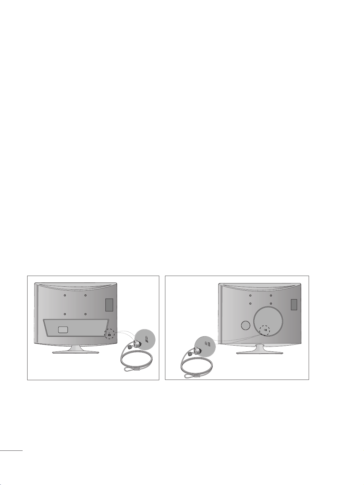
KENSINGTON SECURITY SYSTEM
- The product is equipped with a Kensington Security System connector on the back panel. Connect the
Kensington Security System cable as shown below.
- For detailed installation and use of the Kensington Security System, refer to the user’s guide provided with the
Kensington Security System.
For further information, contact
hhttttpp:: // // wwww ww ..kk eennssii nnggttoonn..ccoomm
, the internet homepage of the Kensington
company. Kensington sells security systems for expensive electronic equipment such as notebook PCs and
LCD projectors.
NOTE
- The Kensington Security System is an optional accessory.
NOTES
a. If the product feels cold to the touch, there may be a small “flicker” when it is turned on.
This is normal, there is nothing wrong with product.
b. Some minute dot defects may be visible on the screen, appearing as tiny red, green, or blue spots. However,
they have no adverse effect on the monitor's performance.
c. Avoid touching the LCD screen or holding your finger(s) against it for long periods of time.
Doing so may produce some temporary distortion effects on the screen.
<M197WDP/M227WDP> <M237WDP>
1111
ANTENNA/
CABLE IN
ANTENNA/
CABLE IN
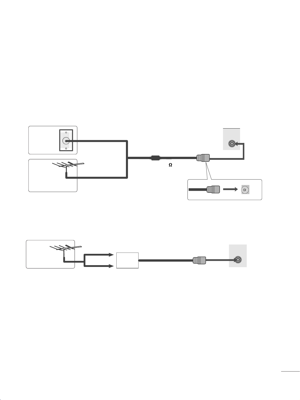
EXTERNAL EQUIPMENT SETUP
■
For optimum picture quality, adjust antenna direction.
■
An antenna cable and converter are not supplied.
■
To prevent equipment damage, never plug in any power cords until you have finished connecting all equipment.
Multi-family Dwellings/Apartments
(Connect to wall antenna socket)
Single-family Dwellings /Houses
(Connect to wall jack for outdoor antenna)
Outdoor
Antenna
(VHF, UHF)
Wal l
Antenna
Socket
RF Coaxial Wire (75 )
ANTENNA CONNECTION
Antenna
UHF
Signal
Amplifier
VHF
■
In poor signal areas, to get better picture quality, install a signal amplifier to the antenna as shown above.
■
If signal needs to be split for two TVs, use an antenna signal splitter for connection.
1122
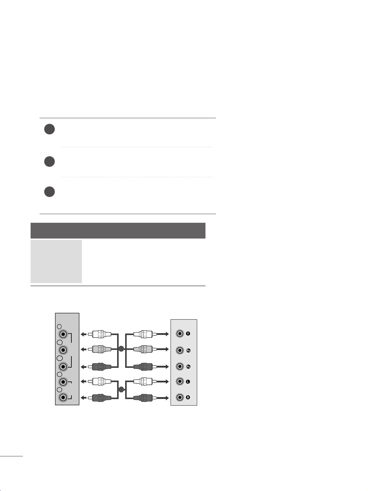
EXTERNAL EQUIPMENT SETUP
Connect the SET-TOP outputs to the
CC OOMMPPOONN EENNTT IINN
VV IIDDEE OO
sockets (Y P
B PR) on the set.
Connect the audio cable from the SET-TOP to
CC OO MMPP OO--
NN EENN TT IINN AAUU DD IIOO
sockets of the set.
Press the
IINNPP UUTT
button to select
CC oommppoonn eenn tt..
2
3
1
HD RECEIVER SETUP
■
To prevent the equipment damage, never plug in any power cords until you have finished connecting all equipment.
■
The image shown may be somewhat different from your set.
When connecting with a component cable
Signal
480i/576i
480p/576p
720p/1080i
10 8 0 p
Component
Yes
Yes
Yes
Yes
HDMI
No
Yes
Yes
Yes
VIDEO
COMPONENT
IN
AUDIO
Y
P
B
P
R
L
R
1
2
1133
EXTERNAL EQUIPMENT SETUP
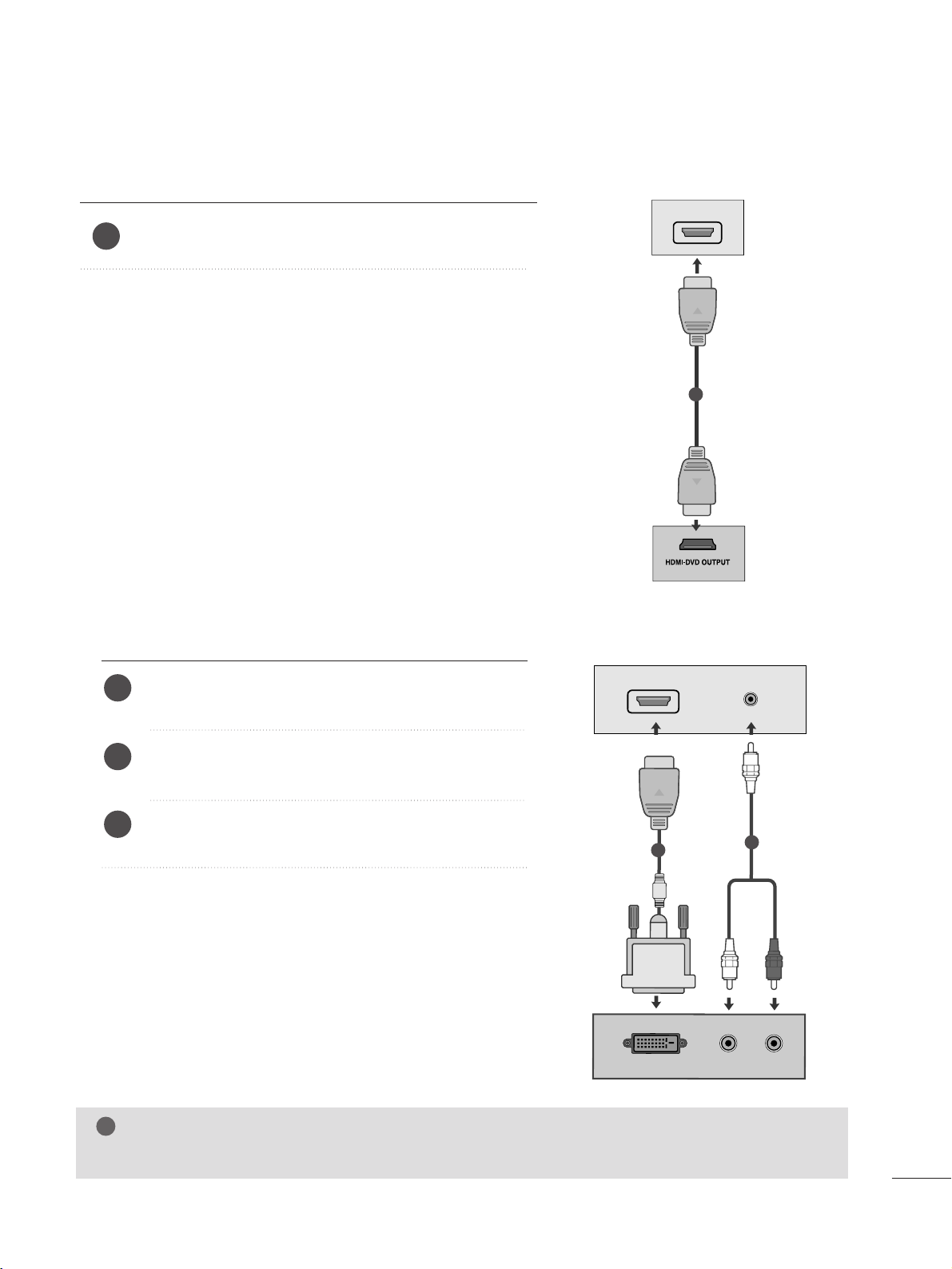
When connecting with a HDMI
Connect the HDMI output of the digital set-top box to the
HHDD MMII IINN
jack on the set.
1
Connect the digital set-top box to
HHDD MMII IINN
jack on
the set.
Connect the audio output of the digital set-top box to
the
AAUUDDII OO IINN (( RRGGBB//DDVVII))
jack on the set.
Turn on the digital set-top box. (Refer to the owner’s
manual for the digital set-top box.
)
2
3
1
When connecting with a HDMI to DVI cable
NOTE
!
G
HDMI Input does not support PC mode. If it is connected PC, the screen may not be displayed properly.
HDMI IN
AV 1 AV 2
1
DVI OUTPUT
AUDIO
RL
AUDIO IN
(RGB/DVI)
HDMI IN
1
2
1144
EXTERNAL EQUIPMENT SETUP
DVD SETUP
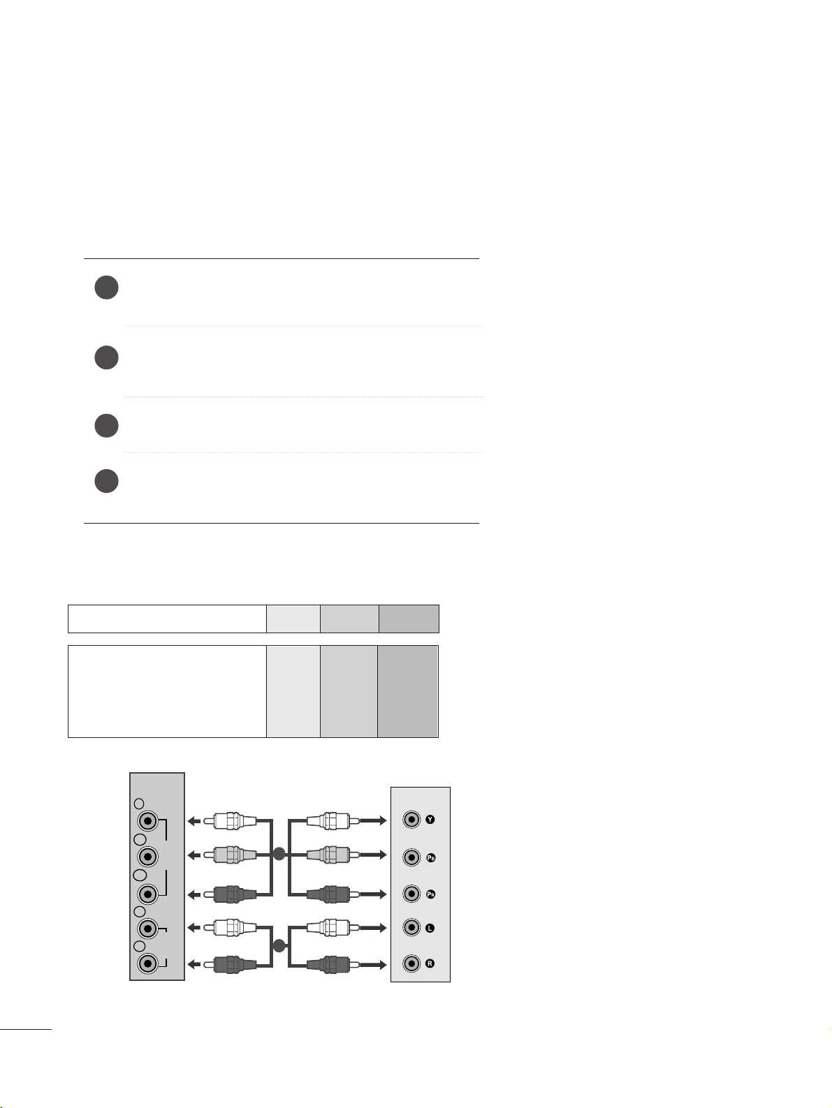
When connecting with a component cable
Component Input ports
To get better picture quality, connect a DVD player to the component input ports as shown below.
Component ports on the set
YPBP
R
Video output ports
on DVD player
Y
Y
Y
Y
P
B
B-Y
Cb
Pb
P
R
R-Y
Cr
Pr
Connect the video output sockets (Y P
B PR) of the DVD to
the
CC OO MMPPOO NN EENNTT IINN VVIIDDEEOO
sockets (Y P
B PR) of the set.
Connect the audio cable from the DVD to
CC OO MMPPOO NN EENNTT
IINN AA UUDD IIOO
sockets of the set.
Press the
IINNPP UUTT
button to select
CCoomm ppoonn ee nntt
.
Press the
PPLL AAYY
button on the DVD.
The DVD playback picture appears on the screen.
2
3
4
1
1
2
COMPONENT
IN
Y
P
B
VIDEO
P
R
L
AUDIO
R
1155
EXTERNAL EQUIPMENT SETUP
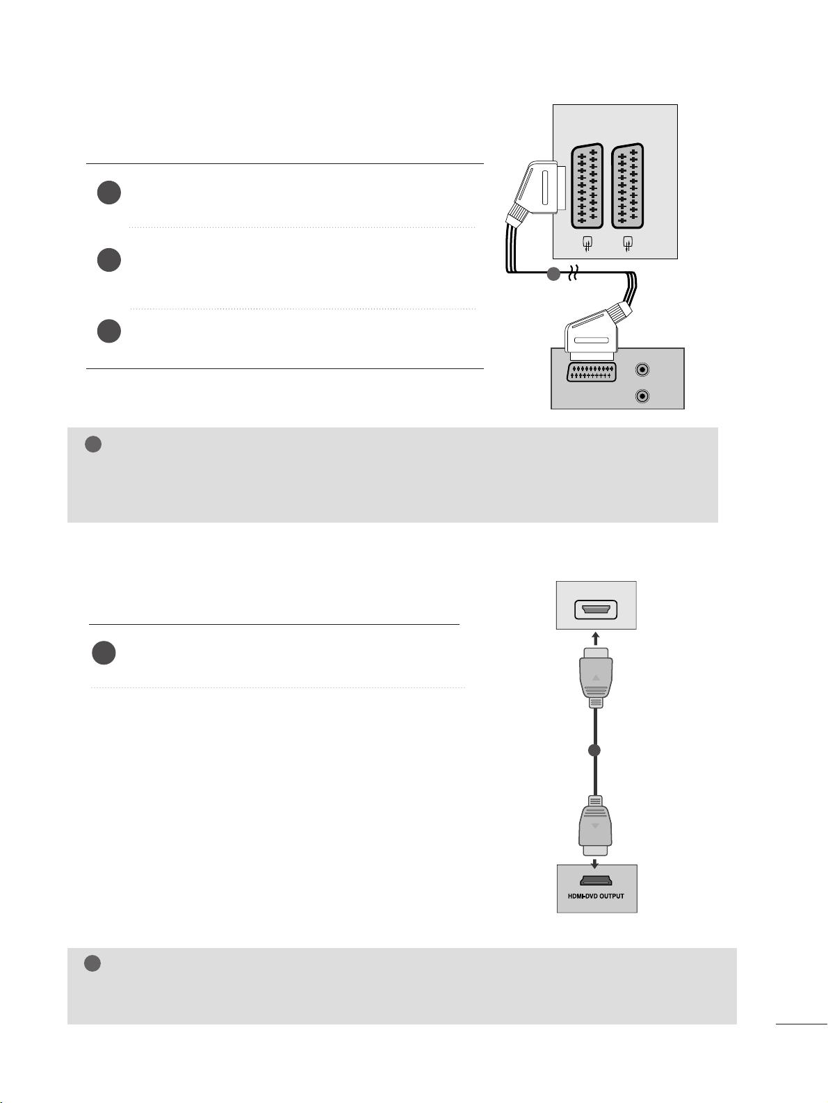
When connecting with a Euro Scart[DVD]
Connect the Euro scart socket of the DVD to the Euro scart
socket of the set.
Press the
IINNPP UUTT
button to select
AAVV 11
.
If connected to
AA VV 22
Euro scart socket, select
AA VV 22
input
source.
Press the
PPLL AAYY
button on the DVD.
The DVD playback picture appears on the screen.
2
3
1
When connecting HDMI cable
Connect the HDMI output of the DVD to the
HHDD MMII IINN
jack on the set.
1
G Set can receive the video and audio signal simultaneously by using a HDMI cable.
G If the DVD player does not support Auto HDMI, you need to set the DVD output resolution appropriately.
NOTE
!
NOTE
!
G Signal type RGB, i.e. the signals red, green and blue can only be selected for the Euro scart and the AV 1 can be
received. These signals are transmitted, for example, by a paid TV decoder, game machine or photo CD unit, etc.
G Please use shielded scart cable.
AUDIO
(L)
(R)
AUDIO/
VIDEO
AV 1 AV 2
1
HDMI IN
AV 1 AV 2
1
1166
EXTERNAL EQUIPMENT SETUP
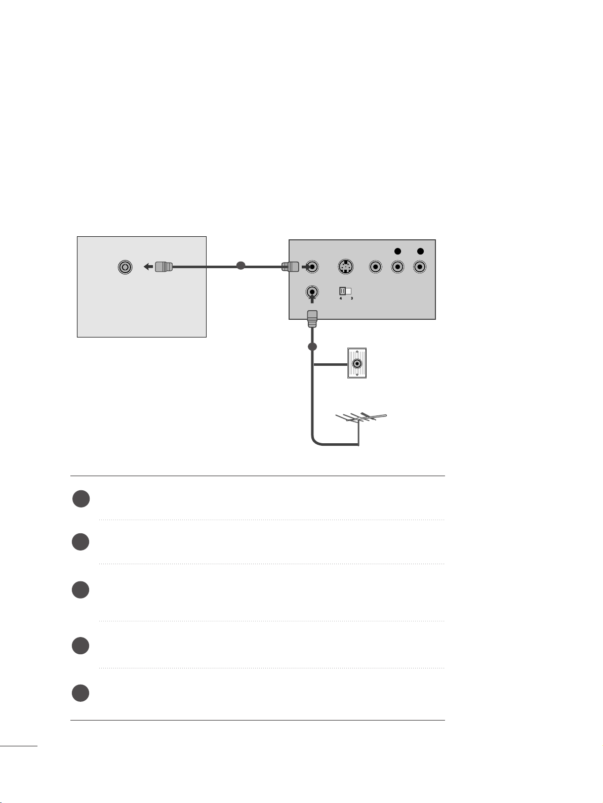
VCR SETUP
■
To avoid picture noise (interference), leave an adequate distance between the VCR and set.
■
Typically a still picture is shown on the VCR. If a user uses 4:3 picture format for a long time, an afterimage
may remain on the sides of the screen.
OUTPUT
SWITCH
ANT IN
R
S-VIDEO VIDEO
ANT OUT
L
ANTENNA/
CABLE IN
Wall Jack
Antenna
1
2
When connecting with an antenna
Connect the RF out socket of the VCR to the aerial socket of the set.
Connect the aerial cable to the RF aerial in socket of the VCR.
Store the VCR channel on a desired programme number using the ‘Manual
programme tuning’ section.
Select the programme number where the VCR channel is stored.
Press the
PPLL AAYY
button on the VCR.
1
2
3
4
5
1177
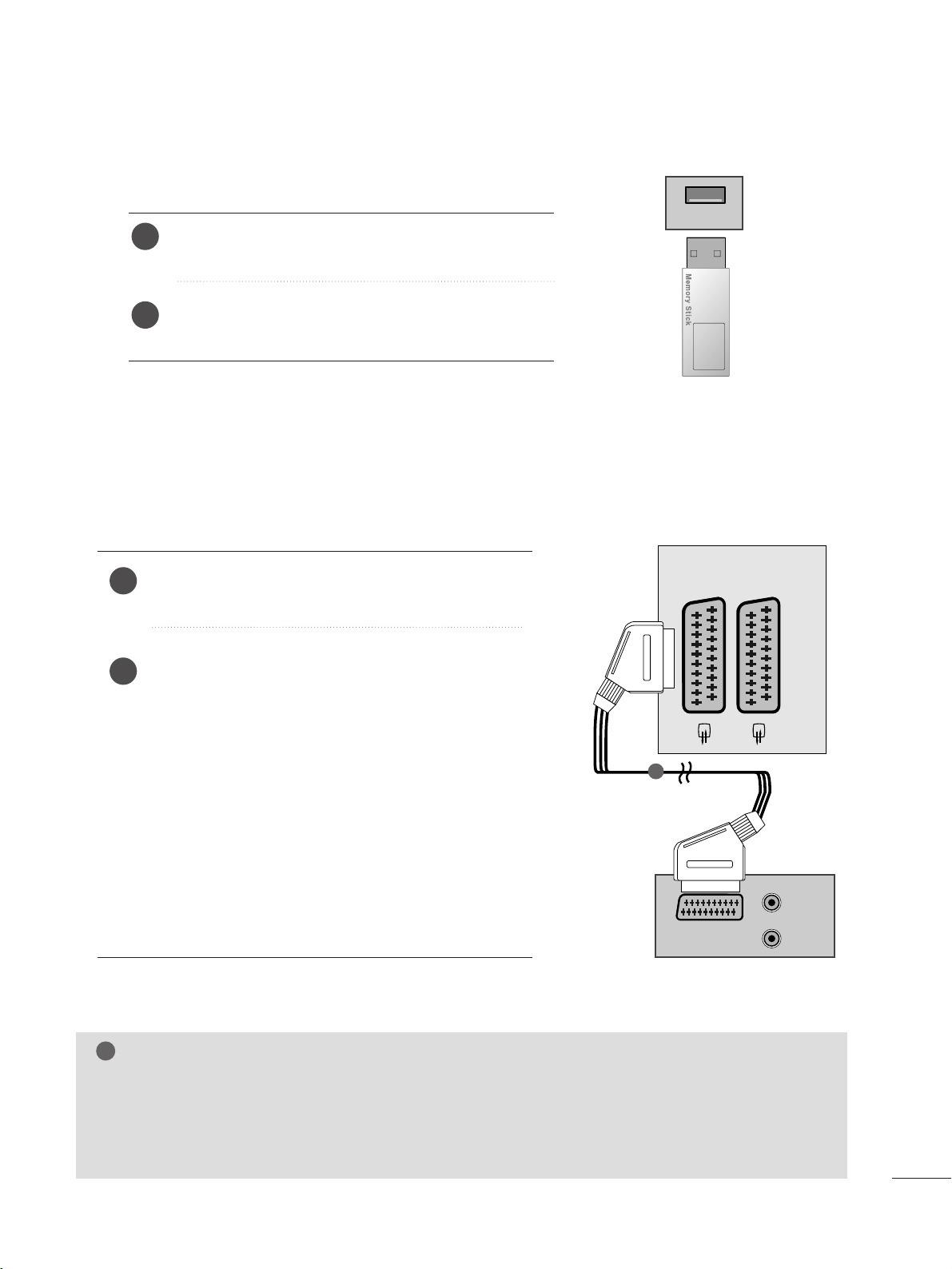
EXTERNAL EQUIPMENT SETUP
Connect the USB device to the
UUSS BB IINN
jacks on the
side of set.
After connecting the
UUSS BB IINN
jacks, you use the
UU SS BB
function. (
G
pp..8866
)
2
1
USB SETUP
USB IN
When connecting with a Euro Scart[VCR]
Connect the Euro scart socket of the VCR to the Euro
scart socket of the set.
Press the
PPLL AAYY
button on the VCR.
If your VCR outputs an AV switching signal via the Scart
lead, the set will auto switch to
AAVV 11
mode on start of
playback, but if you want to keep on watching in TV mode,
press the
D
//
E or NUMBER buttons.
If connected to
AA VV 22
Euro scart socket, select
AA VV 22
input
source.
Otherwise press the
IINNPP UUTT
button on the remote control
handset to select
AAVV 11
. The VCR playback picture appears
on the screen.
You can also record programmes received by the set on
video tape.
2
1
NOTE
!
G
Signal type RGB, i.e. the signals red, green and blue can only be selected for the Euro scart and the AV 1
can be received. These signals are transmitted, for example, by a paid TV decoder, game machine or photo
CD unit, etc.
G
Please use shielded scart cable.
AUDIO/
VIDEO
AV 1V 1 AV 2V 2
AUDIO
(L)
(R)
1
1188
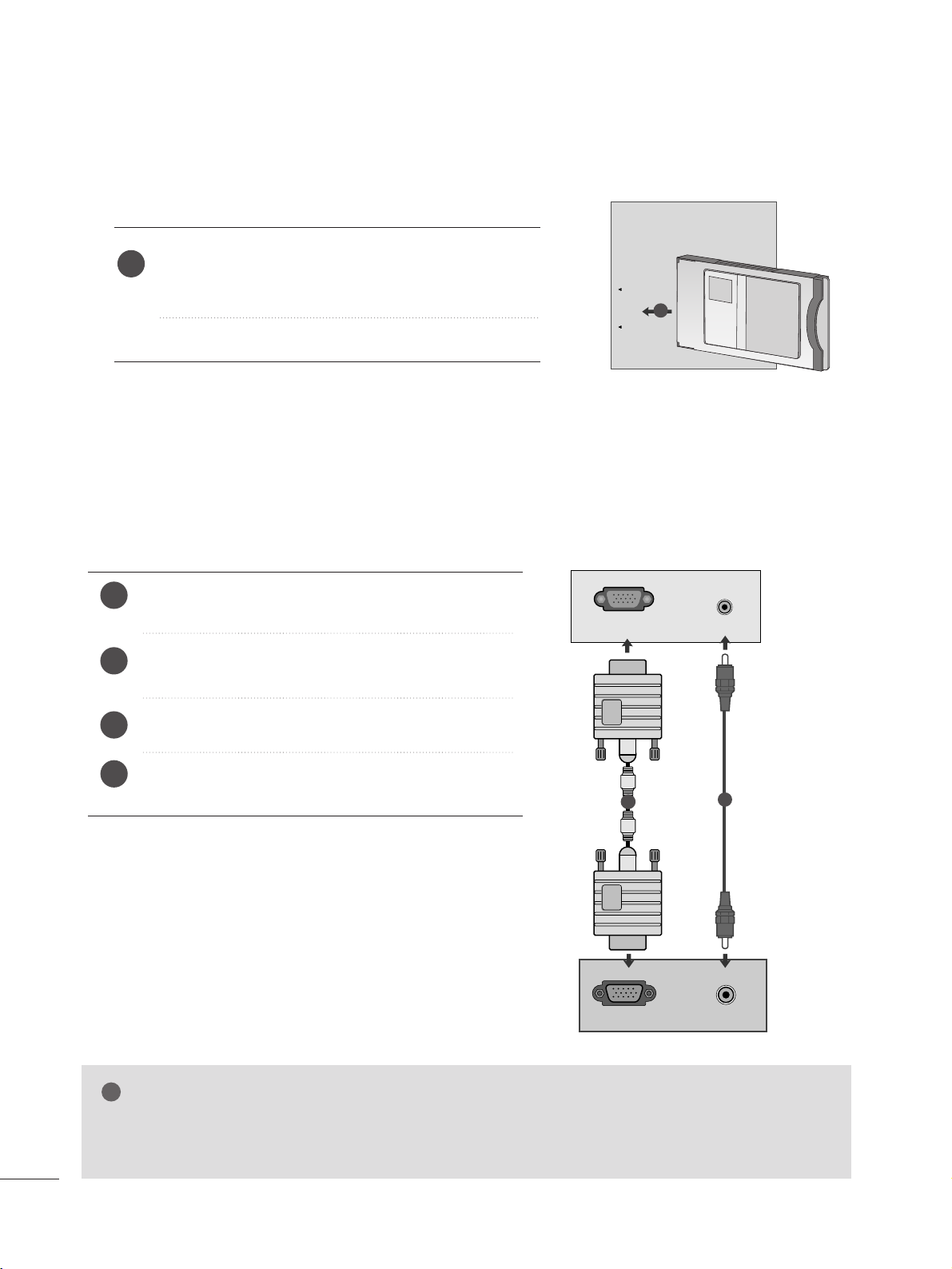
PC SETUP
This product provides Plug and Play capability, meaning that the PC adjusts automatically to the set's settings.
When connecting with a D-sub 15 pin cable
4
Connect the signal cable from the monitor output socket of
the PERSONAL COMPUTER to the PC input socket of the set.
Connect the audio cable from the PC to the
AA UUDD II OO IINN
((RRGGBB//DDVVII))
sockets of the set.
Press the INPUT button to select
RR GGBB
.
Switch on the PC, and the PC screen appears on the set.
The set can be operated as a PC monitor.
2
3
1
AV 1 AV 2
RGB IN (PC)
RGB OUTPUT
AUDIO
AUDIO IN
(RGB/DVI)
1
2
NOTE
!
G
You must use shielded signal interface cables (D sub 15 pin cable, DVI cable) with ferrite cores to maintain
standard compliance for the product.
EXTERNAL EQUIPMENT SETUP
Insert the CI Module to
PPCCMM CC II AA
(Personal Computer
Memory Card International Association)
CC AARRDD SSLL OO TT
of set as shown.
For further information, see p. 37.
1
INSERTION OF CI MODULE
PCMCIA
CARD SLOT
TVTVTV
-- TT oo vviieeww tthh ee ssccrraammbbll eedd ((ppaaii dd)) sseerr vviicceess iinn ddiiggiittaall TT VV mmooddee ..
-- TThhii ss ffeeaattuu rr ee iiss nnoott aavv aaiillaabbll ee iinn aall ll ccoouunn ttrr iieess ..
1
1199
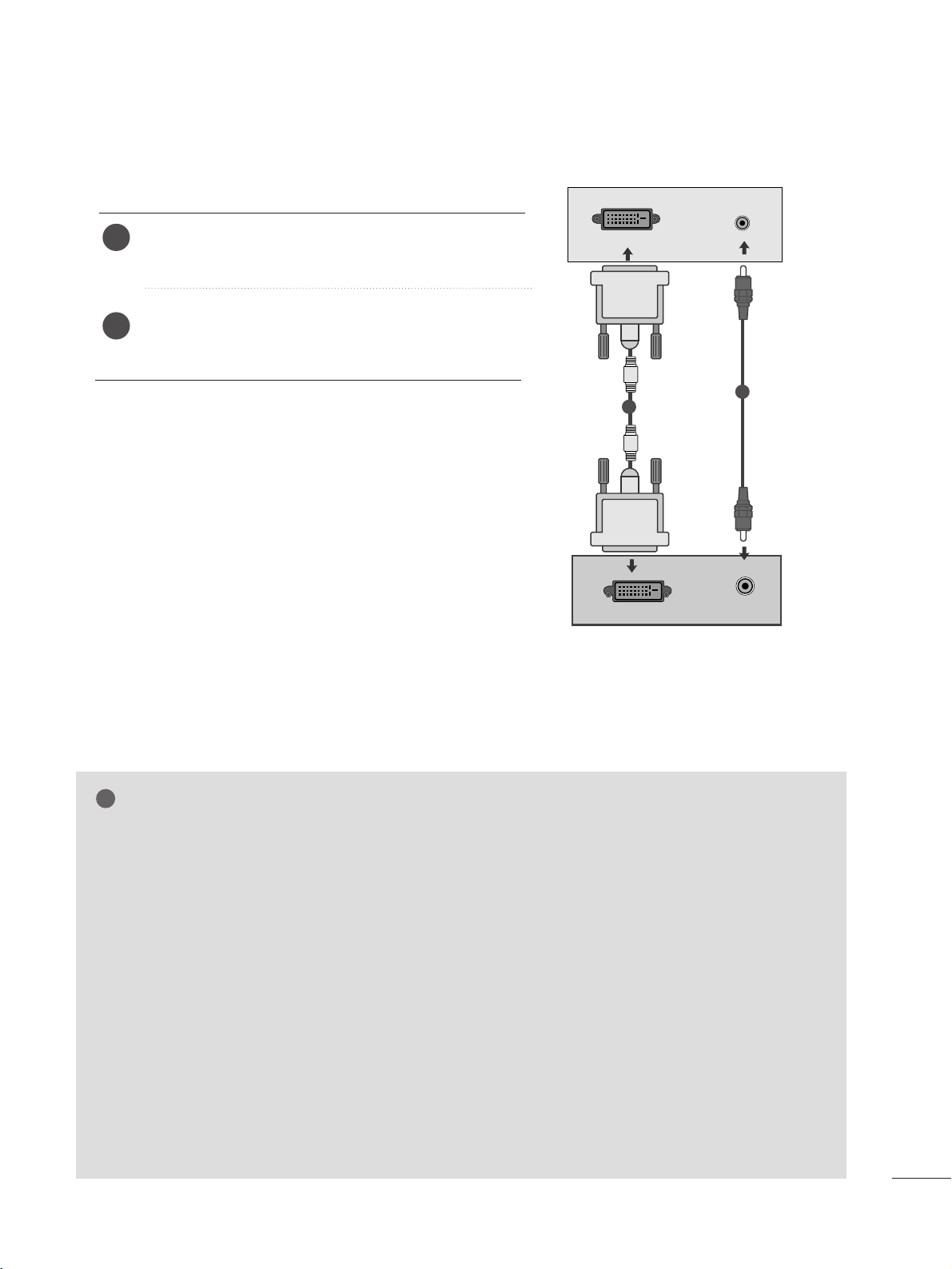
EXTERNAL EQUIPMENT SETUP
When connecting with a DVI cable
Connect the DVI output of the PC to the
DDVVII--DD II NN
jack on the set.
Connect the audio cable from the PC to the
AA UU DDII OO
IINN (( RRGG BB //DDVVII ))
sockets of the set.
2
1
NOTE
!
G
If the set is cold, there may be a small “flicker” when the
set is switched on. This is normal, there is nothing wrong
with the set.
G
If possible, use the 1360 x 768 @ 60 Hz video mode to
obtain the best image quality for your LCD monitor. If
used with other resolutions, some scaled or processed
pictures may appear on the screen. The set has been
preadjusted to the mode 1360 x 768 @ 60 Hz.
((MM119977WWDDPP))
G
If possible, use the 1920 x 1080 @ 60 Hz video mode
to obtain the best image quality for your LCD monitor. If
used with other resolutions, some scaled or processed
pictures may appear on the screen. The set has been
preadjusted to the mode 1920 x 1080 @ 60 Hz.
((MM222277WWDDPP//MM223377WWDDPP))
G
Some dot defects may appear on the screen, like Red,
Green or Blue spots. However, this will have no impact or
effect on the monitor performance.
G
Do not press the LCD screen with your finger for a long
time as this may produce some temporary distortion
effects on the screen.
G
Avoid keeping a fixed image on the set’s screen for prolonged periods of time. The fixed image may become
permanently imprinted on the screen; use a screen saver
when possible.
AUDIO
DVI OUTPUT
DVI-D (PC)
AUDIO IN
(RGB/DVI)
1
2
2200
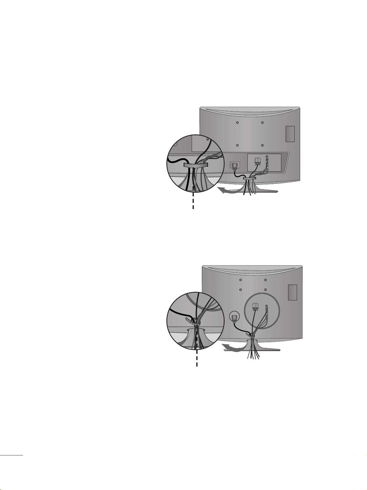
EXTERNAL EQUIPMENT SETUP
Tie cables together with a cable management as
shown in the illustration.
Cable management
Tie cables together with a cable tie as shown in the
illustration.
Cable tie
<<MM11 9977 WWDD PP//MM 2222 77WWDDPP >>
<<MM22 33 77WWDDPP >>
BACK COVER FOR WIRE ARRANGEMENT
2211
EXTERNAL EQUIPMENT SETUP
RGB/DVI[PC]
HDMI[DTV] (Not Support PC)
60
60
50
50
60
60
60
60
50
24
30
50
60
60
31.469
31.5
31.25
37.5
44.96
45
33.72
33.75
28.125
27
33.75
56.25
67.43
67.5
Resolution
720x480/60p
720x576/50p
1280x720/60p
1280x720/50p
Horizontal
Frequency(kHz)
Vertical
Frequency(Hz)
1920x1080/60i
1920x1080/50i
1920x1080/24p
1920x1080/30p
1920x1080/50p
1920x1080/60p
<M197WDP>
Resolution
640x480
800x600
1024x768
Horizontal
Frequency(kHz)
Vertical
Frequency(Hz)
60
75
60
75
60
75
60
60
60
31.469
37.500
37.879
46.875
48.363
60.123
47.776
49.306
47.712
1360x768
1280x768
<M227WDP/M237WDP>
Resolution
640x480
800x600
720x400
1024x768
Horizontal
Frequency(kHz)
Vertical
Frequency(Hz)
70
60
75
60
75
60
75
75
60
75
60
60
60
60
31.468
31.469
37.500
37.879
46.875
48.363
60.123
67.500
63.981
79.976
64.674
65.290
75.000
66.587
1280x1024
1152x864
1680x1050
1920x1080
1600x1200
1280x800
2222
WATCHING TV /PROGRAMME CONTROL
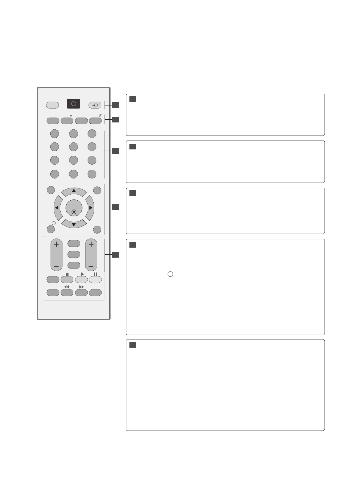
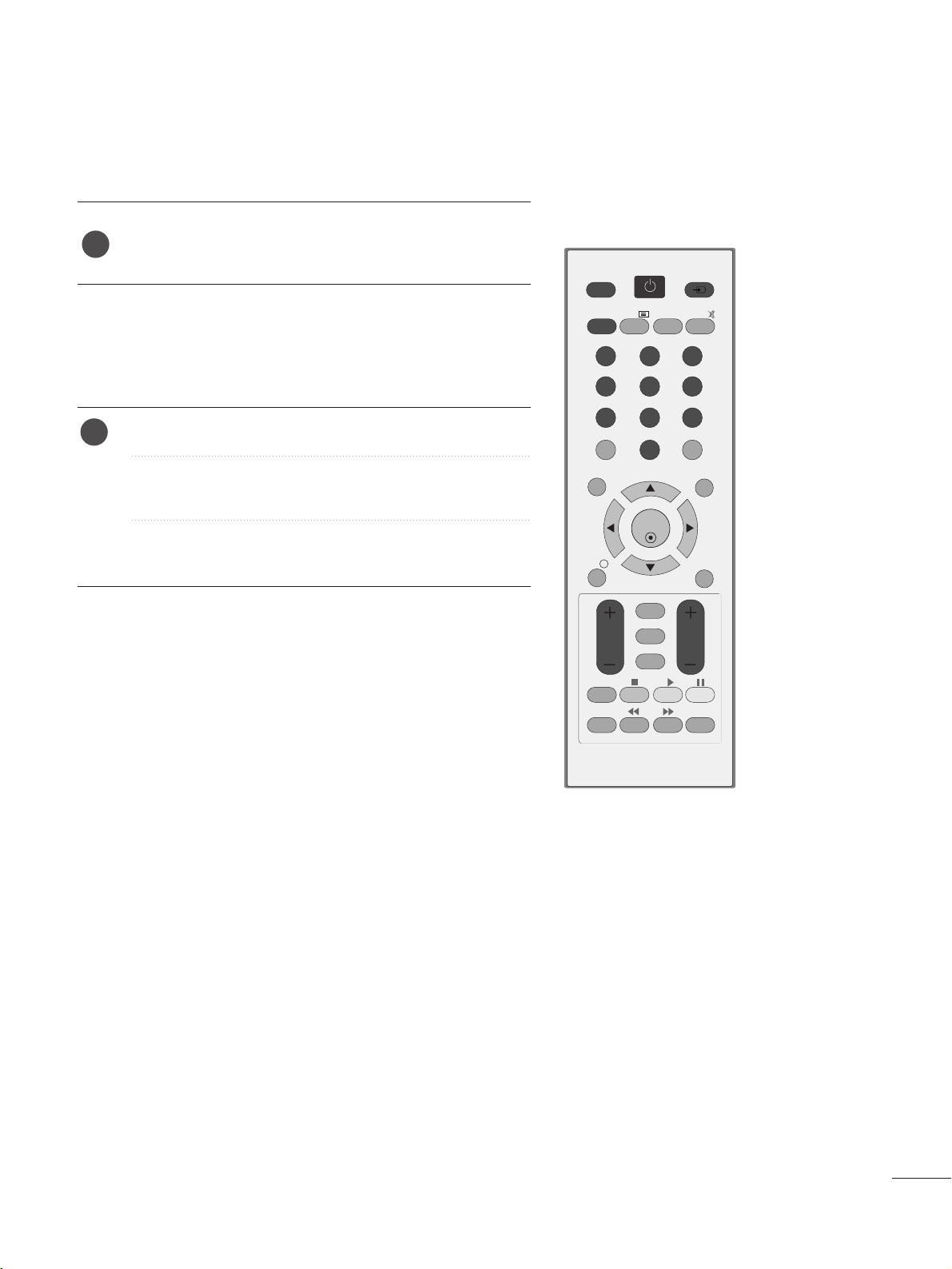
REMOTE CONTROL KEY FUNCTIONS
When using the remote control, aim it at the remote control sensor on the set.
OK
MENU EXIT
GUIDE
123
456
789
0
Q.VIEW
LIST
TV/PC INPUT
POWER
VOL PR
I/II
MUTE
TEXT
RETURN
FAV
INFO
i
TV/RADIO
*
Q.MENU
T.OPT MARK
SUBTITLE
POWER
TV/PC
INPUT
Switches the set on or off.
Selects TV or PC mode.
External input mode rotates in regular sequence.
TV/RADIO
I/II
MUTE
Selects Radio or TV channel.
Selects the sound output.(Refer to the p.68,69)
Switches the sound on or off.
0~9 number
button
LIST
Q.VIEW
Selects a programme.
Selects numbered items in a menu.
Displays the programme table.(Refer to the p.38)
Returns to the previously viewed programme.
MENU
EXIT
INFO i
GUIDE
THUMBSTICK
(Up/Down/Left/Right)
OK
Selects a menu. (Refer to the p.27)
Clears all on-screen displays.
Shows the present screen information.
Shows programme schedule.(Refer to the p.39~41 )
Allows you to navigate the on-screen menus and adjust
the system settings to your preference.
Accepts your selection or displays the current mode.
VOLUME UP
/DOWN
RETURN
*
FAV
Programme
UP/DOWN
Adjusts the volume.
Allows the user to move back one step in an interactive application, EPG or other user interaction function.
No function
Displays the selected favourite programme.(Refer to the p.38)
Selects a programme.
11
11
22
33
44
55
22
33
44
55
2233
WATCHING TV /PROGRAMME CONTROL
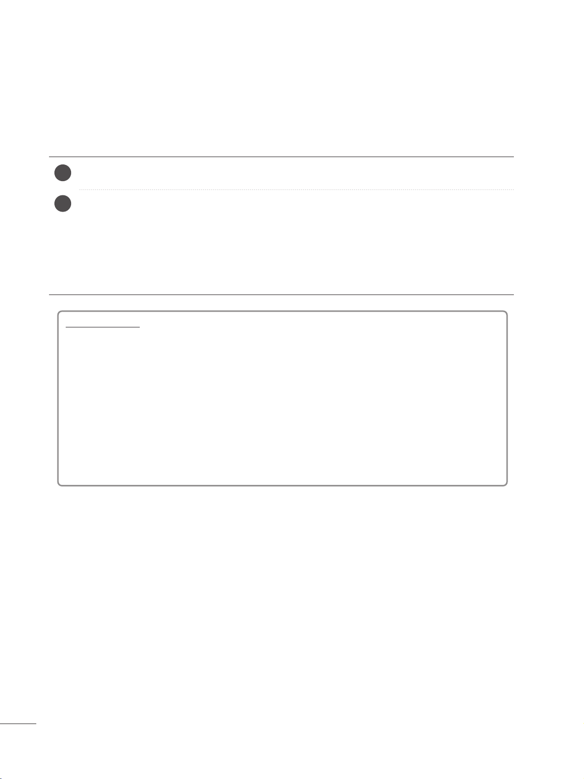
Installing Batteries
■
Open the battery compartment cover on the back and install the batteries matching correct polarity (+ with +, - with -).
■
Install two 1.5 V AAA batteries. Don’t mix old or used batteries with new
ones.
■
Close cover.
■
To remove the batteries, perform the installation actions in reverse.
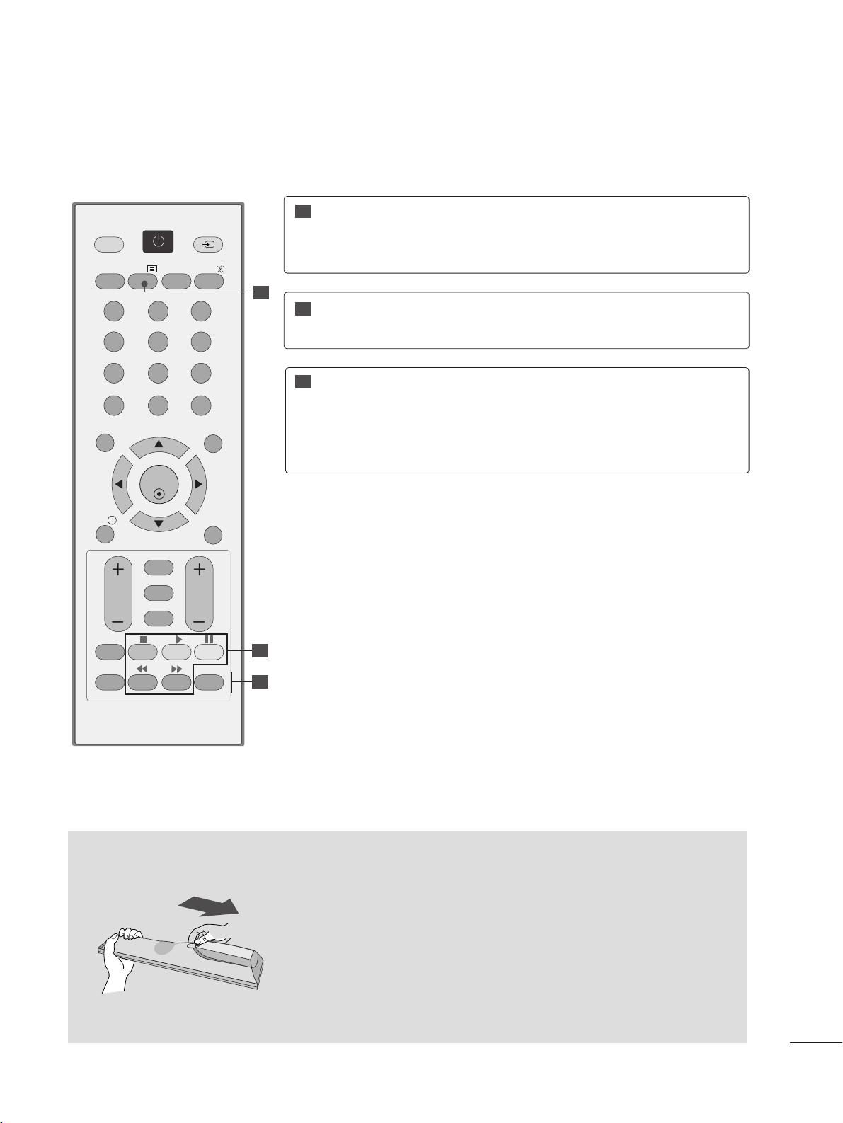
USB Menu
control buttons
Controls USB menu (Photo List and Music
List)
(Refer to the p.86)
TELETEXT
BUTTONS
These buttons are used for teletext.
For further details, see the ‘Teletext’ section.
(Refer to the p.94~96)
11
22
33
Q.MENU
MARK
Select the desired quick menu source.
(Refer to the p.26)
Check and un-check programmes in the recorded set
menu.
OK
MENU EXIT
GUIDE
123
456
789
0
Q.VIEW
LIST
TV/PC INPUT
POWER
VOL PR
I/II
MUTE
TEXT
RETURN
FAV
INFO
i
TV/RADIO
*
Q.MENU
T.OPT MARK
SUBTITLE
11
22
33
2244
WATCHING TV /PROGRAMME CONTROL
TURNING ON THE TV
- When your TV is turned on, you will be able to use its features.
Firstly,connect the power cord correctly and check the main power( r / I )on the TV.
SSeett IIDD :: OOffff
In standby mode to turn TV on, press the INPUT or PR
D
//
E
button on the TV or press the POWER button on the
remote control and the TV will switch on.
SSeett IIDD :: OOnn
In standby mode to turn TV on,pr ss the INPUT or PR
D
//
E
button on the TV or press the POWER, INPUT, PR
D
//
E
or NUMBER button on the remote control and the TV will switch on.
2
1
Initializing setup
Note:
a. If you close without completing the initial setting, the Initial Setting menu can be displayed again.
b. Press the RETURN button to change the current OSD to the previous OSD.
c. For those countries without confirmed DTV broadcasting standards, some DTV featur s might not work,
depending on the DTV broadcasting environment.
d. "
HHoommee UUssee
” mode is the optimal setting for home environments, and is the TV's default mode.
e. "
SSttoorree DDeemmoo
"mode is the optimal setting for store environments. If a user modifies image quality data, “
SSttoorree
DDeemmoo
” mode initializes the product to the image quality set by us after a certain period of time.
f. The mode (
HHoommee UUssee, SSttoorree DDeemmoo
) can be changed by executing
MMooddee SSeettttiinngg
in the
OOPPTTIIOONN
menu.
If the OSD (On Screen Display) is displayed on the screen after turning on the TV, you can adjust
the
LLaann gguuaa ggee, MMooddee SSeettttiinngg, CC oouu nnttrryy, AA uuttoo tt uunniinn gg
.
2255
WATCHING TV /PROGRAMME CONTROL
OK
MENU EXIT
GUIDE
123
456
789
0
Q.VIEW
LIST
TV/PC INPUT
POWER
VOL PR
I/II
MUTE
TEXT
RETURN
FAV
INFO
i
TV/RADIO
*
Q.MENU
T.OPT MARK
SUBTITLE
PROGRAMME SELECTION
Press the
PPRR ++ or--
or NUMBER buttons to select a pro-
gramme number.
1
VOLUME ADJUSTMENT
Press the VOL
++ or--
button to adjust the volume.
If you want to switch the sound off, press the MUTE
button.
You can cancel this function by pressing the MUTE,
VOL
++ or--
, or I/II button.
1
2266
WATCHING TV /PROGRAMME CONTROL
• Press the RETURN button to move to the previous menu screen.
•
AA ssppee cc tt RR aattiioo
: Selects your desired picture format.
For Zoom Setting, select 14:9, Zoom and Cinema
Zoom in Ratio Menu. After completing Zoom Setting,
the display goes back to Q.Menu.
•
PPii cc ttuurree MMooddee
: Selects your desired Picture Mode.
•
SSoouunn dd MMooddee
: It is a feature to automatically set the
sound combination which it deems the best for the
images being watched. Selects your desired Sound
Mode.
•
AA uuddii oo
: Selects the sound output.
•
SSll eeeepp TTiimm eerr
: Sets the sleep timer.
•
UUSSBB EEjjeecctt
: Selects “USB Eject” in order to eject USB
device.
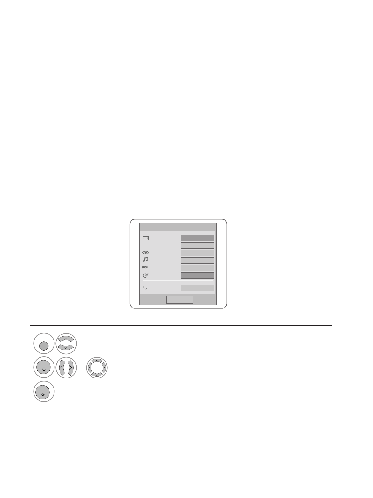
QUICK MENU
Display each menu.
Select your desired Source.
Your TV's OSD (On Screen Display) may differ slightly from that shown in this manual.
Q.Menu (Quick Menu) is a menu of features which users might use frequently.
1
Q. MENU
3
2
OK
OK
or
QQ .. MMee nn uu
CCll oossee
11 66::99
ZZ oooo mm SS ee tt tt iinn gg
SSttaann dd aa rr dd
SSttaann dd aa rr dd
LL ++ RR
OOffff
EEjj ee cctt
Aspect Ratio
Picture Mode
Sound Mode
Audio
Sleep Timer
USB Eject
2277
WATCHING TV /PROGRAMME CONTROL
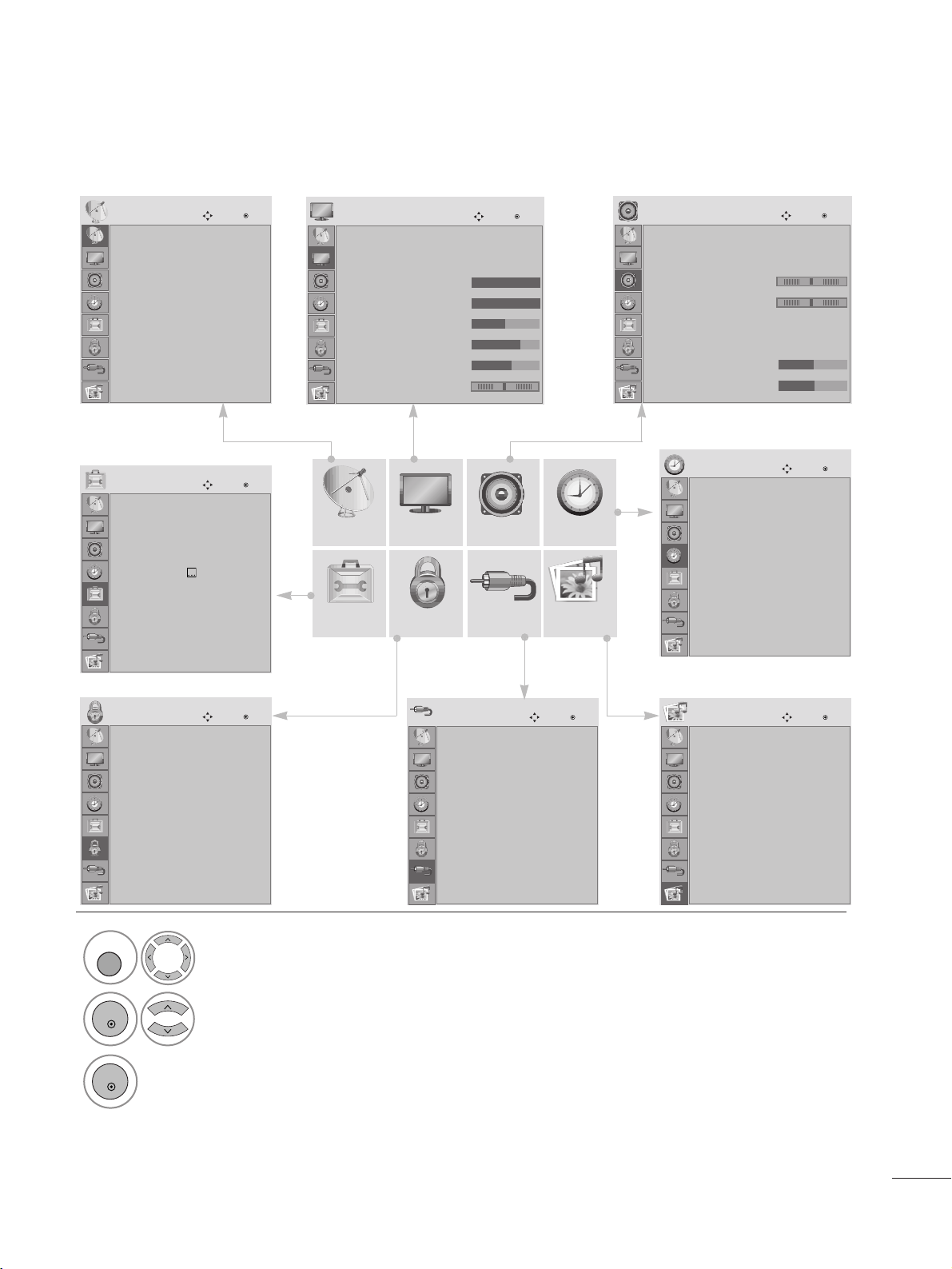
ON SCREEN MENUS SELECTION AND ADJUSTMENT
Your set's OSD (On Screen Display)may differ slightly from what is shown in this manual.
SETUP
OPTION LOCK INPUT USB
AUDIO TIME
PICTURE
1
Display each menu.
2
Select a menu item.
3
Move to the pop up menu.
MENU
OK
OK
• Press the MENU or EXIT button to close the menu window.
• Press the RETURN button to move to the previous menu screen.
Auto tuning
Manual tuning
Programme Edit
Software Update : On
Diagnostics
CI Information
SETUP
Move
OK
Clock
Off Time : Off
On Time : Off
Sleep Timer : Off
Auto Off : On
TIME
Move
OK
Menu Language : English
Audio Language : English
Subtitle Language : English
Hard of Hearing
()
: Off
Data Service : MHEG
Country : UK
Input Label
Key Lock : Off
OPTION
Move
OK
Lock System : Off
Set Password
Block Programme
Parental Guidance : Off
Input Block
LOCK
Move
OK
Antenna
AV 1
AV 2
Component
RGB
HDMI
DVI
INPUT
Move
OK
Photo List
Music List
USB
Move
OK
Auto Volume : Off
Clear Voice II : Off
• Level 3
Balance 0
Sound Mode : Standard
• SRS TruSurround XT : Off
• Treble 50
• Bass 50
AUDIO
Move
OK
-+
LR
E
E
Aspect Ratio : 16:9
Picture Mode : Vivid
• Backlight 100
• Contrast 100
• Brightness 50
• Sharpness 70
• Colour 60
• Tint 0
PICTURE
Move
OK
E
RG
2288
WATCHING TV /PROGRAMME CONTROL
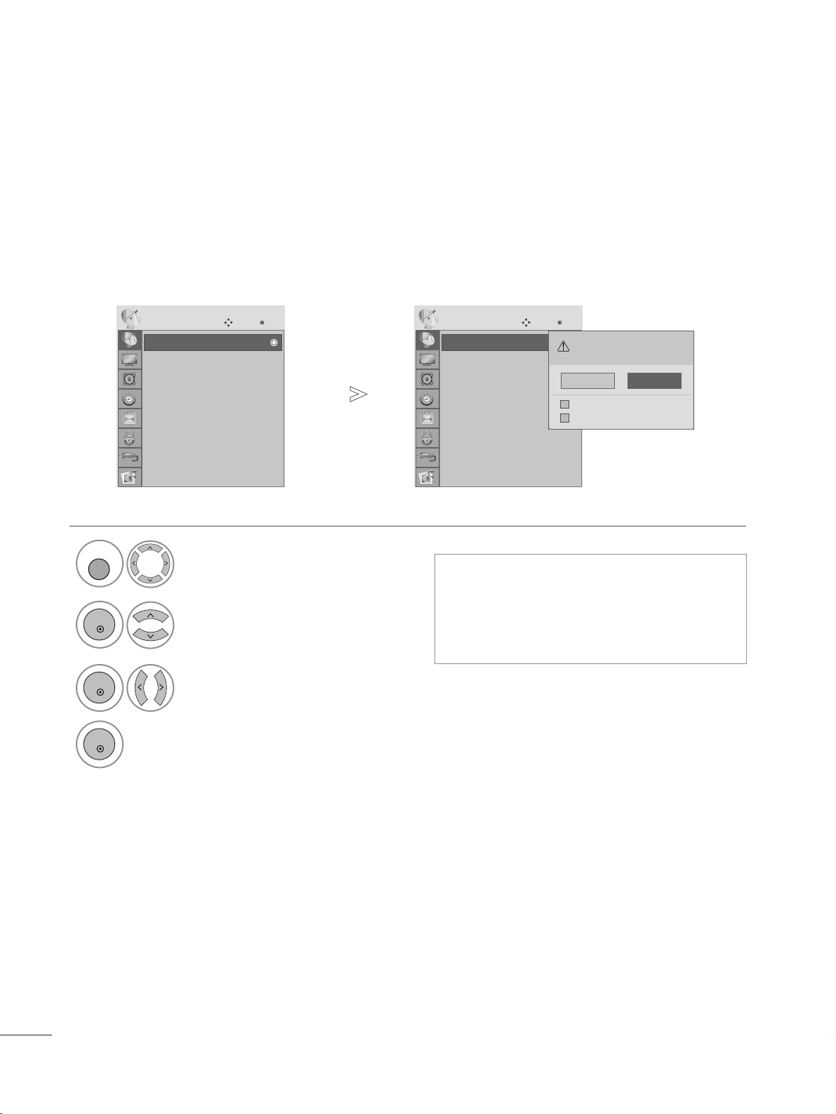
Use this to automatically find and store all available programmes.
When you start auto programming in digital mode, all previously stored service information will be deleted.
AUTO PROGRAMME TUNING
• Use NUMBER buttons to input a 4-digit
password in Lock System ‘On’.
• If you wish to keep on auto tuning, select
YES using the
F G
button. Then, press the
OK button. Otherwise, select NO.
Select
SSEE TTUUPP
.
2
Select
AA uuttoo TTuu nnii nngg
.
3
Select
YY ee ss
.
4
Run Auto tuning.
1
•
Press the MENU or EXIT button to close the menu window.
• Press the RETURN button to move to the previous menu screen.
Auto tuning
Manual tuning
Programme Edit
Software Update : On
Diagnostics
CI Information
SETUP
Move
OK
AAuu tt oo ttuunniinngg
Auto tuning
Manual tuning
Programme Edit
Software Update : On
Diagnostics
CI Information
SETUP
Move
OK
AAuu tt oo ttuunniinngg
All service-information will be updated.
Continue?
SECAM L Search
Yes No
Automatic Numbering
VV
MENU
OK
OK
OK
 Loading...