

LG M237WD-PM Owner’s Manual

Make sure to read the Safety Precautions before
using the product.
Keep the User's Guide(CD) in an accessible place
for furture reference.
See the label attached on the product and give the
information to your dealer when you ask for service.
OWNER’S MANUAL
MM223377WWDD
1
PREPARATION
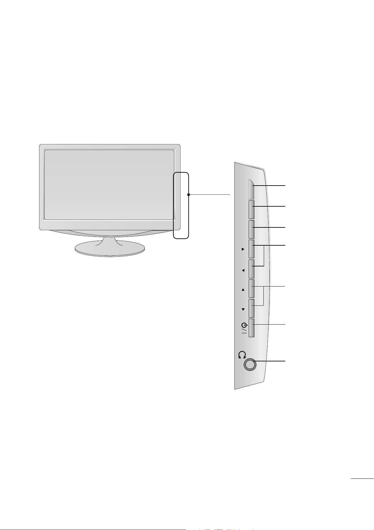
FRONT PANEL CONTROLS
■
This is a simplified representation of the front panel. The image shown may be somewhat different from your
set.
CHANNEL
Buttons
VOLUME
Buttons
MENU
Button
ENTER
Button
INPUT
Button
Power
Button
Headphone
Output
INPUT
MENU
VOL CHENTER
2
PREPARATION
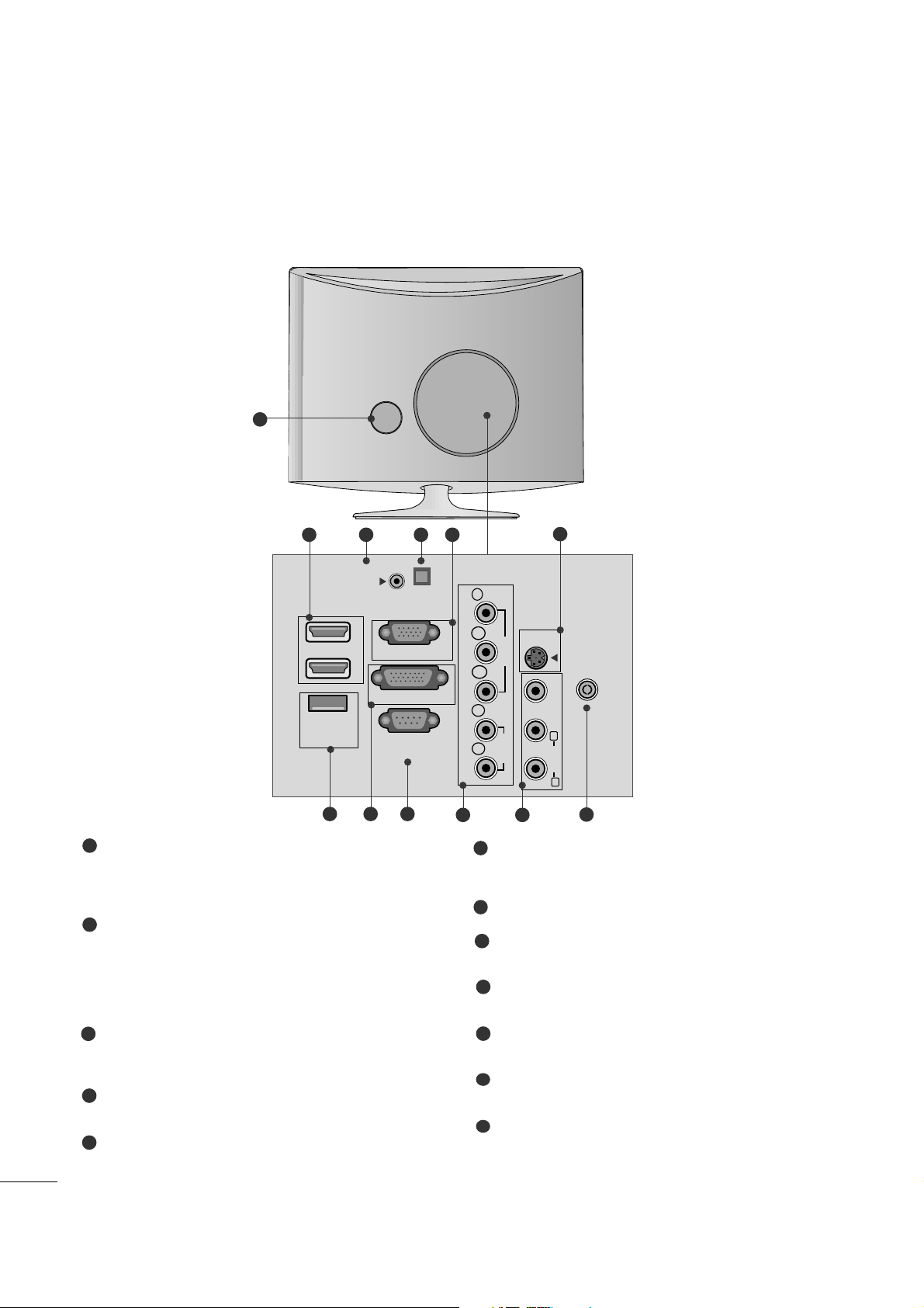
BACK PANEL INFORMATION
■
This is a simplified representation of the back panel. The image shown may be somewhat different from your
set.
2
9
10 11
1
87
12
5
6
3 4
Power Cord Socket
This set operates on AC power. The voltage is indicated on the Specifications page. Never attempt to
operate the set on DC power.
HDMI Input
High definition inputs. These two inputs accept TV
Video, not PC Video. They also accept TV Video from
a DVI connection when using an adapter. The HDMI
inputs support video and audio. When using an
adapter for DVI, they only accept video.
RGB/DVI Audio Input
This is the audio input for the RGB and DVI-D video
inputs.
Optical Digital Audio Out
Use this to export audio to an external amplifer.
RGB INPUT (PC)
Analog PC input. Also known as VGA.
S-Video Input
Standard definition (480i), but better quality than
standard A/V input.
SERVICE ONLY PORT
DVI-D Input
Digital PC input.
RS-232C IN (CONTROL & SERVICE) PORT
Serial port used for external control or service.
Component Input
High definition analog input.
Audio/Video Input
Standard definition input.
Antenna Input
Connect over-the-air or cable signals to this jack.
1
2
3
4
5
7
6
8
9
10
11
12
HDMI IN
SERVICE
ONLY
AUDIO IN
(RGB/DVI)
1
RGB IN (PC)
2
DVI-D IN (PC)
RS-232C IN
(CONTROL & SERVICE)
OPTICAL
DIGITAL
AUDIO OUT
COMPONENTINAV-IN
Y
P
B
VIDEO
P
R
L
AUDIO
R
S-VIDEO
ANTENNA/
CABLE IN
VIDEO
(MONO)
L
AUDIO
R
3
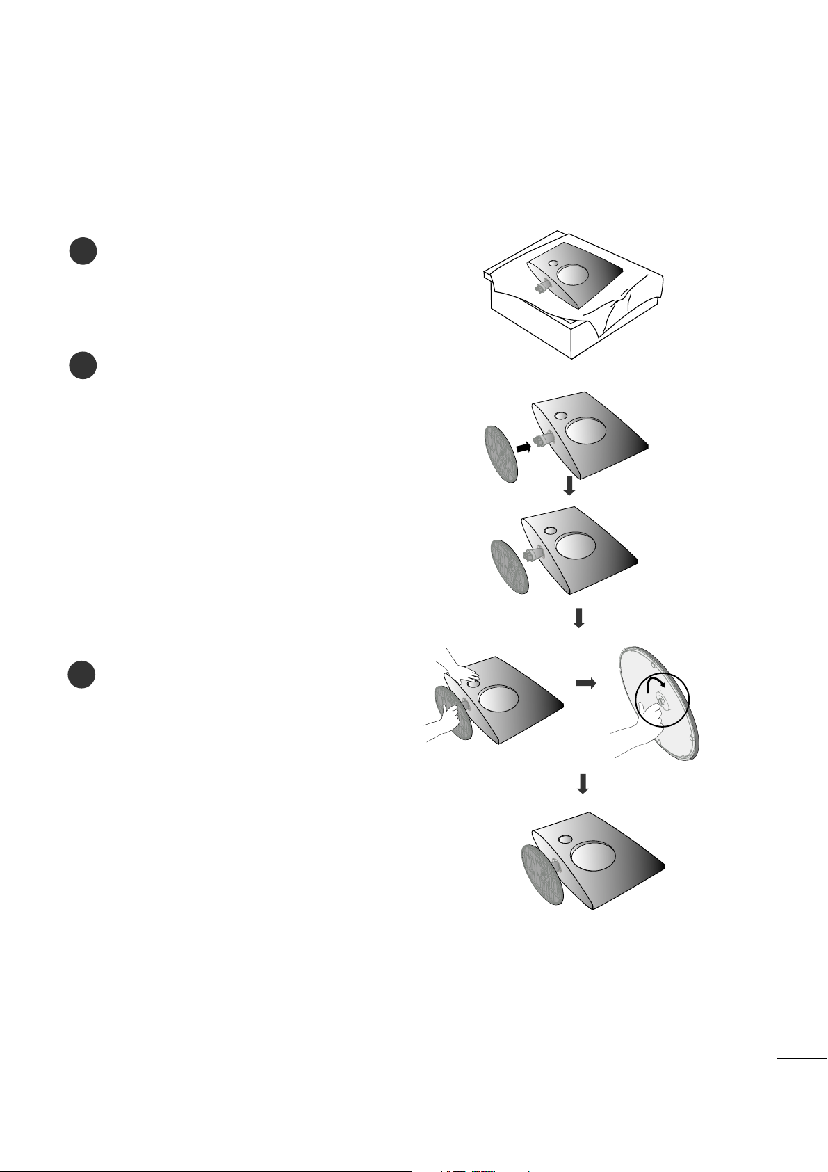
PREPARATION
STAND INSTALLATION
■
The image shown may be somewhat different from your set.
1
2
3
Carefully place the product screen side down on a
cushioned surface that will protect product and
screen from damage.
Insert the
sstt aanndd bbaassee
into the product
Attach the monitor to the Stand Base by turning
the screw to the right.
* Turn the screw by using the screw handle
Screw
4
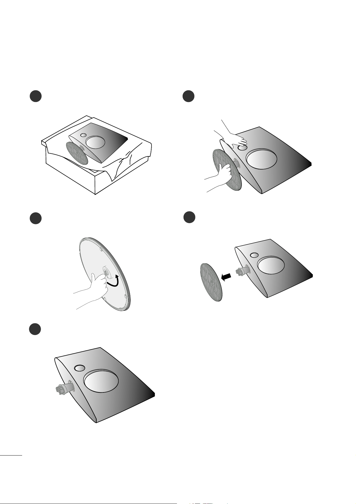
PREPARATION
DETACHING STAND
1
2
3
Place the set screen side down on a cushion or
soft cloth.
Detach the monitor from the Stand Base by
turning the screw to the left.
Turn the screw by using the screw handle
4
Pull the stand base.
5
■
The image shown may be somewhat different from your monitor.
5
PREPARATION
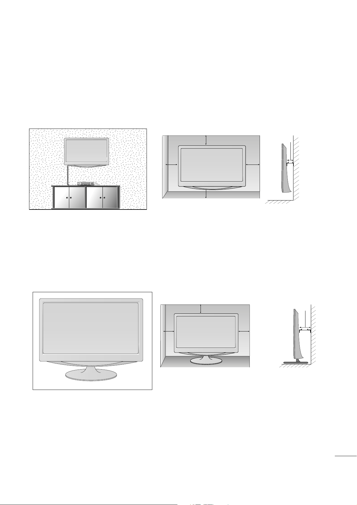
DESKTOP PEDESTAL INSTALLATION
For proper ventilation, allow a clearance of 4 inches on each side and from the wall.
4 inches
4 inches
4 inches
4 inches
WALL MOUNT: HORIZONTAL INSTALLATION
For proper ventilation, allow a clearance of 4 inches on each side and from the wall. Follow the instructions
included with the wall mount.
4 inches
4 inches
4 inches 4 inches
4 inches
6
PREPARATION
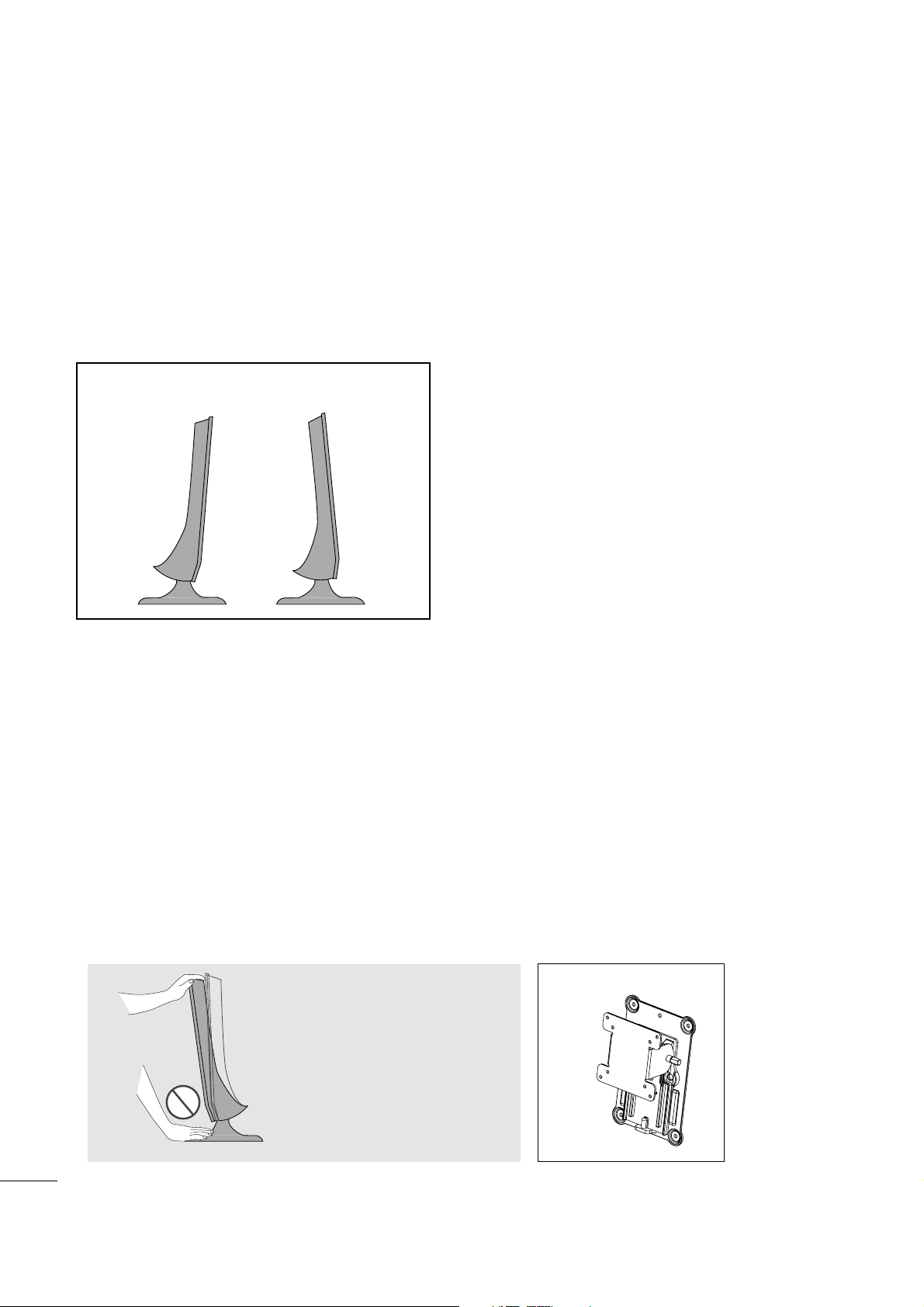
POSITIONING YOUR DISPLAY
■
The image shown may be somewhat different from your set.
Adjust the position of the panel in various ways for maximum comfort.
•• TTiill tt rraannggee
LOCATION
Position your set so that no bright light or sunlight falls directly onto the screen. Care should be taken not to
expose the set to any unnecessary vibration, moisture, dust or heat. Also, ensure that the set is placed in a position to allow a free flow of air. Do not cover the ventilation openings on the back cover.
If you intend to mount the set to a wall, attach the wall mounting interface (optional parts) to the back of the set.
When you install the set using the wall mounting interface (optional parts), attach it carefully so it will not drop.
- Be sure to use screws and a wall mount that meet VESA standards.
- Using screws longer than those recommended might damage the product.
- Using screws that do not meet VESA standards might either damage the product or result in it coming away from
the wall. We will not be held responsible for any damage resulting from failure to follow these instructions.
< Screw Mounting Interface Dimension >
* 75mm x 75mm hole spacing
* Wall mount interface(LG) : RW120
-6°~ -2
°
12°~ 18
°
WW aa rrnnii nngg::
When adjusting the angle of the
screen, do not put your finger(s)in
between the head of the monitor
and the stand body. You can hurt
your finger(s).
RW120
7
PREPARATION
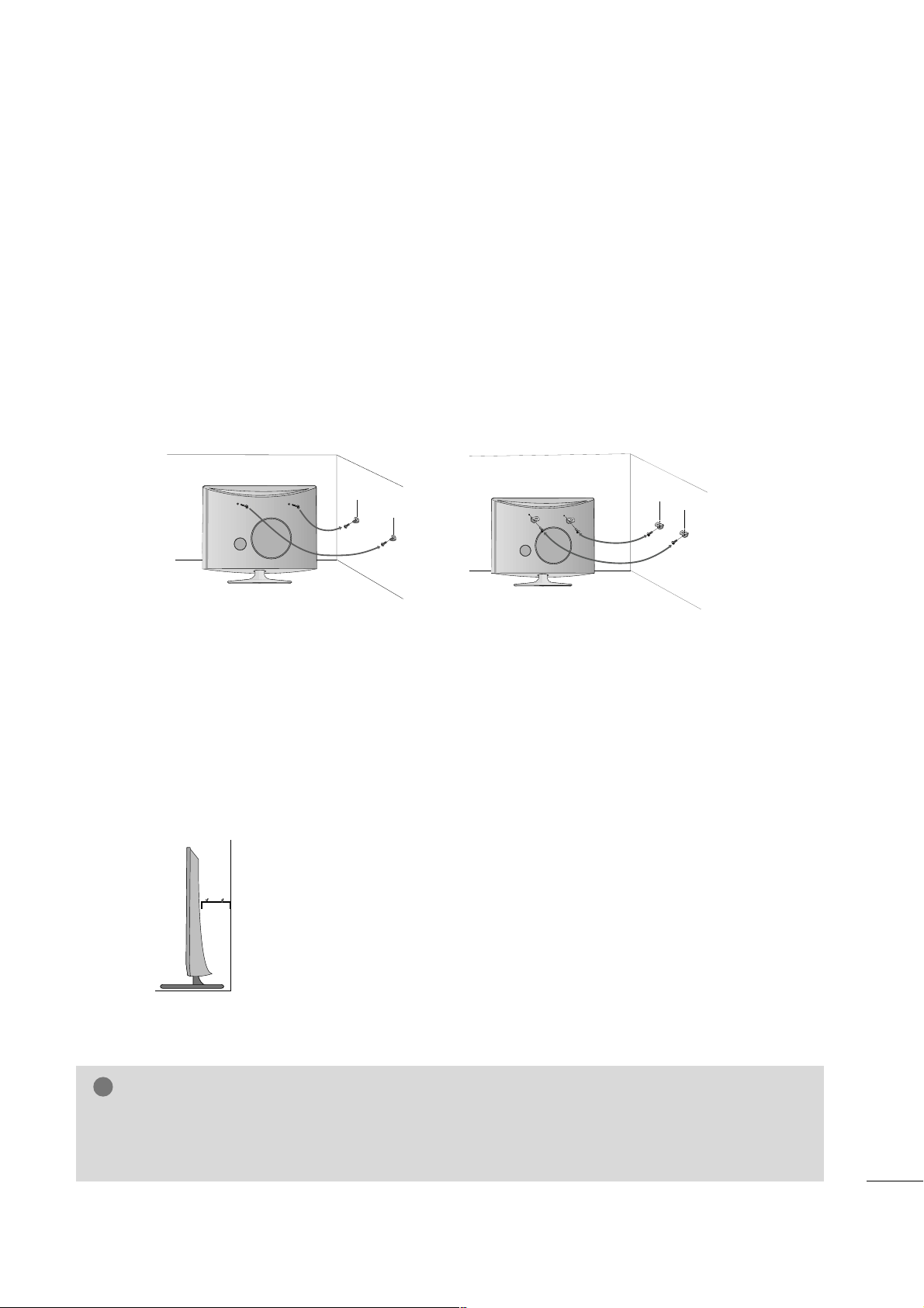
SECURING THE SET TO THE WALL TO PREVENT FALLING WHEN THE SET IS USED ON A STAND
We recommend that you set up the set close to a wall so it cannot fall over if pushed backwards.
Additionally, we recommend that the set be attached to a wall so it cannot be pulled in a forward direction,
potentially causing injury or damaging the product.
Caution: Please make sure that children don’t climb on or hang from the set.
■
Insert the eye-bolts (or set brackets and bolts) to tighten the product to the wall as shown in the picture.
*If your product has the bolts in the eye-bolts position before inserting the eye-bolts, loosen the bolts.
* Insert the eye-bolts or set brackets/bolts and tighten them securely in the upper holes.
Secure the wall brackets with the bolts (sold separately) to the wall. Match the height of the bracket that is
mounted on the wall to the holes in the product.
Ensure the eye-bolts or brackets are tightened securely.
■
Use a sturdy rope or cord (sold separately) to tie the product. It is
safer to tie the rope so it becomes horizontal between the wall and the
product.
■
Image shown may differ from your set.
GG
When moving the set, undo the cords first.
GG
Use a platform or cabinet strong enough and large enough to support the size and weight of the set.
GG
To use the set safely make sure that the height of the bracket on the wall and the one on the set are the same.
NOTE
!
8
PREPARATION
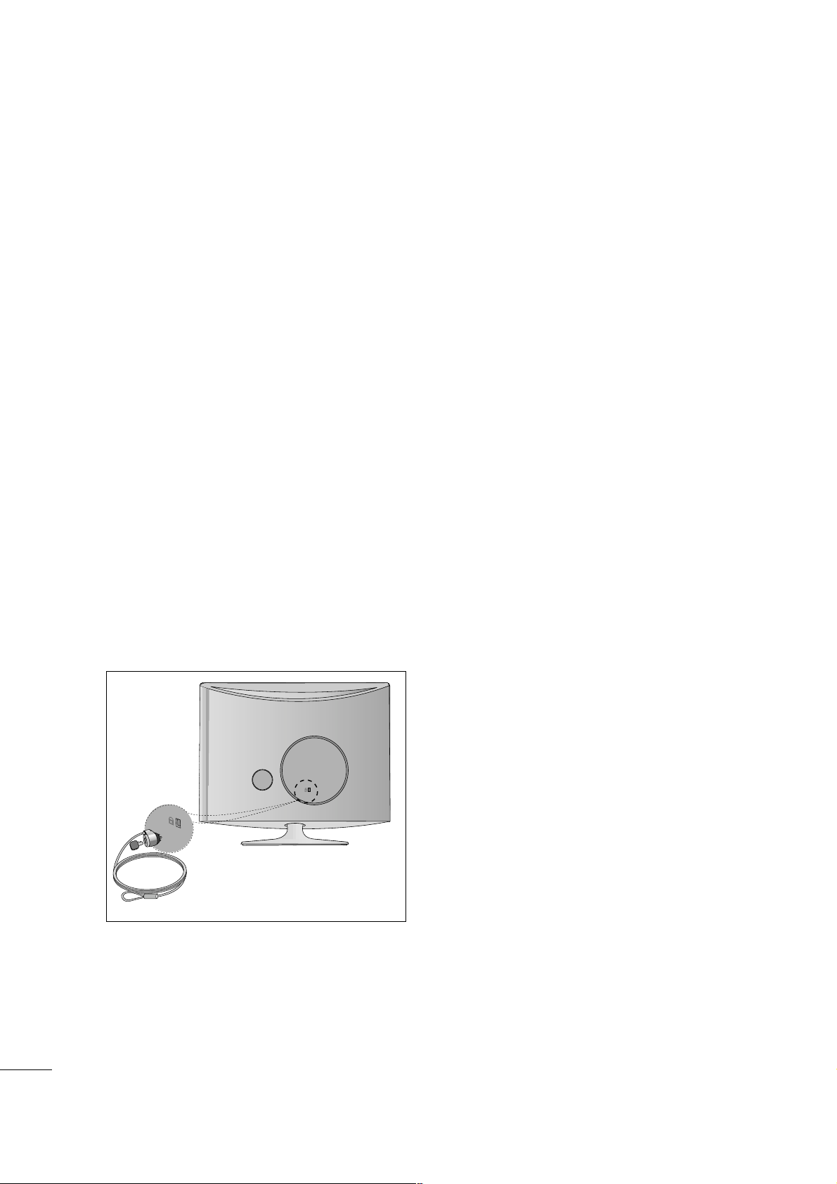
KENSINGTON SECURITY SYSTEM
- The product is equipped with a Kensington Security System connector on the back panel. Connect the
Kensington Security System cable as shown below.
- For detailed installation and use of the Kensington Security System, refer to the user’s guide provided with
the Kensington Security System.
For further information, contact
hhttttpp:://// wwwwww..kkeennss ii nnggttoonn.. ccoomm
, the internet homepage of the
Kensington company. Kensington sells security systems for expensive electronic equipment such as notebook PCs and LCD projectors.
NOTE
- The Kensington Security System is an optional accessory available at most electronics stores.
NOTES
a. If the product feels cold to the touch, there may be a small “flicker” when it is turned on.
This is normal, there is nothing wrong with product.
b. Some minute dot defects may be visible on the screen, appearing as tiny red, green, or blue spots.
However, they have no adverse effect on the monitor's performance.
c. Avoid touching the LCD screen or holding your finger(s) against it for long periods of time.
9
PREPARATION
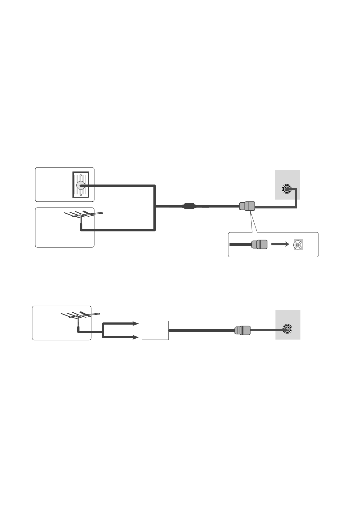
■
For optimum picture quality, adjust antenna direction.
■
An antenna cable and converter are not supplied.
■
To prevent equipment damage, never plug in any power cords until you have finished connecting all equipment.
Multi-family Dwellings/Apartments
(Connect to wall antenna socket)
Single-family Dwellings /Houses
(Connect to wall jack for outdoor antenna)
Outdoor
Antenna
(VHF, UHF)
Wall
Antenna
Socket
RF Coaxial Wire (75 ohm)
ANTENNA CONNECTION
Antenna
UHF
VHF
■
In poor signal areas, to get better picture quality, install a signal amplifier to the antenna as shown above.
■
If signal needs to be split for two TVs, use an antenna signal splitter for connection.
ANTENNA/
CABLE IN
ANTENNA/
CABLE IN
Signal
Amplifier
10
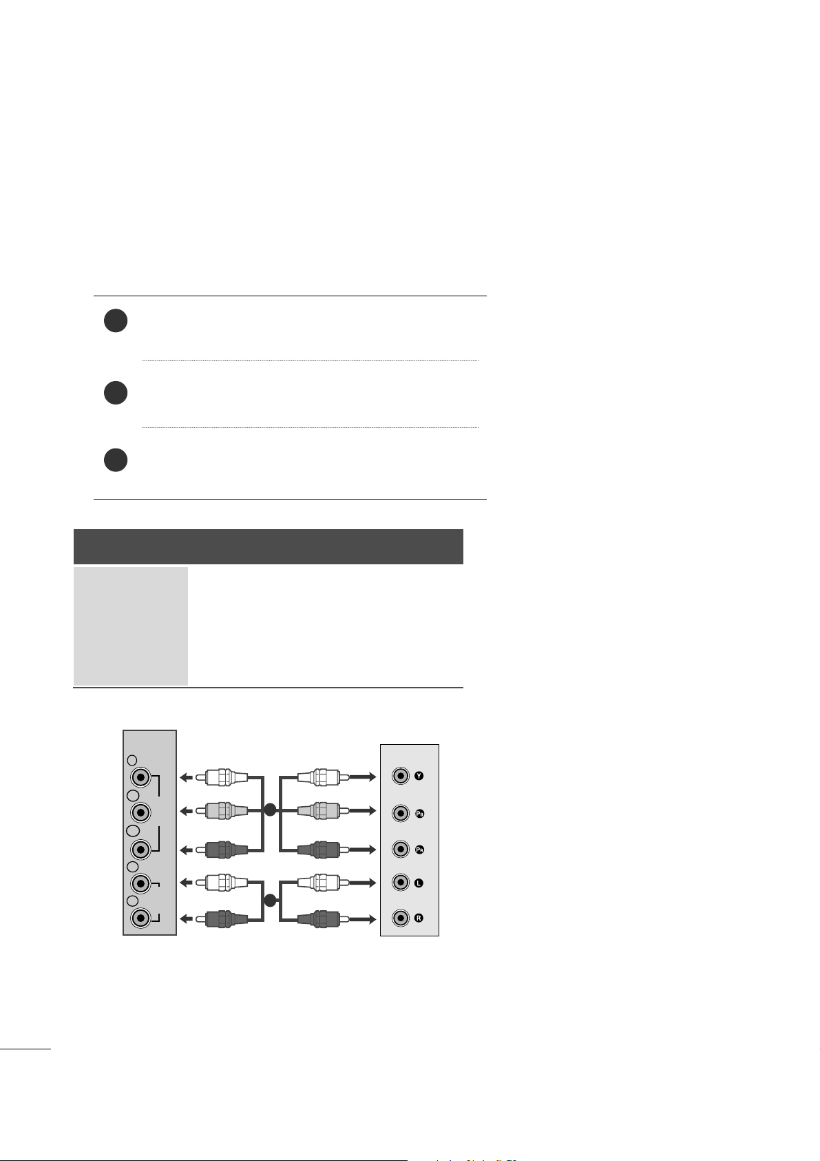
EXTERNAL EQUIPMENT SETUP
Connect the SET-TOP outputs to the
CCOOMMPPOONNEENNTT IINN
VVII DDEEOO
sockets (YP
B PR) on the set.
Connect the audio cable from the SET-TOP to
CCOO MM PPOO--
NNEENN TT II NN AAUUDD II OO
sockets of the set.
Press the
IINNPP UU TT
button to select Component.
2
3
1
HD RECEIVER SETUP
■
To prevent the equipment damage, never plug in any power cords until you have finished connecting all equipment.
■
The image shown may be somewhat different from your set.
When connecting with a component cable
Signal
480i
480p
576p
720p/1080i
1080p
Component
Yes
Yes
No
Yes
Yes
HDMI
No
Yes
Yes
Yes
Yes
VIDEO
COMPONENT
IN
AUDIO
Y
P
B
P
R
L
R
1
2
11
EXTERNAL EQUIPMENT SETUP
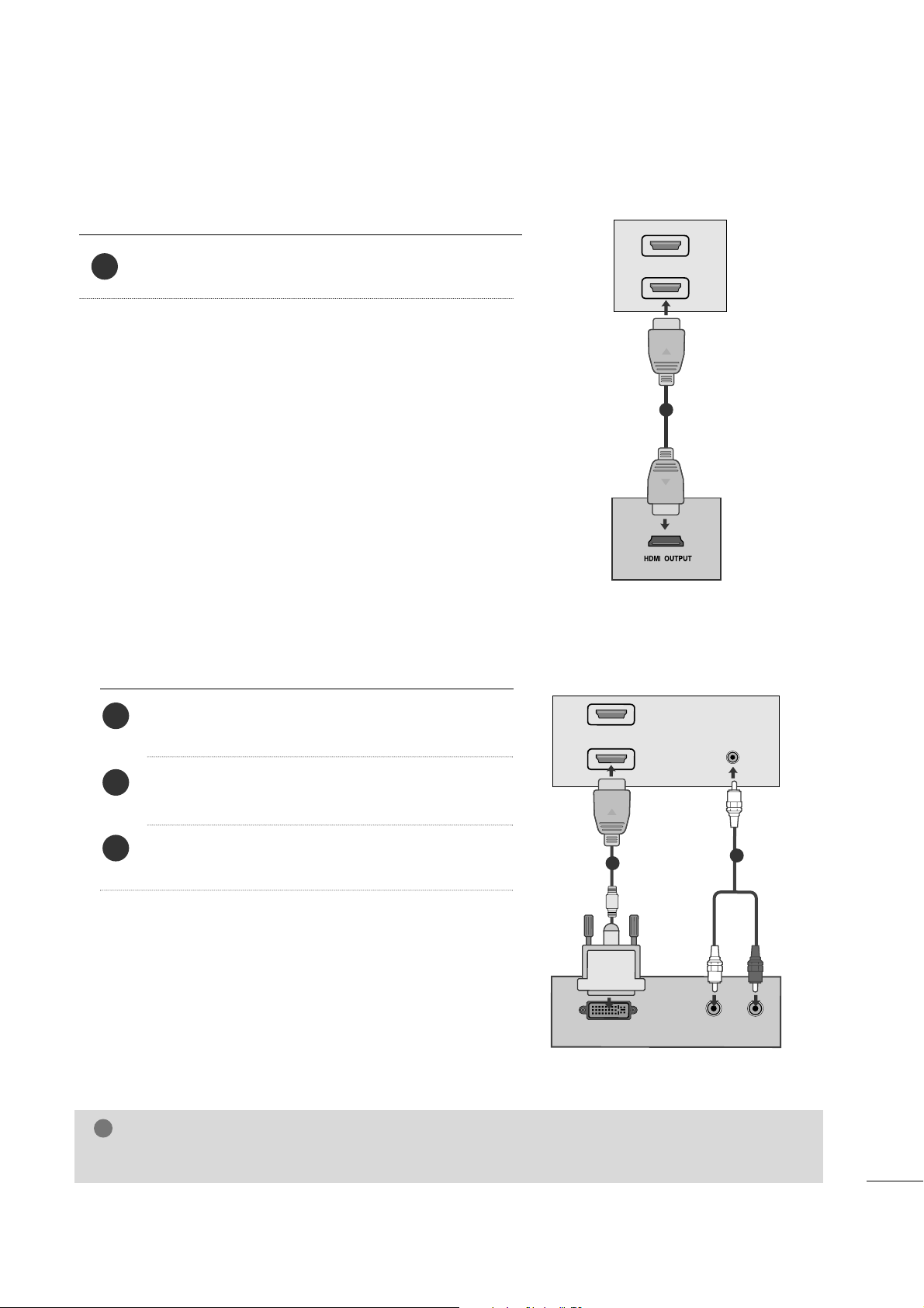
When connecting with a HDMI
Connect the HDMI output of the digital set-top box to the
HH DDMMII IINN
jack on the set.
1
Connect the digital set-top box to
HHDDMMII IINN
jack on
the set.
Connect the audio output of the digital set-top box to
the
AA UUDD IIOO IINN ((RRGGBB// DDVVII ))
jack on the set.
Turn on the digital set-top box. (Refer to the owner’s
manual for the digital set-top box.
)
2
3
1
When connecting with a HDMI to DVI cable
HDMI IN
1
2
1
DVI OUTPUT
AUDIO
R
L
A
U
D
IO
IN
(R
G
B
/D
V
I)
HDMI IN
1
2
1
2
NOTE
!
GG
HDMI Input does not support PC mode. If it is connected PC, the screen may not display properly.
12
EXTERNAL EQUIPMENT SETUP
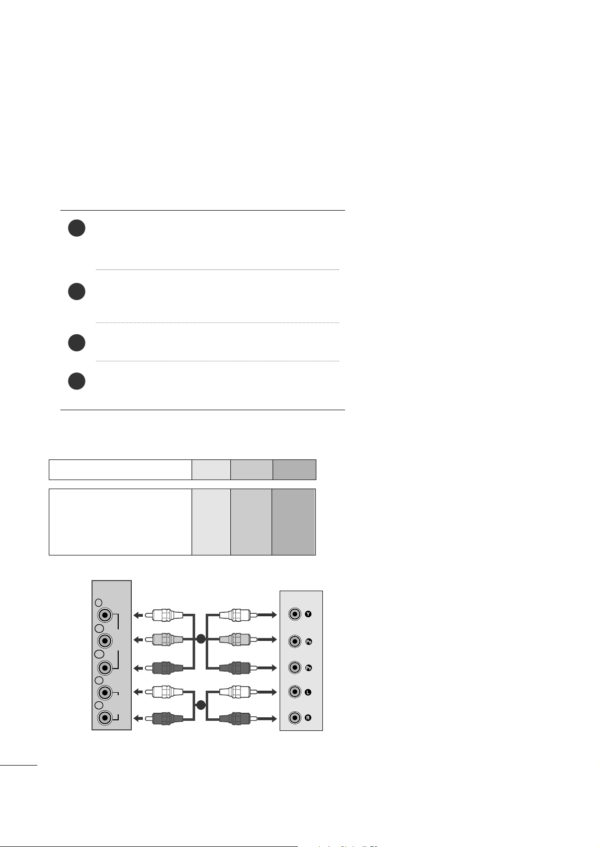
DVD SETUP
When connecting with a component cable
Component Input ports
To get better picture quality, connect a DVD player to the component input ports as shown below.
Component ports on the set
YPBP
R
Video output ports
on DVD player
Y
Y
Y
Y
P
B
B-Y
Cb
Pb
P
R
R-Y
Cr
Pr
Connect the video output sockets (YPBPR) of the DVD to
the
CCOOMMPP OONN EENN TT II NN VVII DDEEOO
sockets (YP
B
PR
) of the
set.
Connect the audio cable from the DVD to
CCOOMMPPOO NNEE NNTT
IINN AAUU DDIIOO
sockets of the set.
Press the
IINNPP UU TT
button to select
Component.
Press the
PPLLAAYY
button on the DVD.
The DVD playback picture appears on the screen.
2
3
4
1
VIDEO
COMPONENT
IN
AUDIO
Y
P
B
P
R
L
R
1
2
13
EXTERNAL EQUIPMENT SETUP
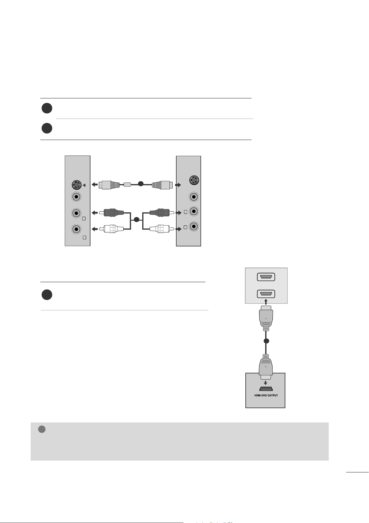
When connecting HDMI cable
Connect the HDMI output of the DVD to the
HHDDMMII IINN
jack on the set.
1
GG
HDMI supports video and audio. You do not need to connect a sperate audio cable.
GG
If the DVD player does not support Auto HDMI, you need to set the DVD output resolution appropriately.
NOTE
!
HDMI IN
1
2
1
When connecting S-Video
Connect the S-Video output of the DVD to the S-Video in put on the set.
Connect the audio output of the DVD to the AUDIO in put on the set.
1
2
VIDEO AUDIO
(MONO)
S-VIDEO
L
R
AV-IN
VIDEO
S-VIDEO
L
R
1
2
14
EXTERNAL EQUIPMENT SETUP
VCR SETUP
■
To avoid picture noise (interference), leave an adequate distance between the VCR and the set.
■
If a user uses 4:3 picture format for a long time, an afterimage may remain on the sides of the screen for a
short time.
OUTPUT
SWITCH
ANT IN
R
S-VIDEO VIDEO
ANT OUT
L
ANTENNA/
CABLE IN
Wall Jack
Antenna
1
2
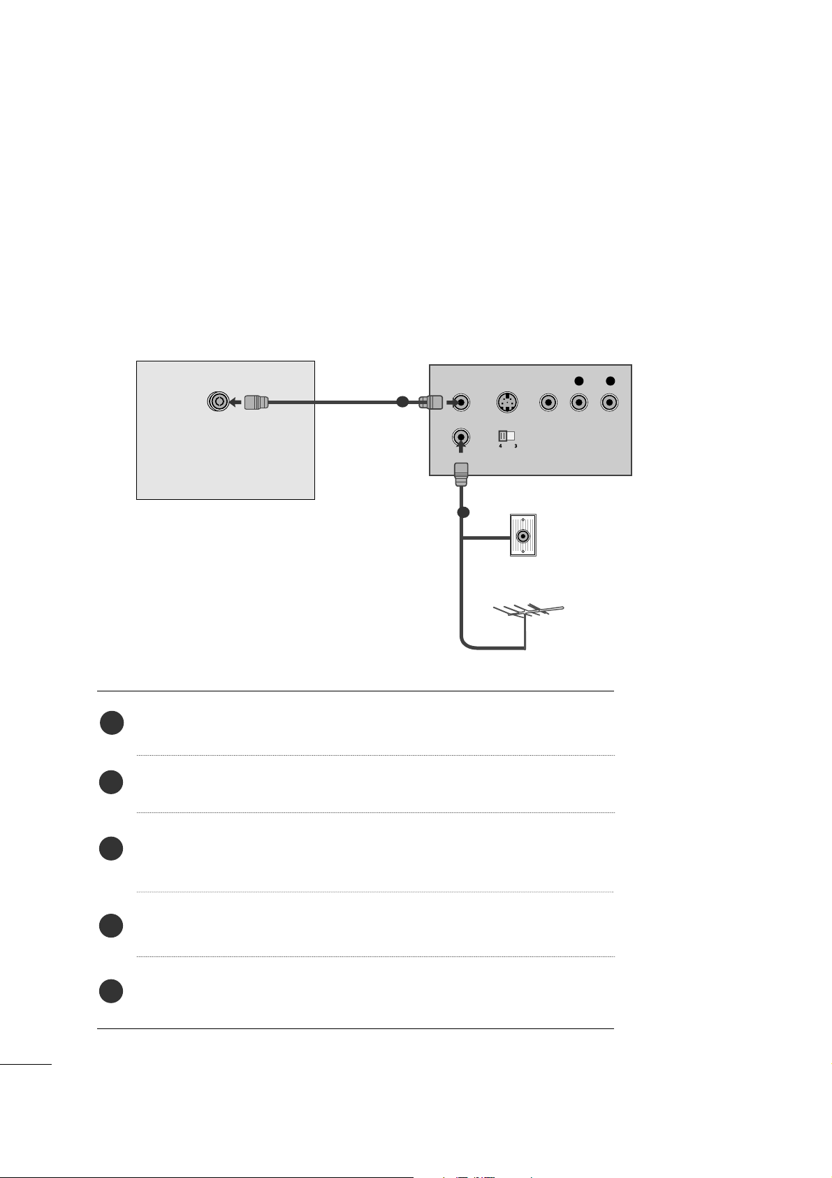
When connecting with an antenna
Connect the RF out socket of the VCR to the antenna socket of the set.
Connect the antenna cable to the RF aerial in socket of the VCR.
Store the VCR channel on a desired channel number using the ‘Manual
channel tuning’ section.
Select the Channel number where the VCR channel is stored.
Press the
PPLLAAYY
button on the VCR.
1
2
3
4
5
15
EXTERNAL EQUIPMENT SETUP
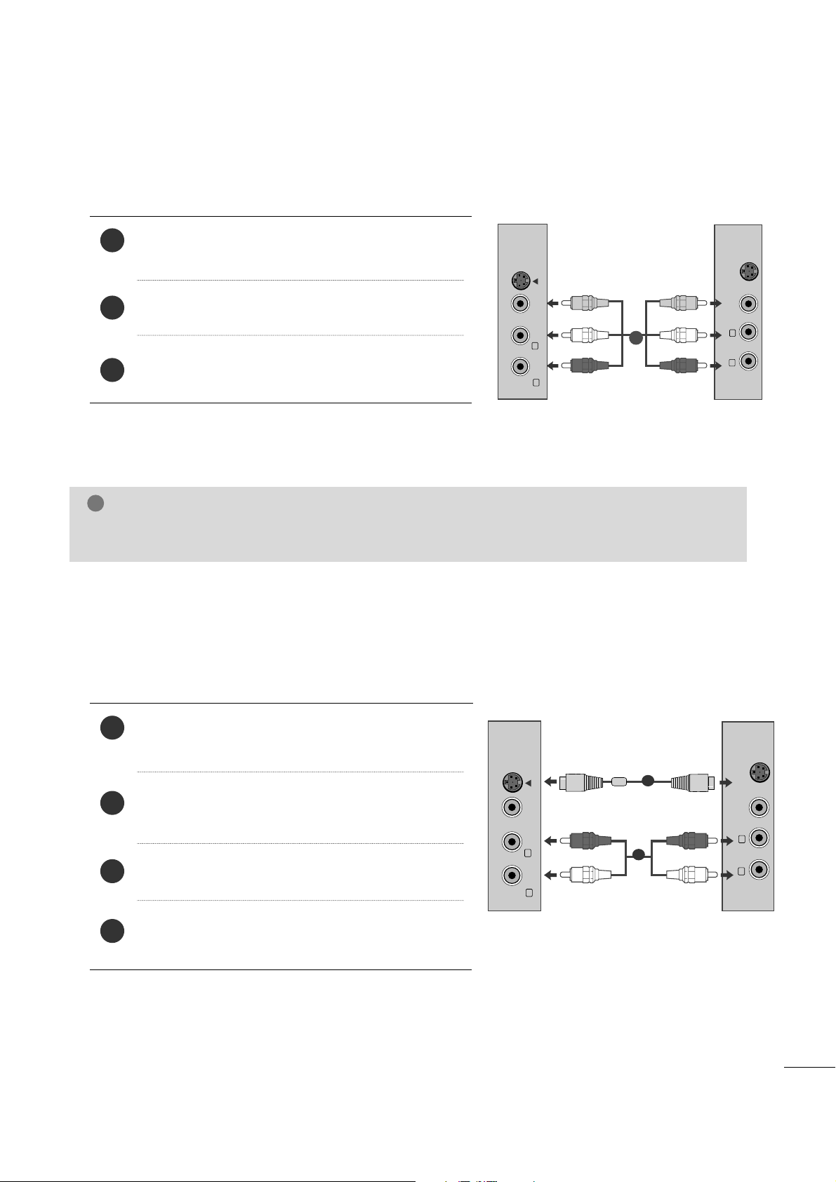
When connecting with a RCA cable
Connect the audio/video out sockets of the VCR to
AUDIO/VIDEO in sockets of the set.
Press the INPUT button to select AV.
Press the PLAY button on the VCR.
The VCR playback picture appears on the screen.
2
3
1
When connecting with an S-Video cable
Connect the S-Video socket of the VCR to the SVIDEO socket of the set.
Connect the audio cable from the S-VIDEO of the VCR
to the AUDIO sockets of the set.
Press the INPUT button to select AV.
Press the PLAY button on the VCR.
The VCR playback picture appears on the screen.
2
3
4
1
NOTE
!
GG
If you have a mono VCR, connect the audio cable from the VCR to the AUDIO L/MONO jack of the set.
VIDEO AUDIO
(MONO)
S-VIDEO
L
R
AV-IN
VIDEO
S-VIDEO
L
R
VIDEO AUDIO
(MONO)
S-VIDEO
L
R
AV-IN
VIDEO
S-VIDEO
L
R
1
2
1
16
EXTERNAL EQUIPMENT SETUP
PC SETUP
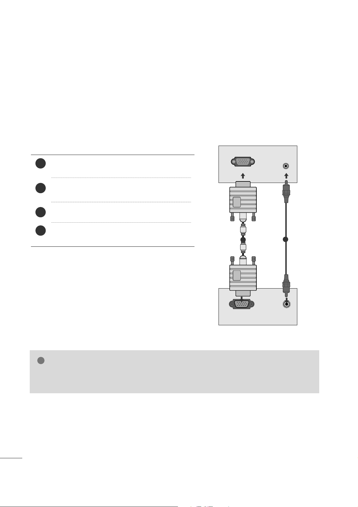
This product provides Plug and Play capability, meaning that the PC adjusts automatically to the set's settings.
When connecting with a D-sub 15 pin cable
4
Connect the signal cable from the monitor output socket of
the PERSONAL COMPUTER to the PC input socket of the set.
Connect the audio cable from the PC to the
AA UUDDIIOO II NN
((RRGG BB// DDVVII))
sockets of the set.
Press the INPUT button to select RGB.
Switch on the PC, and the PC screen appears on the set.
The set can be operated as a PC monitor.
2
3
1
RGB OUTPUT
AUDIO
AUDIO IN
(RGB/DVI)
RGB IN (PC)
1
2
NOTE
!
GG
User must use shielded signal interface cables (D sub 15 pin cable, DVI cable) with ferrite cores to maintain standard compliance for the product.
17
EXTERNAL EQUIPMENT SETUP
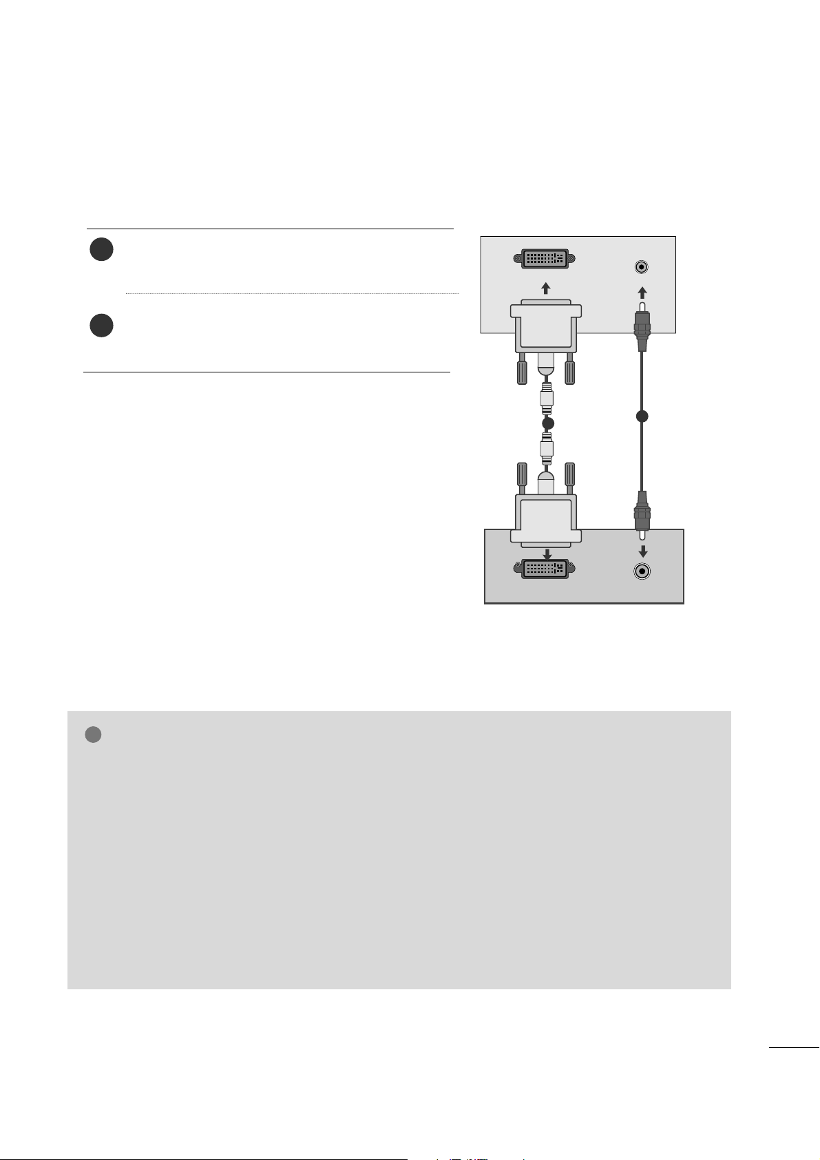
When connecting with a DVI cable
Connect the DVI output of the PC to the
DDVVII-- DD IINN
jack on the set.
Connect the audio cable from the PC to the
AA UU DDIIOO
IINN (( RRGGBB//DDVVII))
sockets of the set.
2
1
NOTE
!
GG
If the set is cold, there may be a small “flicker” when
the set is switched on. This is normal, there is nothing wrong with the set.
GG
If possible, use the 1920x1080@60Hz video mode
to obtain the best image quality for your LCD monitor. If used with other resolutions, some scaled or
processed pictures may appear on the screen. The
set has been preadjusted to the mode
1920x1080@60Hz.
GG
Some dot defects may appear on the screen, like
Red, Green or Blue spots. However, this will have no
impact or effect on the monitor performance.
GG
Do not press the LCD screen with your finger for a
long time as this may produce some temporary distortion effects on the screen.
GG
Avoid keeping a fixed image on the set’s screen for
prolonged periods of time. The fixed image may
become permanently imprinted on the screen; use a
screen saver when possible.
AUDIO
DVI OUTPUT
AUDIO IN
(RGB/DVI)
DVI-D IN (PC)
1
2
18
EXTERNAL EQUIPMENT SETUP
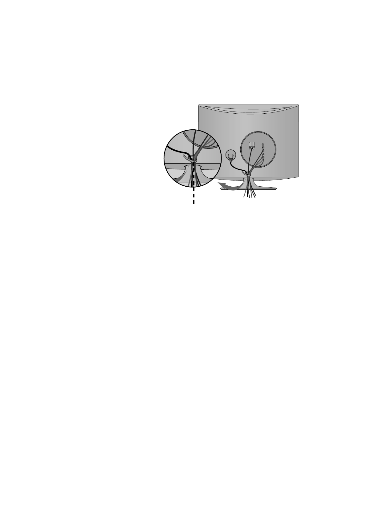
Tie cables together with a cable tie as shown in the
illustration.
Cable tie
BACK COVER FOR WIRE ARRANGEMENT
19
EXTERNAL EQUIPMENT SETUP
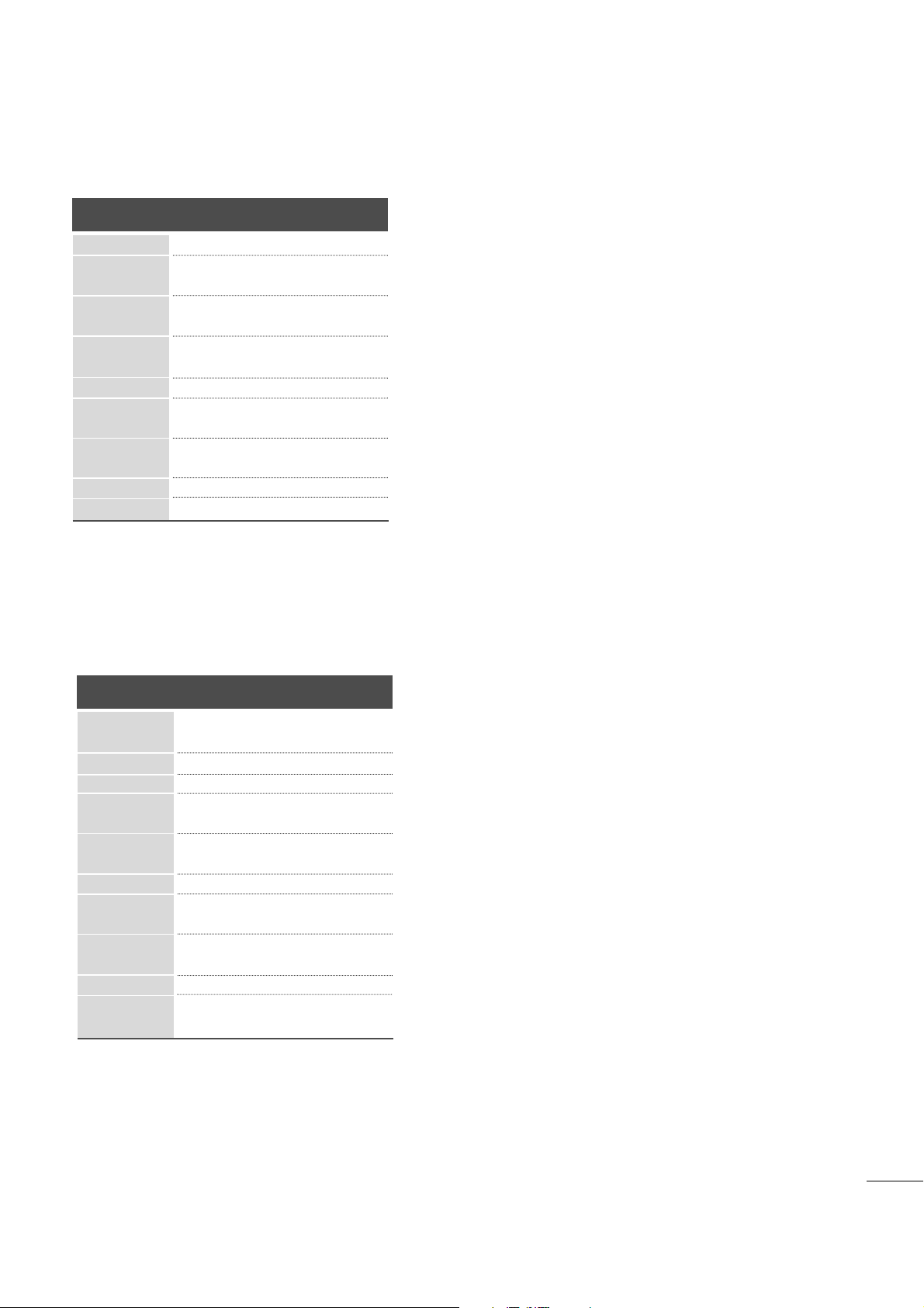
RGB/DVI[PC]
HDMI[DTV] supported mode
60
60
50
50
60
60
60
60
50
24
24
30
30
50
60
60
31.47
31.5
31.25
37. 5
44.96
45
33.72
33.75
28.125
26.97
23
33.716
33.75
56.25
67. 43
67. 5
Resolution
720x480/60p
720x576/50p
1280x720/60p
1280x720/50p
Horizontal
Frequency(kHz)
Vertical
Frequency(Hz)
1920x1080/60i
1920x1080/50i
1920x1080/24p
1920x1080/30p
1920x1080/50p
1920x1080/60p
Resolution
640x480
800x600
720x40 0
10 2 4 x 7 6 8
Horizontal
Frequency(kHz)
Vertical
Frequency(Hz)
70
60
75
60
75
60
75
75
60
75
60
60
60
60
31.468
31.469
37. 500
37. 879
46.875
48.363
60.123
67. 500
63.981
79.976
64.674
65.290
75.000
66.587
12 8 0 x 1 0 2 4
115 2 x 86 4
1680x1050
1920x1080
1600x1200
20
EXTERNAL EQUIPMENT SETUP
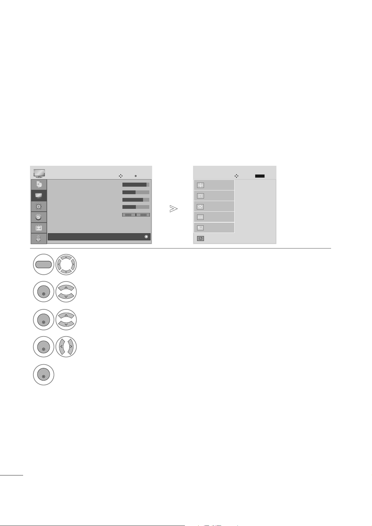
SCREEN SETUP FOR PC MODE
Returns Position, Size and Phase to the default factory settings.
This function works in the following mode: RGB[PC].
Screen Reset
1
MENU
Select PICTURE.
2
Select SCREEN(RGB-PC).
3
ENTER
Select Reset.
5
ENTER
Run Reset.
• Contrast : 90
• Brightness : 50
• Sharpness : 70
• Colour : 50
• Tint : 0
• Advanced Control
• Reset
PICTURE
Move
Enter
D
Screen(RGB-PC)
Initialize Settings.
Auto Config.
SCREEN
Move
Prev.
BACK
Resolution
Position
Size
Phase
Reset
G
ENTER
4
ENTER
Select Ye s .
• Press the MENU button to close the menu window.
• Press the RETURN button to move to the previous menu screen.
RG
21
EXTERNAL EQUIPMENT SETUP
If the picture is not clear after auto adjustment and especially if characters are still shaky, adjust the picture phase manually.
This function works in the following mode: RGB[PC].
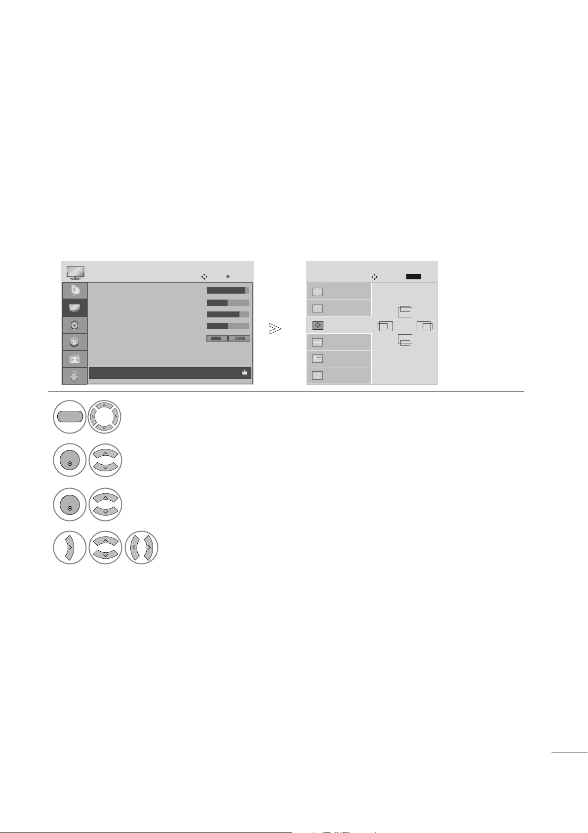
Adjustment for screen Position, Size, Phase
1
Select PICTURE.
2
Select SCREEN(RGB-PC).
3
Select Position, Size or Phase.
4
Make appropriate adjustments.
Auto Config.
SCREEN
Move
Resolution
Position
G
Size
Phase
Reset
GF
D
E
• Press the MENU button to close the menu window.
• Press the RETURN button to move to the previous menu screen.
Prev.
BACK
• Contrast : 90
• Brightness : 50
• Sharpness : 70
• Colour : 50
• Tint : 0
• Advanced Control
• Reset
PICTURE
Move
Enter
D
Screen(RGB-PC)
RG
MENU
ENTER
ENTER
22
EXTERNAL EQUIPMENT SETUP
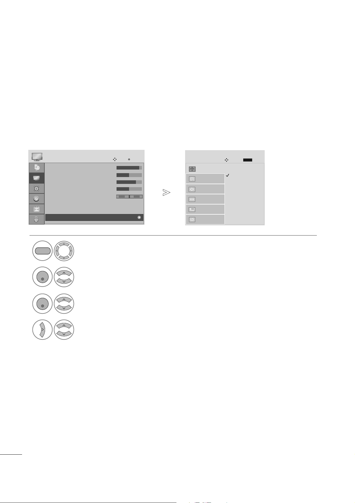
To view a normal picture, set the resolution to match what the PC is using.
This function works in the following resolution in RGB[PC] mode.
Selecting Resolution
1
Select PICTURE.
2
Select SCREEN(RGB-PC).
3
Select Resolution.
4
Select the desired resolution.
MENU
ENTER
ENTER
• Press the MENU button to close the menu window.
•
Press the RETURN button to move to the previous menu screen.
1400 x 1050
1680 x 1050
Auto Config.
SCREEN
Move
Resolution
G
Position
Size
Phase
Reset
Prev.
BACK
• Contrast : 90
• Brightness : 50
• Sharpness : 70
• Colour : 50
• Tint : 0
• Advanced Control
• Reset
PICTURE
Move
Enter
D
Screen(RGB-PC)
RG
23
EXTERNAL EQUIPMENT SETUP
1
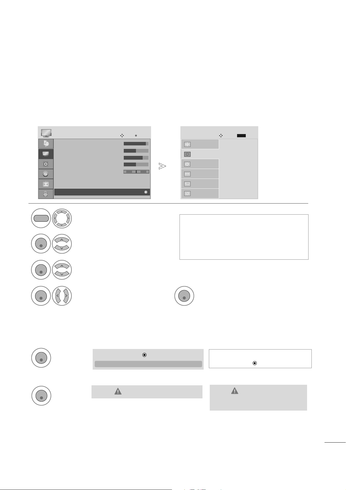
Automatically adjusts picture position and minimizes image instability. After adjustment, if the image is still
not correct, your set is functioning properly but needs further adjustment.
AAuu ttoo ccoonnff iigg uurr ee
This function is for automatic adjustment of the screen position, clock, and phase The displayed image will
be unstable for a few seconds while the auto configuration is in progress.
Auto Configure (RGB [PC] mode only)
• If the position of the image is still not correct,
try Auto adjustment again.
•
If picture needs to be adjusted again after Auto
adjustment in RGB (PC), you can adjust the
PPoo ss iittiioonn, SSii zzee
or
PPhhaa ss ee
.
Select PICTURE.
11.. UU ssiinngg OO SSDD
2
Select SCREEN(RGB-PC).
3
Select Auto Config.
To S e t
Auto Config.
G
SCREEN
Move
Resolution
Position
Size
Phase
Reset
MENU
ENTER
ENTER
Prev.
BACK
Run Auto Config.
ENTER
4
5
Select Ye s .
ENTER
• Contrast : 90
• Brightness : 50
• Sharpness : 70
• Colour : 50
• Tint : 0
• Advanced Control
• Reset
PICTURE
Move
Enter
D
Screen(RGB-PC)
RG
• Press the MENU button to close the menu window.
• Press the RETURN button to move to the previous menu screen.
•
If you don’t want Auto Configure, do
not press OK
22.. UU ss iinn gg OOKK ((RReemmoocc oo nn oo rr cc oo nnttrrooll kkeeyy))
1
Press ENTER.
ENTER
TT hh iiss ffuunncc ttiioonn iiss aavvaaiillaabb llee ffoorr RRGG BB ss iiggnn aallss oonnllyy..
AA uuttoo ii nn PPrrooggrreessss
<<11992200 xx 11 008800 RRee ssoolluutt iioonn>>
<<OOtt hheerrss RReess oo lluu ttii oo nn>>
2
Press ENTER.
ENTER
Auto in Progress
For optimal display
change resolution to 1920 x 1080
Auto Config.
GG
OK( )
24
WATCHING TV /PROGRAMME CONTROL
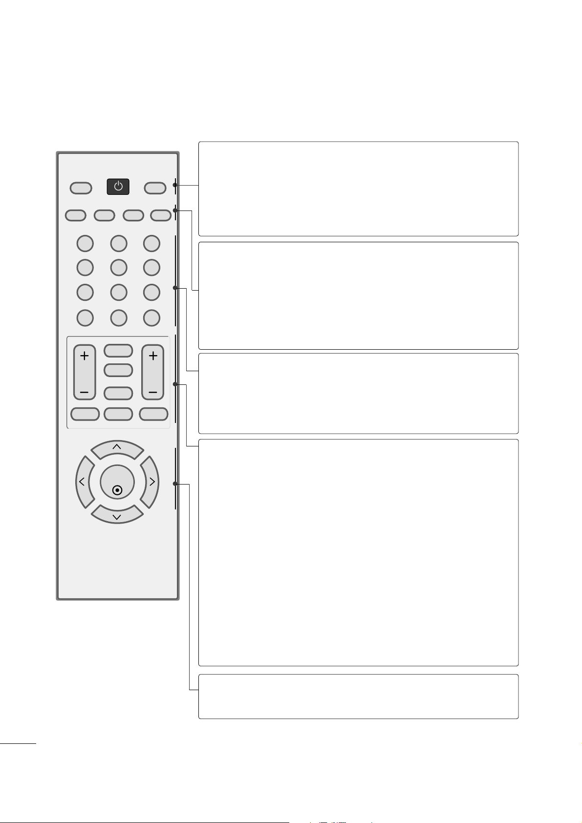
REMOTE CONTROL KEY FUNCTIONS
When using the remote control, aim it at the remote control sensor on the set.
123
456
780-9
VOL CH
ENTER
POWER
MUTE
Q.MENU
MENU
FLASHBK
RETURN
CC
FAV
PICTURE SOUND SAP
RATIO
TV/PC
INPUT
POWER
TV/PC
INPUT
Turns your set on or off.
Selects TV or PC mode.
Switches the set on.
External input modes rotate in regular sequence
PICTURE
SOUND
SAP
RATIO
Toggles through the factory preset picture settings depending on
the viewing environment.
Toggles through preset sound settings.
* Toggles through Mono, Stereo, or SAP when using analog audio.
* DTV mode: Changes the audio language.
Change the spect ratio.
NUMBER button
_(DASH)
FLASHBK
Used to enter a program number for multiple program
channels such s 2-1,2-2,etc.
Tunes to the last channel viewed.
VOLUME UP
/DOWN
FAV
CC
MUTE
CHANNEL
UP/DOWN
Q.MENU
MENU
RETURN
Increase/decrease the sound level.
Scroll through the programmed Favorite channels.
Select a closed caption.
Switch the sound on or off.
Select available channels.
Select the desired quick menu source.
Displays the main menu.
Allows the user to move return one step in an interactive
application or other user interaction function.
THUMBSTICK
(Up/Down/Left
Right/ENTER)
Navigate the on-screen menus and adjust the system settings to your preference.
25
TURNING ON THE TV
WATCHING TV /PROGRAMME CONTROL
First, connect the power cord correctly.
Turn on the power by pressing the power button on the product.
Press the TV/PC button on the remote control.
Set the channel by using the CH + / - buttons or number buttons on the remote control.
2
1
123
456
780-9
VOL CH
ENTER
POWER
MUTE
Q.MENU
MENU
FLASHBK
RETURN
CC
FAV
PICTURE SOUND SAP
RATIO
TV/PC
INPUT
Setup Menu
Note:
a. It will automatically disappear after approx. 40 seconds
unless a button is pressed.
b. Press the
RR EE TTUU RR NN
button to change current OSD into
regular OSD.
If the OSD (On Screen Display) is displayed on the screen
as figure after turning on the set, you can adjust the
Language, Country, Time Zone, Auto channel tuning.
4
3
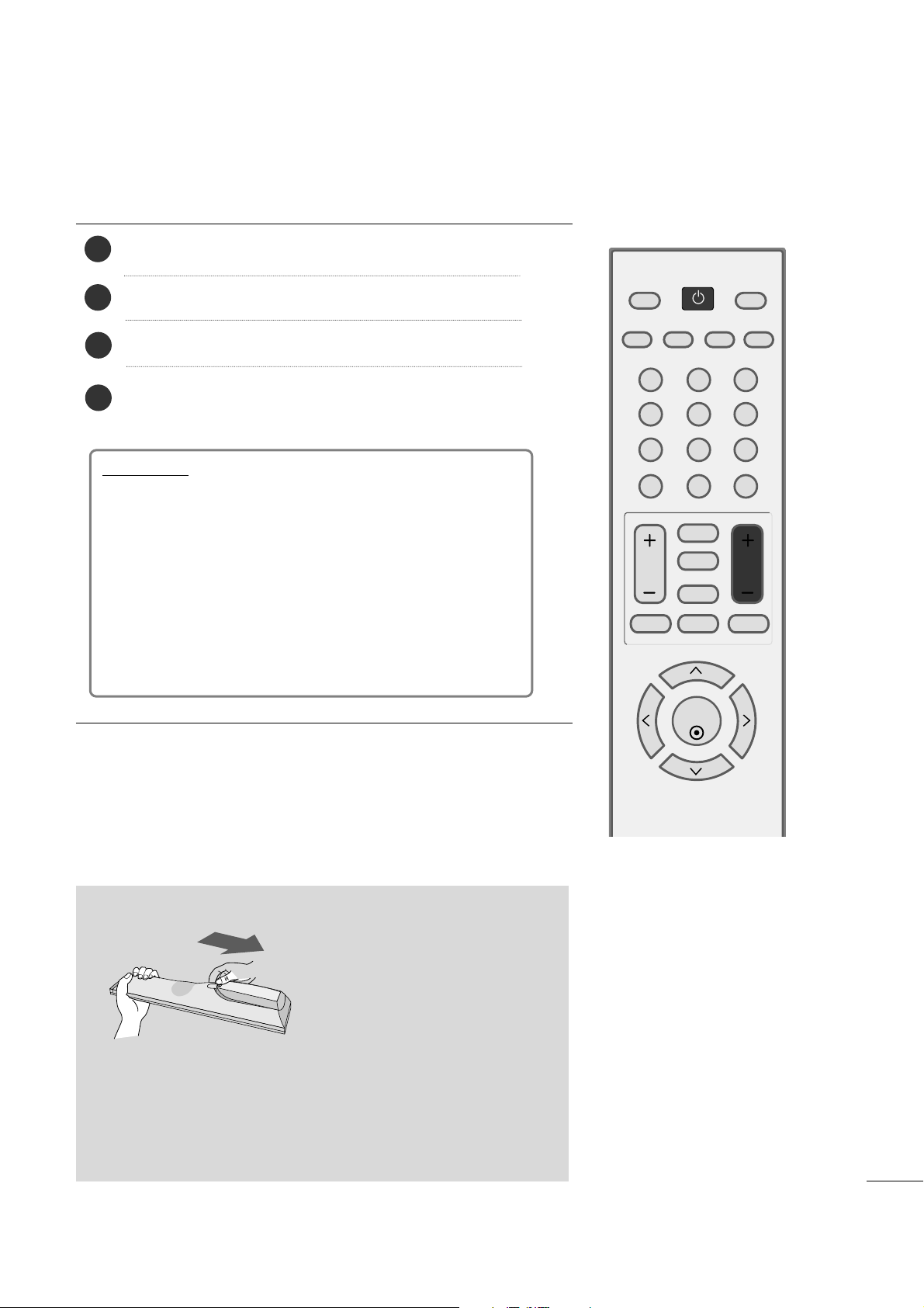
Installing Batteries
■
Open the battery compartment cover on the back and install the
batteries matching correct polarity (+ with +, - with -).
■
Install two 1.5V AAA batteries. Don’t mix old or used batteries with
new ones.
■
Close the cover.
26
WATCHING TV /PROGRAMME CONTROL
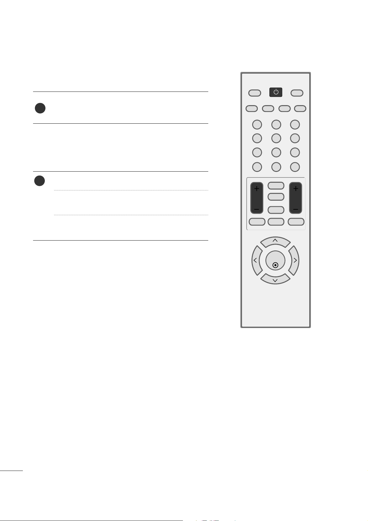
CHANNEL SELECTION
Press the
CCHH ++ or--
or NUMBER buttons to select a
programme number.
1
VOLUME ADJUSTMENT
Press the VOL
++ or--
button to adjust the volume.
If you want to switch the sound off, press the MUTE
button.
You can cancel this function by pressing the MUTE,
VOL
++ or--
.
123
456
780-9
VOL CH
ENTER
POWER
MUTE
Q.MENU
MENU
FLASHBK
RETURN
CC
FAV
PICTURE SOUND SAP
RATIO
TV/PC
INPUT
1
 Loading...