

LG M2362D-PT Owner’s Manual

ENGLISH
OWNER’S MANUAL
MONITOR TV
Please read this manual carefully before operating
your set and retain it for future reference.
MONITOR TV MODELS
M2362D
www.lg.com
1
PREPARATION
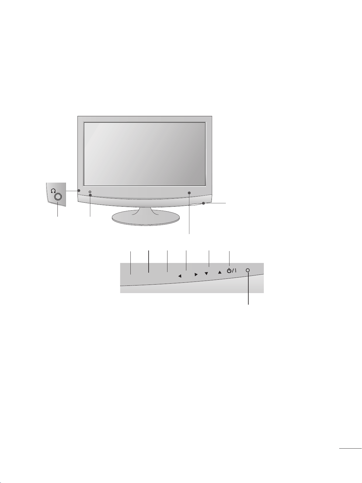
FRONT PANEL CONTROLS
■
This is a simplified representation of the front panel. The image shown may be somewhat different from your set.
INPUT
Button
INPUT
MENU
PR
VOL
OK
MENU
Button
OK
Button
VOLUME
Buttons
PROGRAMME
Buttons
Powe r
Button
Headphone
Jack
IR receiver
(Remote controller
receiver)
LLiigghhtt SSeennss oorr
This is lens for light sensor
select outside luminance,
when setting AUTO
BRIGHT ON.
PPoowweerr IInnddiiccaattoorr
illuminates blue when the
set is switched on.
Note:You can adjust
Power indicator in the
OPTION menu.
22
PREPARATION
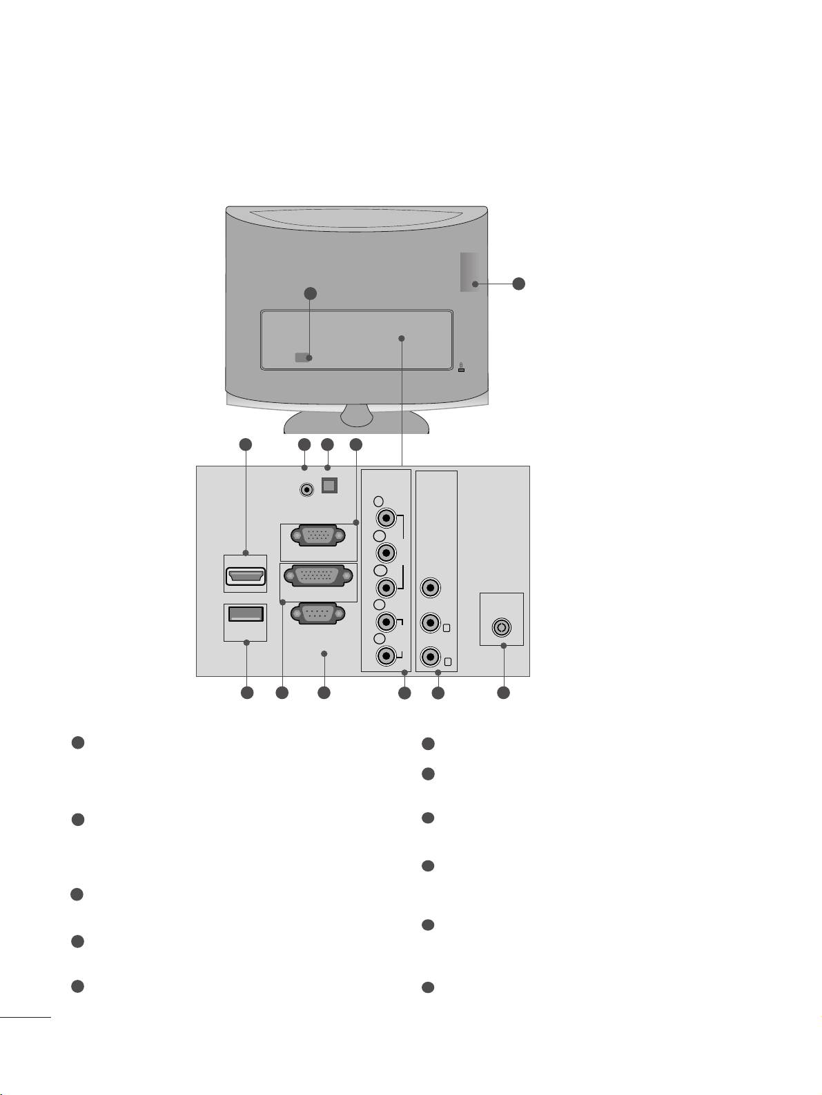
BACK PANEL INFORMATION
PPoowwee rr CCoorrdd SSoocc kk eett
This set operates on AC power. The voltage is indicated
on the Specifications page. Never attempt to operate
the set on DC power.
HHDDMMII IInn pp uutt ((NNoott SSuu pp pp oo rrtt PPCC))
Connect a HDMI signal to HDMI IN.
Or DVI (VIDEO) signal to HDMI IN with DVI to HDMI
cable.
RR GG BB//DD VVII AAuuddiioo II nnppuutt
Connect the audio from a PC.
OOppttiiccaall DDii ggiittaa ll AA uuddii oo OO uutt
Connect digital audio from various types of eguipment
RR GG BB II NN PP UUTT ((PP CC))
Connect the output from a PC.
UUSSBB II NN
DDVV II-- DD IInnppuu tt
Connect the output from a PC.
RR SS -- 22 3322 CC IINN ((CC OONN TTRR OOLL && SSEERRVVIICCEE)) PPOORRTT
Connect to the RS-232C port on a PC.
CCoommppoonneenntt IInnppuutt
Connect a component video/audio device to these
jacks.
AAuu dd ii oo//VViiddeeoo II nnppuutt
Connect audio/video output from an external device to
these jacks.
AAnn tt eenn nnaa IInnppuu tt
Connect over-the-air signals to this jack.
1
2
3
4
5
6
7
8
9
10
11
■
This is a simplified representation of the back panel. The image shown may be somewhat different from your set.
2
8
9 10
1
2
76 11
53 4
HDMI IN 1
USB IN
AUDIO IN
(RGB/DVI)
OPTICAL
AUDIO OUT
RGB IN (PC)
DVI-D IN (PC)
RS-232C IN
(CONTROL & SERVICE)
DIGITAL
COMPONENTINAV IN
Y
P
B
VIDEO
P
R
L
AUDIO
R
VIDEO -AUDIO-
(MONO)
L
R
ANTENNA/
CABLE IN
33
PREPARATION
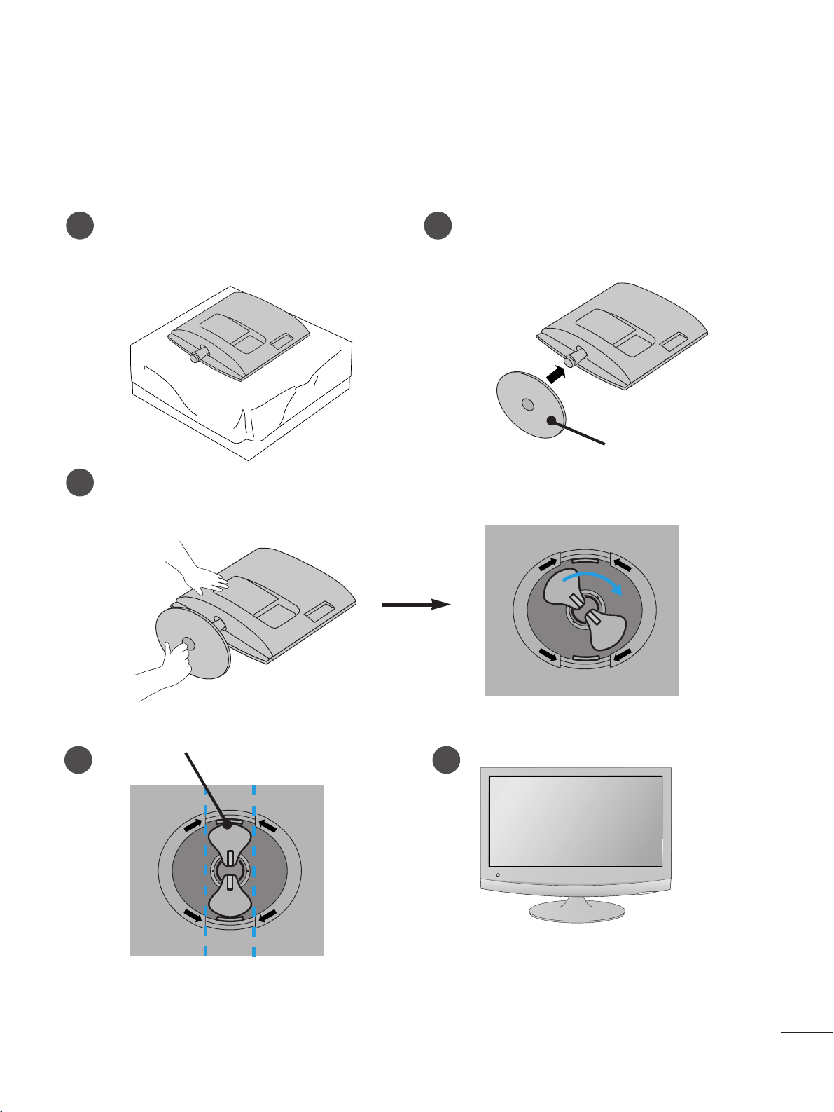
STAND INSTALLATION
■
The image shown may be somewhat different from your set.
1
2
3
Carefully place the product screen side down on a
cushioned surface that will protect product and
screen from damage.
Insert the
SSttaann dd BBaassee
into the product
Turn the
SSttaann dd BBaass ee LLoocckk
through 90
° to fix the stand base to the stand body.
SSttaann dd BBaass ee LLoocckk
<<LLoocc kk eedd>>
4 5
O
P
E
N
O
P
E
N
O
P
E
N
O
P
E
N
SSttaann dd BBaassee
44
PREPARATION
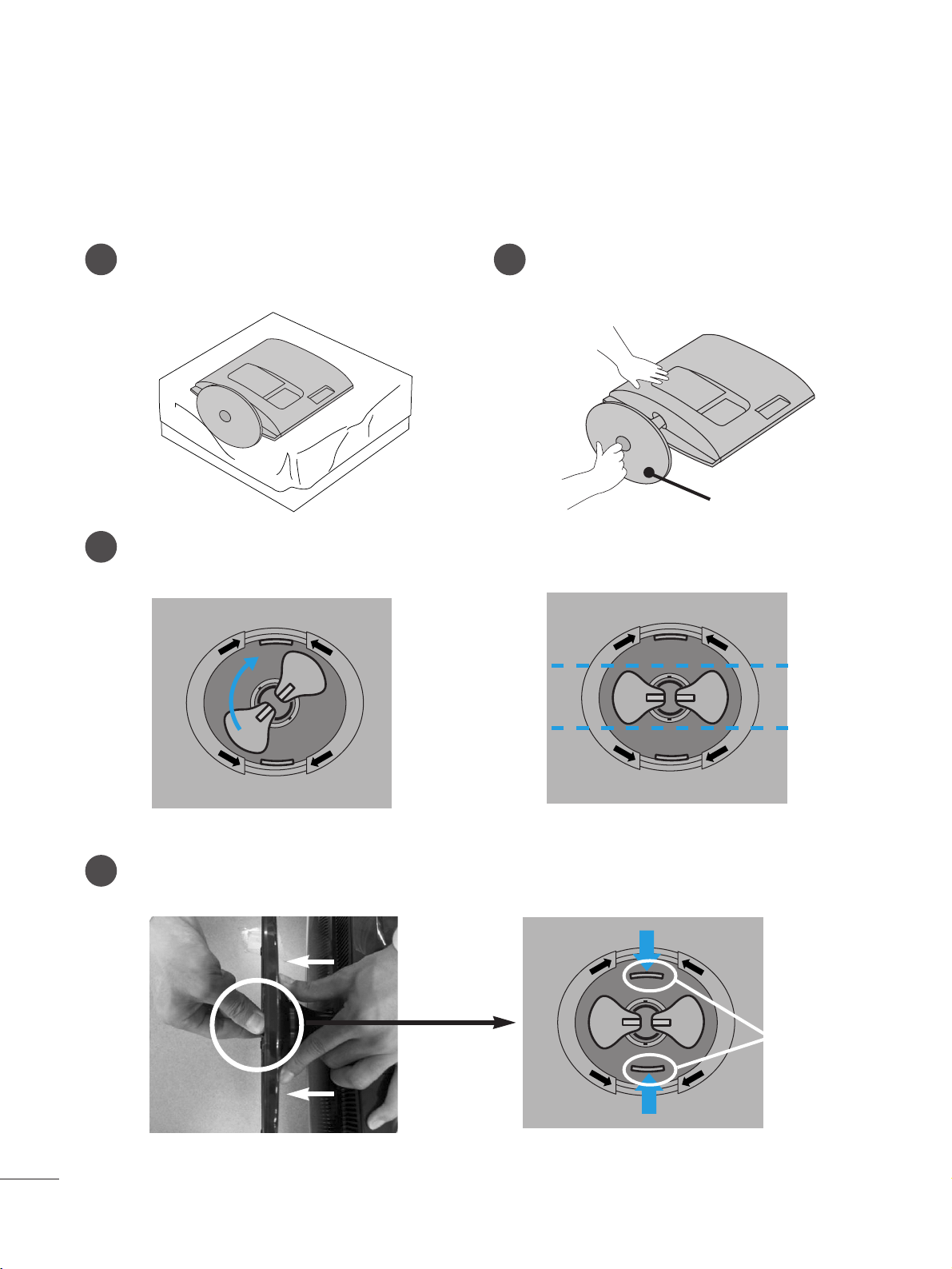
DETACHING STAND
■
The image shown may be somewhat different from your set.
1
2
3
4
Place the set screen side down on a cushion or
soft cloth.
Detach the monitor to the
SSttaann dd BBaass ee
by
turning the screw to the left.
Turn the
SSttaann dd BBaass ee LLoocckk
through 90
° to separate the Stand Base from the Stand Body.
Pushing
LLaatt cc hh
inside, Take the stand base from stand body.
O
P
E
N
O
P
E
N
O
P
E
N
O
P
E
N
O
P
E
N
O
P
E
N
LLaatt cc hh
SSttaann dd BBaassee
55
PREPARATION
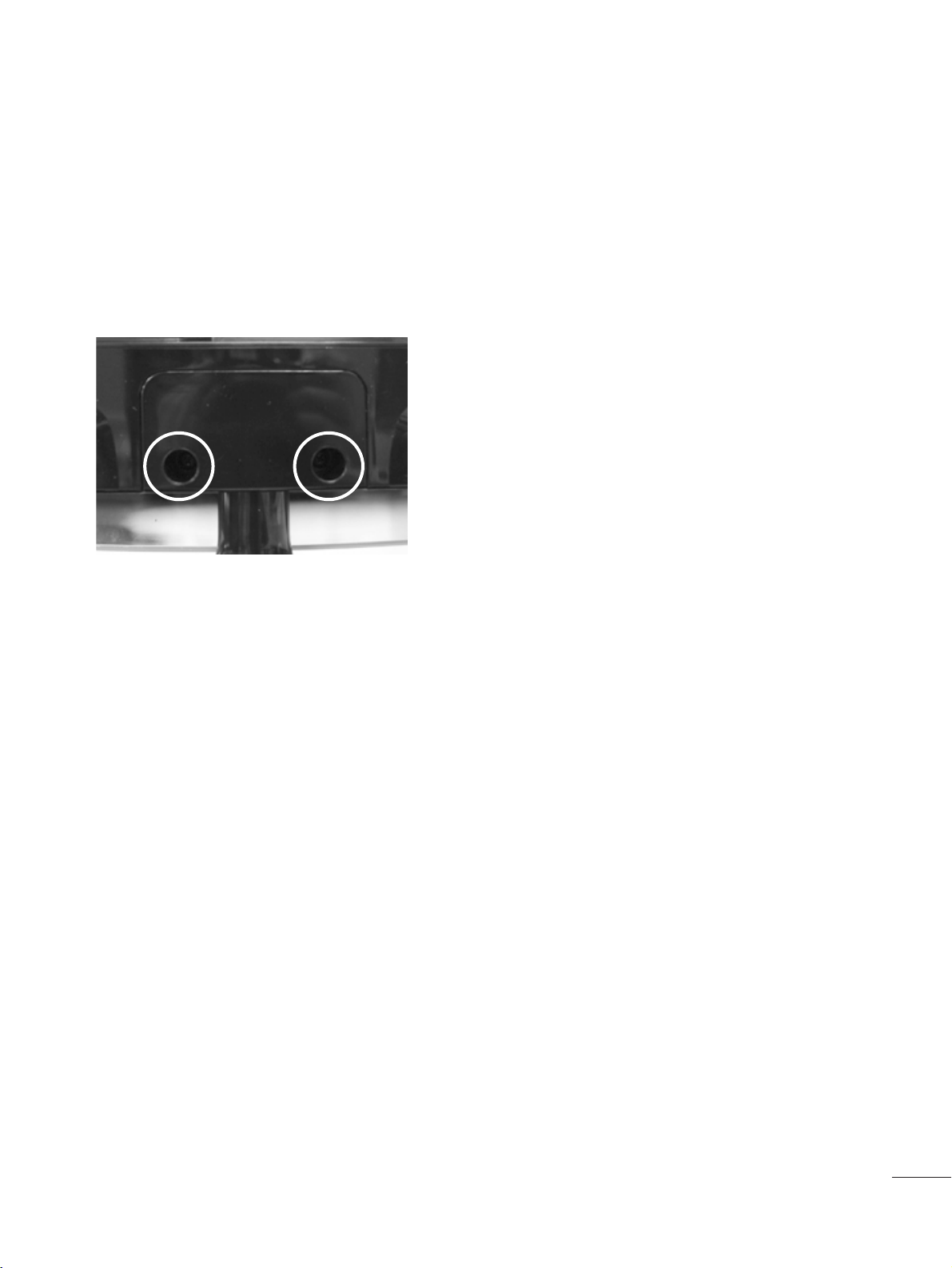
DETACHING STAND BODY
1. Remove the screw 2 point.
2. Pull the stand body.
■
The image shown may be somewhat different from your set.
■
Remove the Stand Body in the same way as the following when using it as a Wall Hook.
66
PREPARATION
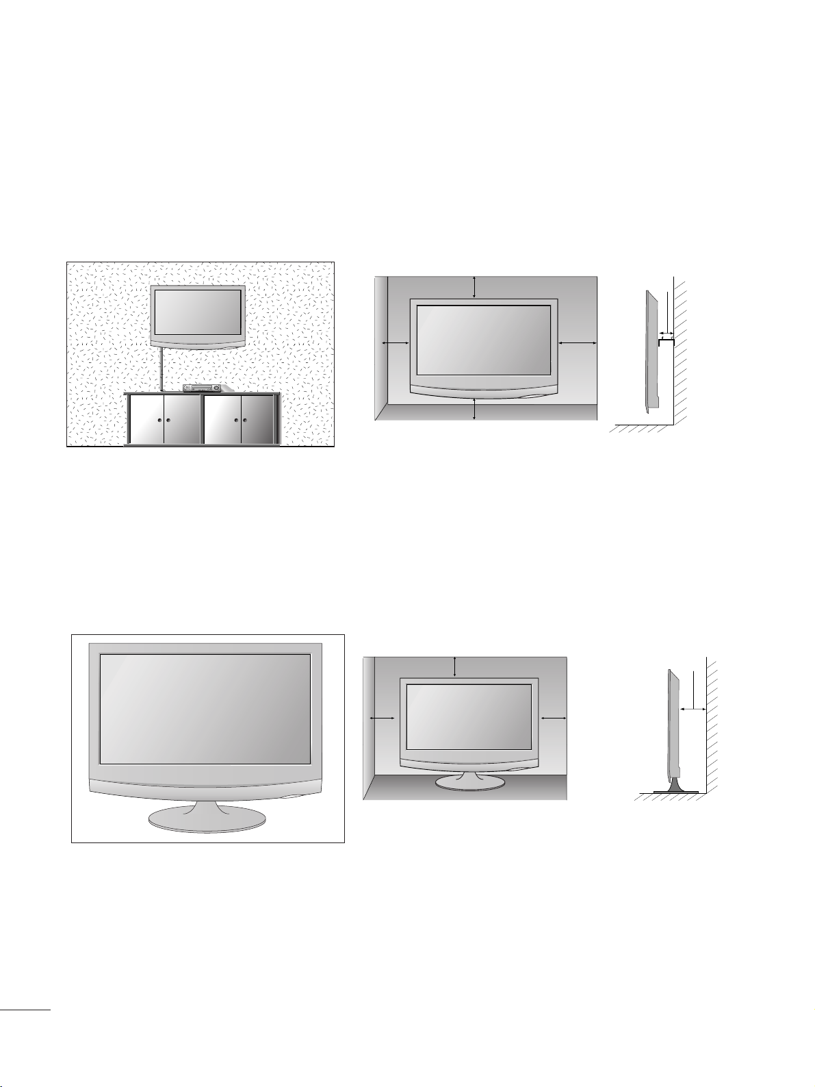
DESKTOP PEDESTAL INSTALLATION
For proper ventilation, allow a clearance of 10 cm on each side and from the wall.
10 c m
10 c m
10 c m
10 c m
WALL MOUNT: HORIZONTAL INSTALLATION
For proper ventilation, allow a clearance of 10 cm on each side and from the wall. Detailed installation
instructions are available from your dealer, see the optional Tilt Wall Mounting Bracket Installation and
Setup Guide.
10 c m
10 c m
10 cm 10 cm
10 c m
77
PREPARATION
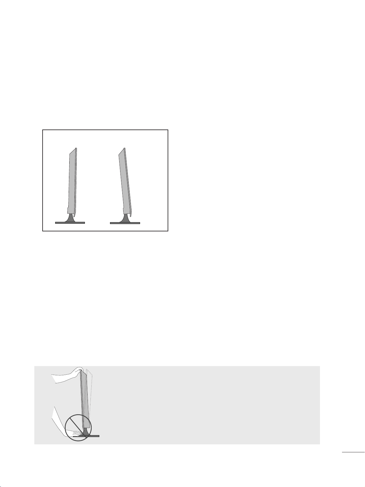
POSITIONING YOUR DISPLAY
■
The image shown may be somewhat different from your set.
Adjust the position of the panel in various ways for maximum comfort.
•• TTiilltt rr aann ggee
LOCATION
Position your set so that no bright light or sunlight falls directly onto the screen. Care should be taken not to expose
the set to any unnecessary vibration, moisture, dust or heat. Also, ensure that the set is placed in a position to allow a
free flow of air. Do not cover the ventilation openings on the back cover.
If you intend to mount the set to a wall, attach Wall mounting interface (optional parts) to the back of the set.
When you install the set using the wall mounting interface (optional parts), attach it carefully so it will not drop.
- Be sure to use screws and a wall mount that meet VESA standards.
- Using screws longer than those recommended might damage the product.
- Using screws that do not meet VESA standards might either damage the product or result in it coming away from the
wall. We will not be held responsible for any damage resulting from failure to follow these instructions.
< Screw Mounting Interface Dimension >
100mm x 100mm hole spacing
-5
°
15
°
WWaarr nniinngg ::
When adjusting the angle of the screen,do not put your
finger(s)in between the head of the monitor and the stand
body.You can hurt your finger(s).
88
PREPARATION
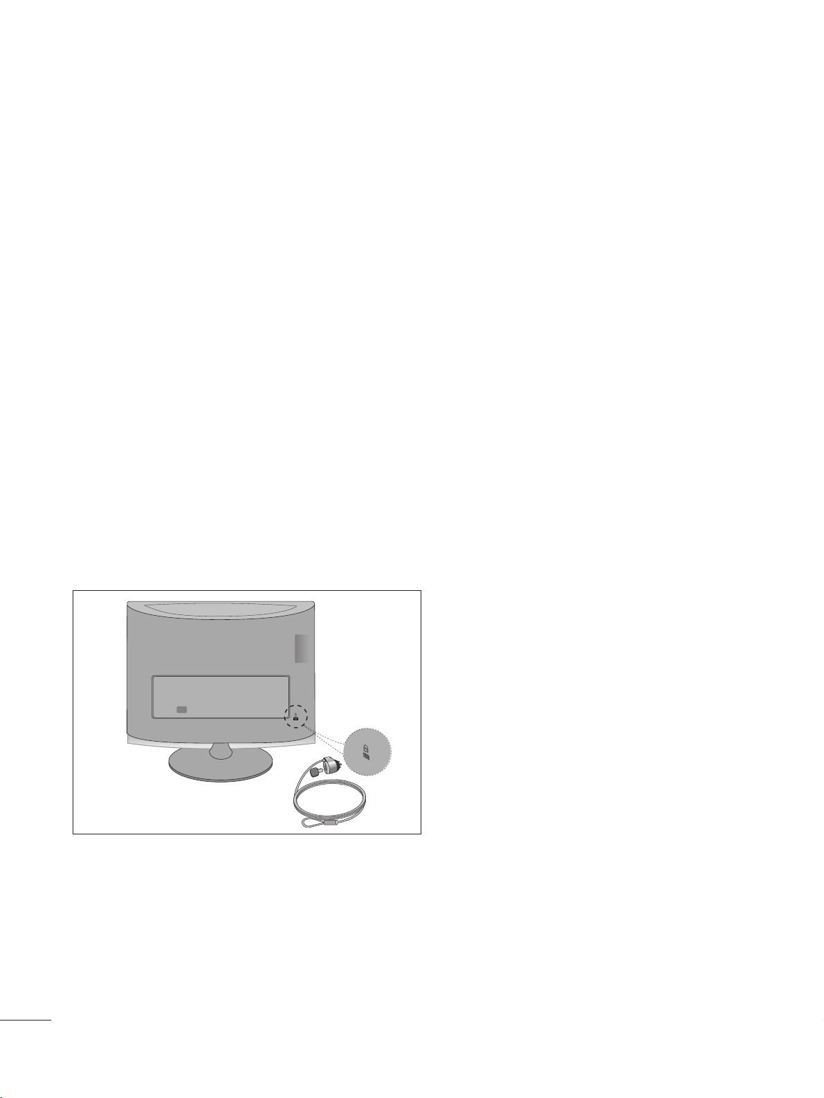
KENSINGTON SECURITY SYSTEM
- The product is equipped with a Kensington Security System connector on the back panel. Connect the
Kensington Security System cable as shown below.
- For detailed installation and use of the Kensington Security System, refer to the user’s guide provided with the
Kensington Security System.
For further information, contact
hhttttpp::////wwwwww ..kk eenn ssiinngg ttoonn ..cc oo mm
, the internet homepage of the Kensington
company. Kensington sells security systems for expensive electronic equipment such as notebook PCs and
LCD projectors.
NOTE
- The Kensington Security System is an optional accessory.
NOTES
a. If the product feels cold to the touch, there may be a small “flicker” when it is turned on.
This is normal, there is nothing wrong with product.
b. Some minute dot defects may be visible on the screen, appearing as tiny red, green, or blue spots. However,
they have no adverse effect on the monitor's performance.
c. Avoid touching the LCD screen or holding your finger(s) against it for long periods of time.
Doing so may produce some temporary distortion effects on the screen.
99
ANTENNA/
CABLE IN
ANTENNA/
CABLE IN
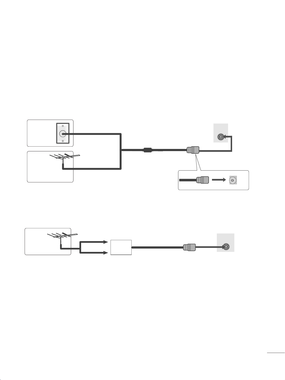
EXTERNAL EQUIPMENT SETUP
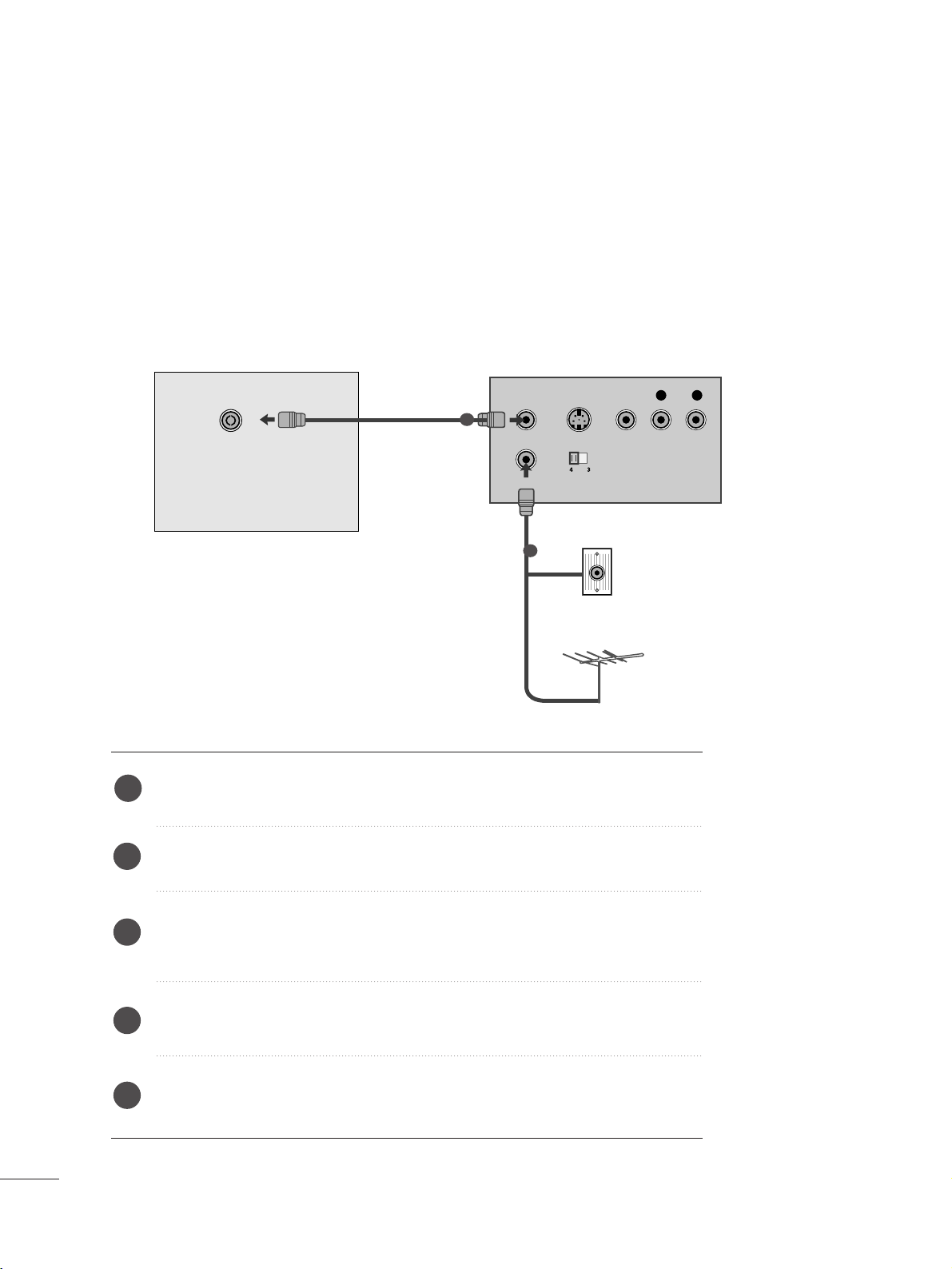
■
For optimum picture quality, adjust antenna direction.
■
An antenna cable and converter are not supplied.
■
To prevent equipment damage, never plug in any power cords until you have finished connecting all equipment.
Multi-family Dwellings/Apartments
(Connect to wall antenna socket)
Single-family Dwellings /Houses
(Connect to wall jack for outdoor antenna)
Outdoor
Antenna
(VHF, UHF)
Wal l
Antenna
Socket
RF Coaxial Wire (75 ohm)
ANTENNA CONNECTION
Antenna
UHF
Signal
Amplifier
VHF
■
In poor signal areas, to get better picture quality, install a signal amplifier to the antenna as shown above.
■
If signal needs to be split for two TVs, use an antenna signal splitter for connection.
1100
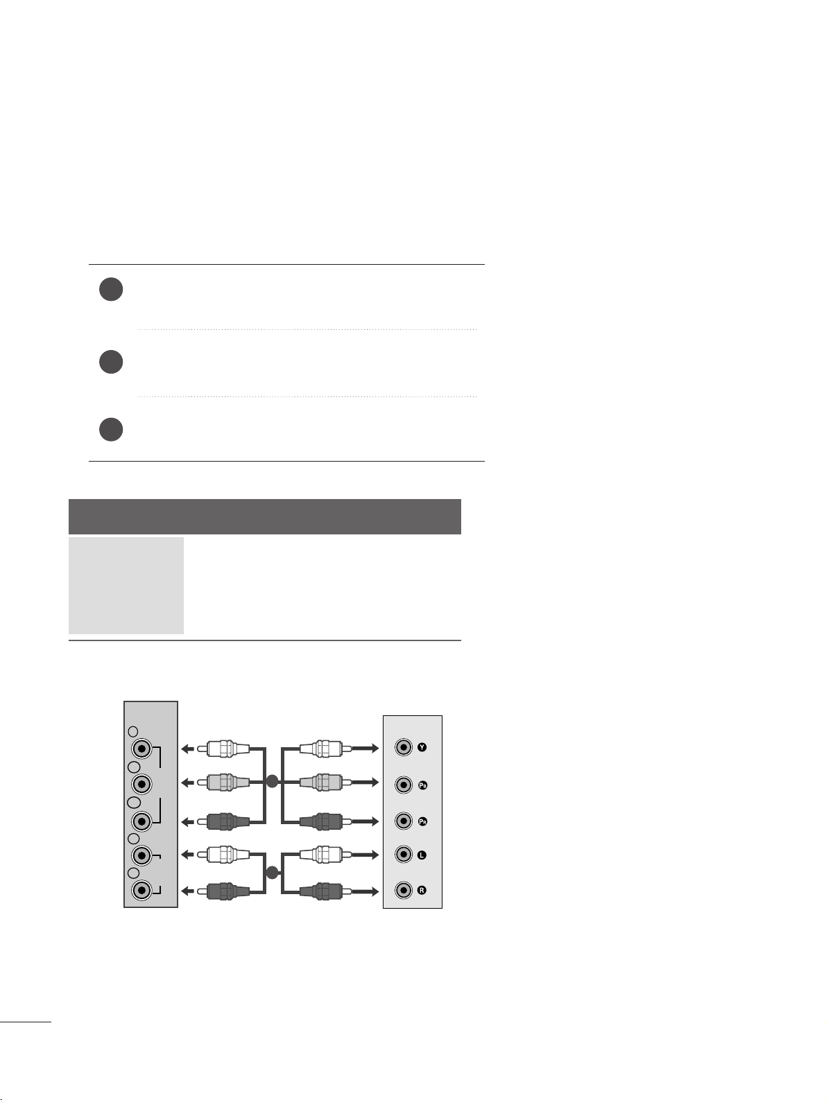
EXTERNAL EQUIPMENT SETUP
Connect the SET-TOP outputs to the
CCOO MMPPOO NNEENNTT IINN
VV IIDDEE OO
sockets (Y P
B PR) on the set.
Connect the audio cable from the SET-TOP to
CC OO MM PPOO--
NN EENNTT IINN AAUUDD IIOO
sockets of the set.
Press the
IINN PP UUTT
button to select
CCoommppoonneenntt..
2
3
1
HD RECEIVER SETUP
■
To prevent the equipment damage, never plug in any power cords until you have finished connecting all equipment.
■
The image shown may be somewhat different from your set.
When connecting with a component cable
Signal
480i/576i
480p/576p
720p/1080i
10 8 0 p
Component
Yes
Yes
Yes
Yes
HDMI
No
Yes
Yes
Yes
VIDEO
COMPONENT
IN
AUDIO
Y
P
B
P
R
L
R
1
2
1111
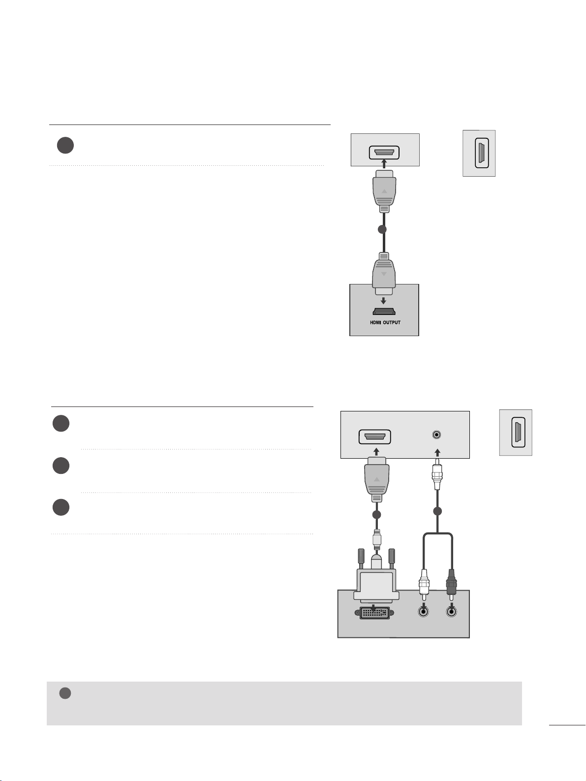
EXTERNAL EQUIPMENT SETUP
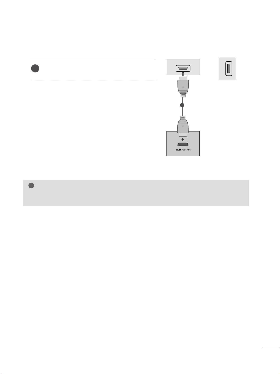
When connecting with a HDMI
Connect the HDMI output of the digital set-top box to the
HHDDMMII IINN
jack on the set.
1
Connect the digital set-top box to
HHDDMMII IINN
jack on
the set.
Connect the audio output of the digital set-top box to
the
AAUU DD IIOO IINN (( RRGGBB//DDVVII))
jack on the set.
Turn on the digital set-top box. (Refer to the owner’s
manual for the digital set-top box.
)
2
3
1
When connecting with a HDMI to DVI cable
NOTE
!
G
HDMI Input does not support PC mode. If it is connected PC, the screen may not be displayed properly.
or
HDMI IN
1
1
HDMI IN
2
HDMI IN
2
DVI OUTPUT
AUDIO
RL
AUDIO IN
(RGB/DVI)
HDMI IN
1
1
2
or
1122
EXTERNAL EQUIPMENT SETUP
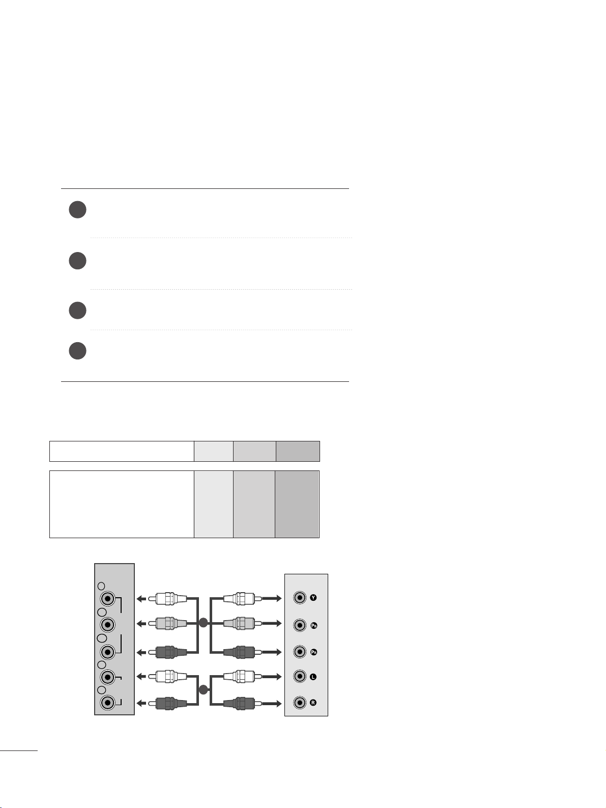
DVD SETUP
When connecting with a component cable
Component Input ports
To get better picture quality, connect a DVD player to the component input ports as shown below.
Component ports on the set
YPBP
R
Video output ports
on DVD player
Y
Y
Y
Y
P
B
B-Y
Cb
Pb
P
R
R-Y
Cr
Pr
Connect the video output sockets (Y P
B PR) of the DVD to
the
CCOO MMPP OONN EENNTT II NN VVIIDDEE OO
sockets (Y P
B PR) of the set.
Connect the audio cable from the DVD to
CCOO MM PP OONNEENNTT
IINN AA UUDDII OO
sockets of the set.
Press the
IINN PP UUTT
button to select
CCoommpp oo nneenntt
.
Press the
PPLL AAYY
button on the DVD.
The DVD playback picture appears on the screen.
2
3
4
1
1
2
COMPONENT
IN
Y
P
B
VIDEO
P
R
L
AUDIO
R
1133
EXTERNAL EQUIPMENT SETUP
When connecting HDMI cable
Connect the HDMI output of the DVD to the
HHDDMMII IINN
jack on the set.
1
G Set can receive the video and audio signal simultaneously by using a HDMI cable.
G If the DVD player does not support Auto HDMI, you need to set the DVD output resolution appropriately.
NOTE
!
or
HDMI IN
1
1
HDMI IN
2
1144
EXTERNAL EQUIPMENT SETUP
VCR SETUP
■
To avoid picture noise (interference), leave an adequate distance between the VCR and set.
■
Typically a still picture is shown on the VCR. If a user uses 4:3 picture format for a long time, an afterimage
may remain on the sides of the screen.
OUTPUT
SWITCH
ANT IN
R
S-VIDEO VIDEO
ANT OUT
L
ANTENNA/
CABLE IN
Wall Jack
Antenna
1
2
When connecting with an antenna
Connect the RF out socket of the VCR to the aerial socket of the set.
Connect the aerial cable to the RF aerial in socket of the VCR.
Store the VCR channel on a desired programme number using the ‘Manual
programme tuning’ section.
Select the programme number where the VCR channel is stored.
Press the
PPLLAAYY
button on the VCR.
1
2
3
4
5
1155
EXTERNAL EQUIPMENT SETUP
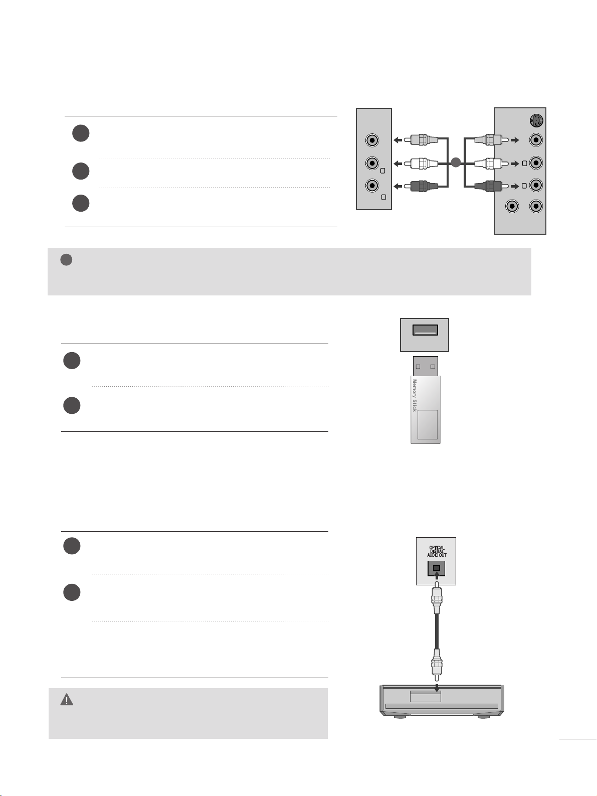
WWhheenn ccoonnnneeccttiinngg wwiitthh aa RRCCAA ccaabbllee
Connect the audio/video out sockets of the VCR to
AUDIO/VIDEO in sockets of the set.
Press the INPUT button to select AV.
Press the PLAY button on the VCR.
The VCR playback picture appears on the screen.
2
3
1
NOTE
!
G
If you have a mono VCR, connect the audio cable from the VCR to the AUDIO L/MONO jack of the set.
VIDEO ANT IN
ANT OUT
S-VIDEO
L
R
VIDEO AUDIO
(MONO)
L
R
AV IN
1
Connect the USB device to the
UUSSBB IINN
jacks on the
side of set.
After connecting the
UUSSBB IINN
jacks, you use the
UUSS BB
function. (
G
pp ..88 00
)
2
1
USB SETUP
USB IN
Connect one end of an optical cable to the TV Digital
Audio (Optical)Output port.
Connect the other end of the optical cable to the digital audio (Optical)input on the audio equipment.
Set the
““TT VV SSppeeaakkeerr ooppttiioonn -- OOffff ””
in the AUDIO
menu.(
G
pp..6633
). Refer to the external audio equipment
instruction manual for operation.
Sending the TV’s audio signal to external audio equipment via the Digital Audio Output (Optical) port.
If you want to enjoy digital broadcasting through 5.1-channel speakers, connect the OPTICAL DIGITAL AUDIO
OUT terminal on the back of TV to a DVD Home Theater (or amp).
2
1
DIGITAL AUDIO OUT SETUP
G
Do not look into the optical output port. Looking at the
laser beam may damage your vision.
CAUTION
1166
EXTERNAL EQUIPMENT SETUP
PC SETUP
This product provides Plug and Play capability, meaning that the PC adjusts automatically to the set's settings.
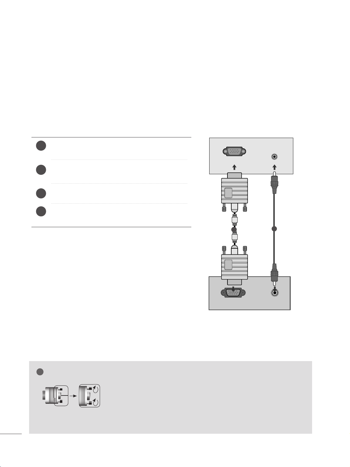
When connecting with a D-sub 15 pin cable
4
Connect the signal cable from the monitor output socket of
the PERSONAL COMPUTER to the PC input socket of the set.
Connect the audio cable from the PC to the
AAUU DD IIOO IINN
(( RRGG BB//DDVVII))
sockets of the set.
Press the INPUT button to select
RR GGBB
.
Switch on the PC, and the PC screen appears on the set.
The set can be operated as a PC monitor.
2
3
1
RGB OUTPUT
AUDIO
AUDIO IN
(RGB/DVI)
RGB IN (PC)
1
2
NOTE
!
G
You must use shielded signal interface cables (D sub 15 pin cable, DVI cable) with ferrite cores to maintain
standard compliance for the product.
G
Connect the signal input cabel and tighten the screws by turning them clockwise.
1177
EXTERNAL EQUIPMENT SETUP
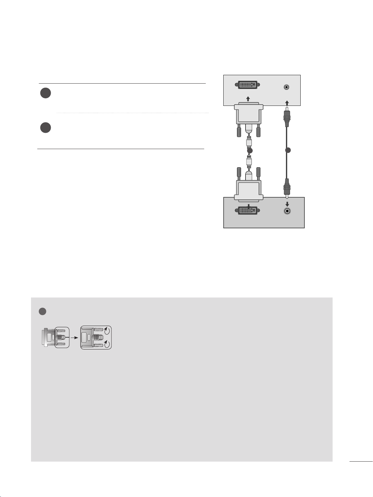
When connecting with a DVI cable
Connect the DVI output of the PC to the
DDVV II--DD IINN
jack on the set.
Connect the audio cable from the PC to the
AAUU DDIIOO
IINN ((RR GG BB//DD VVII ))
sockets of the set.
2
1
NOTE
!
G
If the set is cold, there may be a small “flicker” when the
set is switched on. This is normal, there is nothing
wrong with the set.
G
If possible, use the 1920x1080 @ 60 Hz video mode
to obtain the best image quality for your LCD monitor.
If used with other resolutions, some scaled or
processed pictures may appear on the screen. The set
has been preadjusted to the mode 1920x1080 @ 60
Hz.
G
Some dot defects may appear on the screen, like Red,
Green or Blue spots. However, this will have no impact
or effect on the monitor performance.
G
Do not press the LCD screen with your finger for a long
time as this may produce some temporary distortion
effects on the screen.
G
Avoid keeping a fixed image on the set’s screen for prolonged periods of time. The fixed image may become
permanently imprinted on the screen; use a screen
saver when possible.
AUDIO
DVI OUTPUT
AUDIO IN
(RGB/DVI)
DVI-D IN (PC)
1
2
G
Connect the signal input cabel and tighten the screws by turning them
clockwise.
1188
EXTERNAL EQUIPMENT SETUP
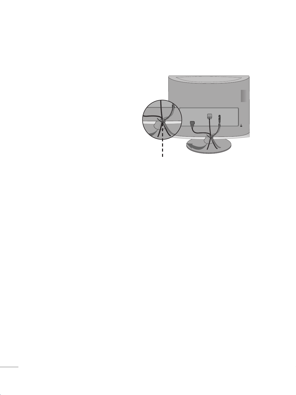
Tie cables together with a cable tie as shown in the
illustration.
BACK COVER FOR WIRE ARRANGEMENT
Cable tie
R
R
1199
EXTERNAL EQUIPMENT SETUP
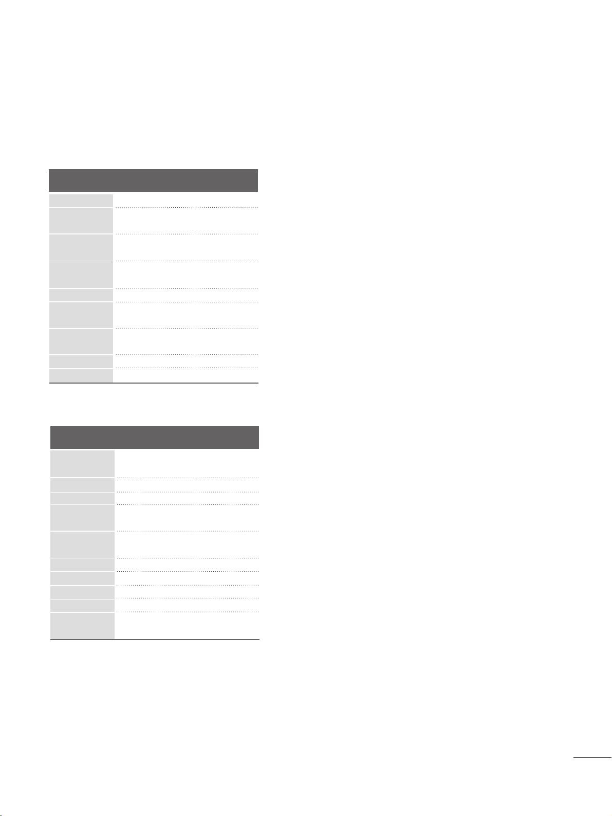
RGB/DVI[PC]
HDMI[DTV] (Not Support PC)
60
60
50
50
60
60
60
60
50
24
30
50
60
60
31 . 4 6 9
31 . 5
31 . 2 5
37.5
44.96
45
33 .72
33 .75
28. 125
27
33 .75
56.25
67.43
67.5
Resolution
720x480/60p
720x576/50p
1280x720/60p
1280x720/50p
Horizontal
Frequency(kHz)
Vertical
Frequency(Hz)
1920x1080/60i
1920x1080/50i
1920x1080/24p
1920x1080/30p
1920x1080/50p
Resolution
640x480
800x600
720x400
1024x768
Horizontal
Frequency(kHz)
Vertical
Frequency(Hz)
31 . 4 6 8 70
31 . 4 6 9 6 0
37.500 75
37.879 60
46 .875 75
48.363 60
60.123 75
67.500 75
63.981 60
79. 976 75
64.674 60
65.290 60
75.000 60
66.587 60
1280x1024
1152x864
1680x1050
1920x1080
1600x1200
1920x1080/60p
SUPPORTED DISPLAY RESOLUTION
2200
WATCHING TV /PROGRAMME CONTROL
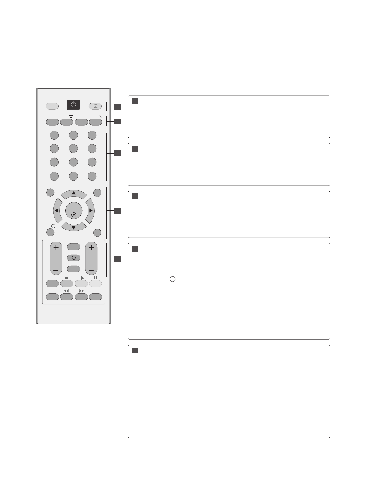
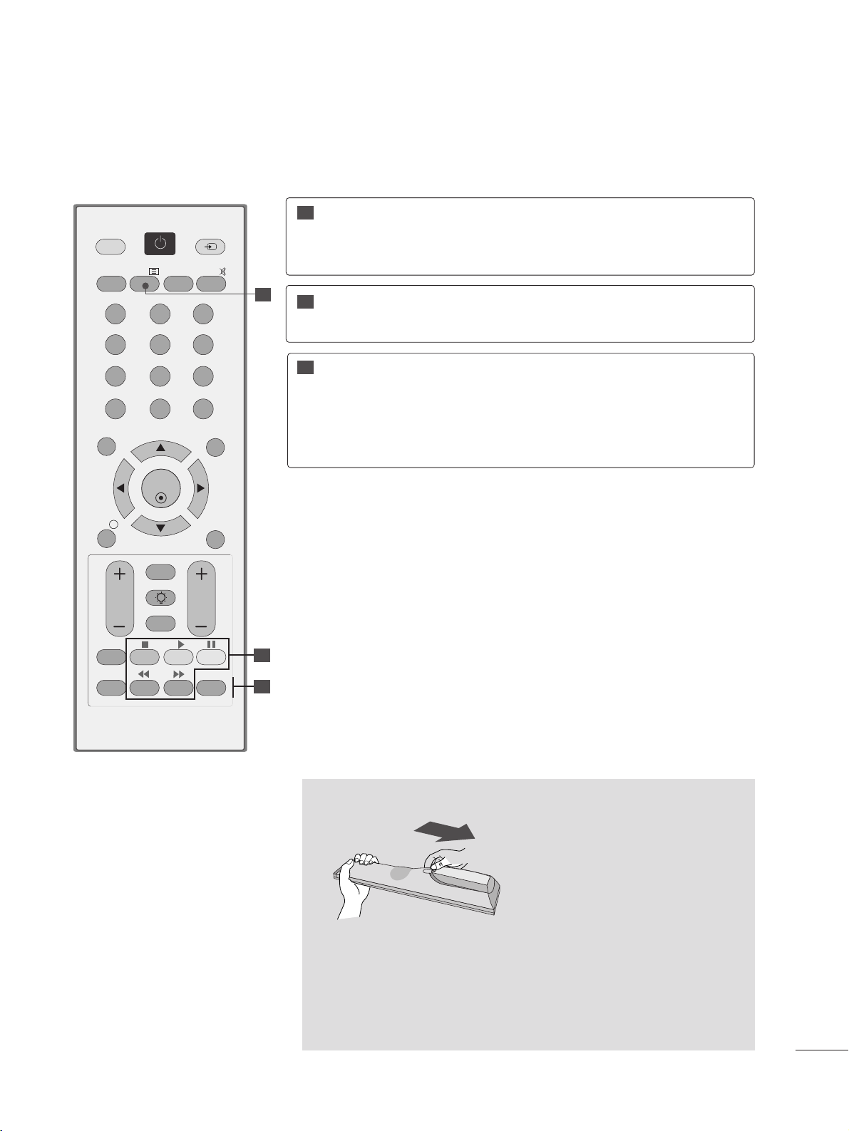
REMOTE CONTROL KEY FUNCTIONS
When using the remote control, aim it at the remote control sensor on the set.
OK
MENU EXIT
GUIDE
123
456
789
0
Q.VIEW
LIST
TV/PC INPUT
POWER
VOL PR
I/II
MUTE
TEXT
RETURN
LIGHTING
FAV
INFO
i
TV/RADIO
Q.MENU
T.OPT MARK
SUBTITLE
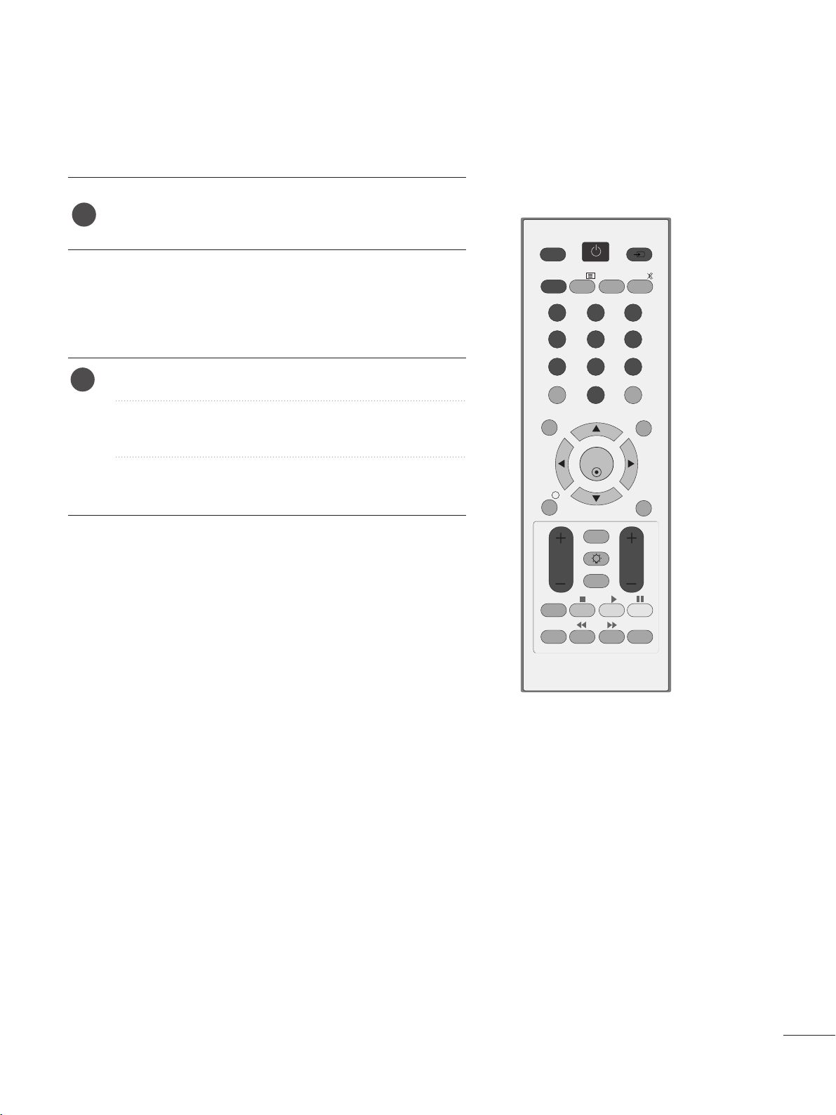
POWER
TV/PC
INPUT
Switches the set on or off.
Selects TV or PC mode.
External input mode rotates in regular sequence.
TV/RADIO
I/II
MUTE
Selects Radio or TV channel.
Selects the sound output.(Refer to the p.64)
Switches the sound on or off.
0 to 9
number button
LIST
Q.VIEW
Selects a programme.
Selects numbered items in a menu.
Displays the programme table.(Refer to the p.35)
Returns to the previously viewed programme.
MENU
EXIT
INFO i
GUIDE
THUMBSTICK
(Up/Down/Left/Right)
OK
Selects a menu. (Refer to the p.25)
Clears all on-screen displays.
Shows the present screen information.
Shows programme schedule.(Refer to the p.36 to 38 )
Allows you to navigate the on-screen menus and adjust
the system settings to your preference.
Accepts your selection or displays the current mode.
VOLUME UP
/DOWN
RETURN
LIGHTING
FAV
Programme
UP/DOWN
Adjusts the volume.
Allows the user to move back one step in an interactive application, EPG or other user interaction function.
Press the Lighting button to turn the decoration lighting on/off.
Displays the selected favourite programme.(Refer to the p.35)
Selects a programme.
11
11
22
33
44
55
22
33
44
55
2211
WATCHING TV /PROGRAMME CONTROL
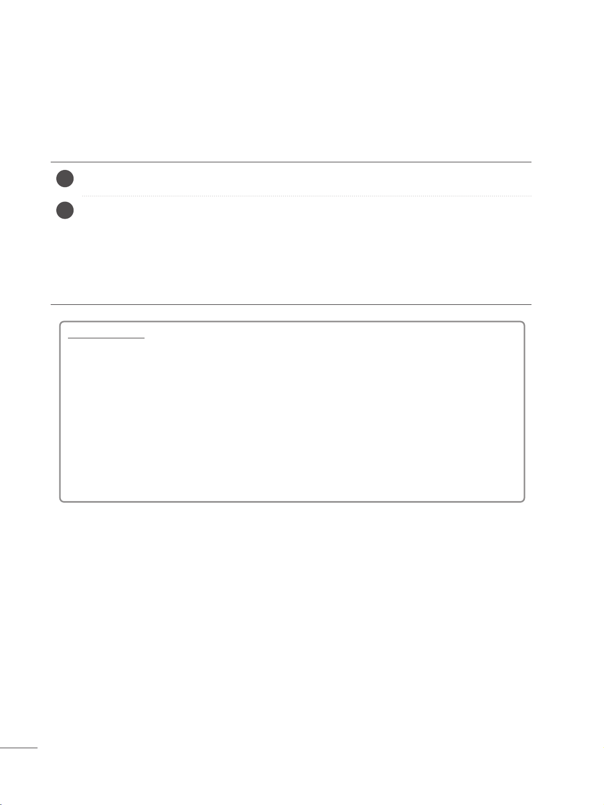
Installing Batteries
■
Open the battery compartment cover on the back and install the
batteries matching correct polarity (+ with +, - with -).
■
Install two 1.5V AAA batteries. Don’t mix old or used batteries with
new ones.
■
Close cover.
USB Menu
control buttons
Controls USB menu (Photo List and Music
List)
(Refer to the p.80)
TELETEXT
BUTTONS
These buttons are used for teletext.
For further details, see the ‘Teletext’ section.
(Refer to the p.88 to 89)
11
22
33
Q.MENU
MARK
Select the desired quick menu source.
(Refer to the p.24)
Check and un-check programmes in the recorded set
menu.
OK
MENU EXIT
GUIDE
123
456
789
0
Q.VIEW
LIST
TV/PC INPUT
POWER
VOL PR
I/II
MUTE
TEXT
RETURN
LIGHTING
FAV
INFO
i
TV/RADIO
Q.MENU
T.OPT MARK
SUBTITLE
11
22
33
2222
WATCHING TV /PROGRAMME CONTROL
TURNING ON THE TV
- When your TV is turned on, you will be able to use its features.
Firstly,connect the power cord correctly and check the main power( r / I )on the TV.
SSeett IIDD :: OOffff
In standby mode to turn TV on, press the INPUT or PR
D
//
E
button on the TV or press the POWER button on the
remote control and the TV will switch on.
SSeett IIDD :: OOnn
In standby mode to turn TV on,pr ss the INPUT or PR
D
//
E
button on the TV or press the POWER, INPUT, PR
D
//
E
or NUMBER button on the remote control and the TV will switch on.
2
1
Initializing setup
Note:
a. If you close without completing the initial setting, the Initial Setting menu can be displayed again.
b. Press the RETURN button to change the current OSD to the previous OSD.
c. "
HHoommee UUssee
” mode is the optimal setting for home environments, and is the TV's default mode.
d. "
SSttoorree DDeemmoo
"mode is the optimal setting for store environments. If a user modifies image quality data,
“
SSttoorree DDeemmoo
” mode initializes the product to the image quality set by us after a certain period of time.
e. The mode (
HHoommee UUssee, SSttoorree DDeemmoo
) can be changed by executing
MMooddee SSeettttiinngg
in the
OOPPTTIIOONN
menu.
If the OSD (On Screen Display) is displayed on the screen after turning on the TV, you can adjust
the
MM oo dd ee SSeetttt iinn gg, AAuu ttoo ttuu nniinngg
.
2233
WATCHING TV /PROGRAMME CONTROL
OK
MENU EXIT
GUIDE
123
456
789
0
Q.VIEW
LIST
TV/PC INPUT
POWER
VOL PR
I/II
MUTE
TEXT
RETURN
FAV
INFO
i
TV/RADIO
Q.MENU
T.OPT MARK
SUBTITLE
LIGHTING
PROGRAMME SELECTION
Press the
PPRR ++ or--
or NUMBER buttons to select a pro-
gramme number.
1
VOLUME ADJUSTMENT
Press the VOL
++ or--
button to adjust the volume.
If you want to switch the sound off, press the MUTE
button.
You can cancel this function by pressing the MUTE,
VOL
++ or--
, or I/II button.
1
2244
WATCHING TV /PROGRAMME CONTROL
• Press the RETURN button to move to the previous menu screen.
•
AAssppee cc tt RRaattiioo
: Selects your desired picture format.
For Zoom Setting, select 14:9, Zoom and Cinema
Zoom in Ratio Menu. After completing Zoom Setting,
the display goes back to Q.Menu.
•
PPiiccttuu rree MMooddee
: Selects your desired Picture Mode.
•
SSoouunn dd MM oo dd ee
: It is a feature to automatically set the
sound combination which it deems the best for the
images being watched. Selects your desired Sound
Mode.
•
AAuuddiioo
: Selects the sound output.
•
SSlleeeepp TTiimm eerr
: Sets the sleep timer.
•
UUSSBB EEjjeecctt
: Selects “USB Eject” in order to eject USB
device.
QUICK MENU
Display each menu.
Select your desired Source.
Your TV's OSD (On Screen Display) may differ slightly from that shown in this manual.
Q.Menu (Quick Menu) is a menu of features which users might use frequently.
1
Q. MENU
3
2
OK
OK
or
QQ.. MMeennuu
CCll oo ss ee
11 66 ::99
ZZ oo oo mm SS ee ttttiinngg
SS tt aann dd aarrdd
SS tt aann dd aarrdd
LL++ RR
OOffff
EE jjeecctt
Aspect Ratio
Picture Mode
Sound Mode
Audio
Sleep Timer
USB Eject
2255
WATCHING TV /PROGRAMME CONTROL
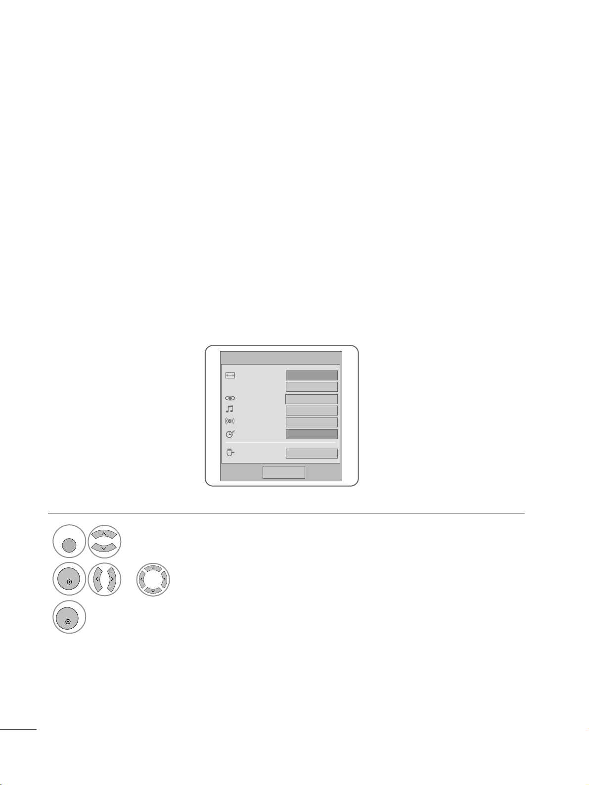
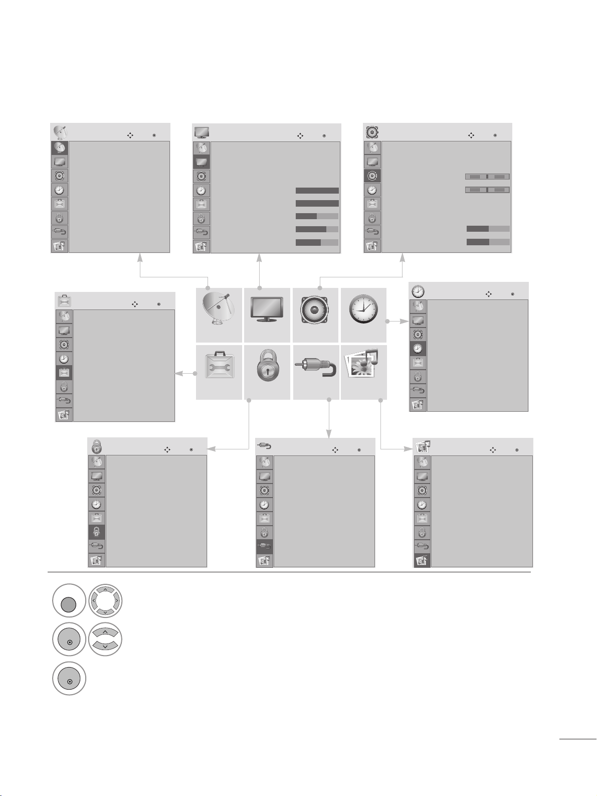
ON SCREEN MENUS SELECTION AND ADJUSTMENT
Your set's OSD (On Screen Display)may differ slightly from what is shown in this manual.
SETUP
OPTION LOCK INPUT USB
AUDIO TIME
PICTURE
1
Display each menu.
2
Select a menu item.
3
Move to the pop up menu.
MENU
OK
OK
• Press the MENU or EXIT button to close the menu window.
• Press the RETURN button to move to the previous menu screen.
Auto tuning
Manual tuning
Programme Edit
Software Update : On
Diagnostics
SETUP
Move
OK
Clock
Off Time : Off
On Time : Off
Sleep Timer : Off
Auto Off : On
TIME
Move
OK
Subtitle : Off
Input Label
Key Lock : Off
Set ID : Off
Power Indicator
DDC CI : On
Mode Setting : Home Use
Factory Reset
OPTION
Move
OK
Lock System : Off
Set Password
Block Programme
Parental Guidance : Off
Input Block
LOCK
Move
OK
Antenna
AV
Component
RGB
HDMI 1
HDMI 2
DVI
INPUT
Move
OK
Photo List
Music List
USB
Move
OK
Auto Volume : Off
Clear Voice II : Off
• Level 3
Balance 0
Sound Mode : Standard
• Treble 50
• Bass 50
AUDIO
Move
OK
-+
LR
E
Aspect Ratio : 16:9
Auto Bright : Off
Picture Mode : Vivid
• Backlight 100
• Contrast 100
• Brightness 50
• Sharpness 70
• Colour 60
PICTURE
Move
OK
E
2266
WATCHING TV /PROGRAMME CONTROL
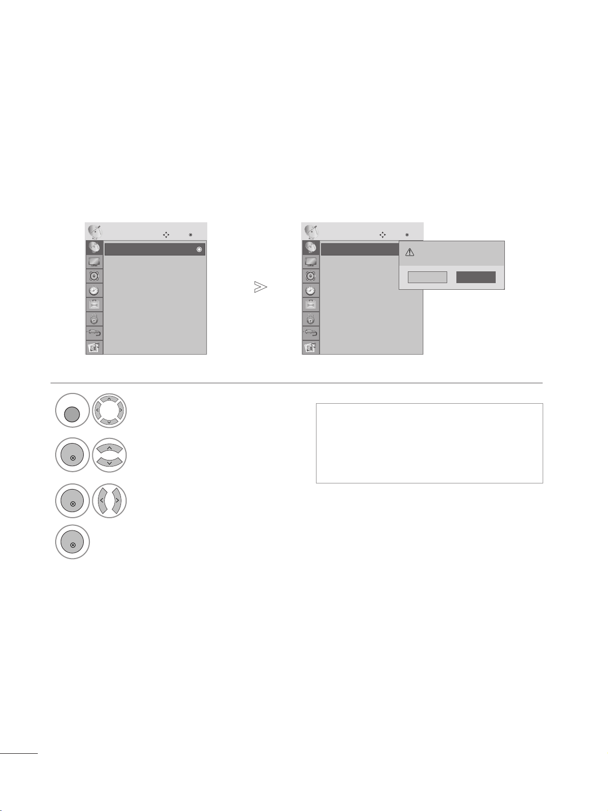
Use this to automatically find and store all available programmes.
When you start auto programming in digital mode, all previously stored service information will be deleted.
AUTO PROGRAMME TUNING
• Use NUMBER buttons to input a 4-digit
password in Lock System ‘On’.
• If you wish to keep on auto tuning, select
YES using the
F G
button. Then, press the
OK button. Otherwise, select NO.
Select
SSEE TTUU PP
.
2
Select
AAuu ttoo TTuu nniinngg
.
3
Select
YY ee ss
.
4
Run Auto tuning.
1
•
Press the MENU or EXIT button to close the menu window.
• Press the RETURN button to move to the previous menu screen.
Auto tuning
Manual tuning
Programme Edit
Software Update : On
Diagnostics
SETUP
Move
OK
AAuu tt oo ttuunn iinn gg
Auto tuning
Manual tuning
Programme Edit
Software Update : On
Diagnostics
SETUP
Move
OK
AAuu tt oo ttuunn iinn gg
All service-information will be updated.
Continue?
Yes No
MENU
OK
OK
OK
2277
WATCHING TV /PROGRAMME CONTROL
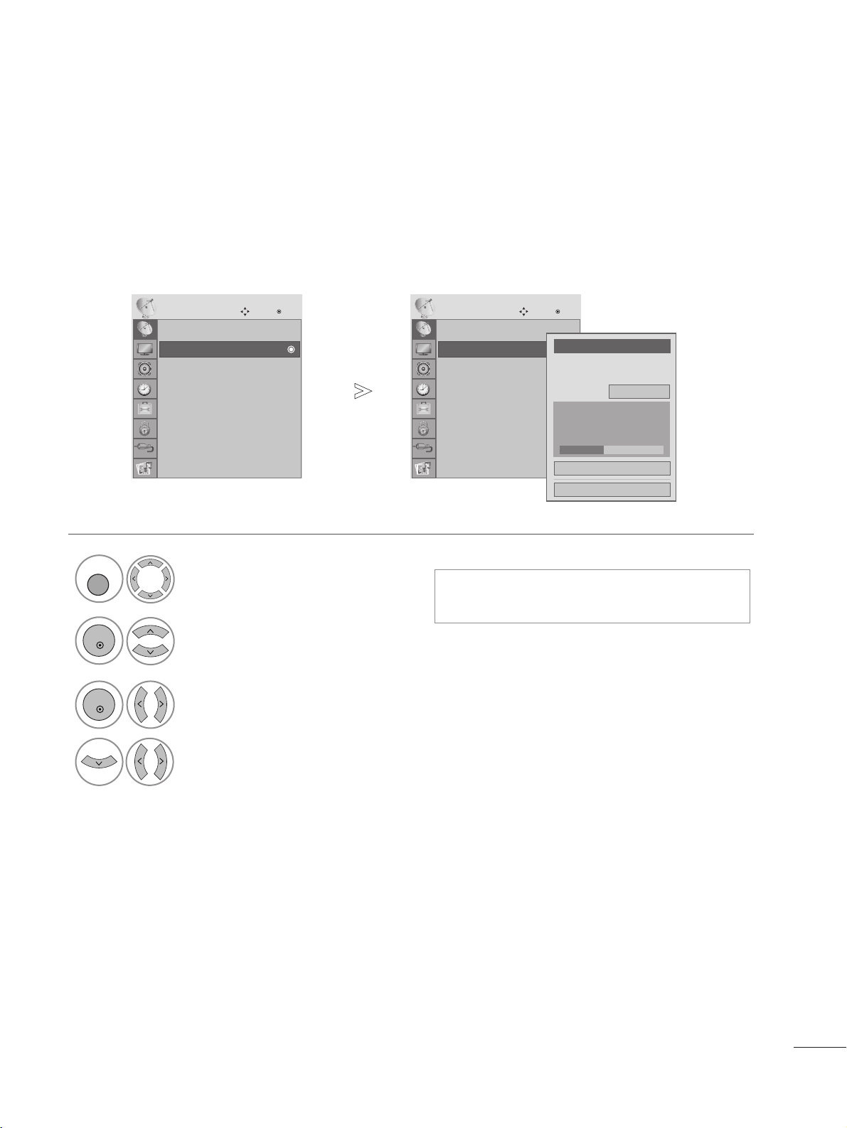
Manual Tuning lets you manually add a programme to your programme list.
MANUAL PROGRAMME TUNING
(IN DIGITAL MODE)
•
Use NUMBER buttons to input a 4-digit
password in Lock System ‘On’.
Select
SSEE TTUU PP
.
2
1
Select
MM aann uuaall TTuu nniinngg
.
3
Select
DDTTVV
.
4
Select the desired channel number.
• Press the MENU or EXIT button to close the menu window.
• Press the RETURN button to move to the previous menu screen.
Auto tuning
Manual tuning
Programme Edit
Software Update : On
Diagnostics
SETUP
Move
OK
MMaannuu aall tt uu nniinngg
Auto tuning
Manual tuning
Programme Edit
Software Update : On
Diagnostics
SETUP
Move
OK
MMaannuu aall tt uu nniinngg
Your receiver will add this
channel to your channel list.
UHF CH.
Bad Normal Good
F
DTV
G
30
Add
Close
MENU
OK
OK
2288
WATCHING TV /PROGRAMME CONTROL
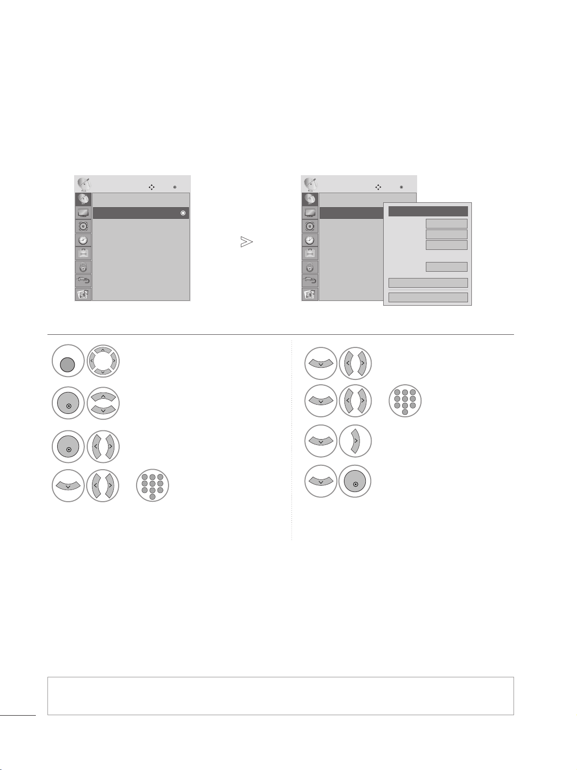
Manual Tuning lets you manually tune and arrange the stations in whatever order you desire.
MANUAL PROGRAMME TUNING (IN ANALOGUE MODE)
• Use NUMBER buttons to input a 4-digit password in Lock System ‘On’.
• To store another channel, repeat steps 4 to 9.
Select
SSEE TTUU PP
.
2
Select
MM aann uuaall TTuu nniinngg
.
3
Select
TT VV
.
4
Select the desired programme number on.
5
Select
VV // UUHHFF
or
CC aa bb ll ee
.
7
Start searching.
8
Select
SStt oo rree
.
or
6
Select the desired
channel number.
or
1
•
Press the MENU or EXIT button to close the menu window.
• Press the RETURN button to move to the previous menu screen.
Auto tuning
Manual tuning
Programme Edit
Software Update : On
Diagnostics
SETUP
Move
OK
MMaannuu aall tt uu nniinngg
Auto tuning
Manual tuning
Programme Edit
Software Update : On
Diagnostics
SETUP
Move
OK
MMaannuu aall tt uu nniinngg
Storage
F
TV
G
1
Band
V/UHF
Channel
F G
Search
1
Name
C 01
Store
Close
MENU
OK
OK
123
456
7809
123
456
7809
OK
2299
WATCHING TV / PROGRAMME CONTROL
You can assign a station name with five characters to each programme number.
A Assigning a station name
Select SETUP.
2
Select Manual Tuning.
3
Select TV.
4
Select Name.
5
Select the position and make
your choice of the second
character, and so on.
You can use the alphabet AAto
ZZ
, the number 00to 99, +/ -, and
space.
6
Select Close.
7
Select Store.
1
•
Press the MENU or EXIT button to close the menu window.
• Press the RETURN button to move to the previous menu screen.
MENU
OK
OK
OK
OK
OK
 Loading...