

LG LXN0356QC Owner’s Manual
TELECOM AIR CONDITIONERS
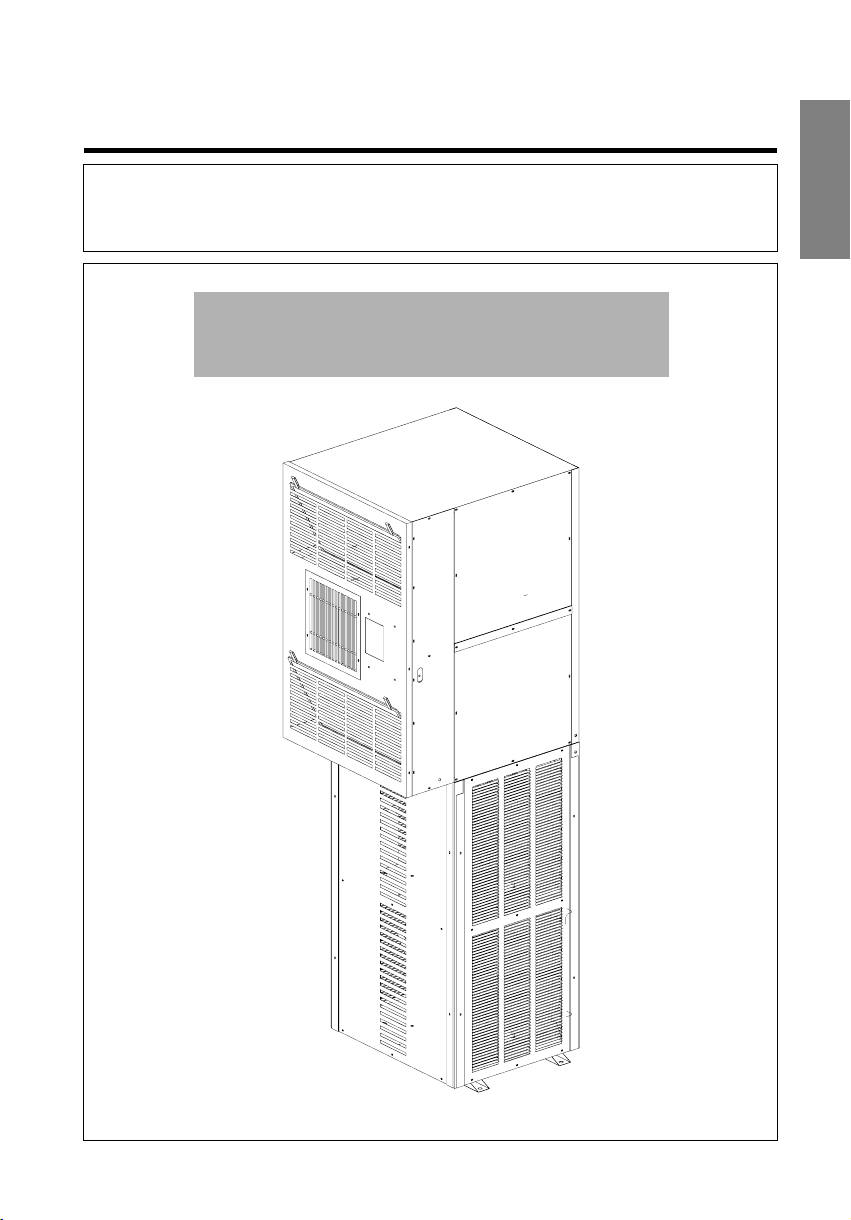
INSTALLATION INSTRUCTIONS
l Please read this instruction sheet completely before installing the product.
l When the power cord is to be replaced, replacement work shall be performed by authorized
personnel only.
l Installation work must be performed in accordance with national wiring standards by authorized
personnel only.
3.0TR SINGLE PHASE: LX-0356QC
3.5TR SINGLE PHASE: LX-0456QC
ENGLISH


INDEX
ENGLISH
1.The following should be always observed for safety ...................
2. Product Specification ..........................................................................
2.1 Product Description .............................................................................
2.2 Inspection ............................................................................................
2.3 Technical specification .......................................................................
3. Installation Standard ..........................................................................
3.1 Pre-check ...........................................................................................
3.2 Levelling of Airconditioner ..................................................................
3.3 Shelter Cut - out sealing ......................................................................
3.4.Condensate Drain Pipe .......................................................................
3.5 Air purging of connecting pipes & Indoor unit ......................................
3.6 Filter Cleaning .....................................................................................
3.7 Installation Drawing - Cases 1& 2 ...............................................
3.8 Installation Drawing - Foundation ......................................................
4. Controller ............................................................................................
4.1 Display & Indicators ...........................................................................
4.2 Pre-Startup instructions ....................................................................
4.3 Operations ...................................................................................
4.4 LCD menu details ........................................................................
5.Trouble Shooting ...............................................................................
5.1 Symptoms & Problems .....................................................................
6.Electrical wiring diagram ..................................................................
6.1 Indoor wiring Diagram .......................................................................
6.2 Outdoor wiring Diagram ....................................................................
6.3 Controller Connection Diagram .........................................................
7.Exploded view .....................................................................................
7.1 indoor unit ..........................................................................................
7.2 Outdoor unit .......................................................................................
7.3 Part List ........................................................................................
4~5
11~14
18~19
20~27
33~34
6
6
6
7
8
8
9
9
9
10
10
15
16
16
17
28
28
29
29
29
30
31
31
32
3
1. The following should be always observed for safety
The supplied unit requires 3 phase supply to operate, so please make sure to have authorised
connection by the supply authority before connecting to the system.
Be sure to read "THE FOLLOWING SHOULD BE ALWAYS OBSERVED FOR SAFETY" before
installing the air conditioner.
Be sure to observe the cautions specified here as they include important items related to safety.
The indications and meanings are as follows.
WARNING
CAUTION
Could lead to death, serious injury, etc.
Could lead to serious injury in particular environments when operated incorrectly.
After reading this manual, be sure to keep it together with the owner's manual in an accessible place.
WARNING
Do not install it yourself (customer).
Incomplete installation could cause injury due to fire, electric shock,
the unit falling or a leakage of water Consult the dealer from whom
you purchased the unit or authorised installer.
Install the unit securely in a place which can bear the
weight of the unit.
When installed in a n insufficient strong place, the unit could f all
causing injured.
Use the specified wires to connect the indoor and the
outdoor units securely and attach the wires firmly to
the terminal board connecting sections so the stress
of the wires is not applied to the sections.
Incomplete connecting and fixing could cause fire.
Check that the refrigerant gas do not leak after
installation is completed.
Be sure the installation area does not deteriorate
with age.
If the base collapses, the air conditioner could fall with it,
causing property damage, product failure and personal injury.
Perform the installation securely referring to the
installation manual.
Incomplete installation could cause a personal injury due to
fire, electric shock, the unit falling or a leakage of water.
Perform electrical work according to the installation
manual and be sure to use an exclusive circuit.
If the ca pacit y of the power circu it is insuffic ient or there is
incomplete electrical work, it could result in a fire or an electric
shock.
Attach the electrical part cover to the indoor unit and
the service panel to the outdoor unit securely.
If the electrical part cover if the indoor unit and/or the service
panel if the outdoor unit are not attached securely, it could result
in a fire or electric shock due to dust, water, etc.
Be sure to use the part provided or specified parts for
the installation work.
The use of defective parts could cause an injury or leakage of
water due to a fire, electric shock, the unit falling, etc.
Be cautious when unpacking and installing
the product.
Sharp edges could cause injury. Be especially careful of the
case edges and the fins on condenser and evaporator.
Do not modify or extend the power cable.
There is risk of fire or electric shock. Improper wiring or installation may cause fire or electric shock.
Use the correctly rated circuit breaker.
There is risk of fire or electric shock. There is risk of fire or electric shock.
Do not use a defective or under rated circuit breaker.
Use this appliance on a dedicated circuit.
There is risk of fire or electric shock.
Always install a dedicated circuit and breaker.
Always ground the product.
4
CAUTION
Perform the drainage/piping work securely
according to the installation manual.
If there is a defect in the drainage/p iping work, water
could drop from the unit and household goods could be
wet and damaged.
Always check for refrigerant R-22 leakage after
installing or repair of product.
Low refrigera nt R-22 levels may cause malfun ctionin g
of product.
Do not install the product where the noise or hot air
coming from the outdoor unit could harm your
neighbors.
It may cause problem to your neighb ors.
Do not install the product where it will be exposed to
sea wind (Salt spray) directly.
It may cause corro sion on p roduct. Corro sion,
particularly on the condenser and evaporator fins,
could cause product malfunction or in efficie nt operation.
Do not install the unit in a place where an
inflammable gas leaks.
If gas leaks and accumulates in the area surrounding the unit, it
could cause an explosion.
Use two or more people to lift and transport the
product.
Avoid personal injury.
Keep the level of your airconditioner as mentioned
in manual to avoid vibration or water leakage.
ENGLISH
5

2. PRODUCT SPECIFICATION
2.1 PRODUCT DESCRIPTION:
Airconditioner is composed of evaporator unit and condensing unit. Evaporator
unit is positioned on top of condensing unit and connected with interconnection
pipes. Condenser section consists of compressor, propeller fan, fan motor and
condenser coil. And Evaporator section consists of evaporator coil, centrifugal
blower, blower motor and logical controller. Airconditioner is equipped with dual
independent Airconditioning cycle for reliability measures.
2.2 INSPECTION:
1. Check the damage after unit is unloaded, report promptly to the carrier, any
damage found to unit. Do not drop the unit.
2. Open the Packing carefully to check the unit in upright position.
3. Check the unit dents, paint damage, tube pinch offs, tube parts touching with
sheet metals, mechanical components and electrical wires connections.
4. Condensing unit is precharged with R-22 gas from factory. Ensure gas in
condensing unit before installation.
6
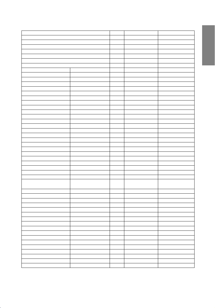
2.3 TECHNICAL SPECIFICATIONS
NOMINAL COOLING CAPACITY
TOTAL COOLING CAPACITY
SENSIBLE COOLING CAPACITY
LATENT COOLING CAPACITY
NO OF REFRIGERANT CIRCUITS
COMPRESSOR TYPE
EVAPORATOR FACE AREA
CONDENSER FACE AREA
INDOOR MOTOR TYPE
OUTDOOR MOTOR TYPE
BLOWER
FAN TYPE
CONNECTIONS CONDENSATE DRAIN SIZE
OVERALL DIMENSION-INDOOR (A)WIDTH
WEIGHT-INDOOR WEIGHT GROSS
OVERALL DIMENSION-OUTDOOR WIDTH
WEIGHT-OUTDOOR WEIGHT GROSS
DESCRIPTION
QTY
MAKE
MODEL
QTY
FIN DENSITY/ROWS
MATERIAL OF TUBE/FIN
QTY
FIN DENSITY/ROWS
MATERIAL OF TUBE/FIN
QUANTITY
POWER SUPPLY
SPEED
SHAFT DIAMETER
CLASS OF INSULATION
QUANTITY
POWER SUPPLY
SHAFT DIAMETER
CLASS OF INSULATION
FAN SPEED
TYPE
QTY
FAN MATERIAL
QTY
GAS OUTLET SIZE OD (nos)
LIQUID INLET SIZE,OD (nos)
(B)DEPTH
©HEIGHT
WEIGHT NET
DEPTH
HEIGHT
WEIGHT NET
UNITS LX-0356QC
TR 3.0
BTU/HR 18600 X 2
KCAL/HR 4650 X 2
KCAL/HR 4185 X 2
KCAL/HR 465 X 2
CFM 825 X 2AIRFLOW
NOS 2
NOS 2
Sq.M 0.223
NOS 2
FPI/No 14/2
Sq.M 0.272
NOS 2
FPI/No 14/3
NOS 2
RPM 960
mm 17
NOS 2
mm 12.7
RPM 880
NOS 2
NOS 2
mm 19
mm 12.7x2
mm 9.52x2
mm 665
mm 762
mm 938
KGS 90
KGS 85
mm 665
mm 550
mm 1080
KGS 110
KGS 105
Rotary
Hitachi
SH315CV-C7HU
Cu/Al-Precoat
Cu/Al-Precoat
INDUCTION MOTOR
230V-1PH-50Hz
B CLASS
INDUCTION MOTOR
230V-1PH-50Hz
B CLASS
CENTRIFUGAL,FORWARD
CURVE, DIDW
PROPELLER -AXIAL
Plastic
LX-0456QC
3.5
21000 X 2
5250 X 2
4725 X 2
525 X 2
960 X 2
2
Rotary
2
Hitachi
SH315CV-C7HU
0.223
2
14/3
Cu/Al-Precoat
0.272
2
14/3
Cu/Al-Precoat
INDUCTION MOTOR
2
230V-1PH-50Hz
1100
17
B CLASS
INDUCTION MOTOR
2
230V-1PH-50Hz
12.7
B CLASS
880
CENTRIFUGAL,FORWARD
CURVE, DIDW
2
PROPELLER -AXIAL
Plastic
2
19
12.7x2
9.52x2
665
762
938
92
87
665
550
1080
110
105
ENGLISH
7
3. INSTALLATION STANDARD
3.1 PRE-CHECK:
1. Remove the packing wooden base from indoor & outdoor unit.
2. Place the outdoor unit over mounting base (Concrete or I –beam) and
place antivibration pad and mount as per installation instructions.
3. Positioned the Indoor unit over Top of condensing unit and bolted indoor
with outdoor after fixing indoor to shelter cut-out portion.
4. Check there should not be any dents, dust in interconnecting piping.
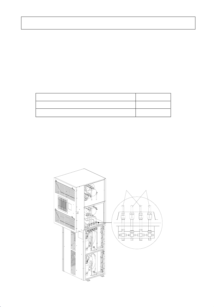
5. Prepare inter connection pipe to connect indoor unit with outdoor unit as
per following.
FLARED TYPE INTERCONNECTING PIPING SIZE X QTY.
SUCTION LINE INTERCONNECTING PIPING 1/2 inch X 2
LIQUID LINE INTER CONNECTING PIPING 3/8 inch X 2
6. Wrap Teflon tape in direction of thread to the connectors & service valve before
placing flared tubing.
7. Align the centre of the pipings (2 suctions & 2 liquids) and sufficiently tighten the
flare nut with fingers.
8. Finally tighten the flare nut with torque wrench until the wrench clicks (40~80kgf).
When tightening the flare nut with torque wrench, ensure the direction of
tightening follows the arrow of wrench.
Liquid
Interconnection
Suction
Interconnection
(A)
8
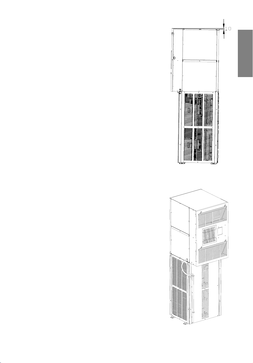
3.2. Levelling of Airconditioner
After placing the unit on Channel/concrete structure
maintain the levelling of unit towards rear side with
10mm slope so as to ensure free flow drainage.
Water seepage problem may happen due to improper
levelling of unit.
3.3. Shelter Cutout sealing
Angle flanges (4 nos) to be fixed with shelter wall after
installation. These flanges are to be fixed with shelter
wall after installation so as to prevent any leakage in
shelter. after fixing the flanges; apply silicon sealant
on edges of flanges to make complete leak free
cut-out. These are not the part of unit accessories.
ENGLISH
(B)
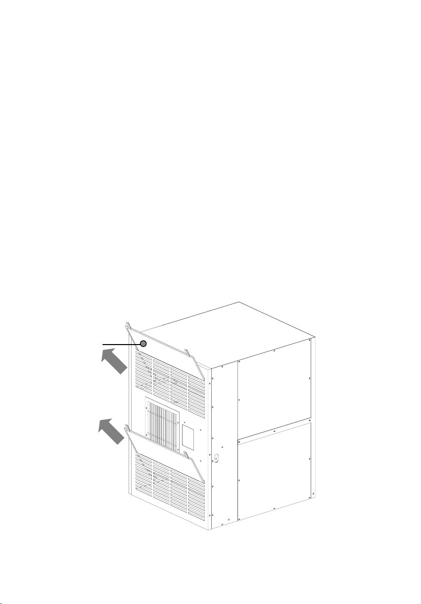
3.4. Condensate Drain pipe
1. Air conditioner is provided with one flexible drain
pipe, which shall be connected to metal Drain pipe
of unit & should be routed through gap between
shelter wall and condensing unit (see fig. C).
2. Do Not leave drain pipe open, your airconditioner
may suck condensate water and cause splitting of
water inside the shelter.
9
(C)
3.5. Air purging of inter connection & Indoor unit
The air which contains moisture remaining in the refrigeration cycle may cause
malfunction of compressor.
1. Confirm the both liquid valves& gas valves are set to closed position.
2. After connecting the piping, check the joints for gas leakage with gas leal
detector.
3. Remove the service port nut, and connect the gauge manifold and vacuum
pump to the service port by charge hose.
4. Vacuum the indoor unit & connecting pipes until the pressure in them lowers
to below 76 cmHg.
5. Remove the valve stem nuts. and fully open the stems of service valves with
hexagon wrench. & Tight the flare nuts of indoor & outdoor unit.
6. Purge the gas qty-80grams in each circuit to remove moist air contents.
7. Disconnect the charge hose and fit the nut to the service port.
(Tightening torque:1.8kg.m)
3.6. Filter Cleaning
The Airconditioner is equipped with fine air filter (2 nos.). The Air filter are at
front of unit shall be checked and cleaned every month or more often
if necessary.
Air-filter
10
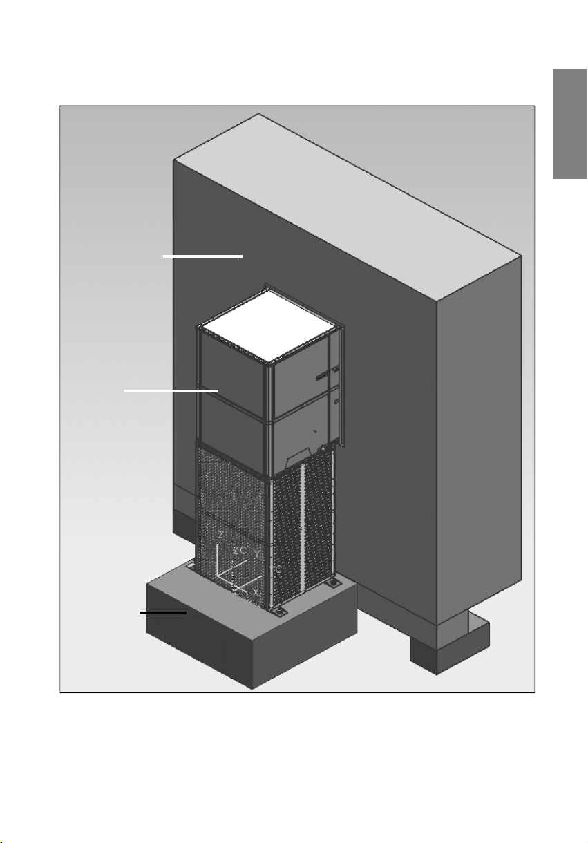
3.7. INSTALLATION DRAWING - CASE 1 :
CONCRETE BASEMOUNTING
SHELTER WALL
AC UNIT
ENGLISH
CONCRETE
BASE
11
 Loading...