

LG LW5224R-EP User Manual

OWNER'S MANUAL
Network Dome Camera
Please read this manual carefully before operating
your set and retain it for future reference.
MODEL
LW5224R
1110 (V1.0)
Cautions for Safe Operation
1
Cautions for Safe Operation
CAUTION: TO REDUCE THE RISK OF ELECTRIC SHOCK
DO NOT REMOVE COVER (OR BACK)
NO USER-SERVICEABLE PARTS INSIDE
REFER SERVICING TO QUALIFIED SERVICE PERSONNEL.
FCC WARNING: This equipment may generate or use radio
frequency energy. Changes or modifications to this equipment may
cause harmful interference unless the modifications are expressly
approved in the instruction manual. The user could lose the
authority to operate this equipment if an unauthorized change or
modification is made.
CAUTION
RISK OF ELECTRIC SHOCK
DO NOT OPEN
This lightning flash with arrowhead symbol
within an equilateral triangle is intended to
alert the user to the presence of uninsulated
dangerous voltage within the product’s
enclosure that may be of sufficient magnitude
to constitute a risk of electric shock to persons.
The exclamation point within an equilateral
triangle is intended to alert the user to
the presence of important operating and
maintenance (servicing) instructions in the
literature accompanying the product.
2
REGULATORY INFORMATION: FCC Part 15
This equipment has been tested and found to comply with the
limits for a Class A digital device, pursuant to Part 15 of the FCC
Rules. These limits are designed to provide reasonable protection
against harmful interference when the equipment is operated in a
commercial environment.
This equipment generates, uses, and can radiate radio frequency
energy and, if not installed and used in accordance with the
instruction manual, may cause harmful interference to radio
communications.
Operation of this equipment in a residential area is likely to cause
harmful interference in which case the user will be required to
correct the interference at his own expense.
• A suitable conduit entries, knock-outs or glands shall be provided in the cable entries of this product in the end user.
• Caution: Danger of explosion if battery is incorrectly replaced.
Replaced only with the same or equivalent type recommended
by the manufacturer. Dispose of used batteries according to the
manufacturer’s instructions.
• Holes in metal, through which insulated wires pass, shall have
smooth well rounded surfaces or shall be provided with brushings.
This Class A digital apparatus complies with Canadian ICES-003.
Cet appareil numérique de la classe A est conforme à la norme
NMB-003 du Canada.
Warning: Do not install this equipment in a confined space such as
a bookcase or similar unit.
Warning: Wiring methods shall be in accordance with the National
Electric Code, ANSI/NFPA 70.
Warning: This is a class A product. In a domestic environment this
product may cause radio interference in which case the user may be
required to take adequate measures.
Warning: To reduce a risk of fire or electric shock, do not expose this
product to rain or moisture.
Caution: This installation should be made by a qualified service
person and should conform to all local codes.
Caution: To avoid electrical shock, do not open the cabinet. Refer
servicing to qualified personnel only.
Caution: The apparatus shall not be exposed to water (dripping or
splashing) and no objects filled with liquids, such as vases, shall be
placed on the apparatus.
To disconnect power from mains, pull out the mains cord plug.
When installing the product, ensure that the plug is easily
accessible.
LG Electronics hereby declares that this/these
product(s) is/are in compliance with the essential
requirements and other relevant provisions of
Directive 2004/108/EC, 2006/95/EC and 2009/125/EC.
European representative :
LG Electronics Service Europe B.V.
Veluwezoom 15, 1327 AE Almere,
The Netherlands (Tel : +31-(0)36-547-8888)
Disposal of your old appliance
1. When this crossed-out wheeled bin symbol is
attached to a product it means the product is covered by the European Directive 2002/96/EC.
2. All electrical and electronic products should be
disposed of separately from the municipal waste
stream via designated collection facilities appointed
by the government or the local authorities.
3. The correct disposal of your old appliance will help
prevent potential negative consequences for the
environment and human health.
4. For more detailed information about disposal of
your old appliance, please contact your city office,
waste disposal service or the shop where you purchased the product.
EEE Compliance with Directive. (for Turkey only)
1
Cautions for Safe Operation
3

IMPORTANT SAFETY INSTRUCTIONS
1. Read these instructions.
2. Keep these instructions.
1
3. Heed all warnings.
Cautions for Safe Operation
4. Follow all instructions.
5. Do not use this apparatus near water.
6. Clean only with dry cloth.
7. Do not block any ventilation openings. Install in accordance with
the manufacturer’s instructions.
8. Do not install near any heat sources such as radiators, heat registers, stoves, or other apparatus (including amplifiers) that produce heat.
9. Do not defeat the safety purpose of the polarized or groundingtype plug. A polarized plug has two blades with one wider than
the other. A grounding type plug has two blades and a third
grounding prong. The wide blade or the third prong are provided for your safety. If the provided plug does not fit into your
outlet, consult an electrician for replacement of the obsolete
outlet.
10. Protect the power cord from being walked on or pinched particularly at plugs, convenience receptacles, and the point where
they exit from the apparatus.
11. Only use attachments/accessories specified by the manufacturer.
12. Use only with the cart, stand, tripod, bracket, or table specified
by the manufacturer, or sold with the apparatus. When a cart is
used, use caution when moving the cart/apparatus combination
to avoid injury from tip-over.
13. Unplug this apparatus during lightning storms or when unused
for long periods of time.
14. Refer all servicing to qualified service personnel. Servicing is
required when the apparatus has been damaged in any way,
such as power-supply cord or plug is damaged, liquid has been
spilled or objects have fallen into the apparatus, the apparatus
has been exposed to rain or moisture, does not operate normally, or has been dropped.
4

Handling of the unit
Be careful not to spill water or other liquids on the unit. Be cautious
not to get combustible or metallic material inside the body. If used
with foreign matter inside, the device is liable to fail or to get cause
of fire or electric shock.
• Remove dust or dirt on the surface of the lens with a blower.
• Use a dry soft cloth to clean the body. If it is very dirty, use a
cloth dampened with a small quantity of neutral detergent then
wipe dry.
• Avoid the use of volatile solvents such as thinners, alcohol, benzene and insecticides.
They may damage the surface finish and/or impair the operation
of the device.
Operating and storage location
Avoid viewing a very bright object (such as light fittings) during
an extended period. Avoid operating or storing the unit in the
following locations.
• Extremely hot or cold places (operating temperature from -10 °C
to 50 °C, however, we recommend that the unit be used within a
temperature range from 0 °C to 45 °C)
• Damp or dust place
• Places exposed to rain
• Places subject to strong vibration
• Close to generators of powerful electromagnetic radiation such
as radio or TV transmitters.
1
Cautions for Safe Operation
5

Contents
Introduction ................................................................................... 7
1
Part names and Functions .................................................................8
Connections ................................................................................. 10
2
3
Precautions ...........................................................................................10
Connection Overview ....................................................................... 10
Connecting Network.........................................................................11
Connecting Power Source .............................................................. 12
Connecting Alarm Device ...............................................................13
Connecting Microphone and Speaker Device .........................14
Mounting the camera ....................................................................... 15
4
Operation and settings ...............................................................22
Before using the system .................................................................. 22
5
Recommended PC Requirements ................................................ 22
Accessing the LG IP device.............................................................. 23
LG Smart Web Viewer Overview ................................................... 24
Conguring the LG Network camera .......................................... 25
OSD Menu Setup ................................................................................ 39
Reference .....................................................................................48
Troubleshooting .................................................................................48
Open source software notice .........................................................51
Specications.......................................................................................54
6

Introduction
The LG Network Dome Camera is designed to use on an Ethernet
network and must be assigned an IP address to make it accessible.
This manual contains instructions on how to install and manage the
LG Network Dome Camera in your networking environment. Some
knowledge of networking environments would be beneficial to the
reader.
Should you require any technical assistance, please contact
authorized service center.
Features
The LG Network Dome Camera offers the following functions:
• Dual H.264 Stream for single Video Input
• Multi-Codec (H.264, MJPEG) Streaming
• PoE(Power Over Ethernet) Support (802.3af)
• 3 Power (AC 24 V, DC 12 V, PoE) Support
• Audio Support (G.711, G.726 Full Duplex)
• Pre/Post Alarm Support
• High resolution and high sensitivity with a 6 mm Vertical Double
Interline CCD.
• Day & Night function
• 540 TV lines of horizontal resolution
Accessories
• Program CD
• Owner’s Manual
• Installation sticker
• Fixing screw
• External Video Output cable
2
Introduction
7
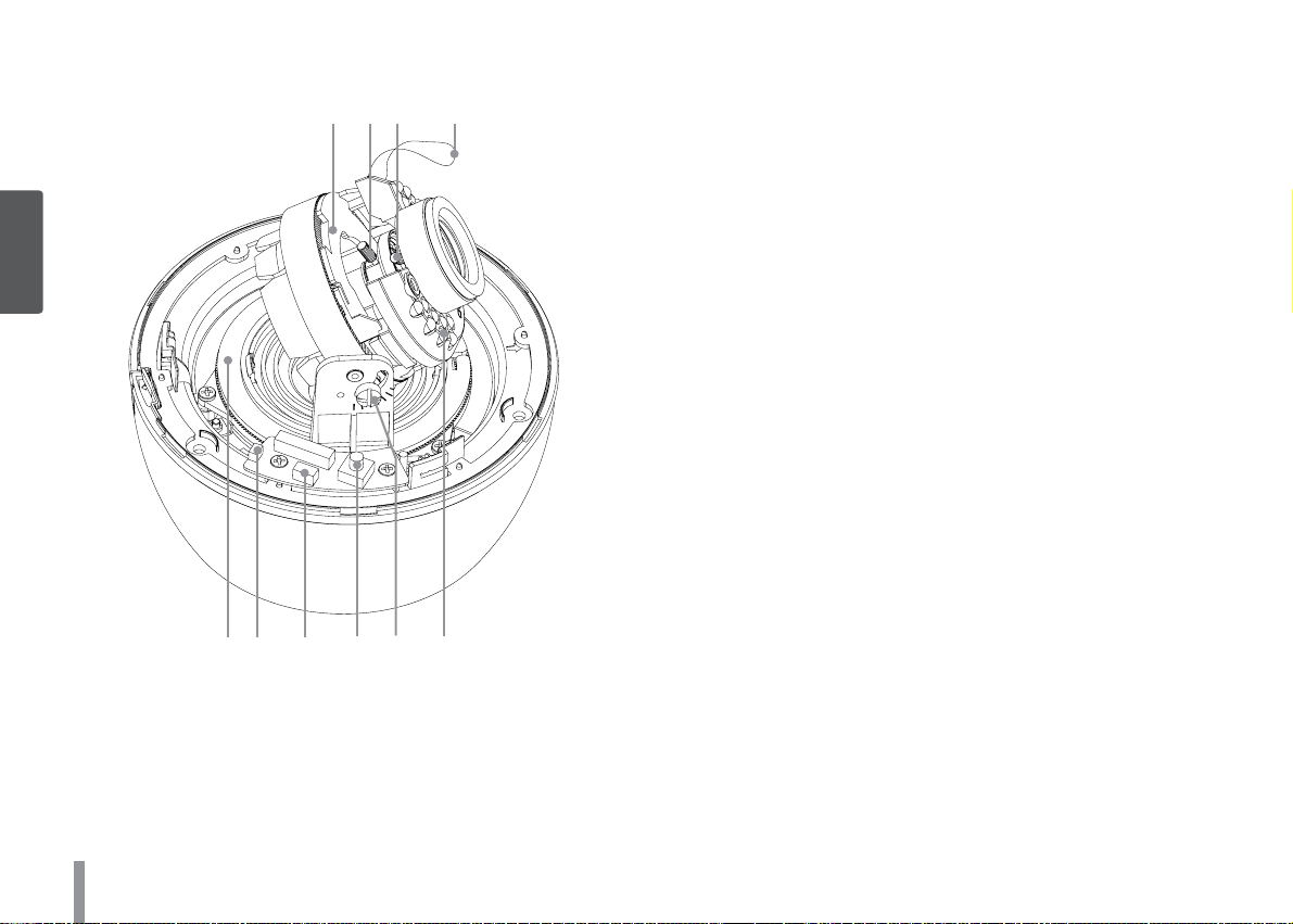
Part names and Functions
a b c d
2
Introduction
e f g h i j
a Azimuth angle assembly
Adjusting the azimuth angle to obtain a level image.
b Zoom lock lever
Fixes the zoom position after adjusting.
c Focus lock lever
Fixes the focus position after adjusting.
d Fall Prevention rubber band
Fixes the rubber band into the dome cover.
e Pan assembly
Use to adjust the panning position.
f Reset button
Push the button more than 3 seconds, this would restore the
factory default network related settings.
g Video Output connector
Supplies analog video signal (composite) to the connected
device. Connet the supplied External Video output cable to
this connector.
h OSD Setup menu control joystick
Use to set the OSD Setup menu.
i Tilting lock screw
Fixes the tilting position after adjusting.
j IR LED Lamps
8
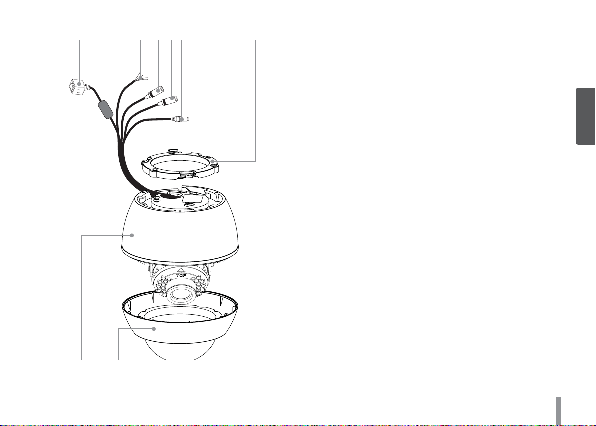
k l m n o p
k ETHERNET/POE Port
Connects to a PC or a network via a hub with a 10
BASE-T/100 BASE-TX cable attached RJ-45 connector.
Note:
Power over Ethernet (PoE) is a technology that integrates
power into a standard LAN infrastructure. It enables power
to be provided to the network device, such as a network
camera, using the same cable as that used for network
connection. It eliminates the need for power outlets at
the device locations and enables easier application of
uninterruptible power supplies (UPS).
l ALARM IN / ALARM IN RETURN
Provides physical interface for sensor.
ALARM OUT / ALARM OUT RETURN
Provides physical interface for Alarm/Relay.
m AUDIO OUT (Line Level Output)
Connect to an active speaker with a built-in amplifier.
n AUDIO IN (Line Level Input)
Input for a mono microphone, or a line-in mono signal.
o Power input jack
Connects to a DC 12 V or AC 24 V power supply using proper
cables.
p Camera mounting bracket
q Camera body
r Dome cover
2
Introduction
q r
9
Connections
Precautions
• Be sure to switch off the unit before installation and connection.
• The installation should be made by qualified service personnel or system installers.
• Do not expose the power and connection cables to moisture, which may cause damage to the unit.
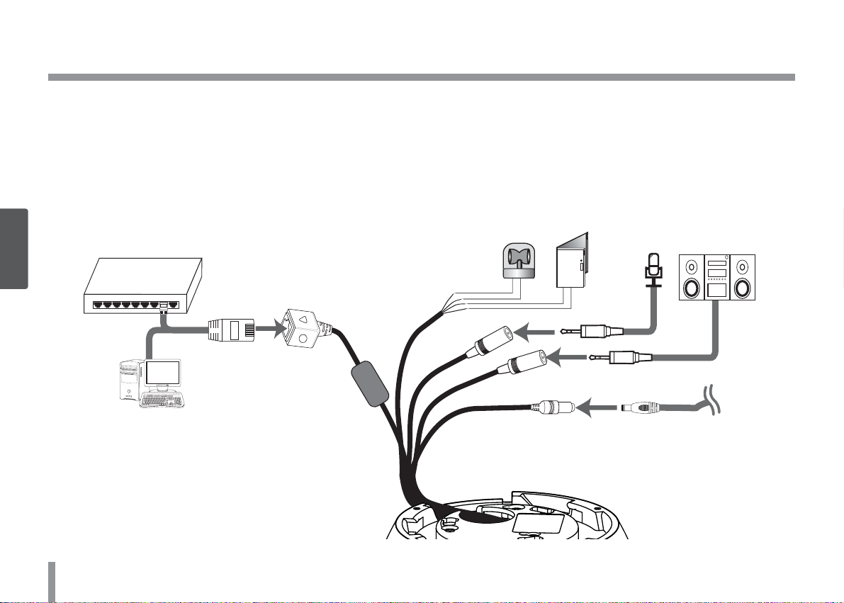
Connection Overview
PoE Device
3
Connections
PoE Device
(IEEE802.3af)
(IEEE802.3af )
10
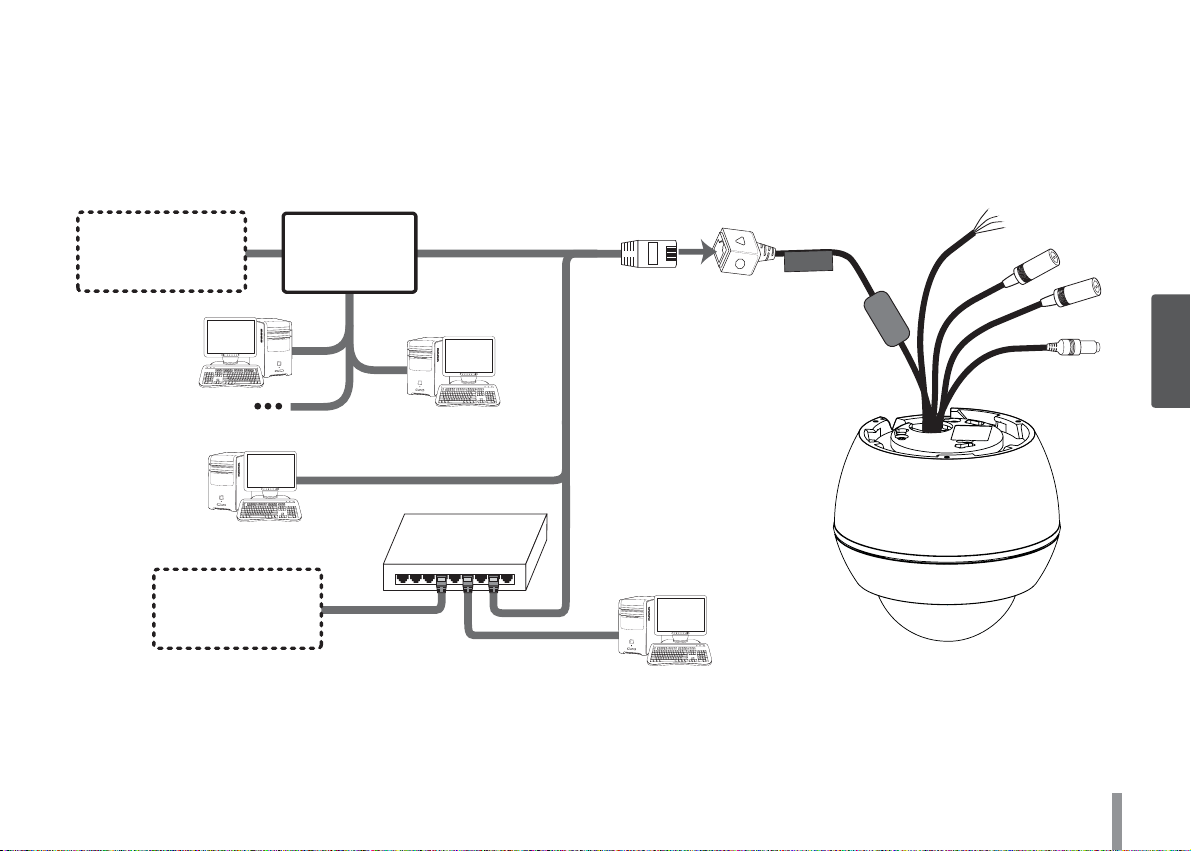
Connecting Network
You can control and monitor the system via network. With the remote control (monitoring), you can change the system configuration or
monitor the image via network. After the installation, check the network settings for the remote control and monitoring work.
Connect the IP camera to your network using a standard RJ-45 network cable as shown below.
Broadband
Broadband
Service
Service
Broadband
Broadband
Service
Service
Router
Router
PoE Device
PoE Device
(IEEE802.3af)
(IEEE802.3af )
ETHERNET
3
Connections
11
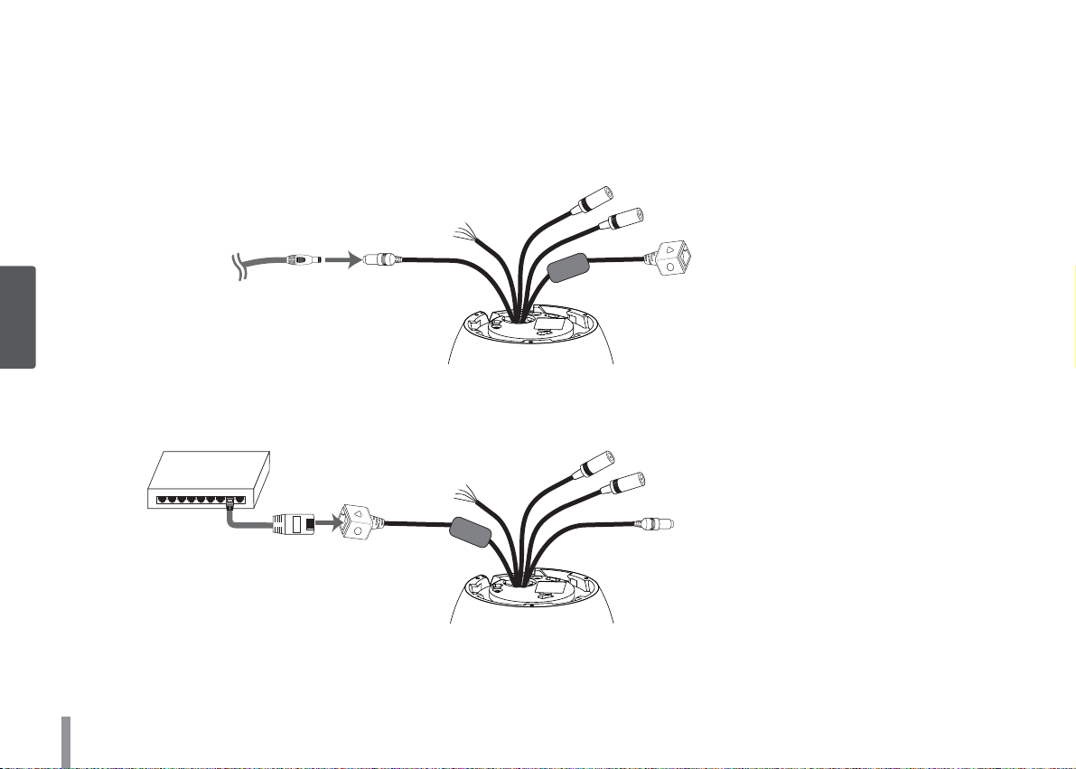
Connecting Power Source
Connect power, using one of the methods listed below:
To use the power adapter
Connect a DC 12 V / AC 24 V power source to the power input terminal as shown below.
(Connect to the DC 12 V / AC 24 V UL Listed, Class 2 Power Supply only on the unit. )
3
Connections
To use the PoE (Power over Ethernet) device
Connect the PoE cable to the LAN port on the unit.
You must use the “IEEE802.3af” standard PoE device.
PoE Device
PoE Device
(IEEE802.3af)
(IEEE802.3af )
Note:
If the camera doesn’t work properly after connecting PoE device, please check if the PoE device supplies enough power.
12
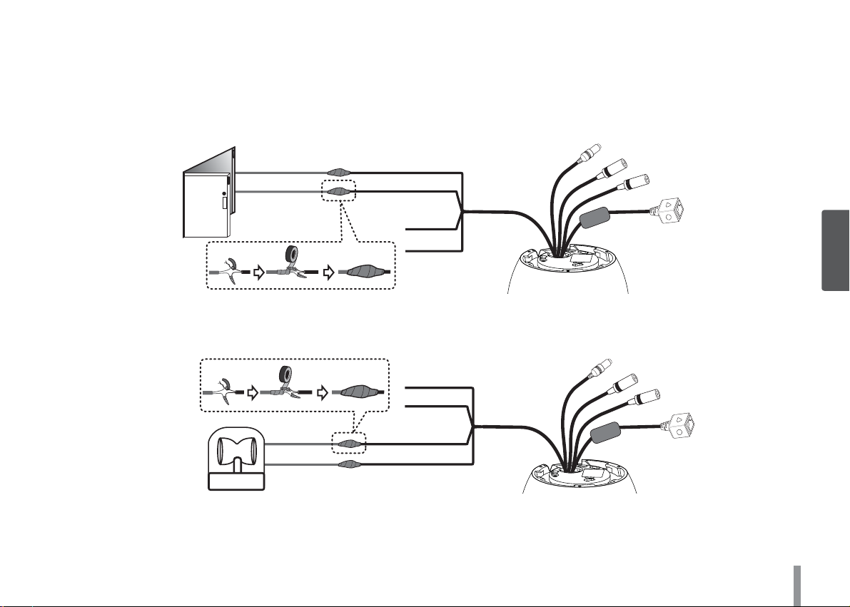
Connecting Alarm Device
Alarm terminals are used to connect the alarm (relay) devices such as sensors, door switches, etc.
ALARM IN / ALARM IN RETURN (Sensor Input)
Connect the sensor device to the sensor input terminal.
GREEN
Sensor Device
BLACK
ALARM OUT / ALARM OUT RETURN (Relay Output)
Connect the alarm (relay) device to the relay output terminal. Alarm signal is outputted at an event occurrence.
RED
Alarm (relay) Device
WHITE
Note:
The Photo MOS Relay is rated for 100 mA at 20 V DC or 100 mA at 28 V AC.
13
3
Connections
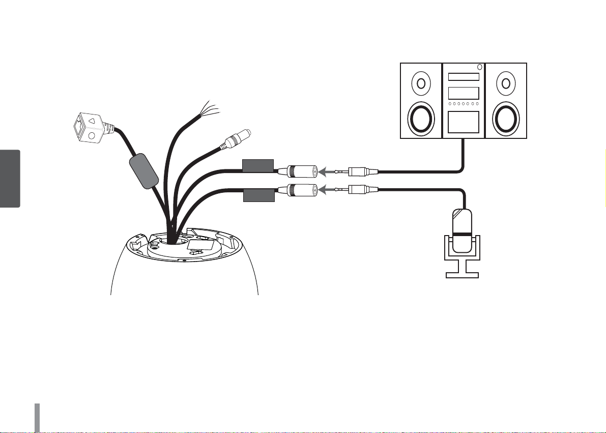
Connecting Microphone and Speaker Device
Optionally connect an active speaker and/or external microphone with a built-in amplifier.
AUDIO OUT
3
Connections
Note:
Keep the microphone away from the speaker to avoid howling.
14
AUDIO IN
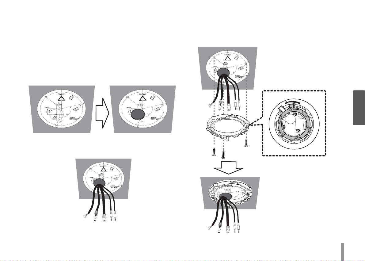
Mounting the camera
You can mount the camera on a ceiling or wall.
Surface mount
Follow the instructions below to mount the camera on a surface.
1. Use the installation guide template to check the mounting location. Face the front of the label toward the area of interest. Using
the template as a guide, make a hole through the ceiling.
2. Pass the connection cable through the inner side of the ceiling.
3. Install the camera bracket to the ceiling. Before you install the
camera bracket, turn the camera bracket counterclockwise while
pulling the locking knob to disassemble the camera bracket
from the camera body.
3
Connections
15
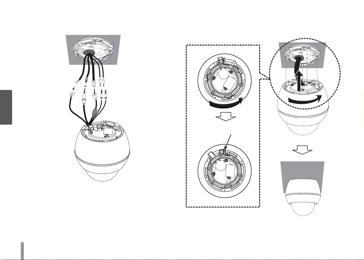
4. Connect the cables to the cable jacks of the camera body. 5. Turn the camera body clockwise while the locking knob is
pressed to fasten the camera body to the assembly bracket.
3
Connections
The locking knob
16
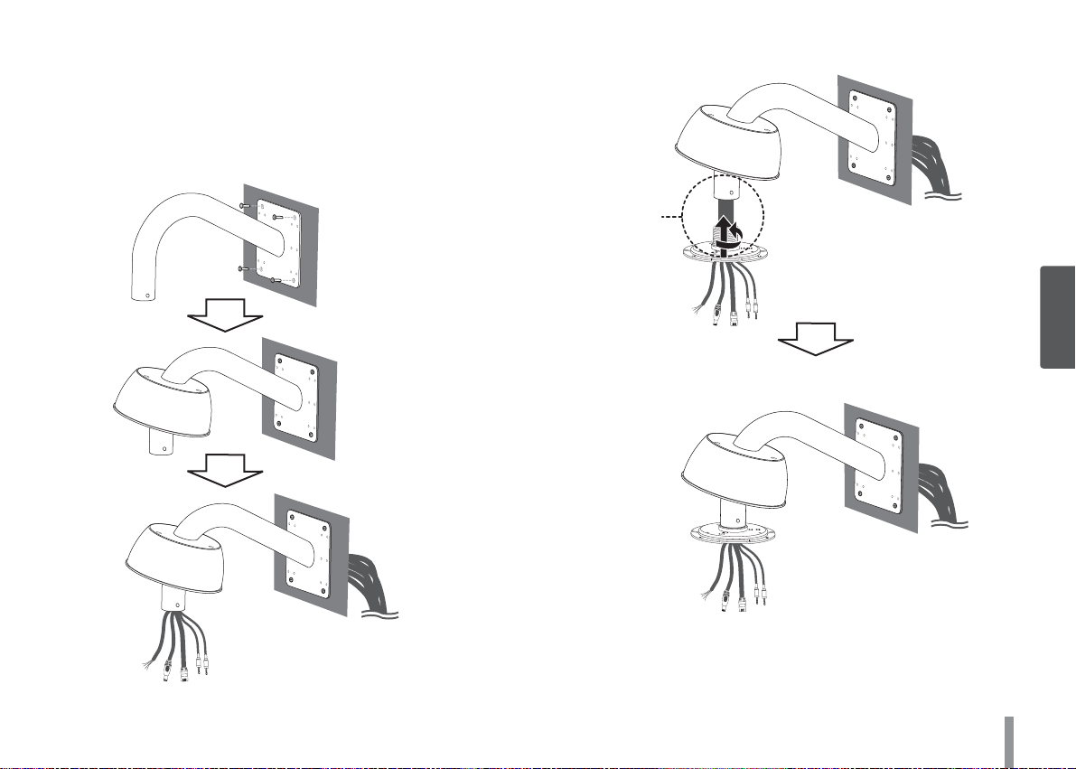
Wall mount (Optional)
“A”
Follow the instructions below to install the camera with a wall
mount.
1. Drill holes in the wall where you want to install the wall mount.
2. Install the wall mount as shown below.
3. Install the camera installation bracket as shown below.
Note:
Pipe threads should be clean and rust-free. Use a sealer such as
TM
tape and silicone sealer on the threads “A”.
Teflon
17
3
Connections
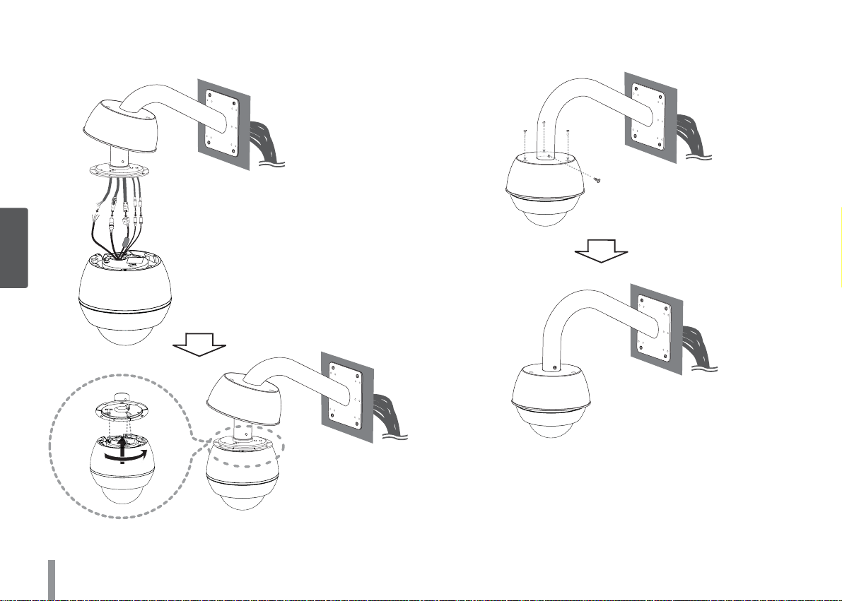
4. Connect the cables to the camera jack and attach the camera to
the installation bracket.
3
Connections
5. Attach the camera cover to the camera.
18
 Loading...