


LG Video Camera
Instruction Manual
Models : LVC-C382HM/HP
Before installing, operating or adjusting this
product, please read this instruction booklet
carefully and completely.
ENGLISH
CHINESE
RS-422/RS-485
COMMAND
LVC-C382HP_HA8CBL1_ENG 4/18/07 5:19 PM Page 1

2
This lightning flash with arrowhead symbol
within an equilateral triangle is intended to
alert the user to the presence of uninsulated dangerous voltage within the product’s
enclosure that may be of sufficient magnitude to constitute a risk of electric shock
to persons.
The exclamation point within an equilateral
triangle is intended to alert the user to the
presence of important operating and maintenance (servicing) instructions in the literature accompanying the product.
FCC WARNING:This equipment may generate or use
radio frequency energy. Changes or modifications to
this equipment may cause harmful interference unless
the modifications are expressly approved in the
instruction manual. The user could lose the authority
to operate this equipment if an unauthorized change
or modification is made.
REGULATORY INFORMATION: FCC Part 15
This equipment has been tested and found to comply
with the limits for a Class A digital device, pursuant to
Part 15 of the FCC Rules. These limits are designed
to provide reasonable protection against harmful interference when the equipment is operated in a commercial environment.
This equipment generates, uses, and can radiate
radio frequency energy and, if not installed and used
in accordance with the instruction manual, may cause
harmful interference to radio communications.
Operation of this equipment in a residential area is
likely to cause harmful interference in which case the
user will be required to correct the interference at his
own expense.
• A suitable conduit entries, knock-outs or glands
shall be provided in the cable entries of this product in the end user.
• Caution: Danger of explosion if battery is incorrectly replaced. Replaced only with the same or
equivalent type recommended by the manufacturer. Dispose of used batteries according to the
manufacturer’s instructions.
• Holes in metal, through which insulated wires
pass, shall have smooth well rounded surfaces or
shall be provided with brushings.
CAUTION: TO REDUCE THE RISK OF ELECTRIC SHOCK
DO NOT REMOVE COVER (OR BACK)
NO USER-SERVICEABLE PARTS INSIDE
REFER SERVICING TO QUALIFIED SERVICE PERSONNEL.
CAUTION
RISK OF ELECTRIC SHOCK
DO NOT OPEN
LVC-C382HP_HA8CBL1_ENG 4/18/07 5:19 PM Page 2
3
Warning: Do not install this equipment in a confined
space such as a bookcase or similar unit.
Warning: Wiring methods shall be in accordance with
the National Electric Code, ANSI/NFPA 70.
Warning: This is a class A product. In a domestic
environment this product may cause radio interference
in which case the user may be required to take adequate measures.
Warning: To reduce a risk of fire or electric shock, do
not expose this product to rain or moisture.
Caution: This installation should be made by a qualified service person and should conform to all local
codes.
Caution: To avoid electrical shock, do not open the
cabinet. Refer servicing to qualified personnel only.
Caution: The apparatus should not be exposed to
water (dripping or splashing) and no objects filled with
liquids, such as vases, should be placed on the apparatus.
This product is manufactured to comply
with the EEC DIRECTIVE 89/336/EEC,
93/68/EEC and 2006/95/EC.
Disposal of your old appliance
1. When this crossed-out wheeled bin
symbol is attached to a product it
means the product is covered by the
European Directive 2002/96/EC.
2. All electrical and electronic products
should be disposed of separately
from the municipal waste stream via
designated collection facilities
appointed by the government or the
local authorities.
3. The correct disposal of your old
appliance will help prevent potential
negative consequences for the environment and human health.
4. For more detailed information about
disposal of your old appliance,
please contact your city office, waste
disposal service or the shop where
you purchased the product.
ENGLISH
LVC-C382HP_HA8CBL1_ENG 4/18/07 5:19 PM Page 3

4
Important Safety Instructions
1. Read these instructions. - All these safety
and operating instructions should be read
before the product is operated.
2. Keep these instructions. - The safety, operating and use instructions should be retained for
future reference.
3. Heed all warnings. - All warnings on the product and in the operating instructions should be
adhered to.
4. Follow all instructions. - All operating and
use instructions should be followed.
5. Do not use this apparatus near water. - For
example: near a bath tub, wash bowl, kitchen
sink, laundry tub, in a wet basement; near a
swimming pool; etc.
6. Clean only with dry cloth. - Unplug this product from the wall outlet before cleaning. Do not
use liquid cleaners.
7. Do not block any ventilation openings.
Install in accordance with the manufacturer’s instructions. - Slots and openings in the
cabinet are provided for ventilation, to ensure
reliable operation of the product, and to protect
it from over- heating. The openings should
never be blocked by placing the product on a
bed, sofa, rug or other similar surface. This
product should not be placed in a built-in installation such as a bookcase or rack unless proper ventilation is provided and the manufacturer’s instructions have been adhered to.
8. Do not install near any heat sources such
as radiators, heat registers, stoves, or other
apparatus (including amplifiers) that produce heat.
LVC-C382HP_HA8CBL1_ENG 4/18/07 5:19 PM Page 4

5
9. Do not defeat the safety purpose of the
polarized or grounding-type plug. A polarized plug has two blades with one wider
than the other. A grounding type plug has
two blades and a third grounding prong.
The wide blade or the third prong are provided for your safety. If the provided plug
does not fit into your outlet, consult an
electrician for replacement of the obsolete
outlet.
10. Protect the power cord from being walked
on or pinched particularly at plugs, convenience receptacles, and the point where
they exit from the apparatus.
11. Only use attachments/accessories speci-
fied by the manufacturer.
12. Use only the cart, stand,
tripod, bracket, or table
specified by the manufacturer, or sold with
apparatus. When a cart is
used, use caution when
moving the cart/ apparatus combination to avoid injury from tipover.
13. Unplug this apparatus during lightning
storms or when unused for long periods
of time.
14. Refer all servicing to qualified service personnel. Servicing is required when the
apparatus has been damaged in any way,
such as power- supply cord or plug is
damaged, liquid has been spilled or
objects have fallen into the apparatus, the
apparatus has been exposed to rain or
moisture, does not operate normally, or
has been dropped.
ENGLISH
LVC-C382HP_HA8CBL1_ENG 4/18/07 5:19 PM Page 5

6
Contents and Features
Contents
Cautions for Safe Operation . . . . . . . . . . . . .7
Part Names and Functions . . . . . . . . . . . . .8-9
Control . . . . . . . . . . . . . . . . . . . . . . . . . .10-11
External Key (A/D IN) . . . . . . . . . . . . . . . . .12
Connections . . . . . . . . . . . . . . . . . . . . . . . .13
Line Lock Phase Adjustment . . . . . . . . . . . .14
Setup Menu . . . . . . . . . . . . . . . . . . . . . .15-16
Camera ID setting . . . . . . . . . . . . . . . . . . . .17
Focus settings . . . . . . . . . . . . . . . . . . . .18-20
AWB (Auto White Balance) Settings . . . .21-23
EXPOSURE 1 Settings . . . . . . . . . . . . . .24-26
EXPOSURE 2 Settings . . . . . . . . . . . . . .27-29
Special Settings . . . . . . . . . . . . . . . . . . .30-31
Motion Detection Setting . . . . . . . . . . . . . . .32
Function On-Screen Display Setting . . . . . .33
On Screen Display . . . . . . . . . . . . . . . . .34-36
Specifications . . . . . . . . . . . . . . . . . . . . .37-38
Features
The power zoom color video camera is
designed for use in monitoring system.
• High resolution and high sensitivity with a 1/4
inch CCD (Charge Coupled Device)
• High magnitude of zoom lens with
optical x27, Digital x270(MAX)
• Auto Focus
• Auto White balance
• Auto exposure with DC Iris control
• Day & Night function
• WDR(Wide Dynamic Range) is available
LVC-C382HP_HA8CBL1_ENG 4/18/07 5:19 PM Page 6

ENGLISH
7
Cautions for Safe Operation
Power Supply
This camera must always be operated a 24V
AC.
UL Listed, Class 2 Power Supply only.
Handling of the unit
Be careful not to spill water or other liquids on
the unit, or to get combustible or metallic material inside the body. If used with foreign matter
inside, the camera is liable to fail, or to be a
cause of fire or electric shock.
Operating and storage location
Avoid viewing a very bright object (such as light
fittings) for an extended period. Avoid operating
or storing the unit in the following locations.
• Extremely hot or cold places (operating temperature -10°C ~ 50°C).
• Damp or dust place.
• Where it is exposed to rain.
• Where it is subject to strong vibration.
• Close to generators of powerful electromagnetic radiation such as radio or TV transmitters.
Care of the unit
• Remove dust or dirt on the surface of the
lens with a blower.
• Use a dry soft cloth to clean the body. If it is
very dirty, use a cloth dampened with a small
quantity of neutral detergent, then wipe dry.
• Avoid the use of volatile solvents such as
thinners, alcohol, benzene, and insecticides.
They may damage the surface finish and/or
impair the operation of the camera.
LVC-C382HP_HA8CBL1_ENG 4/18/07 5:19 PM Page 7

8
Part Names and Functions
a Tripod adaptor
This adaptor can also be attached on the bottom
of the camera.
b Lens mount cap
c Power indicator
d Control buttons.
• T(TELE) button
When push, picture is telephoto.
• N(NEAR) button
In a manual situation, focus get near.
• M(MENU) button.
If you want to set up a diverse function, you
can push this button.
• W(WIDE) button
When push, picture is wide angle.
• F(FAR) button
In a manual situation, focus get far.
• H(HOT) button
Use to change the Day & Night mode.
ab
c
d
LVC-C382HP_HA8CBL1_ENG 4/18/07 5:19 PM Page 8

ENGLISH
9
Part Names and Functions
e CONTROL connector
Interface of camera control jack (10 Pin Din Jack
Type)
fVideo output (S-Video type)
Connect to the S-Video in connector of a monitor.
g Video output(BNC type)
Connect to the video in connector of a monitor.
h AC 24V terminal
Connect to an external power supply of AC 24V.
i LL/INT mode select switch
- LL : Line Lock Synchronization mode.
- INT : Internal Synchronization mode.
j Line Lock phase adjustment volume
e
f
g
h
ij
LVC-C382HP_HA8CBL1_ENG 4/18/07 5:19 PM Page 9
10
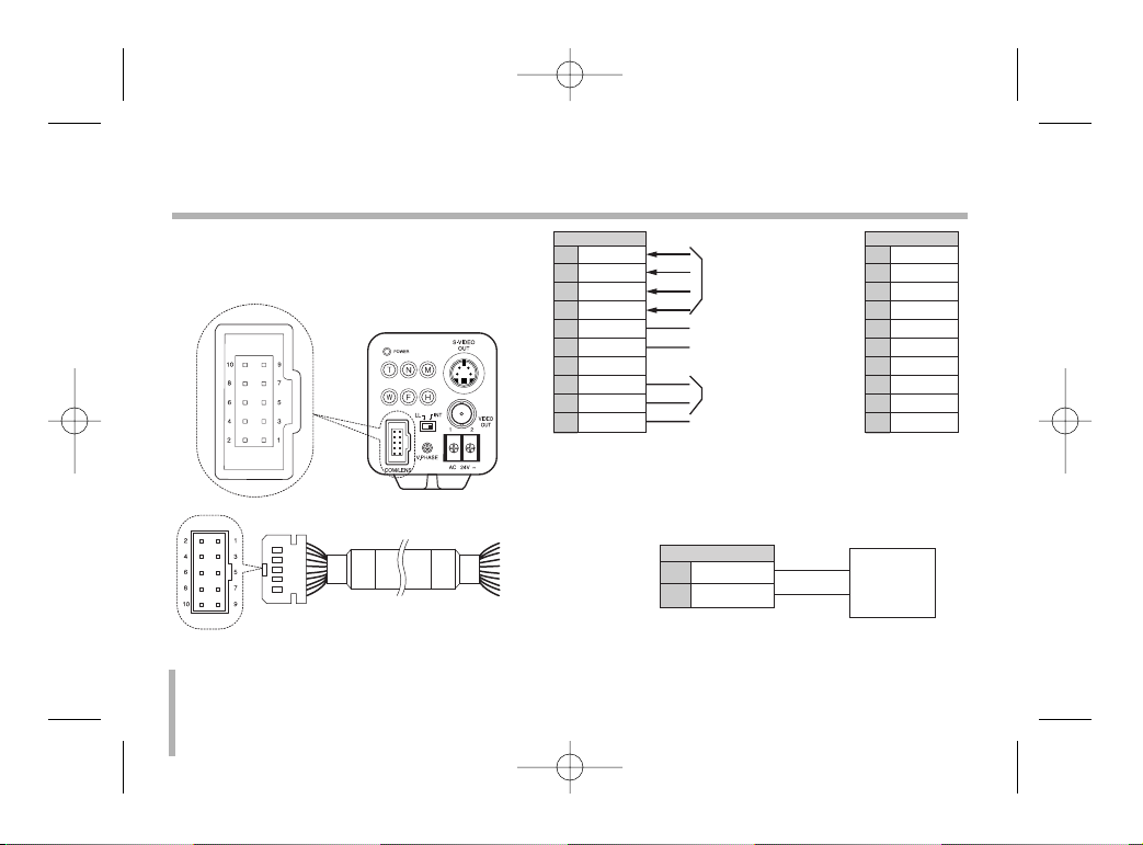
Control
You can control the PTZ and RS-485 by a pin
terminal on the back side of the camera.
* is the color of the cable. (If it is offered)
• RS-485 Connect
Zoom & Focus
DC Control
A/D Key 2 input
A/D Key 1 input
For RS-485 Control
Common GND
TR+
TR-
TR+
TR-
8
9
CN 312
RS-485 Controller
LVC-C382HP_HA8CBL1_ENG 4/18/07 5:19 PM Page 10
CN 312
ZOOM
1
COM
2
FOCUS
3
MENU/HOT
4
AD2
5
AD1
6
7
8
9
10
NC
TR+
TR-
GND
* Wire color
1
2
3
4
5
6
7
8
9
10
Green
Yellow
White
Yellow
Blue
Brown
Orange
Purple
Gray
Black
ENGLISH
11
Control
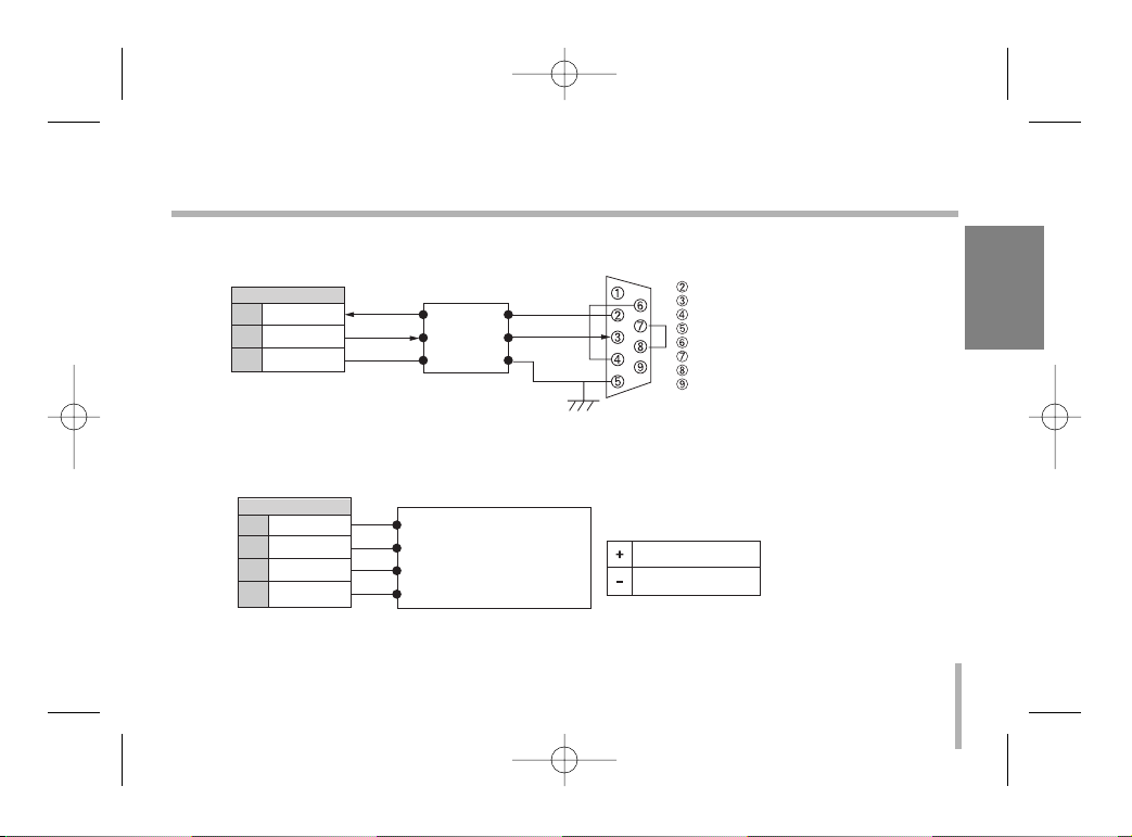
• RS-232C TTL Connect (Option)
• Zoom & Focus DC Control connect
TR+
TR-
GND
RxD
TxD
GND
RD
TD
DTR
SG
DSR
RTS
CTS
RI
RD
TD
GND
8
9
10
CN 312
RS-232C Drive
(RS-232C D-Sub 9 Connector)
ZOOM
COM
FOCUS
MENU/HOT
1
2
3
4
ZOOM ( + : Tele, - : Wide )
COMMON
FOCUS ( + : Near, - : Far )
MENU ( + : D&N, - : Menu)
Vcom + ( 6V~12V)
Vcom - (6V~12V)
CN 312
Voltage Range
Receiver Unit / Controller
LVC-C382HP_HA8CBL1_ENG 4/18/07 5:19 PM Page 11

External Key (A/D IN)
Schematic diagram of wired remote-control
12
No Function
AD1(1) Day&Night ON/OFF
AD1(2) Menu
AD1(3) Tele
AD1(4) Wide
AD1(5) Nega/Posi
AD1(6) Focus Near
AD1(7) Focus Far
AD1(8) Push Auto or A/M
No Function
AD2(1) Mirror
AD2(2) Initial Set
AD2(3) Shutter Speed
AD2(4) Backlight On/Off
AD2(5) Color On/Off
AD2(6) Digital Zoom On/Off
AD2(7) Digital Effect
AD2(8) OSD On/Off
LVC-C382HP_HA8CBL1_ENG 4/18/07 5:19 PM Page 12

Connections
Power connection
1. Remove the insulation on the power cable
as illustrated.
2. Attach the terminal tips.
3. Connect to the 24V AC UL Listed, Class 2
Power Supply only on the camera.
Connection the monitor
1. To VIDEO OUT
2. To Video input on the monitor
123
ENGLISH
13
12
LVC-C382HP_HA8CBL1_ENG 4/18/07 5:19 PM Page 13

14
Line Lock Phase Adjustment
12
3
When using a camera switcher to connect 2
cameras or more to one monitor, there may be
a vertical jump of the images when switched.
In such a case, refer to the below.
- The vertical sync phase can be manually
adjusted within the range approximately from
-90oC to +90oC.
- Switch the display on the monitor from camera1 to camera2.
Adjust the PHASE volume on camera2 until
the vertical jump of the image stops.
If more than two cameras are used, please
repeat this procedure for all the cameras.
- If you can’t adjust vertical sync. phase, please
exchange the polarity of input terminal.
1.
Camera switcher
2. Monitor
3. Vertical phase
LVC-C382HP_HA8CBL1_ENG 4/18/07 5:19 PM Page 14
ENGLISH
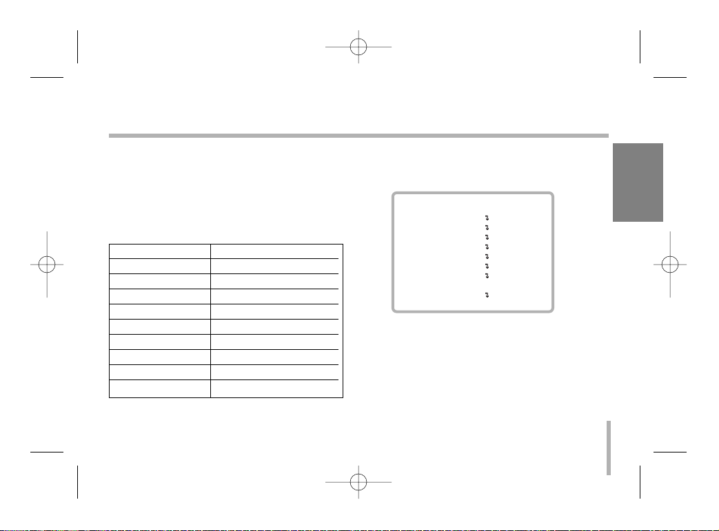
Setup Menu Overview
Setup menus are shown in the table left. You
can adapt the camera to your requirements by
setting up the respective items in these menus.
These menus are described on the following
pages for reference.
General Operation
1. Press [M] button on the rear of the camera.
MENU appears on the monitor.
2. Use [T] or [W] button to select an option
then press [N] or [F] button on the rear of
the camera.
Submenu appears on the monitor.
15
Setup Menu
Main Menu Page(s)
CAMERA ID 17
FOCUS SET 18-20
AWB SET 21-23
EXPOSURE 1 24-26
EXPOSURE 2 27-29
SPECIAL SET 30-31
MOTION DET 32
F.OSD DISP 33
INITIALIZE 16
MENU
CAMERA ID OFF
FOCUS SET
AWB SET
EXPOSURE 1
EXPOSURE 2
SPECIAL SET
MOTION DET
F.OSD DISP
INITIALIZE OFF
EXIT
LVC-C382HP_HA8CBL1_ENG 4/18/07 5:19 PM Page 15

16
Setup Menu
3. Use [T] or [W] button to select a submenu
option.
4. Use [N] or [F] button to select a value.
5. To close MENU, select [EXIT] option on the
MENU then press [N] or [F] button.
To return to MENU screen from submenu
Use [T] or [W] button to select [RETURN]
option then press [N] or [F] button on the sub
menu.
To reset your parameters to the factory
default settings
Use [T] or [W] button to select [INITIALIZE]
option then press [N] or [F] button.
Notes:
• [T] button : Use to move upper direction on
the menu screen.
• [W] button : Use to move lower direction on
the menu screen.
• [N] button : Use for increase the value of the
option.
• [F] button : Use for decrease the value of the
option.
LVC-C382HP_HA8CBL1_ENG 4/18/07 5:19 PM Page 16
ENGLISH
17
Camera ID setting
To connect a large number of camera , It can be assigned to
identification number to each camera for camera control easily.
(OFF, 0 - 255 : total numbers of ID are 256)
• It only can be set this function using ID commend.
To transfer ID Code of camera , In first byte at PC control.
Set the ID number of camera , and then the ID number display continuously.
MENU
CAMERA ID OFF
FOCUS SET
AWB SET
EXPOSURE 1
EXPOSURE 2
SPECIAL SET
MOTION DET
F.OSD DISP
INITIALIZE
EXIT
LVC-C382HP_HA8CBL1_ENG 4/18/07 5:19 PM Page 17

18
Focus settings
Focus Mode setting
The camera adjusts the focus automatically by sensing the center
of the picture.
Select [FOCUS MODE] option on the [FOCUS] menu, then select
the following mode.
• PUSH AUTO: Auto-focus is activated only when the Push Auto
key on the camera is pressed.
• MANUAL: Focus is activated only when the N (NEAR) or F
(FAR) keys on the camera is pressed.
• AUTO: Auto-focus is activated automatically.
Focus Distance setting
Selects the minimum shooting distance for the focus.
Select [FOCUS DIST] option on the [FOCUS] menu, then select a
Focus Distance value (1CM, 10CM, 50CM, 1M, 3M, 5M).
MENU
CAMERA ID OFF
FOCUS SET
AWB SET
EXPOSURE 1
EXPOSURE 2
SPECIAL SET
MOTION DET
F.OSD DISP
INITIALIZE
EXIT
FOCUS
FOCUS MODE PUSH AUTO
FOCUS DIST 1CM
ZOOM START x1
ZOOM END x270
ZOOM SPEED QUICK
ZOOM MODE AUTO
INITIALIZE OFF
RETURN
LVC-C382HP_HA8CBL1_ENG 4/18/07 5:19 PM Page 18

ENGLISH
19
Focus settings
Zoom Start setting
Selects a zoom start position.
Select [ZOOM START] option on the [FOCUS] menu, then select
a zoom’s start position (x1 - x26).
Zoom End setting
Selects a zoom end position.
Select [ZOOM END] option on the [FOCUS] menu,
then select a zoom’s end position from x270 to x(Zoom start+1).
Zoom Speed setting
Selects a zoom speed.
Select [ZOOM SPEED] option on the [FOCUS] menu, then select
a zoom speed (SLOW, MIDDLE, QUICK).
MENU
CAMERA ID OFF
FOCUS SET
AWB SET
EXPOSURE 1
EXPOSURE 2
SPECIAL SET
MOTION DET
F.OSD DISP
INITIALIZE
EXIT
FOCUS
FOCUS MODE PUSH AUTO
FOCUS DIST 1CM
ZOOM START x1
ZOOM END x270
ZOOM SPEED QUICK
ZOOM MODE AUTO
INITIALIZE OFF
RETURN
LVC-C382HP_HA8CBL1_ENG 4/18/07 5:19 PM Page 19

20
Focus settings
Zoom Tracking Mode setting
Selects a zoom tracking mode. Zoom tracking means focused
zooming state.
Select [ZOOM MODE] option on the [FOCUS] menu, then select
a zoom tracking mode (AUTO, MANUAL).
MENU
CAMERA ID OFF
FOCUS SET
AWB SET
EXPOSURE 1
EXPOSURE 2
SPECIAL SET
MOTION DET
F.OSD DISP
INITIALIZE
EXIT
FOCUS
FOCUS MODE PUSH AUTO
FOCUS DIST 1CM
ZOOM START x1
ZOOM END x270
ZOOM SPEED QUICK
ZOOM MODE AUTO
INITIALIZE OFF
RETURN
LVC-C382HP_HA8CBL1_ENG 4/18/07 5:19 PM Page 20

21
AWB (Auto White Balance) Settings
Setting the AWB (Auto White Balance) Mode
You can select one of four modes for white balance adjustment.
Select [AWB MODE] option on the [AWB] menu, then select the
following mode.
• AUTO (Auto-Tracing White Balance): In this mode, the color
temperature is monitored continuously and thereby white balance is automatically set. The color temperature range for the
proper white balance is approximately 2800 - 8000 ºK. Proper
white balance may not be obtained under the following conditions:
1) The color temperature is out of the 2800 - 8000 ºK range.
2) When the scene contains mostly high color temperature
objects, such as a blue sky or sunset.
3) When the scene is dim.
• SPECIAL : Under the special WB condition(Differ from curve of
the control color temperature ), Adjust Red and Blue to perform
a desired Auto White Balance.
• INDOOR : The color temperature range for the proper white
balance is approximately 3200K.
ENGLISH
MENU
CAMERA ID OFF
FOCUS SET
AWB SET
EXPOSURE 1
EXPOSURE 2
SPECIAL SET
MOTION DET
F.OSD DISP
INITIALIZE
EXIT
AWB
AWB MODE AUTO
RED ADJUST NOT USE
BLUE ADJUST NOT USE
PUSH AUTO NOT USE
INITIALIZE OFF
RETURN
LVC-C382HP_HA8CBL1_ENG 4/18/07 5:19 PM Page 21
22
AWB (Auto White Balance) Settings
• OUTDOOR: The color temperature range for the proper white
balance is approximately 5100K.
• MANUAL : You can set the white balance options manually.
• PUSH AUTO: The White Balance will be adjusted automatically.
RED ADJUST Setting
This function is available for SPECIAL, PUSH AUTO, MANUAL
AWB mode. Obtains the optimum amount of red gain.
Adjust the level is as shown below.
• SPECIAL : from -30 to 30.
• PUSH AUTO : from -128 to +127.
• MANUAL : from 0 to 255.
MENU
CAMERA ID OFF
FOCUS SET
AWB SET
EXPOSURE 1
EXPOSURE 2
SPECIAL SET
MOTION DET
F.OSD DISP
INITIALIZE
EXIT
AWB
AWB MODE AUTO
RED ADJUST NOT USE
BLUE ADJUST NOT USE
PUSH AUTO NOT USE
INITIALIZE OFF
RETURN
LVC-C382HP_HA8CBL1_ENG 4/18/07 5:19 PM Page 22

23
AWB (Auto White Balance) Settings
BLUE ADJUST Setting
This function is available for SPECIAL, PUSH AUTO, MANUAL
AWB mode. Obtains the optimum amount of blue gain.
Adjust the level is as shown below.
• SPECIAL : from -30 to 30.
• PUSH AUTO : from -128 to +127.
• MANUAL : from 0 to 255.
PUSH AUTO Setting
This function is available for PUSH AUTO AWB mode. If the
PUSH AUTO option is set to ON, the AWB will be activated automatically.
ENGLISH
MENU
CAMERA ID OFF
FOCUS SET
AWB SET
EXPOSURE 1
EXPOSURE 2
SPECIAL SET
MOTION DET
F.OSD DISP
INITIALIZE
EXIT
AWB
AWB MODE AUTO
RED ADJUST NOT USE
BLUE ADJUST NOT USE
PUSH AUTO NOT USE
INITIALIZE OFF
RETURN
LVC-C382HP_HA8CBL1_ENG 4/18/07 5:19 PM Page 23

24
EXPOSURE 1 Settings
AE Mode setting
Selects an Automatic Exposure mode.
Select [AE MODE] option on the [EXPOSURE 1] menu, then
select an Automatic Exposure mode.
• AUTO : Use to compensate the exposure automatically.
• IRIS MAN : Use to change the value of Lens’ Iris (IRIS of lens
is fixed manually, and the action of exposure compensation
depend on its of AGC).
• AGC MAN : Use to change the value of AGC manually.
• MANUAL : Use to change the Shutter Speed control. In this
time, AE mode act automatically (10 steps control is available).
Iris Adjust setting
Selects a iris’ exposure value. This option is available only when
[AE MODE] is set to [IRIS MAN] or [MANUAL].
Select [IRIS ADJUST] option on the [EXPOSURE 1] menu, then
select a value. (0 - 255)
MENU
CAMERA ID OFF
FOCUS SET
AWB SET
EXPOSURE 1
EXPOSURE 2
SPECIAL SET
MOTION DET
F.OSD DISP
INITIALIZE
EXIT
EXPOSURE 1
AE MODE AUTO
IRIS ADJUST AUTO
AGC ADJUST AUTO
BRIGHTNESS 42
FLICKERLESS OFF
SHUTTER NORMAL
INITIALIZE OFF
RETURN
LVC-C382HP_HA8CBL1_ENG 4/18/07 5:19 PM Page 24
25
EXPOSURE 1 Settings
AGC(Automatic Gain Control) ADJUST setting
If the images are too dark, change the maximum [AGC] value to
make the images lighter. This option is available when [AE
MODE] is set to [AGC MAN] or [MANUAL].
Select [AGC ADJUST] option on the [EXPOSURE 1] menu, then
select a value (0 - 255, 8 steps).
Brightness Setting
The lens iris is fixed at the value that you have set regardless of
the brightness of an object. This option is available when [AE
MODE] is set to [AUTO], [IRIS MAN] or [AGC MAN]. Select
[BRIGHTNESS] option on the [EXPOSURE 1] menu, then select
a value (0 - 99).
Flickerless Setting
Use for removing the flicker of picture.
Select [FLICKERLESS] option on the [EXPOSURE 1] menu, then
select an option (ON or OFF). Set to [ON] to remove the flicker.
ENGLISH
MENU
CAMERA ID OFF
FOCUS SET
AWB SET
EXPOSURE 1
EXPOSURE 2
SPECIAL SET
MOTION DET
F.OSD DISP
INITIALIZE
EXIT
EXPOSURE 1
AE MODE AUTO
IRIS ADJUST AUTO
AGC ADJUST AUTO
BRIGHTNESS 42
FLICKERLESS OFF
SHUTTER NORMAL
INITIALIZE OFF
RETURN
LVC-C382HP_HA8CBL1_ENG 4/18/07 5:19 PM Page 25

26
EXPOSURE 1 Settings
Shutter Speed Setting
You can select a shutter speed among NORMAL, 1/125, 1/250,
1/500, 1/1000, 1/2000, 1/4000 or 1/10000 seconds.
This option is available only when [FLICKERLESS] option is set
to [OFF].
Select [SHUTTER] option on the [EXPOSURE 1] menu, then
select a shutter speed.
MENU
CAMERA ID OFF
FOCUS SET
AWB SET
EXPOSURE 1
EXPOSURE 2
SPECIAL SET
MOTION DET
F.OSD DISP
INITIALIZE
EXIT
EXPOSURE 1
AE MODE AUTO
IRIS ADJUST AUTO
AGC ADJUST AUTO
BRIGHTNESS 42
FLICKERLESS OFF
SHUTTER NORMAL
INITIALIZE OFF
RETURN
LVC-C382HP_HA8CBL1_ENG 4/18/07 5:19 PM Page 26

27
EXPOSURE 2 Settings
E.SENSITIVE Setting
This model does not support the DSS function. E.SENSITIVE
function is always “NOT USED”.
DAY&NIGHT Setting
It is a function of a color camera to delete the filter with the IR
Cut function in an illumination below the standard value so that it
has a better sensitivity.
Select [DAY&NIGHT] option on the [EXPOSURE 2] menu, then
select one of the following mode.
• AUTO: The DAY&NIGHT function is changed to day and night
mode automatically.
• NIGHT: Black-and-white mode enabled.
• DAY: Color mode enabled.
ENGLISH
MENU
CAMERA ID OFF
FOCUS SET
AWB SET
EXPOSURE 1
EXPOSURE 2
SPECIAL SET
MOTION DET
F.OSD DISP
INITIALIZE
EXIT
EXPOSURE 2
E.SENSITIVE NOT USED
DAY&NIGHT AUTO
BACKLIGHT OFF
BLC LEVEL 32
WDR CONTROL OFF
WDR LEVEL 5
INITIALIZE OFF
RETURN
LVC-C382HP_HA8CBL1_ENG 4/18/07 5:19 PM Page 27
28
EXPOSURE 2 Settings
Backlight Setting
Improves an image that is darkened because of backlighting.
Select [BACKLIGHT] option on the [EXPOSURE 2] menu, then
select a value.
• OFF: The back light compensation is not used.
• ON: The back light compensation is used.
• AUTO (Auto back light compensation): If you use an ordinary
camera when there is an intense and concentrated illumination
behind an object, the back light will shade the image on the
monitor screen. The Backlight function prevents such a back
light effect to secure a clear image under all illumination environments.
MENU
CAMERA ID OFF
FOCUS SET
AWB SET
EXPOSURE 1
EXPOSURE 2
SPECIAL SET
MOTION DET
F.OSD DISP
INITIALIZE
EXIT
EXPOSURE 2
E.SENSITIVE NOT USED
DAY&NIGHT AUTO
BACKLIGHT OFF
BLC LEVEL 32
WDR CONTROL OFF
WDR LEVEL 5
INITIALIZE OFF
RETURN
LVC-C382HP_HA8CBL1_ENG 4/18/07 5:19 PM Page 28

29
EXPOSURE 2 Settings
BLC (Back Light Compensation) Level Setting
Selects a level for the BLC (back light compensation).
Select [BLC LEVEL] option on the [EXPOSURE 2] menu, then
select a desired level (0-80).
WDR (Wide Dynamic Range) Control setting
Select [WDR CONTROL] option on the [EXPOSURE 2] menu,
then select one of the following mode.
• AUTO : The camera selects WDR mode automatically.
• ON: WDR control mode enabled.
• OFF: The WDR control is not used.
WDR (Wide Dynamic Range) Level setting
Selects a level for the WDR (Wide Dynamic Range).
Select [WDR LEVEL] option on the [EXPOSURE 2] menu, then
select a desired level (0-255).
ENGLISH
MENU
CAMERA ID OFF
FOCUS SET
AWB SET
EXPOSURE 1
EXPOSURE 2
SPECIAL SET
MOTION DET
F.OSD DISP
INITIALIZE
EXIT
EXPOSURE 2
E.SENSITIVE NOT USED
DAY&NIGHT AUTO
BACKLIGHT OFF
BLC LEVEL 32
WDR CONTROL OFF
WDR LEVEL 5
INITIALIZE OFF
RETURN
LVC-C382HP_HA8CBL1_ENG 4/18/07 5:19 PM Page 29
30
Special Settings
User Title Setting
You can name the camera independently.
1. Move the cursor to [USER TITLE] on the [SPECIAL] menu.
Arrow mark appears.
2. Move the arrow mark to the desired position then select a character.
• [N] : Move to right position.
• [F] : Move to left position.
• [T] or [W] : Selects a character on the arrow position.
3. Repeat step 2 to set the remain characters.
Sharpness Setting
Sharpens the image outline.
Select [SHARPNESS] option on the [SPECIAL] menu, then select
a value. (0 - 15)
MIRROR Setting
Select [MIRROR] option on the [SPECIAL] menu, then select an
option (ON or OFF).
MENU
CAMERA ID OFF
FOCUS SET
AWB SET
EXPOSURE 1
EXPOSURE 2
SPECIAL SET
MOTION DET
F.OSD DISP
INITIALIZE
EXIT
SPECIAL
USER TITLE
ssssssssssssssssssss
SHARPNESS 10
MIRROR OFF
COLOR ON
NEGATIVE OFF
WIDE BURST OFF
ENG/CHI ENGLISH
INITIALIZE OFF
RETURN
LVC-C382HP_HA8CBL1_ENG 4/18/07 5:19 PM Page 30

31
Special Settings
Color Setting
You can switch the displayed picture to grayscale or color.
Select [COLOR] option on the [SPECIAL] menu, then select an
option (ON or OFF). Set to [ON] to display the picture with color.
Set to [OFF] to display the picture with grayscale.
Negative Setting
You can use the negative effect.
Select [NEGATIVE] option on the [SPECIAL] menu, then select
an option (ON or OFF).
WIDE BURST Setting
This mode is to change color burst width for long distance application. Select [WIDE BURST] option on the [SPECIAL] menu,
then select an option (ON or OFF).
ENG/CHI Setting (Optional)
Select a language for setup menu and information display.
ENGLISH
MENU
CAMERA ID OFF
FOCUS SET
AWB SET
EXPOSURE 1
EXPOSURE 2
SPECIAL SET
MOTION DET
F.OSD DISP
INITIALIZE
EXIT
SPECIAL
USER TITLE
ssssssssssssssssssss
SHARPNESS 10
MIRROR OFF
COLOR ON
NEGATIVE OFF
WIDE BURST OFF
ENG/CHI ENGLISH
INITIALIZE OFF
RETURN
LVC-C382HP_HA8CBL1_ENG 4/18/07 5:19 PM Page 31

32
Motion Detection Setting
Motion Detection Setting
The motion detection detects the moving objects in the scene by
monitoring changes in brightness level.
Select [DETECTION] option on the [MOTION] menu, then select
an option (ON or OFF).
Detection Level Setting
You can select the level of sensitivity for motion detection.
Select [DET LEVEL] option on the [MOTION] menu, then select a
desired level (0-21).
MENU
CAMERA ID OFF
FOCUS SET
AWB SET
EXPOSURE 1
EXPOSURE 2
SPECIAL SET
MOTION DET
F.OSD DISP
INITIALIZE
EXIT
MOTION
DETECTION ON
DET LEVEL 10
INITIALIZE OFF
RETURN
LVC-C382HP_HA8CBL1_ENG 4/18/07 5:19 PM Page 32

33
Function On-Screen Display Setting
You can set the Function On-Screen Display options using the [F.
OSD] menu.
The Function On-Screen Display of this camera can be turned on
or off.
Select an option (DISP ON or OFF).
• DISP ON: Displays the Function On-Screen Display on the
screen.
• OFF: The Function On-Screen Display dose not appear on the
screen.
ENGLISH
MENU
CAMERA ID OFF
FOCUS SET
AWB SET
EXPOSURE 1
EXPOSURE 2
SPECIAL SET
MOTION DET
F.OSD DISP
INITIALIZE
EXIT
F.OSD
FUNCTION DISP ON
MOTION DET DISP ON
CAMERA ID DISP ON
ZOOM MAG DISP ON
USER TITLE DISP ON
INIT TITLE DISP ON
INITIALIZE OFF
RETURN
LVC-C382HP_HA8CBL1_ENG 4/18/07 5:19 PM Page 33

34
On Screen Display
Some of these functions will be displayed every time the camera
is operated and then disappeared after 5 seconds.
FUNCTION OSD Format Description
1. Focus Mode Non display Auto Mode
☞ Manual / push Auto Mode
2. Back Light Non display Back Light OFF
“BL”display BLC ON / Auto BLC Mode
3. Shutter Non display Normal Shutter ( PAL: 1/50)
Speed “Ff”display Flickerless Mode
1/125 8 variable steps
...
1/10000
LVC-C382HP_HA8CBL1_ENG 4/18/07 5:19 PM Page 34
12 3 4
BL 1/10000
MOTION DETECTED
STAND-BY
5
876

ENGLISH
35
On Screen Display
FUNCTION OSD Format Description
4. WBC MODE AWB White Balance AUTO
Special Auto White Balance ;
SWB Adjustment Mode according to change of external illuminant.
RED ADJUST and BLUE ADJUST ( 0 ~ 255 ) are available.
After changing R/B value, The mainternance mode is “ AUTO”.
WB Preset for INDOOR
WB Preset for OUTDOOR
M Manual WB Adjustment ;
W In manual mode the HUE control is available ( 0 ~ 99 ).
Push Auto White Balance ;
PWB Turn this mode ON , the white trace automatically turn this
mode OFF, Preserve the white of final auto tracing action
(Manual ).
LVC-C382HP_HA8CBL1_ENG 4/18/07 5:19 PM Page 35

36
On Screen Display
FUNCTION OSD Format Description
5. Motion MOTION Motion DET ON mode
Detect DETECTED
6. CAMERA ID According to write the identification number to each camera ,
Multi-point control is available (PC Control 000 ~ 255 ).
7. ZOOM DX 270 Digital Zoom mode
DISPLAY X 27 Optical l Zoom mode
8. STAND-BY STAND-BY Indicate the camera stand-by during the camera’s power
MODE turning ON .
LVC-C382HP_HA8CBL1_ENG 4/18/07 5:19 PM Page 36

ENGLISH
37
Specifications
Model LVC-C382HM LVC-C382HP
Signal System NTSC ( High Resolution ) PAL ( High Resolution )
Pick- Up Device 1 / 4'' Super HAD CCD
Total Pixcels No. 811 (H) X 508 (V) 410K 795 (H) X 596 (V) 470K
Effective Pixcels No. 768 (H) X 494 (V) 380K 752 (H) X 582 (V) 440K
Scanning System 2 : 1 Interlace
Scanning Frequency ( H ) 15.734 KHz 15.625 KHz
Scanning Frequency ( V ) 59.94 Hz 50 Hz
S/N Ratio More Than 48 dB
Horizontal Resolution More Than 480 TV Lines More Than 480 TV Lines
LENS X 27 Zoom ( F 1.5 (W) ,F 3.8(T) f = 3.25 ~88.0 mm )
Minimum Shooting Distance 0.01m ( WIDE ) , 1.2m (TELE )
Minimum Illumination 1 Lux (30 IRE )
Sync System Internal/External (L.L.)
LVC-C382HP_HA8CBL1_ENG 4/18/07 5:19 PM Page 37

Model LVC-C382HM LVC-C382HP
Video Output 1Vp-p Composite Output 75 Ω Terminated, S-Video Output
Operation Temperature -10˚C ~ 50˚C , 0 % RH ~ 60 % RH
Storage Temperature -20˚C ~ 60˚C , 0 % RH ~ 85 % RH
Supplied Voltage AC 24 V ± 10 %
Power Consumption Max 6 W
Dimensions ( W x H x D ) 57 x 68.5 x 143
Net Weight (Approx.) 545g
38
Specifications
LVC-C382HP_HA8CBL1_ENG 4/18/07 5:19 PM Page 38

摄像机
使用手册
型号 : LVC-C382HM/HP
在您安装、操作和调整此产品前,请仔细阅读本
手册。
CHINESE
RS-422/RS-485
COMMAND

2
三角形内的闪电箭头符号警示用户,产品外壳存
在未绝缘的危险电压,会产生对人身造成电击
的危险。
三角形内的惊叹号提醒用户,随设备一起提供的印
刷品中包含重要的操作和维护(维修)指南。
FCC 警告:
本设备会产生或使用无线电频率能量。如果自行对
此设备进行改装,则有可能会产生有害干扰,除非使用说明书中
有明确许可。如果用户对此设备进行未经授权的修改,则会失
去操作此设备的权利。
法规信息:FCC Part 15
本产品经测试符合 FCC 第 15 部分有关 A 类数字设备的限
制条件。这些限制条件是为提供合理的保护措施,防止在商业
环境中操作此类设备时产生有害干扰而制定的。
本产品会产生、使用和辐射无线电频率能量。如未正确安装
和使用,可能对无线电通讯造成有害干扰。在住宅环境中使用
此产品会产生有害干扰,在此情况下用户需要自行采取措施消
除此干扰。
•
终端用户使用的此产品的电缆入口中提供了合适的导管引
入装置、剔除装置或密封套。
•
小心:如果电池更换不当,则会有爆炸的危险。请使用同一
型号或制造商建议的电池型号。请按照制造商的说明处置
废旧电池。
•
绝缘线穿过的金属孔应当具有光滑、圆形的表面,或者应
当是刷光的。
警告:不要将此设备安装在狭窄的空间中,例如书柜或类似的
空间。
警告:接线方法应该符合美国国家电气规程 ANSI/NFPA 70 之
规定。
警告:本产品为 A 类产品。在住宅环境下使用本产品时,它可
能会产生电磁干扰,在此情况下用户需要采取相应的措施。
警告:为了减少火灾或电击的危险,请勿使此产品淋雨或暴露
在潮湿的空气中。
小心:此产品的安装应该由专业服务人员进行,并应遵守当地
相应规定。
小心:为了避免电击的危险,请不要打开机壳,维修事宜应仅由
合格维修人员进行。
小心:本设备不能暴露在水中,也不能滴入或溅入水分。也不能
将任何装有液体的物品如花瓶放置在设备上。
此产品的制造符合 EEC DIRECTIVE 89/336/
EEC、93/68/EEC 和 2006/95/EC 无线电干
扰标准。
小心:为了减少电击的危险
请勿拆下前盖(或后盖)
内部没有任何用户可以维修的零部件
如需维修,请联系专业维修人员。
小心
电击危险
请勿打开

CHINESE
3
警告:不要将此设备安装在狭窄的空间中,例如书柜或类似的
空间。
警告:接线方法应该符合美国国家电气规程 ANSI/NFPA 70 之
规定。
警告:本产品为 A 类产品。在住宅环境下使用本产品时,它可
能会产生电磁干扰,在此情况下用户需要采取相应的措施。
警告:为了减少火灾或电击的危险,请勿使此产品淋雨或暴露
在潮湿的空气中。
小心:此产品的安装应该由专业服务人员进行,并应遵守当地
相应规定。
小心:为了避免电击的危险,请不要打开机壳,维修事宜应仅由
合格维修人员进行。
小心:本设备不能暴露在水中,也不能滴入或溅入水分。也不能
将任何装有液体的物品如花瓶放置在设备上。
此产品的制造符合 EEC DIRECTIVE 89/336/
EEC、93/68/EEC 和 2006/95/EC 无线电干
扰标准。
废旧电器的处理
1.
如果产品上贴有十字叉的带轮垃圾桶符
号,则表示此产品受欧洲指令 2002/96/
EC 监管。
2. 所有废弃电子电气产品必须与城市垃圾
类别分开处理,清运设施由政府或当地主
管部门指定。
3. 废旧电器的正确处置有助于避免其对环
境和人类健康带来的潜在不利影响。
4.
要进一步了解废旧电器的处理方式,请联
系市府办、废物处置服务机构或您购买
产品的商店。

4
重要安全说明
9. 不要破坏极性或接地类型插头的安全性。极
性插头具有两个金属片,一个略微宽一些。
接地类型的插头具有两个金属片,第三个是
接地管脚。提供的宽金属片或第三个管脚用
于确保安全。如果提供的插头不能插入到您
的插座,请咨询电气技术员更换旧插座。
10. 不要踩踏电源线,或者挤压插头、插座以及
从设备引出的电源线。
11. 只使用制造商指定的附件。
1. 阅读说明。- 操作本产品前应阅读所有的安
全说明和操作指南。
2. 妥善保管说明。- 安全、操作和使用说明可
供以后使用。
3. 注意所有警告信息。- 产品上和使用说明书
中的所有警告信息都应该严格遵守。
4. 遵守操作说明。- 严格遵守所有操作和使用
说明。
5. 不要在靠近水的地方使用此产品。– 例如:
浴缸、洗碗池、洗碗槽或洗衣桶旁边;潮湿的
地下室;游泳池旁边,等等。
6. 使用干布进行清洁。- 进行清洁前请将设备
从插座上拔下。不要使用液体清洁剂。
7. 不要挡住任何通风孔。按照制造商的使用说
明进行安装。- 机壳上的槽和开孔供通风之
用,以确保产品能够可靠工作并防止内部过
热。请不要将此产品放置在床上、沙发上、
地毯或其它类似物品上,以免堵住通风孔。此
产品不能采用内置式安装,如安装在书架或
其它架子上,除非制造商的说明书中允许这
样安装。
8. 不要在靠近热源如散热器、加热器、炉子或
其它能够产生热量的设备(包括放大器)附近
安装此设备。

CHINESE
5
9. 不要破坏极性或接地类型插头的安全性。极
性插头具有两个金属片,一个略微宽一些。
接地类型的插头具有两个金属片,第三个是
接地管脚。提供的宽金属片或第三个管脚用
于确保安全。如果提供的插头不能插入到您
的插座,请咨询电气技术员更换旧插座。
10. 不要踩踏电源线,或者挤压插头、插座以及
从设备引出的电源线。
11. 只使用制造商指定的附件。
12. 只使用制造商指定或随此
设备一同销售的推车、支
座、三角架、支架或桌
子。当使用推车时,在移
动推车/设备组件时务必
小心,以免推车翻倒导致
伤害。
13. 在有雷电或者长期不使用此设备时,请将此
设备断电。
14. 如需维修,请联系专业维修人员。当此设备
由于各种原因被损坏(如电源线或插头损
坏、液体溅入设备内部、有物体跌落到设
备里面、设备被暴露在雨中、设备无法正
常工作或设备跌落)时,请联系维修人员进
行维修。

安全操作注意事项
电源
此摄像机必须使用 24V AC UL 认证 2 类电
源。
搬运设备
请注意不要将水或其它液体溅到摄像机内部,也
不要让可燃性物品或金属物品掉入摄像机内。
如果摄像机内部有杂质,则可能会导致摄像机故
障或引发火灾或电击。
使用和存放地点
不要长时间观看过于明亮的物体(如灯具)。避免
在以下环境中使用或存放此设备。
• 过热或过冷的地方(工作温度 -10
• 潮湿或有灰尘的地方。
• 有雨的地方。
• 有强烈振动的地方。
• 靠近有强电磁辐射的地方,如收音机或电视发
射机附近。
6
目录和特点
目录
安全操作注意事项 . . . . . . . . . . . . 7
部件名和功能 . . . . . . . . . . . . . 8-9
控制 . . . . . . . . . . . . . . . . 10-11
外部键 (A/D IN) . . . . . . . . . . . .
12
连接 . . . . . . . . . . . . . . . . . . 13
行锁定相位调节 . . . . . . . . . . . . . 14
设置菜单 . . . . . . . . . . . . . . 15-16
摄像机 ID 设置
. . . . . . . . . . . . . 17
对焦设置 . . . . . . . . . . . . . . 18-20
自动白平衡设置 . . . . . . . . . . . 21-23
自动曝光设置 1 设置 . . . . . . . .
24-26
自动曝光设置 2 设置 . . . . . . . .
27-29
特殊设置 . . . . . . . . . . . . . . 30-31
运动检测设置 . . . . . . . . . . . . . . 32
动态感知设置设置 . . . . . . . . . . . . 33
屏幕菜单显示 (OSD)
. . . . . . . . . 34-36
规格 . . . . . . . . . . . . . . . . 37-38
产品特点
此电动变焦彩色摄像机是为监视系统专门设计
的。
• 高分辨率、高灵敏度的 1/4 英寸 CCD(电荷耦
合装置)
• 高倍数变焦镜头,x27 光学变焦,x270 数字变
焦(最高)
• 自动对焦
• 自动白平衡
• DC 光圈控制自动曝光
• 白天 & 黑夜功能
• WDR(宽动态范围)

CHINESE
7
安全操作注意事项
电源
此摄像机必须使用 24V AC UL 认证 2 类电
源。
搬运设备
请注意不要将水或其它液体溅到摄像机内部,也
不要让可燃性物品或金属物品掉入摄像机内。
如果摄像机内部有杂质,则可能会导致摄像机故
障或引发火灾或电击。
使用和存放地点
不要长时间观看过于明亮的物体(如灯具)。避免
在以下环境中使用或存放此设备。
• 过热或过冷的地方(工作温度 -10
℃~50℃)。
• 潮湿或有灰尘的地方。
• 有雨的地方。
• 有强烈振动的地方。
• 靠近有强电磁辐射的地方,如收音机或电视发
射机附近。
设备保养
• 使用吹风机将表面的灰尘或脏物吹掉。
• 请使用干软布清洁机身。如果太脏,请使用带
有少量中性清洁剂的软布清洁,然后擦干。
• 请不要使用挥发性溶剂,如稀释剂、酒精、苯
和杀虫剂,它们会损坏表面或机身。

8
部件名和功能
a 三脚架转接器
此转接器还可以安装到摄像机的底部
b镜头支座盖
c 电源指示灯
d 控制按钮
• T(远距)按钮
按此按钮时,图像为远距拍摄。
• N(拉近)按钮
在手动操作时,将焦距拉近。
• M(菜单)按钮
如果您要设置不同的功能,可按此键。
• W(广角)按钮
按此按钮时,图像为广角拍摄。
• F(拉远)按钮
在手动操作时,将焦距拉远。
• H(HOT) 按钮
用于更改白天 & 黑夜模式。
部件名和功能
a b
c
d
e

CHINESE
9
部件名和功能
e CONTROL 接口
摄像机控制 Jack 接口(10 针 Din Jack 型)
f 视频输出(S-Video 型)
连接到监视器的 S-Video 输入接口。
g 视频输出(BNC 型)
连接到监视器的视频输入接口。
h AC 24V 接线端
连接到 AC 24V 外部电源。
i LL/INT 模式选择开关
- LL : 行锁定同步模式。
- INT : 内部同步模式。
j 行锁定相位调节量
e
f
g
h
i
j

10
控制 控制
您可以通过摄像机背面的针形端子控制 PTZ 和
RS-485。
* 是电缆的颜色。(若提供)
• RS-232C TTL 连接(可选)
• 变焦 & 焦距 DC 控制连接
CN 312
ZOOM
COM
FOCUS
MENU/HOT
AD2
AD1
NC
TR+
TR-
GND
1
2
3
4
5
6
7
8
9
10
* Wire color
Green
Yellow
White
Yellow
Blue
Brown
Orange
Purple
Gray
Black
1
2
3
4
5
6
7
8
9
10
TR+
TR-
TR+
TR-
8
9
CN 312
RS-485 控制器
CN 312
ZOOM
COM
FOCUS
MENU/HOT
AD2
AD1
NC
TR+
TR-
GND
1
2
3
4
5
6
7
8
9
10
TR+
TR-
GND
RxD
TxD
GND
RD
TD
DTR
SG
DSR
RT
S
CTS
RI
RD
TD
GND
8
9
10
* Wire color
Green
Yellow
White
Yellow
Blue
Brown
Orange
Purple
Gray
Black
1
2
3
4
5
6
7
8
9
10
CN 312
TR+
TR-
TR+
TR-
8
9
CN 312
CN 312
ZOOM
COM
FOCUS
MENU/HOT
AD2
AD1
NC
TR+
TR-
GND
1
2
3
4
5
6
7
8
9
10
* Wire color
Green
Yellow
White
Yellow
Blue
Brown
Orange
Purple
Gray
Black
1
2
3
4
5
6
7
8
9
10
变焦 & 对焦
DC 控制
A/D Key 2 输入
A/D Key 1 输入
用于 RS-485 控制
通用地
1
2
3
4
5
6
7
8
9
10
* 接线颜色
绿色
黄色
白色
黄色
蓝色
褐色
橙色
紫色
灰色
黑色
• RS-485 连接
MENU/HOT
AD2
AD1
NC
TR+
TR-
GND
4
5
6
7
8
9
10
TR+
TR-
GND
RxD
TxD
GND
RD
TD
DTR
SG
DSR
RT
S
CTS
RI
RD
TD
GND
8
9
10
Yellow
Blue
Brown
Orange
Purple
Gray
Black
4
5
6
7
8
9
10
ZOOM
COM
FOCUS
MENU/HOT
1
2
3
4
ZOOM ( + : Tele, - : Wide )
COMMON
FOCUS ( + : Near, - : Far )
MENU ( + : D&N, - : Menu)
Vcom + ( 6V~12V)
Vcom - (6V~12V)
CN 312
TR+
TR-
TR+
TR-
8
9
CN 312
CN 312

CHINESE
11
控制
• RS-232C TTL 连接(可选)
• 变焦 & 焦距 DC 控制连接
* Wire color
Green
Yellow
White
Yellow
Blue
Brown
Orange
Purple
Gray
Black
1
2
3
4
5
6
7
8
9
10
CN 312
ZOOM
COM
FOCUS
MENU/HOT
AD2
AD1
NC
TR+
TR-
GND
1
2
3
4
5
6
7
8
9
10
TR+
TR-
GND
RxD
TxD
GND
RD
TD
DTR
SG
DSR
RT
S
CTS
RI
RD
TD
GND
8
9
10
* Wire color
Green
Yellow
White
Yellow
Blue
Brown
Orange
Purple
Gray
Black
1
2
3
4
5
6
7
8
9
10
CN 312
TR+
TR-
TR+
TR-
8
9
CN 312
RS-232C 驱动器
(RS-232C D-Sub 9 接口)
Green
Yellow
White
Yellow
Blue
Brown
Orange
Purple
Gray
Black
绿色
黄色
白色
黄色
蓝色
褐色
橙色
紫色
灰色
黑色
MENU/HOT
AD2
AD1
NC
TR+
TR-
GND
4
5
6
7
8
9
10
TR+
TR-
GND
RxD
TxD
GND
RD
TD
DTR
SG
DSR
RT
S
CTS
RI
RD
TD
GND
8
9
10
Yellow
Blue
Brown
Orange
Purple
Gray
Black
4
5
6
7
8
9
10
ZOOM
COM
FOCUS
MENU/HOT
1
2
3
4
ZOOM ( + : Tele, - : Wide )
COMMON
FOCUS ( + : Near, - : Far )
MENU ( + : D&N, - : Menu)
Vcom + ( 6V~12V)
Vcom - (6V~12V)
CN 312
TR+
TR-
TR+
TR-
8
9
CN 312
CN 312
接收器/控制器
电压范围
ZOOM(+:远景,-:广角)
公用
FOCUS(+:拉近,-:拉远)
MENU(+:菜单,-:D&N)

外部键 (A/D IN)
线控示意图
12
编号 功能
AD1(1) 打开/关闭白天&黑夜
AD1(2) 菜单
AD1(3) 远景
AD1(4) 广角
AD1(5) 负 / 正
AD1(6) 拉近焦距
AD1(7) 拉远焦距
AD1(8)
强制自动或自动/手动
编号 功能
AD2(1) 反射镜
AD2(2) 初始设置
AD2(3) 快门速度
AD2(4) 背景灯开/关
AD2(5) 颜色开/关
AD2(6)
数码变焦开/关
AD2(7) 数字效果
AD2(8) OSD 开/关
连接
1 2 3

CHINESE
13
连接
电源连接
1. 如图所示去掉电源线外面的绝缘层。
2. 装上端子头。
3. 连接 24V AC UL Listed、Class 2 电源到
摄像机。
连接监视器
1. 到 VIDEO OUT
2. 到监视器上的视频输入
1 2 3
1 2

设置菜单概述
设置菜单如左表所示。您可以在这些菜单中设置
相应的菜单项,使摄像机符合您的使用要求。
接下来将分别介绍这些菜单以供您参考。
14
行锁定相位调节
当使用摄像机切换器连接2部或多部摄像机到一
台监视器时,在切换时图像可能会有一个垂直跳
动。在此情况下,请参照一下说明。
- 垂直同步相位可以手动调整,调整范围大约
为-90°到90°。
- 将监视器上的显示从摄像机1切换到摄像机
2。调节摄像机2上的PHASE音量,直到图像的
垂直跳动停止。
如果使用多部摄像机,请对所有摄像机重复此
过程。
- 如果您无法调节垂直同步相位,请交换输入端
子的极性。
1. 摄像机切换器
2. 监视器
3. 垂直相位
设置菜单
主菜单 页码
摄像机识别码 17
聚焦设置 18-20
自动白平衡设置 21-23
自动曝光设置 1 24-26
自动曝光设置 2 27-29
特殊设置 30-31
动态感知设置 32
屏幕显示设置 33
初始设置 16
1 2
3

CHINESE
设置菜单概述
设置菜单如左表所示。您可以在这些菜单中设置
相应的菜单项,使摄像机符合您的使用要求。
接下来将分别介绍这些菜单以供您参考。
一般操作
1. 按摄像机后部的 [M] 按钮。
此时菜单出现在监视器上。
2. 使用
[T] 或 [W] 按钮选择一个选项,然后
按摄像机后部的 [N] 或 [F] 按钮。
此时监视器上出现子菜单。
15
设置菜单
主菜单 页码
摄像机识别码 17
聚焦设置 18-20
自动白平衡设置 21-23
自动曝光设置 1 24-26
自动曝光设置 2 27-29
特殊设置 30-31
动态感知设置 32
屏幕显示设置 33
初始设置 16
菜单
摄像机识别码 关
聚焦设置
自动白平衡设置
自动曝光设置 1
自动曝光设置 2
特殊设置
动态感知设置
屏幕显示设置
初始设置 关
結束

摄像机 ID 设置
16
设置菜单
3. 使用 [T] 或 [W] 按钮选择一个子菜单选
项。
4. 使用
[N] 或 [F] 按钮选择一个值。
5. 要关闭菜单,请选择菜单中的
[結束]选
项,然后按 [N] 或 [F]。
从子菜单返回到菜单屏幕
使用 [T] 或 [W] 按钮选择 [返回]选项,然后按
子菜单上的 [N] 或 [F] 按钮。
将参数恢复至出厂设置
使用 [T] 或 [W] 按钮选择 [初始设置]选项,然
后按 [N] 或 [F] 按钮。
注意:
• [T] 按钮:用于在菜单屏幕中向上移动。
• [W] 按钮:用于在菜单屏幕中向下移动。
• [N] 按钮:用于增加选项的值。
• [F] 按钮:用于减少选项的值。
摄像机识别码 关
聚焦设置
自动白平衡设置
自动曝光设置 1
自动曝光设置 2
特殊设置
动态感知设置
屏幕显示设置
初始设置
結束

CHINESE
17
摄像机 ID 设置
当连接多台摄像机时,可以为每台摄像机指定一个识别码,这样就可
以更容易的对每台摄像机进行控制。
(关, 0 – 255:ID 总数为 256)
• 只能使用推荐的 ID 来设置此功能。
要发送摄像机的 ID 代码,使用 PC 控制的第一个字节。
设置摄像机的 ID 编号,然后 ID 编号将连续显示。
菜单
摄像机识别码 关
聚焦设置
自动白平衡设置
自动曝光设置 1
自动曝光设置 2
特殊设置
动态感知设置
屏幕显示设置
初始设置
結束

对焦设置
18
对焦设置
对焦模式设置
本摄像机可通过感应图像的中心位置进行自动对焦。
在 [聚焦设置]菜单中选择 [聚焦模式]选项,然后选择以下模式。
• 键控自动:仅在按下摄像机上的 键控自动键时启动自动对焦。
• 手动:仅在按下摄像机上的 N(拉近)或 F(拉远)键时启动对焦。
• 自动:自动启动自动对焦。
对焦距离设置
选择最小对焦拍摄距离。
在 [聚焦设置]菜单中选择 [聚焦范围]选项,然后选择一个焦距值
(1 厘米、10 厘米、50 厘米、1 米、3 米、5 米)
菜单
摄像机识别码 关
聚焦设置
自动白平衡设置
自动曝光设置 1
自动曝光设置 2
特殊设置
动态感知设置
屏幕显示设置
初始设置
結束
聚焦设置
聚焦模式 键控自动
聚焦范围 1CM
变焦起始位 x1
变焦终止位 x270
变焦速度 快速
变焦模式 自动
初始设置 关
返回
摄像机识别码 关
聚焦设置
自动白平衡设置
自动曝光设置 1
自动曝光设置 2
特殊设置
动态感知设置
屏幕显示设置
初始设置
結束
聚焦模式 键控自动
聚焦范围 1CM
变焦起始位 x1
变焦终止位 x270
变焦速度 快速
变焦模式 自动
初始设置 关
返回

CHINESE
19
对焦设置
变焦开始设置
选择一个最低变焦倍数值。
在 [聚焦设置]菜单中选择 [变焦起始位]选项,然后选择最低变焦
倍数值 (x1 - x26)。
变焦结束设置
选择一个最高变焦倍数值。
在 [聚焦设置]菜单中选择 [变焦终止位]选项,然后在 x270 到
x(最低变焦倍数+1)之间选择最高变焦倍数值。
变焦速度设置
选择一个变焦速度。
在 [聚焦设置]菜单中选择 [变焦速度]选项,然后选择一个变焦速
度(慢速、中速、快速)。
菜单
摄像机识别码 关
聚焦设置
自动白平衡设置
自动曝光设置 1
自动曝光设置 2
特殊设置
动态感知设置
屏幕显示设置
初始设置
結束
聚焦设置
聚焦模式 键控自动
聚焦范围 1CM
变焦起始位 x1
变焦终止位 x270
变焦速度 快速
变焦模式 自动
初始设置 关
返回

自动白平衡设置
20
对焦设置
变焦跟踪模式设置
选择变焦跟踪模式。变焦跟踪指聚焦变焦状态。
在 [聚焦设置]菜单中选择 [变焦模式]选项,然后选择一个变焦跟
踪模式(自动、手动)。
菜单
摄像机识别码 关
聚焦设置
自动白平衡设置
自动曝光设置 1
自动曝光设置 2
特殊设置
动态感知设置
屏幕显示设置
初始设置
結束
聚焦设置
聚焦模式 键控自动
聚焦范围 1CM
变焦起始位 x1
变焦终止位 x270
变焦速度 快速
变焦模式 自动
初始设置 关
返回
摄像机识别码 关
聚焦设置
自动白平衡设置
自动曝光设置 1
自动曝光设置 2
特殊设置
动态感知设置
屏幕显示设置
初始设置
結束
白平衡模式 自动
红色调整 不使用
蓝色调整 不使用
键控自动 不使用
初始设置 关
返回

CHINESE
21
自动白平衡设置
设置自动白平衡设置模式
您可以选择四种白平衡模式中的一种。
在 [自动白平衡设置]菜单中选择 [白平衡模式]选项,然后选择以
下模式。
• 自动:在此模式中,色温被连续监视,白平衡自动设定。最佳白平
衡的色温范围大约为 2800 - 8000
K。在以下条件下可能无法
获得最佳的白平衡:
1) 色温处于 2800 - 8000
K 范围之外。
2) 当场景中基本上是高色温物体,如蓝天或日落时。
3) 当场景模糊不清时。
• 特殊设置:在特殊设置的白平衡条件(不同于控制色温曲线)下,调
整红色和蓝色以达到所需的自动白平衡。
• 室内模式:最佳白平衡的色温范围大约为 3200 K。
菜单
摄像机识别码 关
聚焦设置
自动白平衡设置
自动曝光设置 1
自动曝光设置 2
特殊设置
动态感知设置
屏幕显示设置
初始设置
結束
自动白平衡设置
白平衡模式 自动
红色调整 不使用
蓝色调整 不使用
键控自动 不使用
初始设置 关
返回

自动白平衡设置
22
自动白平衡设置
• 室外模式:最佳白平衡的色温范围大约为 5100K。
• 手动:您可以手动设定白平衡。
• 键控自动:白平衡将自动调节。
红色调整设置
此功能可用于特殊、键控自动和手动白平衡模式。获得最佳的红色
增益。
按如下所示调整级别。
• 特殊设置:-30 到 30。
• 键控自动:-128 到 +127。
• 手动:0 到 255。
菜单
摄像机识别码 关
聚焦设置
自动白平衡设置
自动曝光设置 1
自动曝光设置 2
特殊设置
动态感知设置
屏幕显示设置
初始设置
結束
自动白平衡设置
白平衡模式 自动
红色调整 不使用
蓝色调整 不使用
键控自动 不使用
初始设置 关
返回
摄像机识别码 关
聚焦设置
自动白平衡设置
自动曝光设置 1
自动曝光设置 2
特殊设置
动态感知设置
屏幕显示设置
初始设置
結束
白平衡模式 自动
红色调整 不使用
蓝色调整 不使用
键控自动 不使用
初始设置 关
返回

CHINESE
23
自动白平衡设置
蓝色调整设置
此功能可用于特殊、键控自动和手动白平衡模式。获得最佳的蓝色
增益。
按如下所示调整级别。
• 特殊设置:-30 到 30。
• 键控自动:-128 到 +127。
• 手动:0 到 255。
键控自动设置
此功能可用于键控自动白平衡模式。若将键控自动选项设置为
开,自动白平衡设置将自动启动。
菜单
摄像机识别码 关
聚焦设置
自动白平衡设置
自动曝光设置 1
自动曝光设置 2
特殊设置
动态感知设置
屏幕显示设置
初始设置
結束
自动白平衡设置
白平衡模式 自动
红色调整 不使用
蓝色调整 不使用
键控自动 不使用
初始设置 关
返回

自动曝光设置 1 设置
24
自动曝光设置 1 设置
自动曝光模式设置
选择自动曝光模式。
在 [自动曝光模式 1]菜单中选择 [曝光模式],然后选择一个自动
曝光模式。
• 自动:用于对曝光进行自动补偿。
• 手动光圈:用于改变镜头光圈值(镜头光圈被手动固定,曝光补偿
的操作取决于其 AGC)。
• 手动 AGC:用于手动更改 AGC 的值。
• 手动:用于改变快门速度控制。此时,AE 模式自动执行(可使用
10 级控制)。
光圈调节设置
选择光圈的曝光值。此选项只有在 [曝光模式]设置为 [手动光
圈]或 [手动]时有效。
在 [自动曝光模式 1]菜单中选择 [光圈调整]选项,然后选择一个
值。 (0 - 255)
菜单
摄像机识别码 关
聚焦设置
自动白平衡设置
自动曝光设置 1
自动曝光设置 2
特殊设置
动态感知设置
屏幕显示设置
初始设置
結束
自动曝光模式 1
曝光模式 自动
光圈调整 自动
自动增益调整 自动
亮度 42
防闪烁 关
快门速度 标准
初始设置 关
返回
摄像机识别码 关
聚焦设置
自动白平衡设置
自动曝光设置 1
自动曝光设置 2
特殊设置
动态感知设置
屏幕显示设置
初始设置
結束
曝光模式 自动
光圈调整 自动
自动增益调整 自动
亮度 42
防闪烁 关
快门速度 标准
初始设置 关
返回

CHINESE
25
自动曝光设置 1 设置
AGC(自动增益控制) ADJUST 设置
如果图像太暗,改变最大 [AGC] 值,使图像变的更亮一些。此选项
在 [曝光模式]设置为 [手动 AGC]或 [手动]时有效。
在 [自动曝光模式 1]菜单中选择 [自动增益调整]选项,然后选择
一个值(0 – 255,8 级)。
亮度设置
无论所拍物体的光照条件如何,镜头光圈始终固定为您设定的
值。此选项在 [曝光模式]设置为 [自动]、[手动光圈]或 [手动
AGC]时有效。在 [自动曝光模式 1]菜单中选择 [亮度]选项,然后
选择一个值 (0 - 99)。
无闪烁设置
用于消除图像闪烁。
在 [自动曝光模式 1]菜单中选择 [防闪烁]选项,然后选择一个选
项(开或关)。设置为 [开]可以消除闪烁。
菜单
摄像机识别码 关
聚焦设置
自动白平衡设置
自动曝光设置 1
自动曝光设置 2
特殊设置
动态感知设置
屏幕显示设置
初始设置
結束
自动曝光模式 1
曝光模式 自动
光圈调整 自动
自动增益调整 自动
亮度 42
防闪烁 关
快门速度 标准
初始设置 关
返回

自动曝光设置 2 设置
26
自动曝光设置 1 设置
快门速度设置
可供选择的快门速度有 标准、1/125、1/250、1/500、1/1000、
1/2000、1/4000 和 1/10000 秒。
此选项只有在 [防闪烁]选项设置为 [关]时有效。
在 [自动曝光模式 1]菜单中选择 [快门速度]选项,然后选择一个
快门速度。
菜单
摄像机识别码 关
聚焦设置
自动白平衡设置
自动曝光设置 1
自动曝光设置 2
特殊设置
动态感知设置
屏幕显示设置
初始设置
結束
自动曝光模式 1
曝光模式 自动
光圈调整 自动
自动增益调整 自动
亮度 42
防闪烁 关
快门速度 标准
初始设置 关
返回
摄像机识别码 关
聚焦设置
自动白平衡设置
自动曝光设置 1
自动曝光设置 2
特殊设置
动态感知设置
屏幕显示设置
初始设置
結束
电子灵敏度 不使用
DAY&NIGHT 自动
背光补偿 关
背光灵敏度 32
宽动态 关
灵敏度 5
初始设置 关
返回

CHINESE
27
自动曝光设置 2 设置
电子灵敏度设置
此型号不支持 DSS(数字慢速快门)功能。电子灵敏度功能始终
为“不使用”
DAY&NIGHT 设置
这是彩色摄像机在照明低于标准值条件下删除滤镜(带红外截止功
能)的功能,这样可以获得更好的灵敏度。
在 [自动曝光模式 2]菜单中选择 [DAY&NIGHT](白天&黑夜)选
项,然后选择以下模式。
• 自动:DAY&NIGHT 功能自动更改为白天和黑夜模式。
• NIGHT:使用黑白模式。
• DAY:使用彩色模式。
菜单
摄像机识别码 关
聚焦设置
自动白平衡设置
自动曝光设置 1
自动曝光设置 2
特殊设置
动态感知设置
屏幕显示设置
初始设置
結束
自动曝光模式 2
电子灵敏度 不使用
DAY&NIGHT 自动
背光补偿 关
背光灵敏度 32
宽动态 关
灵敏度 5
初始设置 关
返回

自动曝光设置 2 设置
28
自动曝光设置 2 设置
背光设置
改善由于背光不足而发暗的图像。
在 [自动曝光模式 2]菜单中选择 [背光补偿]选项,然后选择一个
值。
• 关:不使用背光补偿。
• 开:使用背光补偿。
• 自动:如果您在物体背后有强光集中照明的条件下使用常规摄像
机,监视器上的图像会由于背景光而产生阴影。
背光补偿功能可以避免背光的影响,确保在所有照明环境下都能
获得清晰的图像。
菜单
摄像机识别码 关
聚焦设置
自动白平衡设置
自动曝光设置 1
自动曝光设置 2
特殊设置
动态感知设置
屏幕显示设置
初始设置
結束
自动曝光模式 2
电子灵敏度 不使用
DAY&NIGHT 自动
背光补偿 关
背光灵敏度 32
宽动态 关
灵敏度 5
初始设置 关
返回
摄像机识别码 关
聚焦设置
自动白平衡设置
自动曝光设置 1
自动曝光设置 2
特殊设置
动态感知设置
屏幕显示设置
初始设置
結束
电子灵敏度 不使用
DAY&NIGHT 自动
背光补偿 关
背光灵敏度 32
宽动态 关
灵敏度 5
初始设置 关
返回

CHINESE
29
自动曝光设置 2 设置
BLC(背光补偿)级别设置
选择一个 BLC(背光补偿)级别。
在 [自动曝光模式 2]菜单中选择 [背光灵敏度]选项,然后选择需
要的级别 (0-80)。
WDR(宽动态范围)控制设置
在 [自动曝光模式 2]菜单中选择 [宽动态]选项,然后选择以下模
式。
• 自动:摄像机自动选择 WDR 模式。
• 开:启用 WDR 控制模式。
• 关:不使用 WDR 控制
WDR(宽动态范围)级别设置
选择 WDR(宽动态范围)级别。
在 [自动曝光模式 2]菜单中选择 [灵敏度]选项,然后选择需要的
级别 (0-255)。
菜单
摄像机识别码 关
聚焦设置
自动白平衡设置
自动曝光设置 1
自动曝光设置 2
特殊设置
动态感知设置
屏幕显示设置
初始设置
結束
自动曝光模式 2
电子灵敏度 不使用
DAY&NIGHT 自动
背光补偿 关
背光灵敏度 32
宽动态 关
灵敏度 5
初始设置 关
返回

特殊设置
30
特殊设置
用户标题设置
您可以单独对摄像机进行命名。
1. 将光标移动到 [特殊设置]菜单中 [用户名称]。
此时出现箭头标记。
2.将箭头标记移动到需要的位置,然后选择一个字符。
• [N]:向右移动。
• [F]:向左移动。
• [T] 或 [W]:选择箭头位置的字符。
3. 重复步骤 2 设定剩余的字符。
清晰度设置
使图像轮廓变得清晰。
在 [特殊设置]菜单中选择 [锐度]选项,然后选择一个值。 (0
- 15)
反射镜设置
在 [特殊设置]菜单中选择 [镜像]选项,然后选择一个选项(开或
关)。
菜单
摄像机识别码 关
聚焦设置
自动白平衡设置
自动曝光设置 1
自动曝光设置 2
特殊设置
动态感知设置
屏幕显示设置
初始设置
結束
特殊设置
用户名称
ssssssssss
锐度 10
镜像 关
彩色 开
负片 关
信号延伸 关
中文/英文 英文
初始设置 关
返回
摄像机识别码 关
聚焦设置
自动白平衡设置
自动曝光设置 1
自动曝光设置 2
特殊设置
动态感知设置
屏幕显示设置
初始设置
結束
用户名称
锐度 10
镜像 关
彩色 开
负片 关
信号延伸 关
中文/英文 中文
初始设置 关
返回

CHINESE
31
特殊设置
色彩设置
您可以将显示的图像切换为灰度或彩色图像。
在 [特殊设置]菜单中选择 [彩色]选项,然后选择一个选项(
开或
关)。设置为 [
开]时将显示彩色的图像。
设置为 [关]时将显示灰度图像。
负片设置
您可以使用负片效果。
在 [特殊设置]菜单中选择 [负片]选项,然后选择一个选项(
开或
关)。
信号延伸设置
此模式用于修改远距离应用的色同步带宽。
在 [特殊设置]菜单中选择 [信号延伸]选项,然后选择一个选项(
开
或关)。
中文/英文设置(可选)
选择设置菜单和信息显示的语言。
菜单
摄像机识别码 关
聚焦设置
自动白平衡设置
自动曝光设置 1
自动曝光设置 2
特殊设置
动态感知设置
屏幕显示设置
初始设置
結束
特殊设置
用户名称
ssssssssss
锐度 10
镜像 关
彩色 开
负片 关
信号延伸 关
中文/英文 中文
初始设置 关
返回

动态感知设置设置
32
运动检测设置
运动检测设置
运动检测通过监视亮度级别的变动情况,来检测场景中的运动物
体。
在 [动态感知设置]菜单中选择 [动态感知]选项,然后选择一个选
项(开或关)。
检测级别设置
您可以选择运动检测的灵敏度级别。
在 [动态感知设置]菜单中选择 [灵敏度]选项,然后选择需要的级
别 (0-21)。
菜单
摄像机识别码 关
聚焦设置
自动白平衡设置
自动曝光设置 1
自动曝光设置 2
特殊设置
动态感知设置
屏幕显示设置
初始设置
結束
动态感知设置
动态感知 开
灵敏度 10
初始设置 关
返回
摄像机识别码 关
聚焦设置
自动白平衡设置
自动曝光设置 1
自动曝光设置 2
特殊设置
动态感知设置
屏幕显示设置
初始设置
結束
功能显示 开
动态感知设置 开
摄像机识别码 开
变焦状态显示 开
用户名称 开
开机名称显示 开
初始设置 关
返回

CHINESE
33
动态感知设置设置
您可以使用 [动态感知设置] 菜单设置屏幕显示功能选项。
您可以打开或关闭摄像机的屏幕显示功能。
选择一个选项(开或关)。
• 开:在屏幕中显示动态感知设置。
• 关:屏幕中不显示动态感知设置。
菜单
摄像机识别码 关
聚焦设置
自动白平衡设置
自动曝光设置 1
自动曝光设置 2
特殊设置
动态感知设置
屏幕显示设置
初始设置
結束
动态感知设置
功能显示 开
动态感知设置 开
摄像机识别码 开
变焦状态显示 开
用户名称 开
开机名称显示 开
初始设置 关
返回

屏幕菜单显示 (OSD)
功能 OSD 格式 说明
4. WBC MODE
(白平衡控制 特殊自动白平衡,
模式) SWB 根据外部光线变化的调整模式。
可使用红色调整和蓝色调整(0
修改 R/B 值后,维护模式为“自动”。
室内白平衡预设
室外白平衡预设
M 手动白平衡调节,
W 在手动模式下可使用 HUE 控制 (0
强制自动白平衡,
PWB
34
屏幕菜单显示 (OSD)
以下某些功能在操作摄像机时会在屏幕上显示,5 秒钟后消失。
1 2 3 4
8765
BL 1/10000
功能 OSD 格式 说明
1. 对焦模式 无显示 自动模式
☞ 手动 / 强制自动模式
2. 背光 无显示 背光关闭
显示“BL” 背光补偿开 / 自动背光补偿模
式
3. 快门速度 无显示 普通快门 (PAL: 1/50)
显示“Ff” 无闪烁模式
1/125 8 步
...
1/10000

CHINESE
35
屏幕菜单显示 (OSD)
功能 OSD 格式 说明
4. WBC MODE
自动白平衡设置
自动白平衡
(白平衡控制 特殊自动白平衡,
模式) SWB 根据外部光线变化的调整模式。
可使用红色调整和蓝色调整(0
~
255)。
修改 R/B 值后,维护模式为“自动”。
室内白平衡预设
室外白平衡预设
M 手动白平衡调节,
W 在手动模式下可使用 HUE 控制 (0
~
99)。
强制自动白平衡,
PWB
此模式打开时,白平衡自动调整。
此模式关闭时,保留最后自动追踪的白平衡
(手动)。

规格
36
屏幕菜单显示 (OSD)
功能 OSD 格式 说明
5. 运动检测 动态感知 运动检测打开模式
显示
6.
摄像机识别码
对每台摄像机设定识别码,可进行多点控制
(摄像机 ID) (PC 控制 000
~
255)。
7. 变焦显示 DX 270 数码变焦模式
X 27 光学变焦模式
8. 待机模式 STAND-BY 在电源打开过程中摄像机处于待机状态
型号 LVC-C382HM LVC-C382HP
信号制式 NTSC(高分辨率) PAL(高分辨率)
信号感应设备 1 / 4
总像素 811 (H) X 508 (V) 410K 795 (H) X 596 (V) 470K
有效像素 768 (H) X 494 (V) 380K 752 (H) X 582 (V) 440K
扫描系统 2 : 1 隔行扫描
扫描频率 (H) 15.734KHz 15.625KHz
扫描频率 (V) 59.94Hz 50Hz
信噪比 大于 48dB
水平分辨率 超过 480 TV 线 超过 480 TV 线
镜头
最小拍照距离 0.01m (广角),1.2m (远景)
最低照明 1 Lux (30 IRE)
同步系统

CHINESE
37
规格屏幕菜单显示 (OSD)
型号 LVC-C382HM LVC-C382HP
信号制式 NTSC(高分辨率) PAL(高分辨率)
信号感应设备 1 / 4
" Super HAD CCD
总像素 811 (H) X 508 (V) 410K 795 (H) X 596 (V) 470K
有效像素 768 (H) X 494 (V) 380K 752 (H) X 582 (V) 440K
扫描系统 2 : 1 隔行扫描
扫描频率 (H) 15.734KHz 15.625KHz
扫描频率 (V) 59.94Hz 50Hz
信噪比 大于 48dB
水平分辨率 超过 480 TV 线 超过 480 TV 线
镜头
X 27 变焦 (F 1.5 (W), F 3.8 (T) f= 3.25 ~ 88.0 mm)
最小拍照距离 0.01m (广角),1.2m (远景)
最低照明 1 Lux (30 IRE)
同步系统
内部/外部(L.L.)

38
规格
型号 LVC-C382HM LVC-C382HP
视频输出 1Vp-p 复合输出,75Ω 终接, S-Video 输出
工作温度 -10
℃ ~ 50℃ , 0% RH ~ 60% RH
储存温度 -20
℃ ~ 60℃ , 0% RH ~ 85% RH
供电电压 AC 24V
± 10%
功耗 最高 6W
尺寸 (W x H x D) 57 x 68.5 x 143
重量 545g

RS-422/RS-485 Command
LVC-C382HP_HA8CBL1_ENG 4/18/07 5:19 PM Page 1

2
RS-422/RS-485 Command
Communication Format
1. Connection Conditions
Data Length 1 Byte ( 8 Bit )
Start/Stop Bit 1 BIT
Parity Bit None
Baud rate 9,600 bps
2. The communication data format from PC to Camera
; The data of total 6 bytes is transmitted PC to camera.
1) Format ;
2) Description ; a) BYTE 1 : Camera is realized the protocol comes from PC.
b) BYTE 2 : The changed data accounting to PC Command.( Refer to 10-2. PC Command)
c) BYTE 3 : The changed data accounting to PC Command.( Refer to 10-2. PC Command)
d) BYTE 4 : The changed data accounting to PC Command.( Refer to 10-2. PC Command)
e) BYTE 5 : Camera’s ID(identification) number to Communicate (0~255).
In case of difference between this value of CAM_ID and given value of Camera’s
ID, It is impossible to communicate wide.
f) BYTE 6 : The value of Check Sum from ‘BYTE 1’ to ‘BYTE 5’.
ex) In case of transmission, ‘0xC5, 0x5F, 0x02, 0x00, 0x0A’
C•S= 0xC5 + 0x5F + 0x02 + 0x00 + 0x0A
= 0x0130
therefore, C•S = 0x30
BYTE 1 BYTE 2 BYTE 3 BYTE 4 BYTE 5 BYTE 6
0xC5 CODE1 CODE2 CODE3 CAM_ID C•S
LVC-C382HP_HA8CBL1_ENG 4/18/07 5:19 PM Page 2

RS-422/RS-485
COMMAND
3
RS-422/RS-485 Command
3. The communication data format from Camera to PC
; The data of total 6 bytes is transmitted camera to pc.
1) Format ;
2) Description
a) BYTE 1 : Camera is realized the protocol comes from PC.
b) BYTE 2 : BYTE 1 data is received from PC.
c) BYTE 3 : BYTE 2 data is received from PC.
d) BYTE 4 : BYTE 3 data is received from PC.
e) BYTE 5 : The changed data according to PC Command.( Refer to 10-2. PC Command)
f) BYTE 6 : The changed data according to PC Command.( Refer to 10-2. PC Command)
g) BYTE 7 : The changed data according to PC Command.( Refer to 10-2. PC Command)
h) BYTE 8 : The changed data according to PC Command.( Refer to 10-2. PC Command)
i) BYTE 9 : The value of Check Sum from ‘BYTE 1’ to ‘BYTE 8’.
The computing method is the same of “BYTE6 of the communication from PC to Camera”.
BYTE 1 BYTE 2 BYTE 3 BYTE 4 BYTE 5 BYTE 6 BYTE 7 BYTE 8 BYTE9
0xC5 CODE1 CODE2 CODE3 DATA1 DATA2 DATA3 DATA4 C•S
LVC-C382HP_HA8CBL1_ENG 4/18/07 5:19 PM Page 3

PC Command
1. Read Camera ID
; This command is to read the ID number on camera that is currently connected.
Caution\\This command is valid only one camera is connected.
Control Command
[C5h] [CCh] [00h] [00h] [XXh] [Check Sum]
Return Data
[C5h] [CCh] [00h] [00h] [Camera ID] [Check Mode] [XXh] [XXh] [Check Sum]
Parameter Description
* Camera ID -> Means the assigned "Camera ID" on camera that is connected with controller.
Data Range : 00h(0d) ~ FFh(255d)
* Check Mode -> Means ON/OFF mode by the inspection of camera ID number when it is controlled by
remote.
* XXh -> Means "Don’t care data" and declared "XXh".
Check Mode Description
• Camera is "Camera ID Number Check Off Mode".
00h • In this case Remote Control is possible at the Works differently camera ID number
between Controller and Camera (Only possible under 1 to 1 controlling).
• Camera is "Camera ID Number Check On Mode".
FFh • In this case Remote Control is possible at the same camera ID number
between Controller and Camera.
RS-422/RS-485 Command
4
LVC-C382HP_HA8CBL1_ENG 4/18/07 5:19 PM Page 4

RS-422/RS-485
COMMAND
5
RS-422/RS-485 Command
2. Change Camera ID
;This command is to change the camera ID number which is connected as New ID number or Enable or
Disable a "Camera ID Number Check Mode".
Control Command
[C5h] [78h] [New Camera ID] [Check Mode] [Camera ID] [Check Sum]
Return Data
[C5h] [78h] [New Camera ID] [Check Mode] [New Camera ID] [XXh] [XXh] [XXh] [Check Sum]
Parameter Description
* Camera ID -> Assigned Camera ID that is controlled by remote.
* New Camera ID -> New ID that you try to change.
Possible ID change range is from "0d(00h)" to "255d(FFh)".
* Check Mode -> Setup On/Off of camera ID number inspection in case of remote controlling.
Check Mode Description
00h • Set the camera to "Camera ID Number Check Off Mode".
• Here the new camera ID will be ignored.
Other Values • Set the camera to "Camera ID Number Check On Mode".
• Here the camera ID is changed to New Camera ID.
LVC-C382HP_HA8CBL1_ENG 4/18/07 5:19 PM Page 5

3. Camera ID Display ON/OFF control
; Change the Camera ID display mode of camera according to the data “Mode”.
1) PC -> Camera
2) Camera -> PC
mode :This is a data for setting the Camera ID Display Mode.
In case of Mode = 0x01, the Camera ID number is displayed on the screen (Display ON mode).
In case of Mode = 0x00, the Camera ID number is not displayed on the screen (Display OFF mode).
Otherwise, The Camera ID Display mode is not changed.
Caution ; If the Camera ID is 0x00, then the Camera ID is displayed on the screen at any time.
4. Camera Restart
; Restart the Camera.
1) PC -> Camera
2) Camera -> PC
0xC5 0xAA 0x96 Mode CAM_ID C•S
0xC5 0xAA 0x96 Mode 0x96 0xXX 0xXX 0xXX C•S
0xC5 0x4F 0x00 0x00 CAM_ID C•S
0xC5 0x4F 0x00 0x00 0x00 0xXX 0xXX 0xXX C•S
RS-422/RS-485 Command
6
LVC-C382HP_HA8CBL1_ENG 4/18/07 5:19 PM Page 6

RS-422/RS-485
COMMAND
7
RS-422/RS-485 Command
5. Camera Power Off ; Turn off power of Camera.
1) PC -> Camera
2) Camera -> PC
6. Camera Power ON ; Turn on the power of Camera.
1) PC -> Camera
2) Camera -> PC
0xC5 0x3E 0x00 0x00 CAM_ID C•S
0xC5 0x3E 0x00 0x00 0x00 0xXX 0xXX 0xXX C•S
0xC5 0x3A 0x00 0x00 CAM_ID C•S
0xC5 0x3A 0x00 0x00 0x00 0x00 0xXX 0xXX C•S
LVC-C382HP_HA8CBL1_ENG 4/18/07 5:19 PM Page 7

7. MENU OSD Display ON/OFF Setting
; Set the MENU OSD Display mode of the camera to ON or OFF according to the data of “MODE”.
1) PC -> Camera
2) Camera -> PC
MODE ; In case of MODE = 0x01, MENU OSD Display mode is changed to ON mode.
In case of MODE = 0x00, MENU OSD Display mode is changed to OFF mode.
Otherwise, MENU OSD Display mode is not changed.
8. Camera Initialization
; Initialize all setting states of the camera.
1) PC -> Camera
2) Camera -> PC
0xC5 0xAA 0x63 MODE CAM_ID C•S
0xC5 0xAA 0x63 MODE 0x63 0xXX 0xXX 0xXX C•S
0xC5 0x6F 0x00 0x00 CAM_ID C•S
0xC5 0x6F 0x00 0x00 0x00 0xXX 0xXX 0xXX C•S
RS-422/RS-485 Command
8
LVC-C382HP_HA8CBL1_ENG 4/18/07 5:19 PM Page 8

RS-422/RS-485
COMMAND
9
RS-422/RS-485 Command
9. BACKLIGHT ON/OFF control
; Switch the BACKLIGHT mode to ON/OFF according to the data of “MODE”.
1) PC -> Camera
2) Camera -> PC
a) MODE ; In case of MODE = 0x01, The BACKLIGHT mode becomes ON mode.
In case of MODE = 0x00, The BACKLIGHT mode becomes OFF mode.
Otherwise, The BACKLIGHT mode is not changed.
10. COLOR ON/OFF control
; Switch the COLOR mode to ON/OFF according to the data of “MODE”.
1) PC -> Camera
2) Camera -> PC
a) MODE ; In case of MODE = 0x01, The COLOR mode becomes ON mode.
In case of MODE = 0x00, The COLOR mode becomes OFF mode.
Otherwise, The COLOR mode is not changed.
0xC5 0xAA 0x70 MODE CAM_ID C•S
0xC5 0xAA 0x71 MODE CAM_ID C•S
0xC5 0xAA 0x70 MODE 0x70 0xXX 0xXX 0xXX C•S
0xC5 0xAA 0x71 MODE 0x71 0xXX 0xXX 0xXX C•S
LVC-C382HP_HA8CBL1_ENG 4/18/07 5:19 PM Page 9

11. 100% NEGATIVE ON/OFF control
; Switch the 100% NEGATIVE mode to ON/OFF according to data of “MODE”.
1) PC -> Camera
2) Camera -> PC
a) MODE ; In case of MODE = 0x01, The 100% NEGATIVE mode becomes ON mode.
In case of MODE = 0x00, The 100% NEGATIVE mode becomes OFF mode.
Otherwise, The 100% NEGATIVE mode is not changed.
12. FOCUS Mode Setting
; Change "Focus Action Mode" of the connected camera.
Control Command
[C5h] [AAh] [73h] [Focus Mode] [Camera ID] [Check Sum]
Return Data
[C5h] [AAh] [73h] [Focus Mode] [73h] [XXh] [XXh] [XXh] [Check Sum]
Parameter Description
* Focus Mode -> Means data to indicate "Focus Operation Mode".
"Focus Action Mode" according to each data are, as followings.
0xC5 0xAA 0x72 MODE CAM_ID C•S
0xC5 0xAA 0x72 MODE 0x72 0xXX 0xXX 0xXX C•S
RS-422/RS-485 Command
10
LVC-C382HP_HA8CBL1_ENG 4/18/07 5:19 PM Page 10

11
RS-422/RS-485 Command
Check Mode Description
• Set "Focus Action Mode" to "Focus Auto/Manual AUTO Mode".
00h • Camera Fulfill "Auto Focus Action".
• If "Focus Auto/Manual Or Push Auto" key is inputted, "Focus Action Mode" is changed to
"Focus Auto/Manual MANUAL Mode".
• Set "Focus Action Mode" to "Focus Auto Manual MANUAL Mode".
01h • Camera Fulfill "Manual Focus Action".
• If "Focus Auto/Manual Or Push Auto" key is inputted, "Focus Action Mode" is changed to
"Focus Auto/Manual AUTO Mode".
• Set "Focus Action Mode" to "Focus PUSH AUTO Mode".
02h • Camera Fulfill "Manual Focus Action".
• While "Focus Auto/Manual Or Push Auto" key is inputted, "Auto Focus" is Fulfilled.
Other Values • Ignored.
RS-422/RS-485
COMMAND
LVC-C382HP_HA8CBL1_ENG 4/18/07 5:19 PM Page 11

13. FLICKERLESS Mode ON/OFF Setting
; Switch the FLICKERLESS mode to ON/OFF according to the data of “MODE”.
1) PC -> Camera
2) Camera -> PC
a) MODE ; In case of MODE = 0x01, The FLICKERLESS mode becomes “ON” mode.
In case of MODE = 0x00, The FLICKERLESS mode becomes “OFF”mode.
Otherwise, The FLICKERLESS mode is not changed.
14. White Balance Mode Set Command
; Set the mode of White Balance according to WB_CNT.
1) PC -> Camera
2) Camera -> PC
a) MODE ; This is a counter to change the mode of White Balance
1
.In case of WB_CNT= 0, the mode of White Balance becomes a “AUTO” mode.
2.In case of WB_CNT= 1, the mode of White Balance becomes a “SPECIAL” mode.
3.In case of WB_CNT= 2, the mode of White Balance becomes a “INDOOR” mode.
4.In case of WB_CNT= 3, the mode of White Balance becomes a “OUTDOOR” mode.
5.In case of WB_CNT= 4, the mode of White Balance becomes a “PUSH AUTO” mode.
0xC5 0xAA 0x74 MODE CAM_ID C•S
0xC5 0xAA 0x74 MODE 0x74 0xXX 0xXX 0xXX C•S
0xC5 0xAA 0x65 WB_CNT CAM_ID C•S
0xC5 0xAA 0x65
WB_CNT
0x65 0xXX 0xXX 0xXX C•S
RS-422/RS-485 Command
12
LVC-C382HP_HA8CBL1_ENG 4/18/07 5:19 PM Page 12

RS-422/RS-485
COMMAND
13
RS-422/RS-485 Command
15. SPECIAL White Balance Mode RED adjust data Setting
;
Set the RED adjust data at SPECIAL White Balance mode according to the data of “RED_ADJ”.
1) PC -> Camera
2) Camera -> PC
a) RED_ADJ ;
This is a data for which adjusts a RED point at the Special White Balance mode.
data value setting :
16. SPECIAL White Balance Mode BLUE adjust data Setting
; Set the BLUE adjust data at SPECIAL White Balance mode according to the data of “BLUE_ADJ”.
1) PC -> Camera
2) Camera -> PC
a) BLUE_ADJ ; This is a data for which adjusts a BLUE point at the Special White Balance mode.
data value setting :
0xC5 0xAA 0x75 RED_ADJ CAM_ID C•S
0xC5 0xAA 0x75 RED_ADJ 0x75 0xXX 0xXX 0xXX C•S
0xC5 0xAA 0x76 BLUE_ADJ CAM_ID C•S
0xC5 0xAA 0x76 BLUE_ADJ 0x76 0xXX 0xXX 0xXX C•S
Decimal data : -3 -2 -1 0 +1 +2 +3
RED_ADJ data : 0xFD 0xFE 0xFF 0x00 0x01 0x02 0x03
Decimal data : -3 -2 -1 0 +1 +2 +3
RED_ADJ data: 0xFD 0xFE 0xFF 0x00 0x01 0x02 0x03
LVC-C382HP_HA8CBL1_ENG 4/18/07 5:19 PM Page 13

17. Set Manual Red Gain
; This commands is to set the value of Red Gain in "MANUAL White Balance Control Mode" or "PUSH AUTO
White Balance Control Mode".
Caution \ It is valid when White Balance Control Mode is "MANUAL White Balance Control Mode" or "PUSH
AUTO White Balance Control Mode".
Control Command
[C5h] [AAh] [A4h] [Red Gain] [Camera ID] [Check Sum]
Return Data
[C5h] [AAh] [A4h] [Red Gain] [A4h] [XXh] [XXh] [XXh] [Check Sum]
Parameter Description
* Red Gain -> Means data to indicate value of Red Gain Control has range from "00h(Min)" ~ "FFh(Max)".
18. Set Manual Blue Gain
; This commands is to set the value of Blue Gain in "MANUAL White Balance Control Mode" or "PUSH AUTO
White Balance Control Mode".
Caution \ It is valid when White Balance Control Mode is "MANUAL White Balance Control Mode" or "PUSH
AUTO White Balance Control Mode".
Control Command
[C5h] [AAh] [A6h] [Blue Gain] [Camera ID] [Check Sum]
Return Data
[C5h] [AAh] [A6h] [Blue Gain] [A4h] [XXh] [XXh] [XXh] [Check Sum]
Parameter Description
* Blue Gain -> Means data to indicate value of Blue Gain Control has range from "00h(Min)" ~ "FFh(Max)".
RS-422/RS-485 Command
14
LVC-C382HP_HA8CBL1_ENG 4/18/07 5:19 PM Page 14

RS-422/RS-485
COMMAND
15
RS-422/RS-485 Command
19. White Balance PUSH_AUTO ON/OFF Setting
; Switch the PUSH AUTO White Balance state to ON or OFF White Balance mode according to the data of
“MODE”.
1) PC -> Camera
2) Camera -> PC
MODE : In case of MODE = 0x01, The PUSH AUTO White Balance state becomes to ON.
In case of MODE = 0x00, The PUSH AUTO White Balance state becomes to OFF.
Otherwise, The PUSH AUTO White Balance state is not changed.
Caution : This mode is not saved when the power of a camera turns OFF/ON.
Default mode is “OFF” mode.
20. SHARPNESS Data Setting
; Set the sharpness level of the camera according to the data of “sharpness”.
1) PC -> Camera
2) Camera -> PC
Sharpness ; This is a data for which adjusts a sharpness level of the camera.
Data Value range :: 00d ~ 15d
0xC5 0xAA 0x78 MODE CAM_ID C•S
0xC5 0xAA 0x78 MODE 0x78 0xXX 0xXX 0xXX C•S
0xC5 0xAA 0x79 Sharpness CAM_ID C•S
0xC5 0xAA 0x79 Sharpness 0x79 0xXX 0xXX 0xXX C•S
LVC-C382HP_HA8CBL1_ENG 4/18/07 5:19 PM Page 15

21. BRIGHTNESS Data Setting
; Set the brightness level of the camera according to the data of “Brightness”.
1) PC -> Camera
2) Camera -> PC
Brightness ; This is a data for which adjusts a brightness level of the camera.
22. ZOOM START Data Setting
; Set the zoom start magnification of the camera according to the data of “Start”.
1) PC -> Camera
2) Camera -> PC
Start : This is a data for which adjusts a zoom start magnification of the camera.
This range of this data is from 0x01(meansx1) to 0x15(means x21).
0xC5 0xAA END 0x00 CAM_ID C•S
0xC5 0x62 END 0x00 END 0xXX 0xXX 0xXX C•S
0xC5 0x60 Start 0x00 CAM_ID C•S
0xC5 0x58 Start 0x00 Start 0xXX 0xXX 0xXX C•S
RS-422/RS-485 Command
16
LVC-C382HP_HA8CBL1_ENG 4/18/07 5:19 PM Page 16

RS-422/RS-485
COMMAND
17
RS-422/RS-485 Command
23. ZOOM END Data Setting
; Set the zoom end magnification of the camera according to the data of “End”.
1) PC -> Camera
2) Camera -> PC
End : This is a data for which adjusts a zoom end magnification of the camera.
This range of this data is from 0x02(meansx1) to the max power of the camera.
24. FOCUS FROM Data Setting
; Set the focus limit distance of the camera according to the data of “Limit”.
1) PC -> Camera
2) Camera -> PC
Limit : This is a data for which adjusts a focus limit distance of the camera.
In case of Limit = 0x00, the range of focusing is from 1cm to infinite.
In case of Limit = 0x01, the range of focusing is from 10cm to infinite.
In case of Limit = 0x02, the range of focusing is from 50cm to infinite.
In case of Limit = 0x03, the range of focusing is from 1m to infinite.
In case of Limit = 0x04, the range of focusing is from 3m to infinite.
In case of Limit = 0x05, the range of focusing is from 5m to infinite.
In case of Limit = 0x06, the range of focusing is infinite only.
0xC5 0x62 0x7A Brightness CAM_ID C•S
0xC5 0xAA 0x7A Brightness 0x7A 0xXX 0xXX 0xXX C•S
0xC5 0x58 Limit 0x00 CAM_ID C•S
0xC5 0xAA Limit 0x00 Limit 0xXX 0xXX 0xXX C•S
LVC-C382HP_HA8CBL1_ENG 4/18/07 5:19 PM Page 17

25. Exposure Mode Set Command
; Set the mode of Exposure according to AEmodeCNT.
1) PC -> Camera
2) Camera -> PC
a) AEmodeCNT : The counter for setting Exposure mode.
1. In case of AEmodeCNT = 0x00, the Exposure mode becomes a “AUTO”mode.
2. In case of AEmodeCNT = 0x01, This mode does not use.
3. In case of AEmodeCNT = 0x02, the Exposure mode becomes a “IRIS
FIX” mode. And you can adjust “IRIS level” only.
4. In case of AEmodeCNT = 0x03, the Exposure mode becomes a “AGC
FIX” mode. And you can adjust “AGC level” only.
5. In case of AEmodeCNT = 0x04, the Exposure mode becomes a “MAN
UAL” mode. And you can adjust all(I.e., IRIS, and AGC).
0xC5 0xAA 0x60
AEmodeCNT
CAM_ID C•S
0xC5 0xAA 0x60
AEmodeCNT
0x60 0xXX 0xXX 0xXX C•S
RS-422/RS-485 Command
18
LVC-C382HP_HA8CBL1_ENG 4/18/07 5:19 PM Page 18

RS-422/RS-485
COMMAND
19
RS-422/RS-485 Command
26. SHUTTER Speed Setting
; Set the shutter speed of the camera according to the data of “SSS_CNT”.
1) PC -> Camera
2) Camera -> PC
SSC_CNT NTSC PAL SSC_CNT NTSC PAL
0 1/60 1/60 14 1/1000 1/1000
1 1/125 1/125 15 1/1100 1/1100
2 1/150 1/150 16 1/1200 1/1200
3 1/200 1/200 17 1/1300 1/1300
4 1/250 1/250 18 1/1500 1/1500
5 1/300 1/300 19 1/1600 1/1600
6 1/350 1/350 20 1/1800 1/1800
7 1/400 1/400 21 1/2000 1/2000
8 1/450 1/450 22 1/2500 1/2500
9 1/500 1/500 23 1/3000 1/3000
10 1/600 1/600 24 1/3500 1/3500
11 1/700 1/700 25 1/4000 1/4000
12 1/800 1/800 26 1/6000 1/6000
13 1/900 1/900 27 1/1000 1/10000
0xC5 0xAA 0x7B
SSC_CNT
CAM_ID C•S
0xC5 0xAA 0x7B
SSC_CNT
0x7B 0xXX 0xXX 0xXX C•S
LVC-C382HP_HA8CBL1_ENG 4/18/07 5:19 PM Page 19

27. IRIS OPEN Level Setting
; Set the IRIS OPEN Level of the camera according to the data of “IRIS_CTL”.
1) PC -> Camera
2) Camera -> PC
28. AGC Level Setting
; Set the AGC Level of the camera according to the data of “AGC_CTL”.
1) PC -> Camera
2) Camera -> PC
AGC_CTL ; This is a data for which adjusts a AGC level of the camera.
Data value range : 00d(Minimum AGC Level) ~ 255d(Maximum AGC Level)
0xC5 0xAA 0x7C
IRIS_CTL
CAM_ID C•S
0xC5 0xAA 0x7C
IRIS_CTL
0x7C 0xXX 0xXX 0xXX C•S
0xC5 0xAA 0x7D
AGC_CTL
CAM_ID C•S
0xC5 0xAA 0x7D
AGC_CTL
0x7D 0xXX 0xXX 0xXX C•S
RS-422/RS-485 Command
20
LVC-C382HP_HA8CBL1_ENG 4/18/07 5:19 PM Page 20

RS-422/RS-485
COMMAND
21
RS-422/RS-485 Command
29. Set Function OSD Display On/Off Mode Register
; This command is to set the value of Camera’s Function OSD Display On/Off Register directly and mode of
each Display On/Off for Function OSD.
Display On/Off Mode
Display On Mode -> Function OSD displays on screen in the key event.
Display Off Mode -> Function OSD doesn’t display on screen in the key event.
Control Command
[C5h] [AAh] [64h] [FOSD_DISP] [Camera ID] [Check Sum]
Return Data
[C5h] [AAh] [64h] [FOSD_DISP] [64h] [XXh] [XXh] [XXh] [Check Sum]
Parameter Description
* FOSD_DISP -> This means data to indicate the value of "Function OSD Display On/Off Register" of camera.
It displays "On/Off Mode" of "Function OSD".
Bit fields have meanings for "Display On/Off Mode" of each Function OSD.
In case "0" -> bit field according to Bit 0 ~ Bit 5 means "Display Off Mode".
In case "1" -> bit field according to Bit 0 ~ Bit 5 means "Display On Mode".
LVC-C382HP_HA8CBL1_ENG 4/18/07 5:19 PM Page 21

Bit of FOSD_DISP Description
• Means value of OR operation among Function OSD fields from Bit 0 to Bit 5.
Bit 7 • 1 -> have at least one of "Display On Mode" among Function OSD fields
from Bit 0 to Bit 5.
• 0 -> have not "Display On Mode" among Function OSD fields from Bit 0 to Bit 5.
Bit 6 • Not used.
• Means setting value of "Display On/Off Mode" for "Normal Function OSD".
Bit 5 • Normal Function OSD -> Focus Mode, Backlight, Shutter, Flickerless,
White Balance Control Mode
Bit 4 • Means setting value of "Display On/Off Mode" for "Motion Detection Alarm Out"
Function OSD.
Bit 3 • Means setting value of "Display On/Off Mode" for "Camera ID number" Function OSD.
Bit 2 • Means setting value of "Display On/Off Mode" for "Zoom Magnification" Function OSD.
Bit 1 • Means setting value of "Display On/Off Mode" for "User Title" Function OSD.
Bit 0 • Means setting value of "Display On/Off Mode" for "Power ON Initial Title" Function OSD.
RS-422/RS-485 Command
22
LVC-C382HP_HA8CBL1_ENG 4/18/07 5:19 PM Page 22

RS-422/RS-485
COMMAND
23
RS-422/RS-485 Command
30. Key Action : Perform the Key action according to the data of “KEY CODE”.
Caution ; After using the Key action, Camera has to be notified by stop of key action code “KN_STOP”, 0x0C.
1) PC -> Camera
2) Camera -> PC
a) KEY CODE ; The Key code for operation (Refer to “Key Code Table”).
31. Key Stop : Perform the Key stop of key action.
1) PC -> Camera
2) Camera -> PC
0xC5 0x5F KEY CODE 0x00 CAM_ID C•S
0xC5 0x5F KEY CODE 0x00 KEY CODE 0xXX 0xXX 0xXX C•S
C5 5F 0C 00 CAM_ID C•S
C5 5F 0C 00 0C 0xXX 0xXX 0xXX C•S
LVC-C382HP_HA8CBL1_ENG 4/18/07 5:19 PM Page 23

Key Code Table for "Camera Key Action Control Command"
1. Key Code Table related to Focus Mode
Key Name Key Code Description
• Change Focus Action Mode.
(-> Focus Auto/Manual AUTO Mode -> Focus Auto/Manual MANUAL Mode ->
Focus PUSH AUTO Mode -> Focus Auto/Manual AUTO Mode")
• Works differently according to Focus Action Mode.
• In case of "Focus Auto/Manual AUTO Mode" or "Focus Auto/Manual MANUAL
Mode"
->Toggle Focus Action Mode to "Focus Auto/Manual AUTO Mode" or "Focus
Auto/Manual MANUAL Mode".
• In case of "Focus PUSH AUTO Mode"
-> Auto Focus operates while the key is pushed.
• In case of displaying "Menu OSD", operates Menu Item Down Selection Key
Action.
• Works differently according to Focus Action Mode.
• In case of "Focus Auto/Manual AUTO Mode" or "Focus Auto/Manual MANUAL
Mode"
-> Toggle Focus Action Mode to "Focus Auto/Manual AUTO Mode" or "Focus
Auto/Manual MANUAL Mode".
51h
05h
3Fh
Focus Mode
Selection
Focus
Auto/Manual or
Push Auto
(Menu Item
Down
Selection)
Focus
Auto/Manual or
Push Auto
RS-422/RS-485 Command
24
LVC-C382HP_HA8CBL1_ENG 4/18/07 5:19 PM Page 24
 Loading...