

LG LTNC242QLE0 INSTALLATION MANUAL

P/NO : MFL42291413
INSTALLATION MANUAL
AIR CONDITIONER
• Please read this installation manual completely before installing the product.
• Installation work must be performed in accordance with the national wiring
standards by authorized personnel only.
• Please retain this installation manual for future reference after reading it
thoroughly.
TYPE : Ceiling Cassette
www.lg.com

2 Ceiling Cassette Air Conditioner
Ceiling Cassette Air Conditioner Installation Manual
TABLE OF CONTENTS
Safety Precautions ..............................3
Introduction..........................................6
Symbols used in this Manual ............6
Features ............................................6
Installation............................................7
Installation Tools................................7
Installation of Indoor,
Outdoor Unit ......................................8
Air purging .......................................23
Test running.....................................25
Installer Setting -PQRCUSA0..........27
Installation guide at the seaside......37
❏ Connecting cable
❏ Pipes: Gas side
Liquid side
❏ Hanging Bolt
(W 3/8 or M10 length 650mm)
❏ Insulated drain hose
❏ Additional Drain hose
(Inner Dia.............32mm)
❏ Horizontal meter
❏ Screw driver
❏ Electric drill
❏ Hole core drill (ø70mm)
❏ Flaring Tools set
❏ Torque Wrenches
❏ Hexagonal Wrench (4mm, 5mm)
❏ Gas-leak detector
❏ Owner’s Manual
❏ Installation Manual
❏ Thermometer
Installation
Requirements
Required Parts Required Tools
Installation Manual 3
Safety Precautions
To prevent injury to the user or other people and property damage, the following instructions
must be followed.
n
Incorrect operation due to ignoring instruction will cause harm or damage. The seriousness
is classified by the following indications.
n
LG Electronics is not responsible for Product`s malfunction or damage which caused by
improper installation or misuse of operation guide.
n Meanings of symbols used in this manual are as shown below.
This symbol indicates the possibility of death or serious injury.
This symbol indicates the possibility of injury or damage.
Be sure not to do.
Be sure to follow the instruction.
Safety Precautions
n Installation
Do not use a defective or
underrated circuit breaker. Use
this appliance on a dedicated
circuit.
• There is risk of fire or electric
shock.
For electrical work, contact the
dealer, seller, a qualified
electrician, or an Authorized
Service Center.
• Do not disassemble or repair
the product. There is risk of fire
or electric shock.
Always ground the product.
• There is risk of fire or electric
shock.
Install the panel and the cover
of control box securely.
• There is risk of fire or electric
shock.
Always install a dedicated
circuit and breaker.
• Improper wiring or installation
may cause fire or electric shock
Use the correctly rated breaker
or fuse.
• There is risk of fire or electric
shock.
Do not modify or extend the
power cable.
• There is risk of fire or electric
shock.
Do not install, remove, or reinstall the unit by yourself
(customer).
• There is risk of fire, electric
shock, explosion, or injury.
Be cautious when unpacking
and installing the product.
• Sharp edges could cause
injury. Be especially careful of
the case edges and the fins on
the condenser and evaporator.
Use a vacuum pump or Insert (nitrogen) gas when doing leakage test or air purge. Do not compress
air or Oxygen and Do not use Flammable gases. Otherwise, it may cause fire or explosion.
• There is the risk of death, injury, fire or explosion.

4 Ceiling Cassette Air Conditioner
Safety Precautions
Be sure the installation area does not deteriorate
with age.
• If the base collapses, the air conditioner could
fall with it, causing property damage, product
failure, and personal injury.
Do not let the air conditioner run for a long
time when the humidity is very high and a door
or a window is left open.
• Moisture may condense and wet or damage
furniture.
■ Operation
Do not touch(operate) the
product with wet hands.
• There is risk of fire or electrical
shock.
Do not place a heater or other
appliances near the power
cable.
• There is risk of fire and electric
shock.
Do not let electric parts of the
product get wet.
• It may cause There is risk of
fire, failure of the product, or
electric shock.
Be cautious that water could not enter the
product.
• There is risk of fire, electric shock, or product
damage.
Turn the main power off when cleaning or
maintaining the product.
• There is risk of electric shock.
Do not store or use flammable gas
or combustibles near the product.
• There is risk of fire or failure of
product.
If strange sounds, or small or smoke
comes from product. Turn the
breaker off or disconnect the power
supply cable.
• There is risk of electric shock
or fire.
When the product is soaked
(flooded or submerged),
contact an Authorized Service
Center.
• There is risk of fire or electric
shock.
When the product is not be used for a long time,
disconnect the power supply plug or turn off the
breaker.
• There is risk of product damage or failure, or
unintended operation.
Take care to ensure that nobody could step on
or fall onto the outdoor unit.
• This could result in personal injury and product
damage.
For installation, always contact the dealer or an
Authorized Service Center.
• There is risk of fire, electric shock, explosion, or
injury.
Do not install the product on a defective installation
stand.
• It may cause injury, accident, or damage to the
product.
Installation Manual 5
Safety Precautions
■ Installation
Always check for gas (refrigerant)
leakage after installation or repair
of product.
• Low refrigerant levels may
cause failure of product.
Install the drain hose to ensure
that water is drained away
properly.
• A bad connection may cause
water leakage.
Keep level even when installing
the product.
• To avoid vibration.
Do not install the product where
the noise or hot air from the
outdoor unit could be offensive
to the neighborhoods or damage
property.
• It may cause a problem for
your neighbors.
Use two or more people to lift
and transport the product.
• Avoid personal injury.
Do not install the product
where it will be exposed to
sea wind (salt spray) directly.
• It may cause corrosion on the
product. Corrosion, particularly
on the condenser and evaporator
fins, could cause product
malfunction or inefficient
operation.
■ Operation
Do not expose the skin directly to cool air for
long periods of time.
(Don't sit in the draft.)
• This could harm to your health.
Do not use the product for special purposes,
such as preserving foods, works of art, etc. It
is a consumer air conditioner, not a precision
refrigeration system.
• There is risk of damage or loss of property.
Do not block the inlet or outlet of
air flow.
• It may cause product failure.
Use a soft cloth to clean. Do not
use harsh detergents, solvents,
etc.
• There is risk of fire, electric shock, or
damage to the plastic parts of the
product.
Do not touch the metal parts of the
product when removing the air filter.
They are very sharp!
• There is risk of personal injury.
Do not step on or put anyting on
the product. (outdoor units)
• There is risk of personal injury and
failure of product.
Always insert the filter securely.
Clean the filter every two weeks or
more often if necessary.
•
A dirty filter reduces the efficiency of the
air conditioner and could cause product
malfunction or damage.
Do not insert hands or other
objects through the air inlet or
outlet while the product is
operated.
• There are sharp and moving parts that
could cause personal injury.
Do not drink the water drained
from the product.
• It is not sanitary and could cause
serious health issues.
Use a firm stool or ladder when
cleaning or maintaining the
product.
• Be careful and avoid personal injury.
Replace the all batteries in the remote
control with new ones of the same
type. Do not mix old and new batteries
or different types of batteries.
• Could adversley effect operation.
Do not recharge or disassemble the batteries. Do not
dispose of batteries in a fire.
• They may burn or explode.
If the liquid from the batteries gets onto your skin or clothes,
wash it well with clean water. Do not use the remote if the
batteries have leaked.
• The chemicals in batteries could cause burns or other health
hazards.
6 Ceiling Cassette Air Conditioner
Introduction
This symbol alerts you to the risk of electric shock.
This symbol alerts you to hazards that may cause harm to the
air conditioner.
This symbol indicates special notes.
Introduction
Symbols used in this Manual
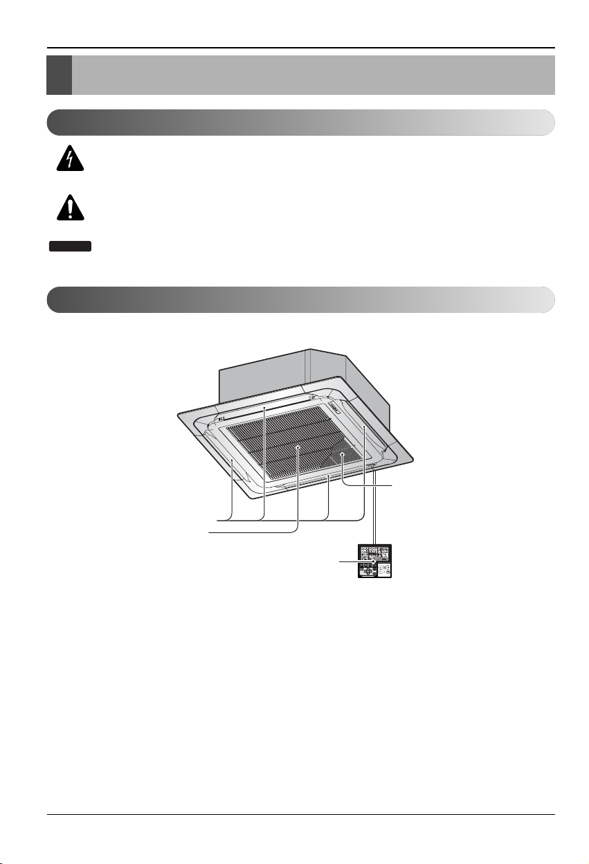
Features
NOTICE
Air Outlet
Air Inlet
Remote
Controller
Anti-bacteria
Installation
Installation Manual 7
Installation
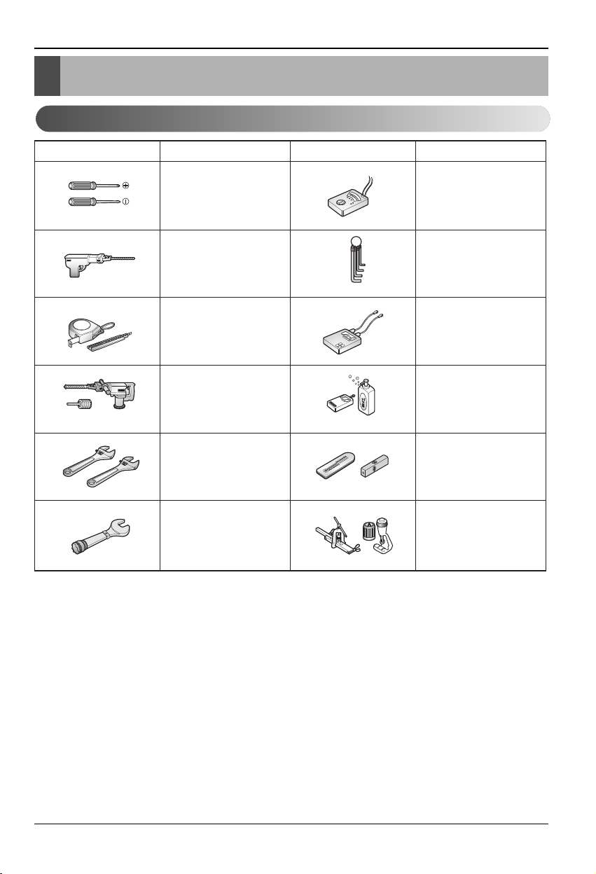
Installation Tools
Figure FigureName
Screw driver
Electric drill
Measuring tape, Knife
Hole core drill
Spanner
Torque wrench
Name
Ohmmeter
Hexagonal wrench
Ammeter
Gas-leak detector
Thermometer,
Horizontal meter
Flaring tool set
8 Ceiling Cassette Air Conditioner
Installation
Installation of Indoor, Outdoor Unit
Selection of the best location
1) Indoor unit
• There should not be any heat source or steam
near the unit.
• There should not be any obstacles to prevent
the air circulation.
• A place where air circulation in the room will
be good.
• A place where drainage can be easily
obtained.
• A place where noise prevention is taken into
consideration.
• Do not install the unit near the door way.
• Ensure the spaces indicated by arrows from
the wall, ceiling, or other obstacles.
• The indoor unit must keep the maintenance
space.
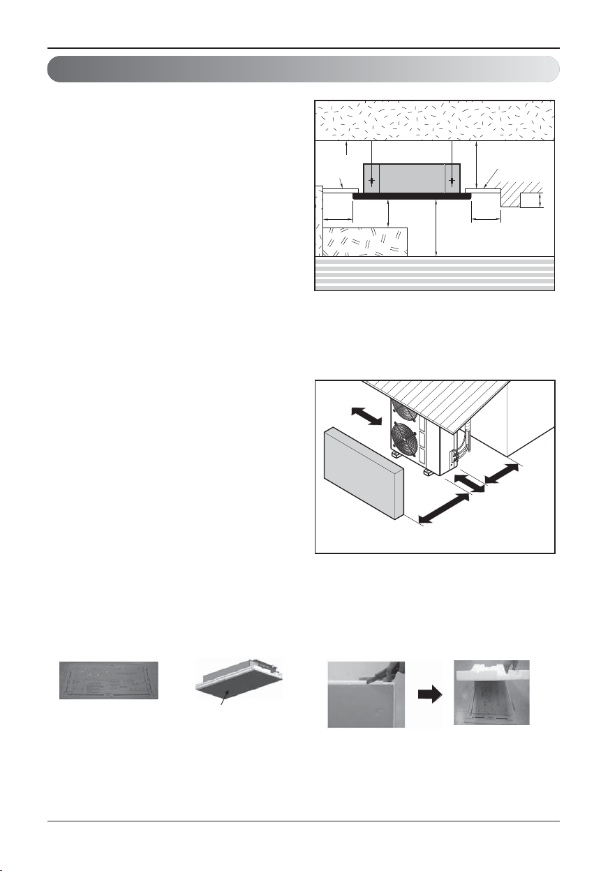
2) Outdoor unit
• If an awning is built over the unit to prevent
direct sunlight or rain exposure, be careful that
heat radiation from the condenser is not
restricted.
• There should not be any animals or plants
which could be affected by hot air discharged.
• Ensure the spaces indicated by arrows from
the wall, ceiling, fence or other obstacles.
Unit:mm
Ceiling
Ceiling Board
Ceiling Board
300 or more
Above 2500
400 or less
1000
or more
500 or
more
500 or
more
300 or less
Floor
More than
300mmm
h Please use an annexed sheet or the
corrugated cardboard on the bottom of
packing as installation sheet.
h When using the bottom sheet, please use it
after separating the installation sheet from
packing of the product floor by using a knife
etc as a picture below.
Annexed sheet
Or
Packing corrugated
cardboard on the
bottom
More than
300mm
Fence or
Sunroof
More than
More than
300mm
300mmm
obstacles
More than 600mm
More than 700mm
Installation
Installation Manual 9
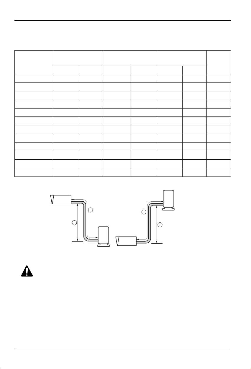
3) Piping length and the elevation
Outdoor unit
Indoor unit
A
B
Outdoor unit
Indoor unit
A
B
CAUTION:
• Rated performance for refrigerant line length of:7.5m
• Capacity is based on standard length and maximum allowance length is on the
basis of reliability.
• Improper refrigerant charge may result in abnormal cycle.
• Oil trap should be installed every 10 meters.
Model
*Additional
refrigerant
(g/m)
Pipe Size
mm(inch)
Length A(m) Elevation B(m)
Gas Liquid Standard Max. Standard Max.
LT-H182QLE0 12.70(1/2”) 6.35(1/4”) 7.5 30 5 20 30
LT-H242QLE0 15.88(5/8”) 6.35(1/4”) 7.5 30 5 20 35
LT-H302PLE0 15.88(5/8") 6.35(1/4") 7.5 50 5 30 25
LT-H362NLE0 15.88(5/8") 6.35(1/4") 7.5 50 5 30 45
LT-H482MLE0 19.05(3/4") 9.52(3/8") 7.5 50 5 30 45
LT-H602MLE0 19.05(3/4") 9.52(3/8") 7.5 50 5 30 50
LT-C182QLE0 12.70(1/2”) 6.35(1/4”) 7.5 30 5 20 30
LT-C242QLE0 15.88(5/8”) 6.35(1/4”) 7.5 30 5 20 35
LT-C302PLE0 15.88(5/8") 6.35(1/4") 7.5 50 5 30 30
LT-C362NLE0 15.88(5/8") 6.35(1/4") 7.5 50 5 30 30
LT-C482MLE0 19.05(3/4") 9.52(3/8") 7.5 50 5 30 55
LT-C602MLE0 19.05(3/4") 9.52(3/8") 7.5 50 5 30 55
10 Ceiling Cassette Air Conditioner
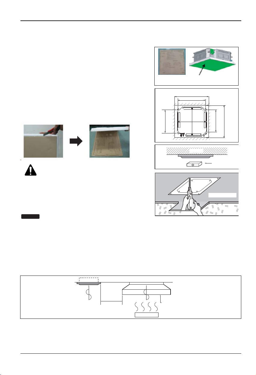
Installation
• Select and mark the position for fixing bolts and piping hole.
• Decide the position for fixing bolts slightly tilted to
the drain direction after considering the direction of
drain hose.
• Drill the hole for anchor bolt on the ceiling.
• The hole size for four anchor bolts is
Ø 14.5mm & 40mm depth.
• When using cardboard on the bottom of packaging,
use after separating installation paper from bottom
of the product packaging using back of a knife as
shown in the picture (TM/TN/TP)
CAUTION:
• This air-conditioner uses a drain pump.
• Horizontly install the unit using a level gauge.
• During the installation, care should be taken not
to damage electric wires.
• Thoroughly study the following installation locations:
1. In such places as restaurants and kitchens, considerable amount of oil steam and flour adhere to
the turbo fan, the fin of the heat exchanger and the drain pump, resulting in heat exchange reduction, spraying, dispersing of water drops, drain pump malfunction, etc.
In these cases, take the following actions:
• Make sure that the ventilation fan for smoke-collecting hood on a cooking table has sufficient
capacity so that it draws oily steam which should not flow into the suction of the air conditioner.
• Make enough distance from a cooking room to install the air conditioner in such a place where it
may not suck in oily steam.
2. Avoid installing air conditioner in such circumstances where cutting oil mist or iron powder is in
suspension in factories, etc.
3. Avoid places where inflammable gas is generated, flows in, is stored or vented.
4. Avoid places where sulfurous acid gas or corrosive gas is generated.
5. Avoid places near high frequency generators.
Ceiling opening dimensions and hanging bolt location
• The dimensions of the paper model for installing are the same as those of the ceiling opening dimensions.
• Please use included paper or cardboard on the bottom of packaging as installation paper
Ceiling board
Level gauge
Ceiling
Unit: mm
875(TM/TN/TP)
585~660(TQ)
787(TM/TN/TP)
517(TQ)
684(TM/TN/TP)
517(TQ)
671(TM/TN/TP)
523(TQ)
875(TM/TN/TP)
585~660(TQ)
840(TM/TN/TP)
570(TQ)
840(TM/TN/TP)
570(TQ)
Included Paper Cardboard on the bottom
of packaging
Use the ventilation fan
for smoke-collecting
hood with sufficient
capacity.
Cooking table
Air conditioner
Take enough
distance
NOTICE
Installation Manual 11
Installation
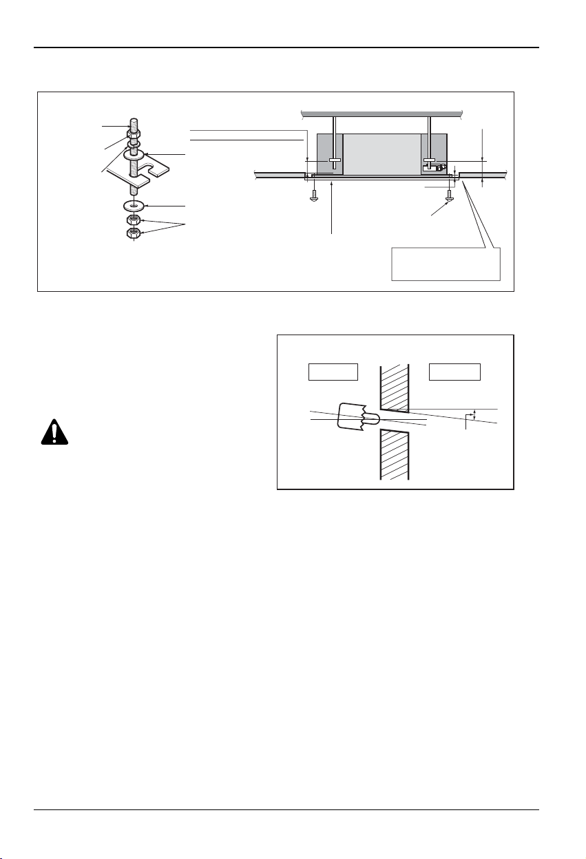
The Indoor Unit Installation
• The following parts is option.
① Hanging Bolt - W 3/8 or M10
② Nut - W 3/8 or M10
③ Spring Washer - M10
④ Plate Washer - M10
• Drill the piping hole on the wall slightly tilted to the
outdoor side using a Ø 70 hole-core drill.
CAUTION:
Tighten the nut and
bolt to prevent unit falling.
Remote Controller Installation
• Although the room temperature sensor is in the indoor unit, the remote controller should be installed in
such places away from direct sunlight and high humidity.
Installation of the remote controller
• Select places that are not splashed with water.
• Select control position after receiving customer approval.
• The room temperature sensor is built in the indoor unit.
• This remote controller equipped with liquid crystal display. If this position is higher or lower, display is difficult to
see.(The standard height is 1.2 ~ 1.5m high)
Routing of the remote controller cord
• Keep the remote controller cord away from the refrigerant piping and the drain piping.
• To protect the remote controller cord from electrical noise, place the cord at least 5cm away from other power
cables (audio equipment, television set, etc.)
• If the remote controller cord is secured to the wall, provide a trap at the top of the cord to prevent water
droplets from running.
Hanging bolt
(W3/8 or M10)
Nut
(W3/8 or M10)
Spring washer
(M10)
Keep the length of the bolt
from the bracket to 40mm
Flat washer for M10
(Attached Insulator,
accessory)
Flat washer for M10
(accessory)
Nut
(W3/8 or M10)
Ceiling board
Air Conditioner body
Keep the length of 31~34mm
between the air conditioner bottom
surface and the ceiling surface
Paper model
for installation
Ceiling
Set screw of
paper model (4 pieces)
Open the ceiling board
along the outer edge of the
paper model
180mm
Ceiling board
Indoor
Wall
Slope gradient for drain
Should be 1/50 ~ 1/100
Outdoor

12 Ceiling Cassette Air Conditioner
Installation
2
2
1
3
3
1. Please fix tightly using provided screw after placing remote controller setup board
on the place where you like to setup.
- Please set it up not to bend because poor setup could take place if setup board bends.
Please set up remote controller board fit to the reclamation box if there is a reclamation box.
- Install the product so as not to make a gap with the wall side and to prevent shaking after the installation.
2. Can set up Wired remote controller cable into three directions.
- Setup direction: the surface of wall reclamation, upper, right
- If setting up remote controller cable into upper and right side, please set up after removing remote
controller cable guide groove.
❈
Remove guide groove with long nose.
①
Reclamation to the surface of the wall
②
Upper part guide groove
③
Right part guide groove
WIRED REMOTE CONTROL INSTALLATION
<Wire guide grooves>
<4 Hole reclamation box> <2 Hole reclamation box>
 Loading...