

LG LT-E1862HL, LT-E1820HL, LT-E2460CL, LT-E1860AA, LT-E2460HL Service Manual
...
Ceiling Cassette
Air Conditioner
SERVICE MANUAL
MODELS: LT-E1820CL/LT-E1820HL
LT-E1860CL/LT-E1860HL
LT-E1860AA
LT-E1862HL
LT-E2460CL/LT-E2460HL
LT-E2460BL
LT-E2462HL/LT-E2462CL
LT-E2460AA
LT-C182ELE0/LT-H182ELE0
LT-H246ELE0/ELF0
LT-C246ELE0/ELF0

Contents
Functions .................................................................................................................................3
Product Specifications (Cooling & Heating)..........................................................................7
Dimensions ..............................................................................................................................9
Refrigeration Cycle Diagram ................................................................................................12
Wiring Diagram ......................................................................................................................14
Operation Details ...................................................................................................................17
Installation of Indoor, Outdoor Unit .....................................................................................20
Cycle .......................................................................................................................................38
Cycle Troubleshooting Guide ...............................................................................................41
Electronic Parts Troubleshooting Guide .............................................................................42
Electronic Control Device .....................................................................................................45
Schematic Digram..................................................................................................................46
Exploded View and Replacement Parts List .......................................................................47
–2–
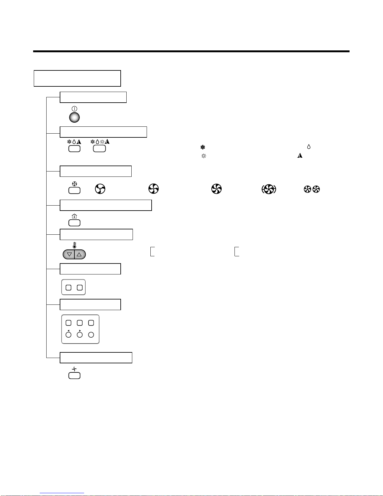
Functions
–3–
Indoor Unit
Operation ON/OFF by Remote controller
Sensing the Room Temperature
Room temperature control
Starting Current Control
Time Delay Safety Control
Indoor Fan Speed Control
Soft Dry Operation Mode
Airflow Direction Control
Auto Operation(Auto Change Over)
Deice (defrost) control (Heating)
Auto Restart
Hot-start Control (Heating)
• The indoor fan stops until the evaporator piping temperature will be reached at 28°C.
Compact and light design
• To install a unit is very convenient because of smaller size
than textile. ( 600 x 600 )
Low noise
• The most advanced low-noise design.
• The adoption of turbo fan and round type heat exchanger
give the quietest operation.
Long life filter
• Long life wrinkle(type) and washable and anti-bacteria filter
is adopted.
Plasma Air Purifying Filter(2HL Only)
High head Drain pump
• Built-in drain pump automatically drains water.
• A standard drain-head height of up to 700mm is possible.
High-Ceiling corresponding Function
• According to the height of ceiling, the RPM of indoor fan
motor is selected to increase air reaching distance.
Central Control(Optional)
•
It is operating individually or totally by central control function.
Group Control(Optional Wiring)
Elevation Grille (Optional)
•
Each controller can control 16 units and 8 controllers can be
connected.
•
It operates maximum 16 units by only one wired remote controller and each unit starts sequentially to prevent overcurrent.
• Auto Elevation Grille is automatically down to height of max 3m.
So it enables to install the indoor unit at high celling space and
Auto Elevation Grille makes you clean the filter easily.
• Room temperature sensor. (Thermistor)
•
Maintains the room temperature in accordance with the Setting Temp.
• Indoor fan is delayed for 5 seconds at the starting.
• Restarting is inhibited for approx. 3 minutes.
• Jet, High, Med, Low
• Intermittent operation of fan at low speed.
• The louver can be set at swing up and down automatically.
• Although the air-conditioner is turned off by a power failure, it is restarted automatically previous operation mode after power supply.
• The setting temperature and desired operation mode are automatically set by fuzzy logic.
• Both the indoor and outdoor fan stops during defrosting.
• Hot start after defrost ends.
–4–
Remote Controller
Operation ON/OFF
Operation Mode Selection
Fan Speed Selection
Room Temperature Display
Temperature Setting
Setting the Timer
Weekly Program
(Cooling
model only)
(Heating
model only)
(Low) (Med) (High)
Cooling Operation Mode ( )
Heating Operation Mode ( ) Auto Operation Mode ( )
Soft Dry Operation Mode ( )
Fan Operation Mode
HI JET AUTOMEDLO
Program Holiday
SET/CLR
MinHour
Week
Timer CancelTimer Cancel
: High:39°C ↔ LOW:11°C
: Fan Operates without cooling & heating
Cooling Heating
Down to 18°C
Up to 30°C
Down to 16°C
Up to 30°C
–5–
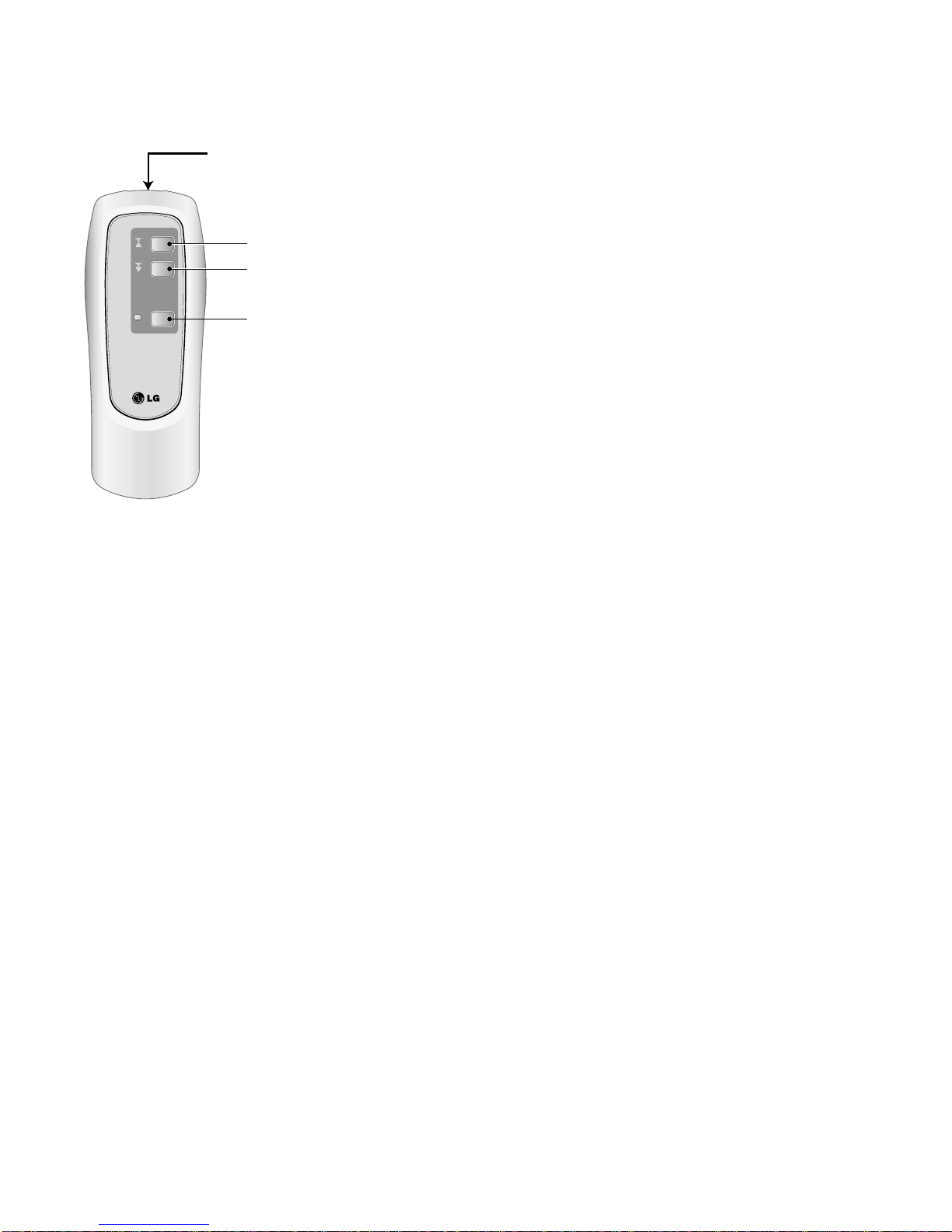
■ ELEVATION GRILL (REMOTE CONTROLLER_Accessory)
• How to Use Remote Controller
• Main Components of Lift Grill
As for operation of Remote Controller, use it by directing the transmitter part of Remote Controller to the receiver part of front panel
directly under front panel.
• Do not drop it down or into water. Or else there is worry about
trouble failure.
• Do not press hard the Remote Controller button with nail (ballpoint pen or other sharp substance). Or else there is worry
about trouble failure.
• In case when obstacle such as curtain hides the signal reception
part of receiver in between the space interval, Remote Controller
operation is infeasible.
➀ Lift grill front panel assembly
➁ Bolts for installation (4 EA, P/No. 3A00255K)
➂ Instruction manual
➃ Remote Controller for lift grill
Ascend
Signal transmitter
Descend
Stop
–6–
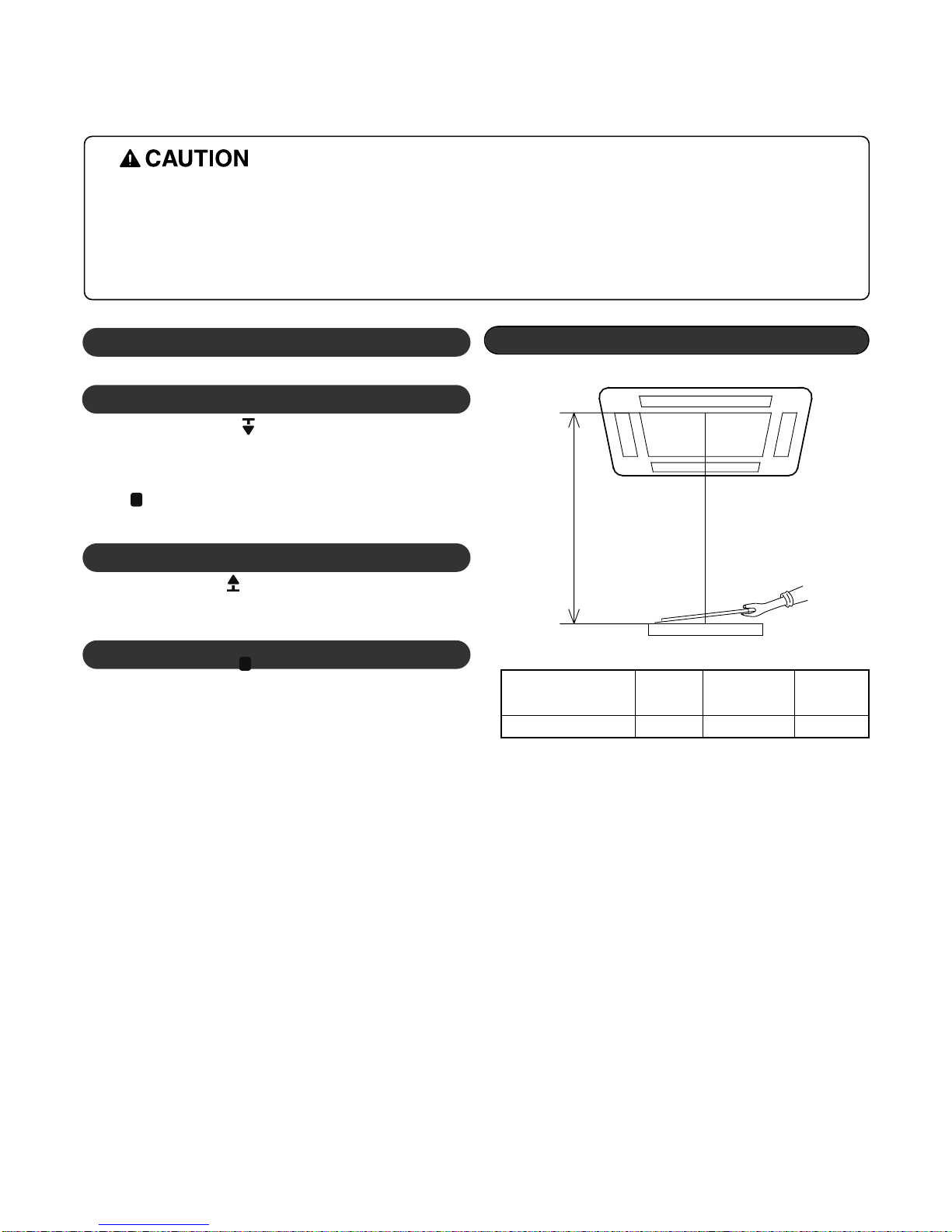
Automatic stop distance
✳
If you want to change automatic distance setting,
consult with your sale agency.
Automatic Stop Distance of Grill
Ceiling height Low
Medium
High
(
Height: 3~4 m)
Automatic stop distance
1.5±0.5m 2.5±0.5m 3.5±0.5m
- Depress the down button( ).
Then suction grill descends and stops automatically at a certain
distance.
- You may stop it at wanted distance point by depressing the stop button ( ) when descending.
- Depress the up button( ).
Then suction grill goes up and enters into the front panel.
1. Stop the Air Conditioner Operation
2. Descend the Suction Grill
3. Raise the Suction Grill
- Depress the stop button( ).
Make use of this when you want to stop it at your wished position.
4. Stop the Suction Grill during Rising
• Always stop the air conditioner operation for safety before operating lift grill.
• Take heed _ there is worry about dust fall etc. when suction grill descends.
• In case when the set automatic stop distance goes wrong, check the set value of operation panel and con-
firm if there is neither obstacle nor mankind.
• When you are not to remove obstacle, stop the operation before touching the obstacle.
• How to Operate the Lift Grill
Model
1, 220-240, 50
4,536(5,274)
18,000
-
-
1,900
-
9.5
-
53
-
2.39
13
50
1.9
O
X
4
O
O
O
O
O
4
O
X
O
O
O
O
Optional
O
O
1,900
570 x 570 x 269
670 x 670 x 30
870 x 655 x 320
19(16.5+2.5)
60
14:3*2.5
18:4*0.75
1/4(6.35mm)
5/8(15.88mm)
50
30
FoamPE/5mm
ø25/32
1, 220-240, 50
4,536(5,274)
18,000
-
-
1,900
-
9.5
-
53
-
2.39
13
50
1.9
O
X
4
O
O
O
O
O
4
O
X
O
O
O
O
Optional
O
X
1,900
570 x 570 x 269
670 x 670 x 30
870 x 655 x 320
19(16.5+2.5)
60
14:3*2.5
18:4*0.75
1/4(6.35mm)
5/8(15.88mm)
50
30
FoamPE/5mm
ø25/32
1, 220-240, 50
4,536(5,274)
18,000
4,536(5,274)
18,000
2,050
1,850
9.5
9.0
53
53
2.21
2.85
13
50
1.9
O
O
4
O
O
O
O
O
4
O
O
O
O
O
O
Optional
O
X
1,800
570 x 570 x 269
670 x 670 x 30
870 x 655 x 320
19(16.5+2.5)
61
14:3*2.5
18:6*0.75
1/4(6.35mm)
5/8(15.88mm)
50
30
FoamPE/5mm
ø25/32
1, 220-240, 50
4,536(5,274)
18,000
4,536(5,274)
18,000
2,050
1,850
9.5
9.0
53
53
2.21
2.85
13
50
1.9
O
O
4
O
O
O
O
O
4
O
O
O
O
O
O
Optional
O
O
1,800
570 x 570 x 269
670 x 670 x 30
870 x 655 x 320
19(16.5+2.5)
61
14:3*2.5
18:6*0.75
1/4(6.35mm)
5/8(15.88mm)
50
30
FoamPE/5mm
ø25/32
1, 220, 60
4,536(5,274)
18,000
-
-
1,970
9
-
53
-
2.30
13
50
1.9
O
X
4
O
O
O
O
O
4
O
X
O
O
O
O
Optional
O
X
1,050
570 x 570 x 269
670 x 670 x 30
870 x 655 x 320
19
60
14:3*2.5
18:4*0.75
1/4(6.35mm)
5/8(15.88mm)
50
30
FoamPE/5mm
ø25/32
1, 220, 60
4,536(5,274)
18,000
4,536(5,274)
18,000
1,900
1,900
8.8
8.8
53
53
2.39
2.78
13
50
1.9
O
O
4
O
O
O
O
O
4
O
O
O
O
O
O
Optional
O
X
1,910
570 x 570 x 269
670 x 670 x 30
870 x 655 x 320
19
61
14:3*2.5
18:6*0.75
1/4(6.35mm)
5/8(15.88mm)
50
30
FoamPE/5mm
ø25/32
LT-E2460AA LT-E1860CL LT-E1860HL LT-E1862HL
LT-E1820CL
LT-C182ELE0
LT-E1820HL
LT-H182ELE0
Power Supply ø, V, Hz
Capacity Cooling kcal/h(W)
Btu/h
Heating kcal/h(W)
Btu/h
Input Cooling W
Heating W
Running Current Cooling A
Heating A
Starting Current Cooling A
Heating A
E.E.R kcal/h(W)
C.O.P W/W
Air Circulation Indoor m
3
/min
Outdoor m
3
/min
Moisture Removal l / h
Air-Flow Direction Control
Heating Operation Mode
Fan Speeds (steps)
Auto Operation (Changeover)
Forced Operation
Jet Cool
Soft Dry Operation
Timer Delay Safety Function
Feature Air Deflection (Way)
Self Diagnosis
Hot start
Auto Restart
Air refresh (Hole)
High Ceiling
Group Control (Optional wiring)
Central Control
Wired remote controller (with weekly Program)
Plasma A/Cleaner
Refrigerant(R-22) Charge g
Dimensions Indoor mm
(W x D x H) Panel mm
Outdoor mm
Net Weight Indoor kg
Outdoor kg
Main Power Cord AWG#:P*mm
2
Connection Cable AWG#:P*mm
2
Service Valve Liquid (inch)
Gas (inch)
Installation Pipe Length (m)
Elevation (m)
Insulation(material/thickness)
Drain Hose(I.D/O.D) mm
Product Specifications (Cooling & Heating)
–7–
–8–
Power Supply ø, V, Hz
Capacity Cooling kcal/h(W)
Btu/h
Heating kcal/h(W)
Btu/h
Input Cooling W
Heating W
Running Current Cooling A
Heating A
Starting Current Cooling A
Heating A
E.E.R kcal/h(W)
C.O.P W/W
Air Circulation Indoor m
3
/min
Outdoor m
3
/min
Moisture Removal l / h
Air-Flow Direction Control
Heating Operation Mode
Fan Speeds (steps)
Auto Operation (Changeover)
Forced Operation
Jet Cool
Soft Dry Operation
Timer Delay Safety Function
Feature Air Deflection (Way)
Self Diagnosis
Hot start
Auto Restart
Air refresh (Hole)
High Ceiling
Group Control (Optional wiring)
Central Control
Wired remote controller (with weekly Program)
Plasma A/Cleaner
Refrigerant(R-22) Charge g
Dimensions Indoor mm
(W x D x H) Panel mm
Outdoor mm
Net Weight Indoor kg
Outdoor kg
Main Power Cord AWG#:P*mm
2
Connection Cable AWG#:P*mm
2
Service Valve Liquid (inch)
Gas (inch)
Installation Pipe Length (m)
Elevation (m)
Insulation(material/thickness)
Drain Hose(I.D/O.D) mm
Model
LT-E2460CL
LT-C246ELE0
LT-E2460HL LT-E2460BL
LT-E2462HL
LT-H246ELE0/ELF0
LT-E2462CL
LT-E2460AA
1, 220-240, 50
5,871(6,827)
23,300
-
-
2,600
-
13.5
-
62
-
2.26
-
15.5
50
2.9
O
X
4
O
O
O
O
O
4
O
X
O
O
O
O
Optional
O
X
1,900
570 x 570 x 269
670 x 670 x 30
870 x 655 x 320
19(16.5+2.5)
61
14:3*2.5
18:4*0.75
1/4(6.35mm)
5/8(15.88mm)
50
30
FoamPE/5mm
ø25/32
1, 220-240, 50
5,871(6,827)
23,300
5,922(6,886)
23,500
2,600
2,600
13.5
13.5
62
60
2.26
2.65
15.5
50
2.9
O
O
4
O
O
O
O
O
4
O
O
O
O
O
O
Optional
O
X
1,900
570 x 570 x 269
670 x 670 x 30
870 x 655 x 320
19(16.5+2.5)
62
14:3*2.5
18:6*0.75
1/4(6.35mm)
5/8(15.88mm)
50
30
FoamPE/5mm
ø25/32
1, 220-240, 50
5,871(6,827)
23,300
5,922(6,886)
23,500
2,600
2,600
13.5
13.5
62
60
2.26
2.65
15.5
50
2.9
O
O
4
O
O
O
O
O
4
O
O
O
O
O
O
Optional
O
X
1,900
570 x 570 x 269
670 x 670 x 30
870 x 655 x 320
19(16.5+2.5)
62
14:3*2.5
18:6*0.75
1/4(6.35mm)
5/8(15.88mm)
50
30
FoamPE/5mm
ø25/32
1, 220-240, 50
5,871(6,827)
23,300
5,922(6,886)
23,500
2,600
2,600
13.5
13.5
62
60
2.26
2.65
15.5
50
2.9
O
O
4
O
O
O
O
O
4
O
O
O
O
O
O
Optional
O
O
1,900
570 x 570 x 269
670 x 670 x 30
870 x 655 x 320
19(16.5+2.5)
62
14:3*2.5
18:6*0.75
1/4(6.35mm)
5/8(15.88mm)
50
30
FoamPE/5mm
ø25/32
1, 220-240, 50
5,871(6,827)
23,300
-
-
2,600
-
13.5
-
62
-
2.26
-
15.5
50
2.9
O
X
4
O
O
O
O
O
4
O
X
O
O
O
O
Optional
O
O
1,900
570 x 570 x 269
670 x 670 x 30
870 x 655 x 320
19(16.5+2.5)
61
14:3*2.5
18:6*0.75
1/4(6.35mm)
5/8(15.88mm)
50
30
FoamPE/5mm
ø25/32
Dimensions
–9–
269
67055
570
269
190.5
160
52
90
90
120.4
30
521
670
570
450
40
110 110
670
670
CLOSE OPEN OPEN CLOSE
(1) Indoor Unit
–10–
LT-H***ELE0
LT-H***FLE0
LT-H***DLE0
W
D
H
W mm 670 850 950
Hmm909090
D mm 670 850 950
(unit : mm)
Model
LT-H***ELE0 LT-H***FLE0 LT-H***DLE0
DIM
Unit
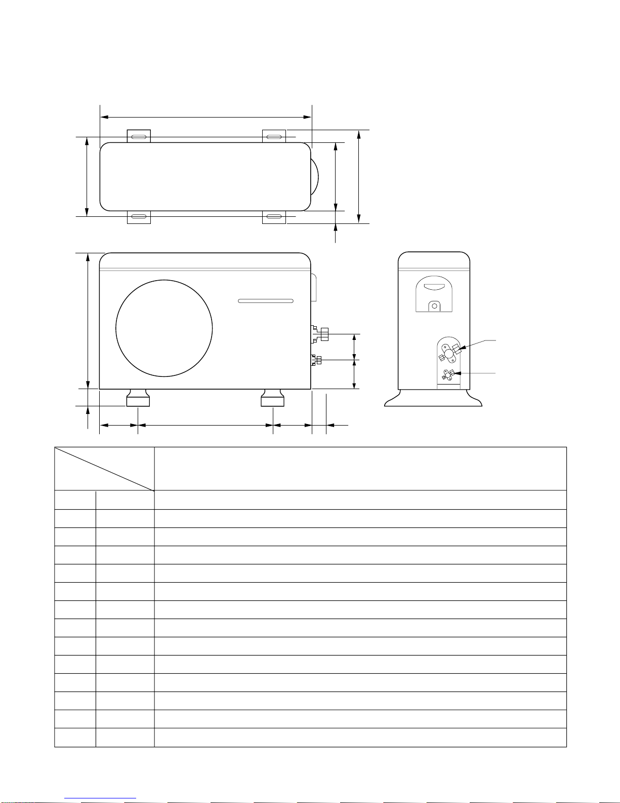
(2) Outdoor Unit
–11–
Gas side
3-way valve
Liquid side
3-way valve
W
L6L7 L8 L9
L4
L11
L10
D
L1
L2
L5
L3
MODEL
DIM
W mm 870
H mm 655
D mm 320
L1 mm 370
L2 mm 25
L3 mm 340
L4 mm 630
L5 mm 25
L6 mm 546
L7 mm 162
L8 mm 162
L9 mm 54
L10 mm 74.5
L11 mm 79
All Models
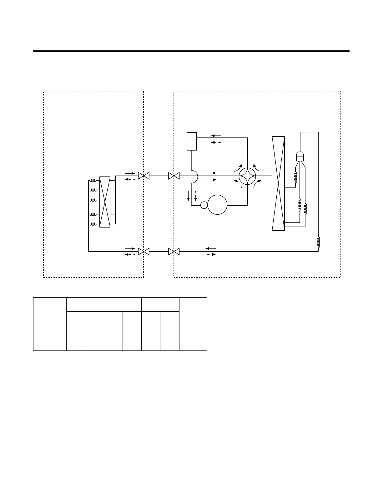
Refrigeration Cycle Diagram
• HEAT PUMP
• Rated performance for refrigerant line length of: 7.5m
• If 18K Capacity is installed at a distance of 15m, 187.5g of refrigerant
should be added ....................................................(15-7.5)x25g
–12–
INDOOR UNIT
H/EX
Liquid SideLiquid SideGas Side
COMPRESSOR
VALVE REVERSING
ACCUM.
H/EX
Gas SideGas SideLiquid Side
CAPI C1
CAPI A
CAPI B
Heating Cooring
CAPI C2
(
OUTDOOR UNIT
GAS LIQUID
Elevation (m)
Length (m)
* Additional
refrigerant
(g/m)
Pipe Size
Rated Rated
Max. Max.
Capacity
18K 5/8" 1/4"
7.
550 5 30 25
24K 5/8" 1/4"
7.5 50 5 30 30
–13–
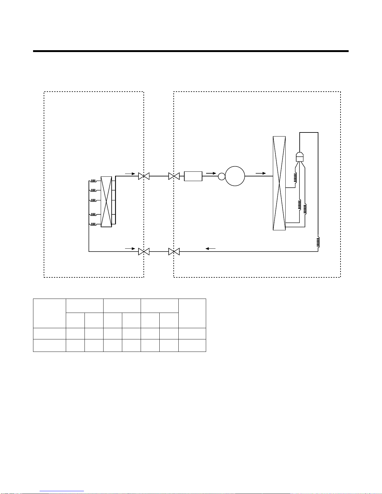
• COOLING ONLY
• Rated performance for refrigerant line length of: 7.5m
• If 18K Capacity is installed at a distance of 15m, 187.5g of refrigerant
should be added ....................................................(15-7.5)x25g
INDOOR UNIT
H/EX
Liquid SideLiquid SideLiquid Side
COMPRESSOR
ACCUM.
H/EX
Gas SideGas SideGas Side
CAPI C1
CAPI A
CAPI B
CAPI C2
OUTDOOR UNIT
GAS LIQUID
Elevation (m)
Length (m)
* Additional
refrigerant
(g/m)
Pipe Size
Rated Rated
Max. Max.
Capacity
18K 5/8" 1/4" 7.5 50 5 30 25
24K 5/8" 1/4" 7.5 50 5 30 30
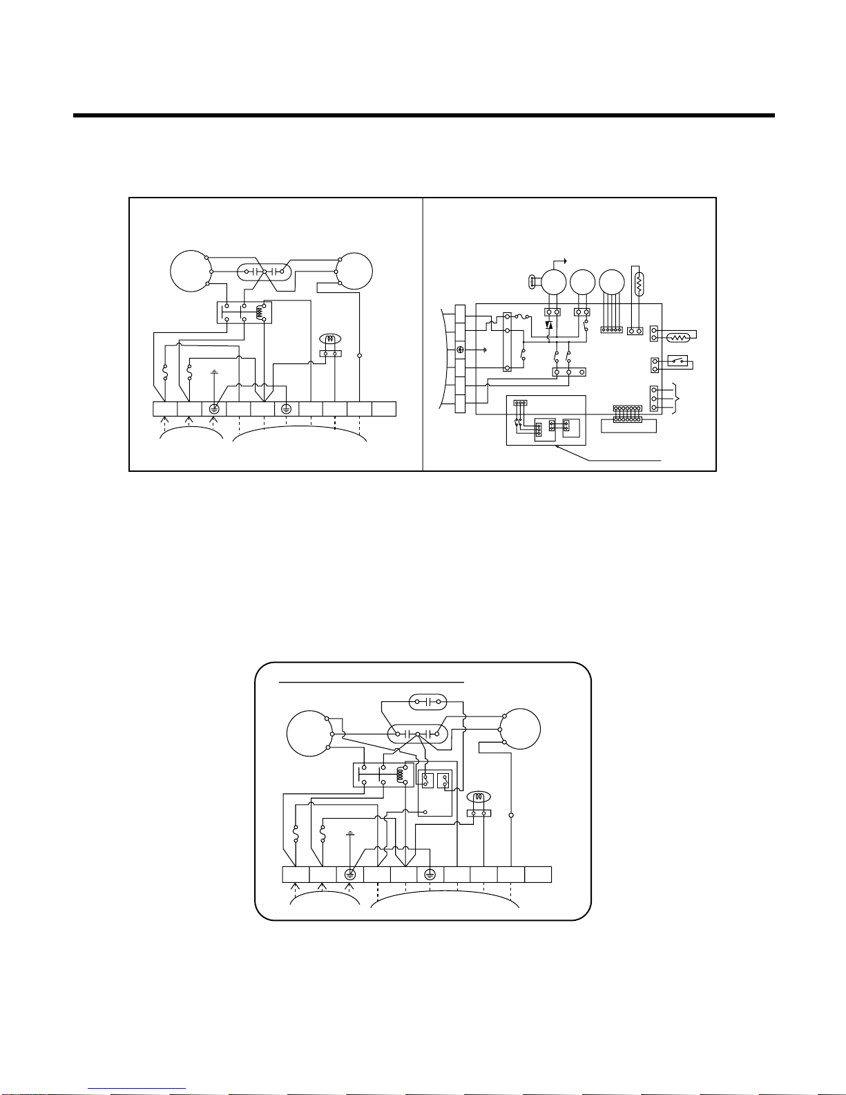
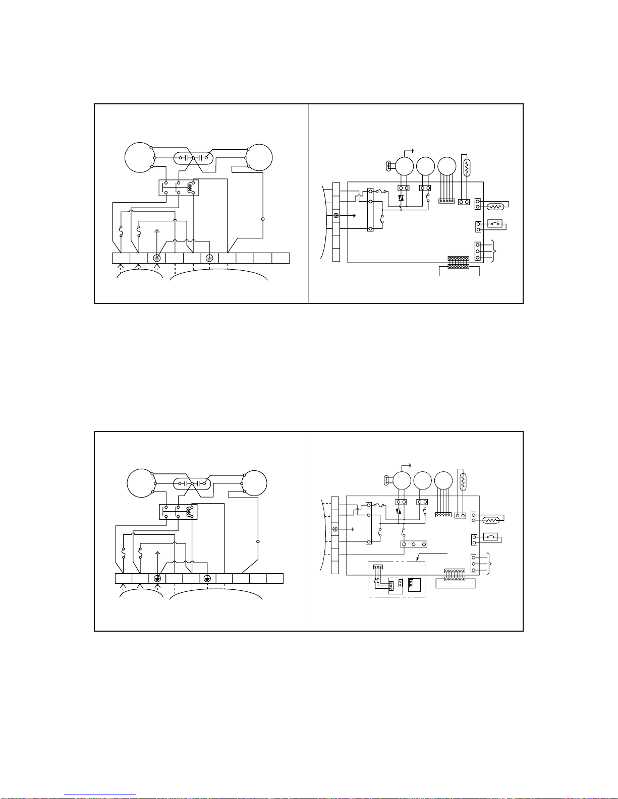
Wiring Diagram
• HEAT PUMP
Model No.: LT-E1860HL/ LT-E1862HL/ LT-E2460HL/ LT-E2462HL/ LT-E2460BL
LT-H182ELEO/LT-H246ELE0/LT-H246ELF0
LT-E2460HL(Australia only)
–14–
OUTDOOR WIRING DIAGRAM INDOOR WIRING DIAGRAM
COMP
R
S
H
42861
0
CF
BL
YL
OR
BK
TB2
BR
BR
BR
BR
BL
BL
BL
BL
BL
GN/YL
GN/YL
BK
BK
RD
CAPACITOR
REVERSING
VALVE
RD
C
POWER
RELAY
FAN
MOTOR
FUSE 5A
FUSE 5A
POWER
INPUT
TO INDOOR UNIT
TERMINAL
BLOCK
1(L)2(N
)
3(L)4(N
)
5
6
7
8
INDOOR
MOTOR
DRAIN
PUMP
STEP
MOTOR
TEMP.
THERMISTOR
PIPE
THERMISTOR
REMOTE
CONTROL
FLOAT S/W
CN - DISP
DISPLAY PCB
Only for LT-Exxx2HL
AIR
CLEANER
H.V. ASSY
DOOR S/W
TERMINAL
BLOCK
TO OUTDOOR UNIT
BR
YL
BK
OR
BL
BL
BR
GN/YL
RD
BK
YL
BL
GN
/
YL
OUT FAN
COMP
4 WAY
RD
BK
WH
RD
BK
3
(
L
)
4
(
N
)
5 6 7
FUSE T3.15A
OUTDOOR WIRING DIAGRAM
COMP
R
S
H
42861
0
CF
B
L
YL
YL
WH
YL
OR
BK
TB2
BR
BR
BR
BR
BL
BL
BL
BL
BL
BL
GN/YL
GN/YL
BK
BK
RD
CAPACITOR
S/CAPACITOR
REVERSING
VALVE
RD
C
POWER
RELAY
FAN
MOTOR
FUSE 5A
FUSE 5A
POWER
INPUT
TO INDOOR UNIT
TERMINAL
BLOCK
3854A20119A
1(L)2(N
)
3(L)4(N
)
5
6
7
8
3
RYCOMP
RYS/CAPA
CN-POWER
434
–15–
• COOLING ONLY
Model No.: LT-E1860CL/LT-E1860AA/LT-C182ELE0
Model No.: LT-E2460CL/LT-E2462CL/LT-E2460AA/LT-C246ELE0
OUTDOOR WIRING DIAGRAM INDOOR WIRING DIAGRAM
INDOOR
MOTOR
DRAIN
PUMP
STEP
MOTOR
TEMP.
THERMISTOR
PIPE
THERMISTOR
REMOTE
CONTROL
FLOAT S/W
CN - DISP
DISPLAY PCB
TERMINAL
BLOCK
TO OUTDOOR UNIT
BR
YL
BK
OR
BL
BL
BR
GN/YL
RD
BL
GN
/
YL
COMP
3
(
L
)
4
(
N
)
5 6 7
FUSE T3.15A
COMP
R
S
H
42861
0
CF
BL
YL
OR
BK
TB2
BR
BR
BR
BR
BL
BL
BL
BL
BL
GN/YL
GN/YL
BK
RD
CAPACITOR
RD
C
POWER
RELAY
FAN
MOTOR
FUSE 5A
FUSE 5A
POWER
INPUT
TO INDOOR UNIT
TERMINAL
BLOCK
1(L)2(N
)
3(L)4(N
)
5
6
7
8
OUTDOOR WIRING DIAGRAM INDOOR WIRING DIAGRAM
INDOOR
MOTOR
DRAIN
PUMP
STEP
MOTOR
TEMP.
THERMISTOR
PIPE
THERMISTOR
REMOTE
CONTROL
FLOAT S/W
CN - DISP
DISPLAY PCB
LT-E
***
2
HL ONLY
AIR
CLEANER
H.V. ASSY
DOOR S/W
TERMINAL
BLOCK
TO OUTDOOR UNIT
BR
YL
BK
OR
BL
BL
BR
GN/YL
RD
YL
BL
GN
/
YL
COMP
RD
BK
WH
RD
BK
3(L) 4(N)
5 6 7
FUSE T3.15A
OUT FAN
COMP
R
S
H
42861
0
CF
BL
YL
OR
BK
TB2
BR
BR
BR
BR
BL
BL
BL
BL
BL
GN/YL
GN/YL
BK
RD
CAPACITOR
RD
C
POWER
RELAY
FAN
MOTOR
FUSE 5A
FUSE 5A
POWER
INPUT
TO INDOOR UNIT
TERMINAL
BLOCK
1(L)2(N
)
3(L)4(N
)
5
6
7
8
–16–
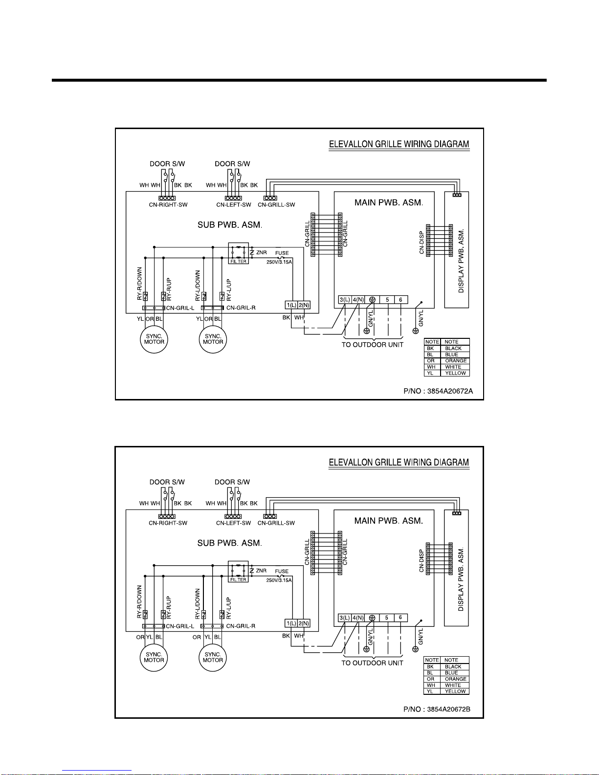
■ ELEVATION GRILL WIRING DIAGRAM (INDOOR)
LT-H***DLE0/LT-C***DLE0
LT-H***ELE0/LT-C***ELE0
LT-H***FLE0/LT-C***FLE0
–17–
Operation Details
(1) The function of main control
1. Time Delay Safety Control
• 3min The compressor is ceased for 3minutes to balance the pressure in the refrigeration cycle.
(Protection of compressor)
• 5sec
Vertical air flow direction control louvers open in 5 seconds to prevent noise between louvers and wind.
• 30sec The 4-way valve is ceased for 30sec. to prevent the refrigerant-gas abnormal noise when the Heating
operation is OFF or switched to the other operation mode while compress is off.
While compressor is running, it takes 3~5 seconds to switch.
2. Auto Swing Control
• This function is to swing the louver up and down automatically.
3. Air-Filter Checking Control
• 'Filter' will display in the remote controller display and main body display when an air-filter is polluted. Then clean
the air-filter for reference to Owners Manual.
4. Soft-Dry Operation
• The indoor fan speed is automatically set to the low, so the shift of the indoor fan speed is impossible because of
already being set to the best speed for Dry Operation by Micom Control.
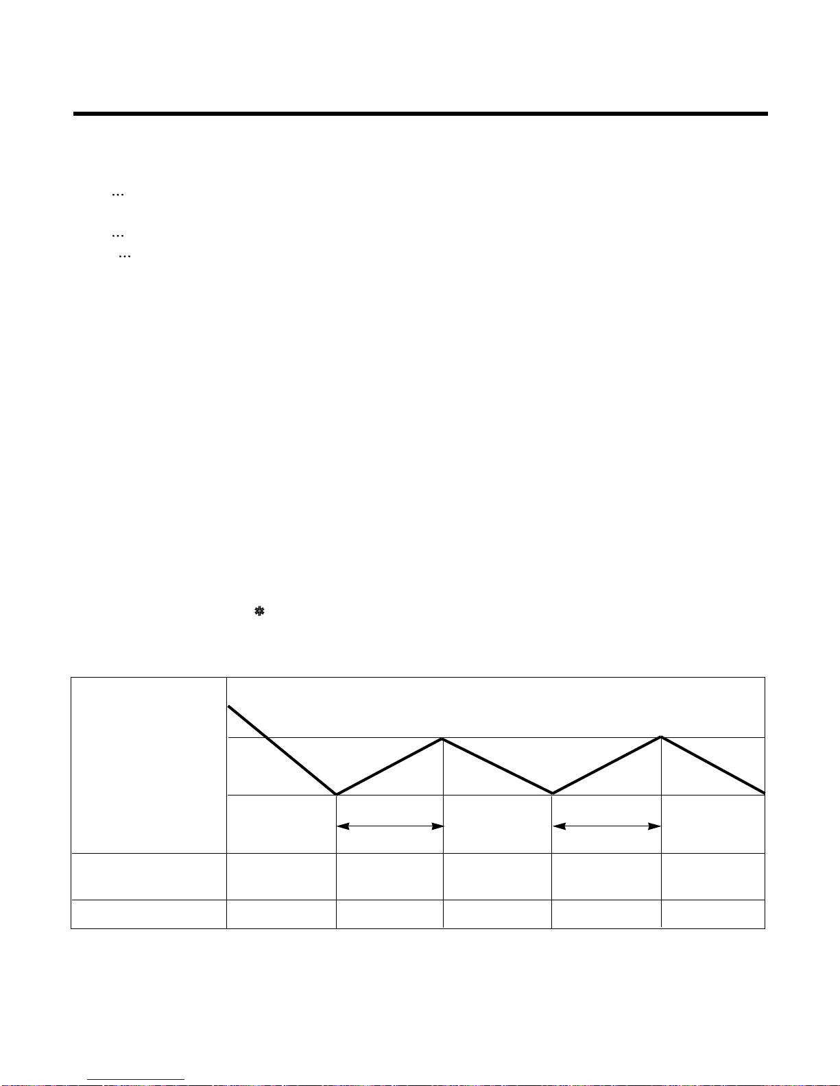
5. Cooling Mode Operation
• When selecting the Cooling( ) Mode Operation, the unit will operate according to the setting by the remote con-
troller and the operation diagram is as following
Intake Air temp.
SET TEMP.+0.5°C
(COMP. ON)
SET TEMP. -0.5°C
(COMP. OFF) More than More than
3 minutes 3 minutes
Selecting Selecting Selecting
fan speed fan speed fan speed
COMPRESSOR ON OFF ON OFF ON
INDOOR FAN Low Low
–18–
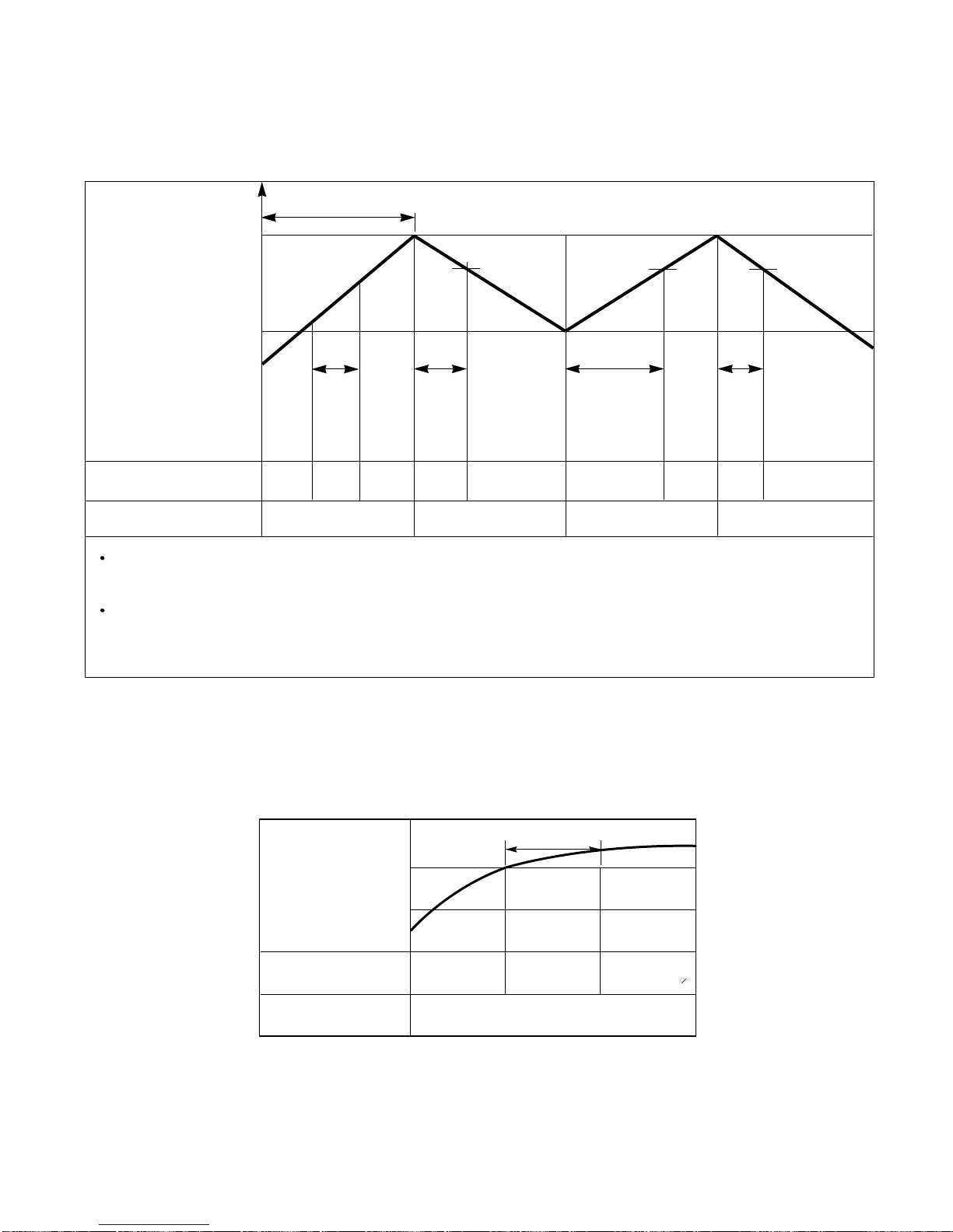
Intake Air temp.
Setting temp.+3°C
(Compressor OFF)
Setting temp.
(Compressor ON)
INDOOR FAN
COMPRESSOR ON OFF ON OFF
A point; While the indoor Heat-Exchanger temperature is higher than 40°C fan operates at low speed, when
it becomes lower than 40˚C fan stops.
B point; When the indoor Heat-Exchanger temperature is higher than 42°C, fan operates at selected fan
speed, when it becomes lower than 39°C, the fan operates at low speed.
6. Heating Mode Operation
The unit will operate according to the setting by the remote controller and the operation diagram is shown as follows.
(Hot Start)
Low
OFF
Selected
Fan Speed
minimum 3min
Selecting fan
speed
LowLowLow OFF OFF
minimum
10sec.
1min
A
A
minimum
1min.
minimum
10sec.
B
7. Hot-Start Control
• The indoor fan stops until the evaporator piping temperature reaches to 25°C.
• If the evaporator piping temperature drops below 22°C, indoor fan stops again.
• The operation diagram is as follows.
PIPING
TEMPERATURE
1min
COMPRESSOR
INDOOR FAN
ON
OFF LOW
Selected
fan speed
22°C
25°C
 Loading...