

Page 1

Ceiling Cassette Air Conditioner
SVC MANUAL(Exploded View)
CAUTION
Before Servicing the unit, read the safety precautions in General SVC manual.
Only for authorized service personnel.
Internal Use Only
http://biz.lgservice.com
MODEL : LT-E1820CL/LT-E1820HL
LT-E1860CL/LT-E1860HL
LT-E1860AA
LT-E1862HL/BA
LT-E2460CL/LT-E2460HL
LT-E2460BL
LT-E2462HL/LT-E2462CL/BA
LT-E2460AA
LT-C182ELE0/LT-H182ELE0
LT-H246ELE0/ELF0
LT-C246ELE0/ELF0
Page 2

Contents
Functions .................................................................................................................................3
Product Specifications (Cooling & Heating)..........................................................................7
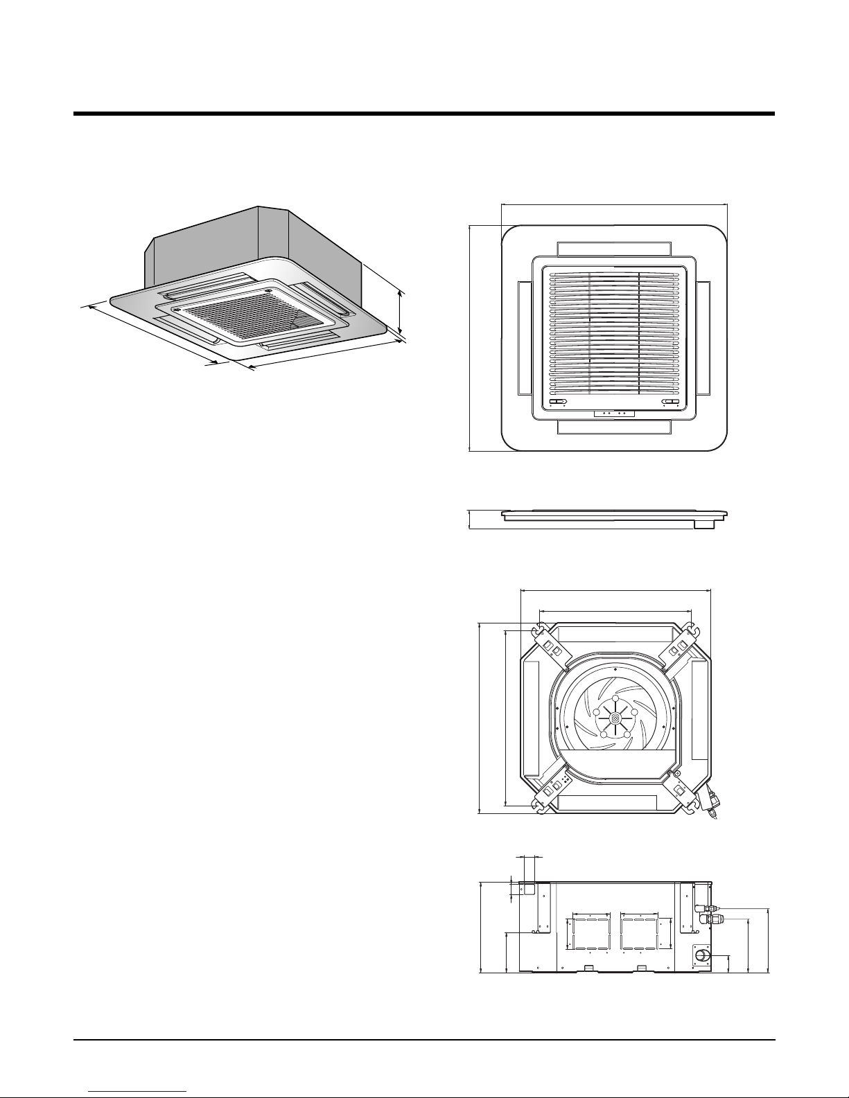
Dimensions ..............................................................................................................................9
Refrigeration Cycle Diagram ................................................................................................12
Wiring Diagram ......................................................................................................................14
Operation Details ...................................................................................................................17
Installation of Indoor, Outdoor Unit .....................................................................................20
Cycle .......................................................................................................................................38
Cycle Troubleshooting Guide ...............................................................................................41
Electronic Parts Troubleshooting Guide .............................................................................42
Electronic Control Device .....................................................................................................45
Schematic Digram ..................................................................................................................46
Exploded View ........................................................................................................................47
- 2 -
Copyright ©2008 LG Electronics. Inc. All right reserved.
Only for training and service purposes
LGE Internal Use Only
Page 3
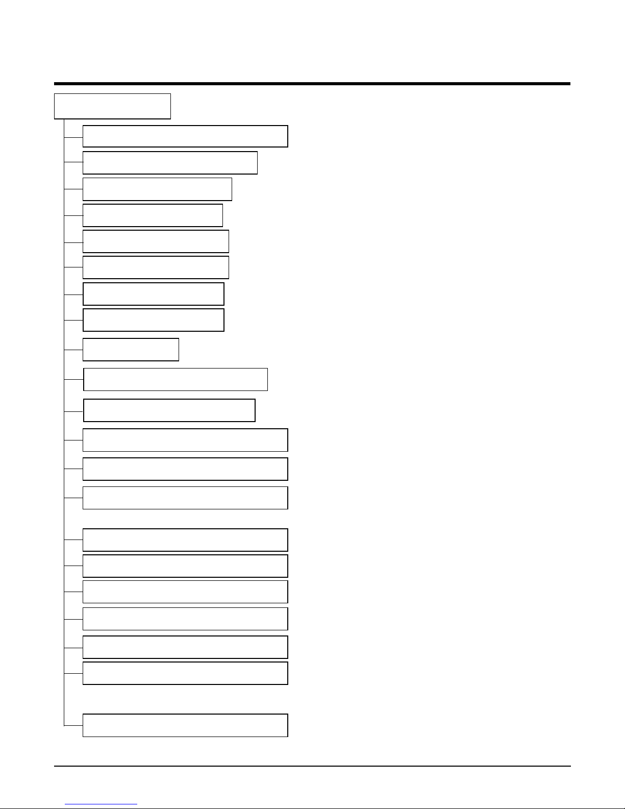
Functions
- 3 -
Copyright ©2008 LG Electronics. Inc. All right reserved.
Only for training and service purposes
LGE Internal Use Only
Indoor Unit
Operation ON/OFF by Remote controller
Sensing the Room Temperature
Room temperature control
Starting Current Control
Time Delay Safety Control
Indoor Fan Speed Control
Soft Dry Operation Mode
Airflow Direction Control
Auto Operation(Auto Change Over)
Deice (defrost) control (Heating)
Auto Restart
Hot-start Control (Heating)
• The indoor fan stops until the evaporator piping temperature will be reached at 28°C.
Compact and light design
• To install a unit is very convenient because of smaller size
than textile. ( 600 x 600 )
Low noise
• The most advanced low-noise design.
• The adoption of turbo fan and round type heat exchanger
give the quietest operation.
Long life filter
• Long life wrinkle(type) and washable and anti-bacteria filter
is adopted.
Plasma Air Purifying Filter(2HL Only)
High head Drain pump
• Built-in drain pump automatically drains water.
• A standard drain-head height of up to 700mm is possible.
High-Ceiling corresponding Function
• According to the height of ceiling, the RPM of indoor fan
motor is selected to increase air reaching distance.
Central Control(Optional)
•
It is operating individually or totally by central control function.
Group Control(Optional Wiring)
Elevation Grille (Optional)
•
Each controller can control 16 units and 8 controllers can be
connected.
•
It operates maximum 16 units by only one wired remote controller and each unit starts sequentially to prevent overcurrent.
• Auto Elevation Grille is automatically down to height of max 3m.
So it enables to install the indoor unit at high celling space and
Auto Elevation Grille makes you clean the filter easily.
• Room temperature sensor. (Thermistor)
•
Maintains the room temperature in accordance with the Setting Temp.
• Indoor fan is delayed for 5 seconds at the starting.
• Restarting is inhibited for approx. 3 minutes.
• Jet, High, Med, Low
• Intermittent operation of fan at low speed.
• The louver can be set at swing up and down automatically.
• Although the air-conditioner is turned off by a power failure, it is restarted automatically previous operation mode after power supply.
• The setting temperature and desired operation mode are automatically set by fuzzy logic.
• Both the indoor and outdoor fan stops during defrosting.
• Hot start after defrost ends.
Page 4
- 4 -
Copyright ©2008 LG Electronics. Inc. All right reserved.
Only for training and service purposes
LGE Internal Use Only
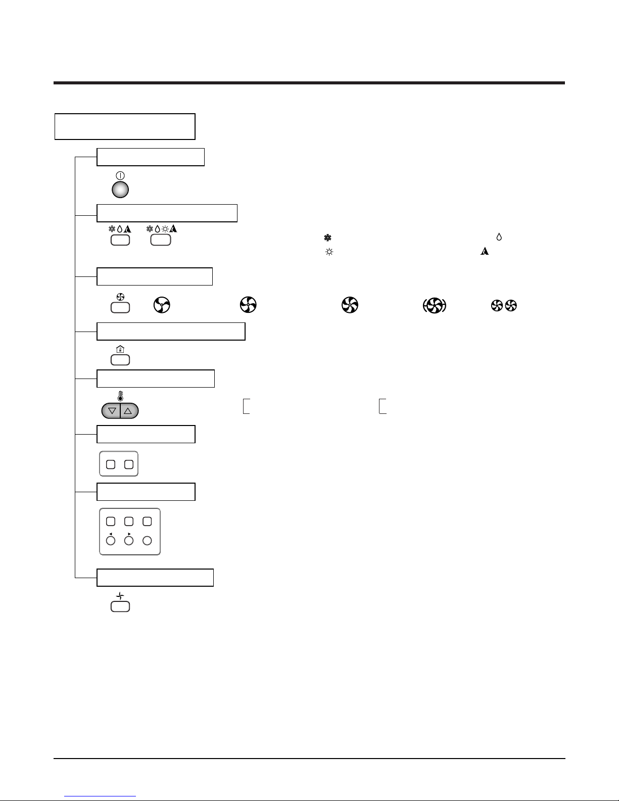
Remote Controller
Operation ON/OFF
Operation Mode Selection
Fan Speed Selection
Room Temperature Display
Temperature Setting
Setting the Timer
Weekly Program
(Cooling
model only)
(Heating
model only)
(Low) (Med) (High)
Cooling Operation Mode ( )
Heating Operation Mode ( ) Auto Operation Mode ( )
Soft Dry Operation Mode ( )
Fan Operation Mode
HI JET AUTOMEDLO
Program Holiday
SET/CLR
MinHour
Week
Timer CancelTimer Cancel
: High:39°C ↔ LOW:11°C
: Fan Operates without cooling & heating
Cooling Heating
Down to 18°C
Up to 30°C
Down to 16°C
Up to 30°C
Page 5
- 5 -
Copyright ©2008 LG Electronics. Inc. All right reserved.
Only for training and service purposes
LGE Internal Use Only
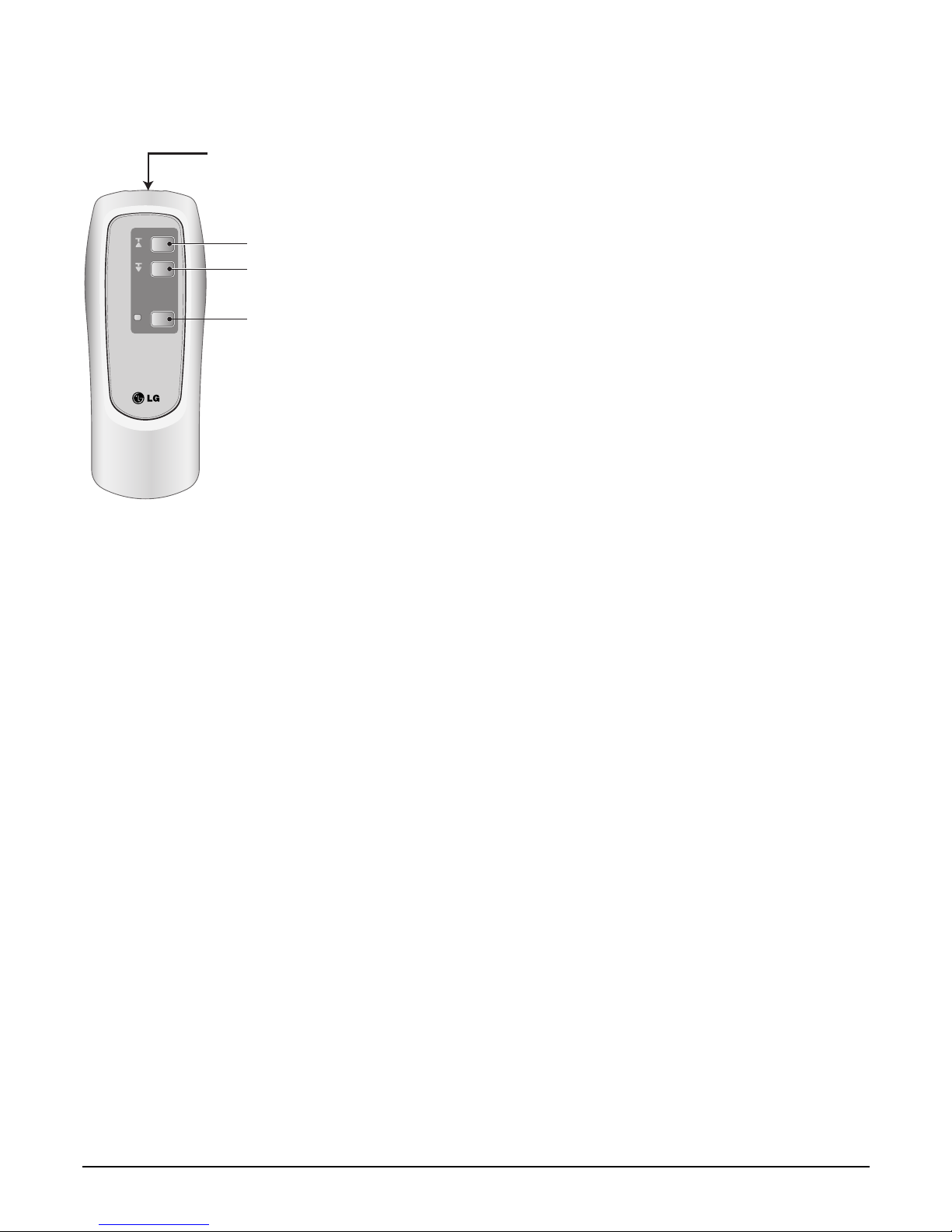
■ ELEVATION GRILL (REMOTE CONTROLLER_Accessory)
• How to Use Remote Controller
• Main Components of Lift Grill
As for operation of Remote Controller, use it by directing the transmitter part of Remote Controller to the receiver part of front panel
directly under front panel.
• Do not drop it down or into water. Or else there is worry about
trouble failure.
• Do not press hard the Remote Controller button with nail (ballpoint pen or other sharp substance). Or else there is worry
about trouble failure.
• In case when obstacle such as curtain hides the signal reception
part of receiver in between the space interval, Remote Controller
operation is infeasible.
➀ Lift grill front panel assembly
➁ Bolts for installation (4 EA, P/No. 3A00255K)
➂ Instruction manual
➃ Remote Controller for lift grill
Ascend
Signal transmitter
Descend
Stop
Page 6
- 6 -
Copyright ©2008 LG Electronics. Inc. All right reserved.
Only for training and service purposes
LGE Internal Use Only
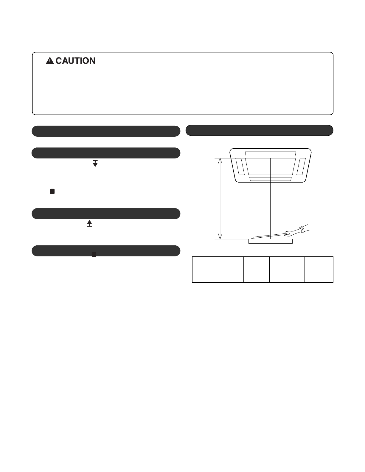
Automatic stop distance
✳
If you want to change automatic distance setting,
consult with your sale agency.
Automatic Stop Distance of Grill
Ceiling height Low
Medium
High
(
Height: 3~4 m)
Automatic stop distance
1.5±0.5 m 2.5±0.5 m 3.5±0.5 m
- Depress the down button( ).
Then suction grill descends and stops automatically at a certain
distance.
- You may stop it at wanted distance point by depressing the stop button ( ) when descending.
- Depress the up button( ).
Then suction grill goes up and enters into the front panel.
1. Stop the Air Conditioner Operation
2. Descend the Suction Grill
3. Raise the Suction Grill
- Depress the stop button( ).
Make use of this when you want to stop it at your wished position.
4. Stop the Suction Grill during Rising
• Always stop the air conditioner operation for safety before operating lift grill.
• Take heed _ there is worry about dust fall etc. when suction grill descends.
• In case when the set automatic stop distance goes wrong, check the set value of operation panel and con-
firm if there is neither obstacle nor mankind.
• When you are not to remove obstacle, stop the operation before touching the obstacle.
• How to Operate the Lift Grill
Page 7
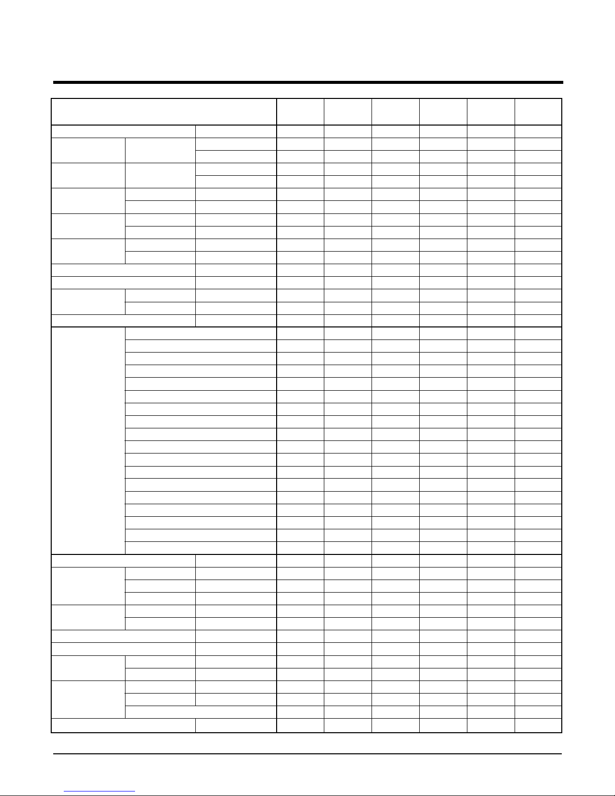
Model
1, 220-240, 50
4,536(5,274)
18,000
-
-
1,900
-
9.5
-
53
-
2.39
13
50
1.9
O
X
4
O
O
O
O
O
4
O
X
O
O
O
O
Optional
O
O
1,900
570 x 570 x 269
670 x 670 x 30
870 x 655 x 320
19(16.5+2.5)
60
14:3*2.5
18:4*0.75
1/4(6.35mm)
5/8(15.88mm)
50
30
FoamPE/5mm
ø25/32
1, 220-240, 50
4,536(5,274)
18,000
-
-
1,900
-
9.5
-
53
-
2.39
13
50
1.9
O
X
4
O
O
O
O
O
4
O
X
O
O
O
O
Optional
O
X
1,900
570 x 570 x 269
670 x 670 x 30
870 x 655 x 320
19(16.5+2.5)
60
14:3*2.5
18:4*0.75
1/4(6.35mm)
5/8(15.88mm)
50
30
FoamPE/5mm
ø25/32
1, 220-240, 50
4,536(5,274)
18,000
4,536(5,274)
18,000
2,050
1,850
9.5
9.0
53
53
2.21
2.85
13
50
1.9
O
O
4
O
O
O
O
O
4
O
O
O
O
O
O
Optional
O
X
1,800
570 x 570 x 269
670 x 670 x 30
870 x 655 x 320
19(16.5+2.5)
61
14:3*2.5
18:6*0.75
1/4(6.35mm)
5/8(15.88mm)
50
30
FoamPE/5mm
ø25/32
1, 220-240, 50
4,536(5,274)
18,000
4,536(5,274)
18,000
2,050
1,850
9.5
9.0
53
53
2.21
2.85
13
50
1.9
O
O
4
O
O
O
O
O
4
O
O
O
O
O
O
Optional
O
O
1,800
570 x 570 x 269
670 x 670 x 30
870 x 655 x 320
19(16.5+2.5)
61
14:3*2.5
18:6*0.75
1/4(6.35mm)
5/8(15.88mm)
50
30
FoamPE/5mm
ø25/32
1, 220, 60
4,536(5,274)
18,000
-
-
1,970
9
-
53
-
2.30
13
50
1.9
O
X
4
O
O
O
O
O
4
O
X
O
O
O
O
Optional
O
X
1,050
570 x 570 x 269
670 x 670 x 30
870 x 655 x 320
19
60
14:3*2.5
18:4*0.75
1/4(6.35mm)
5/8(15.88mm)
50
30
FoamPE/5mm
ø25/32
1, 220, 60
4,536(5,274)
18,000
4,536(5,274)
18,000
1,900
1,900
8.8
8.8
53
53
2.39
2.78
13
50
1.9
O
O
4
O
O
O
O
O
4
O
O
O
O
O
O
Optional
O
X
1,910
570 x 570 x 269
670 x 670 x 30
870 x 655 x 320
19
61
14:3*2.5
18:6*0.75
1/4(6.35mm)
5/8(15.88mm)
50
30
FoamPE/5mm
ø25/32
LT-E2460AA LT-E1860CL LT-E1860HL
LT-E1862HL
LT-E1862BA
LT-E1820CL
LT-C182ELE0
LT-E1820HL
LT-H182ELE0
Power Supply ø, V, Hz
Capacity Cooling kcal/h(W)
Btu/h
Heating kcal/h(W)
Btu/h
Input Cooling W
Heating W
Running Current Cooling A
Heating A
Starting Current Cooling A
Heating A
E.E.R kcal/h(W)
C.O.P W/W
Air Circulation Indoor m
3
/min
Outdoor m
3
/min
Moisture Removal l / h
Air-Flow Direction Control
Heating Operation Mode
Fan Speeds (steps)
Auto Operation (Changeover)
Forced Operation
Jet Cool
Soft Dry Operation
Timer Delay Safety Function
Feature Air Deflection (Way)
Self Diagnosis
Hot start
Auto Restart
Air refresh (Hole)
High Ceiling
Group Control (Optional wiring)
Central Control
Wired remote controller (with weekly Program)
Plasma A/Cleaner
Refrigerant(R-22) Charge g
Dimensions Indoor mm
(W x D x H) Panel mm
Outdoor mm
Net Weight Indoor kg
Outdoor kg
Main Power Cord AWG#:P*mm
2
Connection Cable AWG#:P*mm
2
Service Valve Liquid (inch)
Gas (inch)
Installation Pipe Length (m)
Elevation (m)
Insulation(material/thickness)
Drain Hose(I.D/O.D) mm
- 7 -
Copyright ©2008 LG Electronics. Inc. All right reserved.
Only for training and service purposes
LGE Internal Use Only
Product Specifications (Cooling & Heating)
Page 8
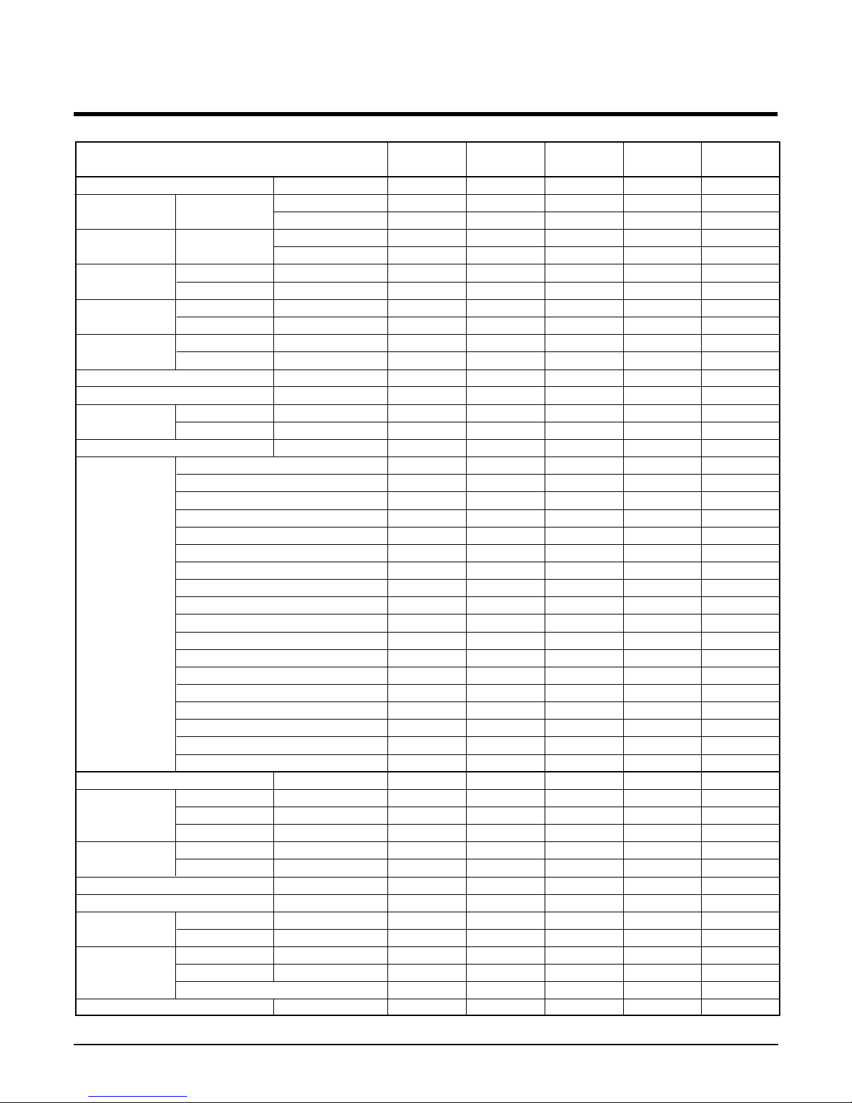
- 8 -
Copyright ©2008 LG Electronics. Inc. All right reserved.
Only for training and service purposes
LGE Internal Use Only
Power Supply ø, V, Hz
Capacity Cooling kcal/h(W)
Btu/h
Heating kcal/h(W)
Btu/h
Input Cooling W
Heating W
Running Current Cooling A
Heating A
Starting Current Cooling A
Heating A
E.E.R kcal/h(W)
C.O.P W/W
Air Circulation Indoor m
3
/min
Outdoor m
3
/min
Moisture Removal l / h
Air-Flow Direction Control
Heating Operation Mode
Fan Speeds (steps)
Auto Operation (Changeover)
Forced Operation
Jet Cool
Soft Dry Operation
Timer Delay Safety Function
Feature Air Deflection (Way)
Self Diagnosis
Hot start
Auto Restart
Air refresh (Hole)
High Ceiling
Group Control (Optional wiring)
Central Control
Wired remote controller (with weekly Program)
Plasma A/Cleaner
Refrigerant(R-22) Charge g
Dimensions Indoor mm
(W x D x H) Panel mm
Outdoor mm
Net Weight Indoor kg
Outdoor kg
Main Power Cord AWG#:P*mm
2
Connection Cable AWG#:P*mm
2
Service Valve Liquid (inch)
Gas (inch)
Installation Pipe Length (m)
Elevation (m)
Insulation(material/thickness)
Drain Hose(I.D/O.D) mm
Model
LT-E2460CL
LT-C246ELE0
LT-E2460HL LT-E2460BL
LT-E2462HL/BL
LT-H246ELE0/ELF0
LT-E2462CL
LT-E2460AA
1, 220-240, 50
5,871(6,827)
23,300
-
-
2,600
-
13.5
-
62
-
2.26
-
15.5
50
2.9
O
X
4
O
O
O
O
O
4
O
X
O
O
O
O
Optional
O
X
1,900
570 x 570 x 269
670 x 670 x 30
870 x 655 x 320
19(16.5+2.5)
61
14:3*2.5
18:4*0.75
1/4(6.35mm)
5/8(15.88mm)
50
30
FoamPE/5mm
ø25/32
1, 220-240, 50
5,871(6,827)
23,300
5,922(6,886)
23,500
2,600
2,600
13.5
13.5
62
60
2.26
2.65
15.5
50
2.9
O
O
4
O
O
O
O
O
4
O
O
O
O
O
O
Optional
O
X
1,900
570 x 570 x 269
670 x 670 x 30
870 x 655 x 320
19(16.5+2.5)
62
14:3*2.5
18:6*0.75
1/4(6.35mm)
5/8(15.88mm)
50
30
FoamPE/5mm
ø25/32
1, 220-240, 50
5,871(6,827)
23,300
5,922(6,886)
23,500
2,600
2,600
13.5
13.5
62
60
2.26
2.65
15.5
50
2.9
O
O
4
O
O
O
O
O
4
O
O
O
O
O
O
Optional
O
X
1,900
570 x 570 x 269
670 x 670 x 30
870 x 655 x 320
19(16.5+2.5)
62
14:3*2.5
18:6*0.75
1/4(6.35mm)
5/8(15.88mm)
50
30
FoamPE/5mm
ø25/32
1, 220-240, 50
5,871(6,827)
23,300
5,922(6,886)
23,500
2,600
2,600
13.5
13.5
62
60
2.26
2.65
15.5
50
2.9
O
O
4
O
O
O
O
O
4
O
O
O
O
O
O
Optional
O
O
1,900
570 x 570 x 269
670 x 670 x 30
870 x 655 x 320
19(16.5+2.5)
62
14:3*2.5
18:6*0.75
1/4(6.35mm)
5/8(15.88mm)
50
30
FoamPE/5mm
ø25/32
1, 220-240, 50
5,871(6,827)
23,300
-
-
2,600
-
13.5
-
62
-
2.26
-
15.5
50
2.9
O
X
4
O
O
O
O
O
4
O
X
O
O
O
O
Optional
O
O
1,900
570 x 570 x 269
670 x 670 x 30
870 x 655 x 320
19(16.5+2.5)
61
14:3*2.5
18:6*0.75
1/4(6.35mm)
5/8(15.88mm)
50
30
FoamPE/5mm
ø25/32
Page 9
- 9 -
Copyright ©2008 LG Electronics. Inc. All right reserved.
Only for training and service purposes
LGE Internal Use Only
Dimensions
269
67055
570
269
190.5
160
52
90
90
120.4
30
521
670
570
450
40
110 110
670
670
CLOSE OPEN OPEN CLOSE
(1) Indoor Unit
Page 10
- 10 -
Copyright ©2008 LG Electronics. Inc. All right reserved.
Only for training and service purposes
LGE Internal Use Only
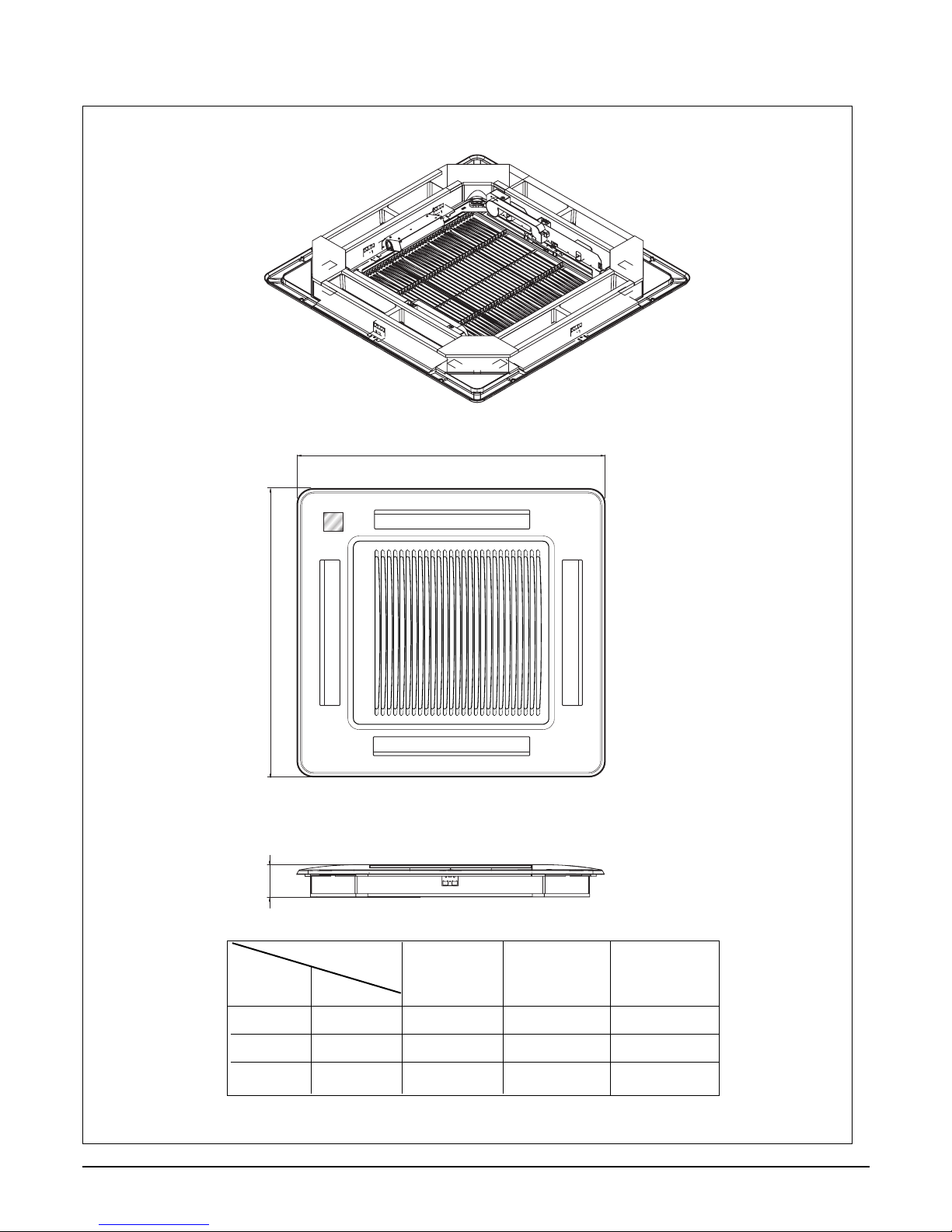
LT-H***ELE0
LT-H***FLE0
LT-H***DLE0
W
D
H
W mm 670 850 950
Hmm909090
D mm 670 850 950
(unit : mm)
Model
LT-H***ELE0 LT-H***FLE0 LT-H***DLE0
DIM
Unit
Page 11
- 11 -
Copyright ©2008 LG Electronics. Inc. All right reserved.
Only for training and service purposes
LGE Internal Use Only
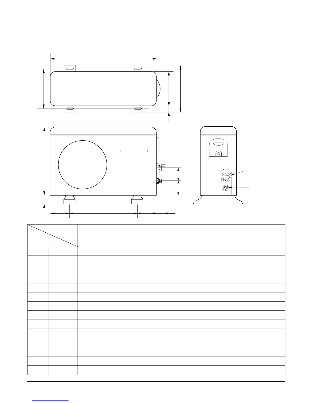
(2) Outdoor Unit
Gas side
3-way valve
Liquid side
3-way valve
W
L6L7 L8 L9
L4
L11
L10
D
L1
L2
L5
L3
MODEL
DIM
W mm 870
H mm 655
D mm 320
L1 mm 370
L2 mm 25
L3 mm 340
L4 mm 630
L5 mm 25
L6 mm 546
L7 mm 162
L8 mm 162
L9 mm 54
L10 mm 74.5
L11 mm 79
All Models
Page 12
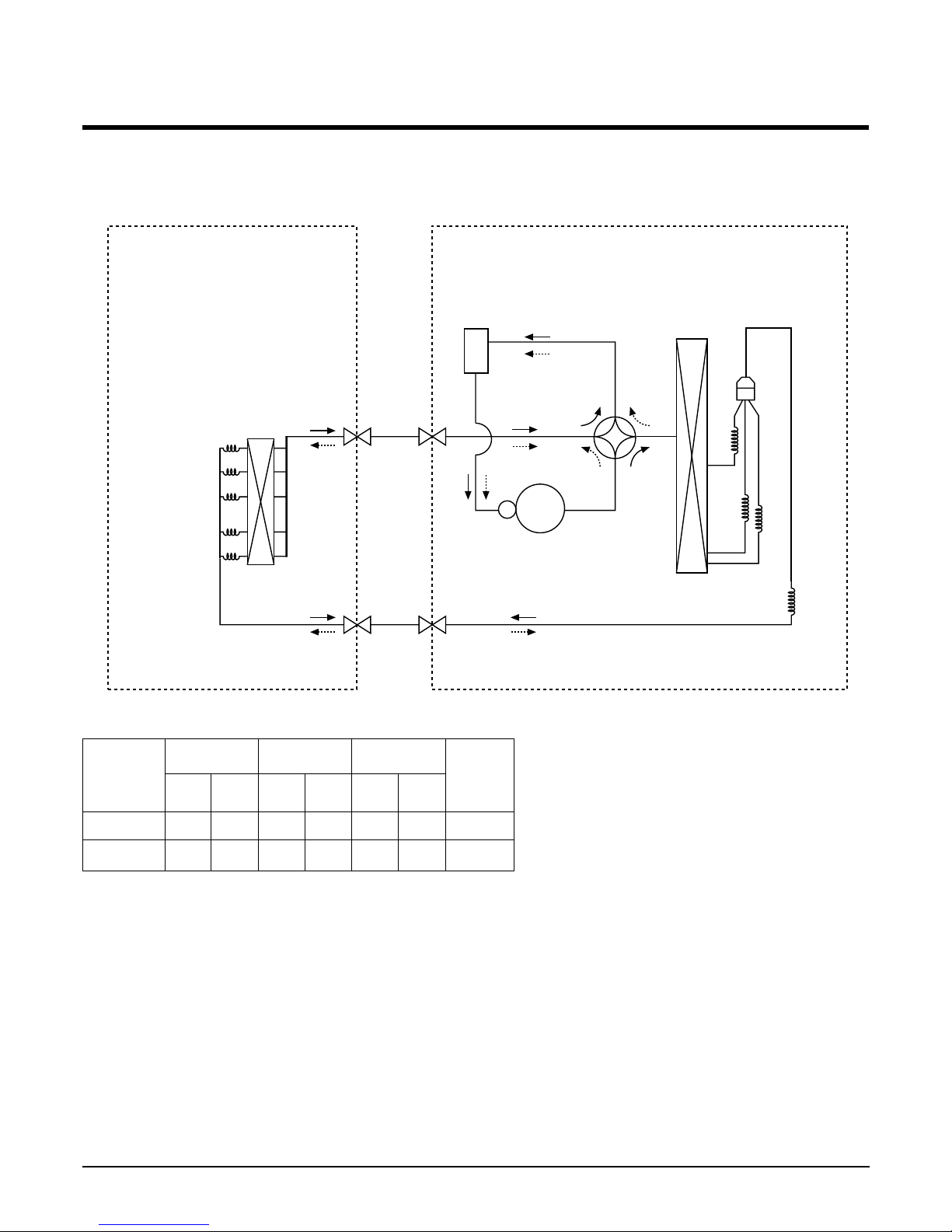
Refrigeration Cycle Diagram
• HEAT PUMP
• Rated performance for refrigerant line length of: 7.5m
• If 18K Capacity is installed at a distance of 15m, 187.5g of refrigerant
should be added ....................................................(15-7.5)x25g
- 12 -
Copyright ©2008 LG Electronics. Inc. All right reserved.
Only for training and service purposes
LGE Internal Use Only
INDOOR UNIT
H/EX
Liquid SideGas Side
COMPRESSOR
VALVE REVERSING
ACCUM.
H/EX
Gas SideLiquid Side
CAPI C1
CAPI A
CAPI B
Heating Cooring
CAPI C2
(
OUTDOOR UNIT
GAS LIQUID
Elevation (m)
Length (m)
* Additional
refrigerant
(g/m)
Pipe Size
Rated Rated
Max. Max.
Capacity
18K 5/8" 1/4"
7.
5 50 5 30 25
24K 5/8" 1/4"
7.5 50 5 30 30
Page 13
- 13 -
Copyright ©2008 LG Electronics. Inc. All right reserved.
Only for training and service purposes
LGE Internal Use Only
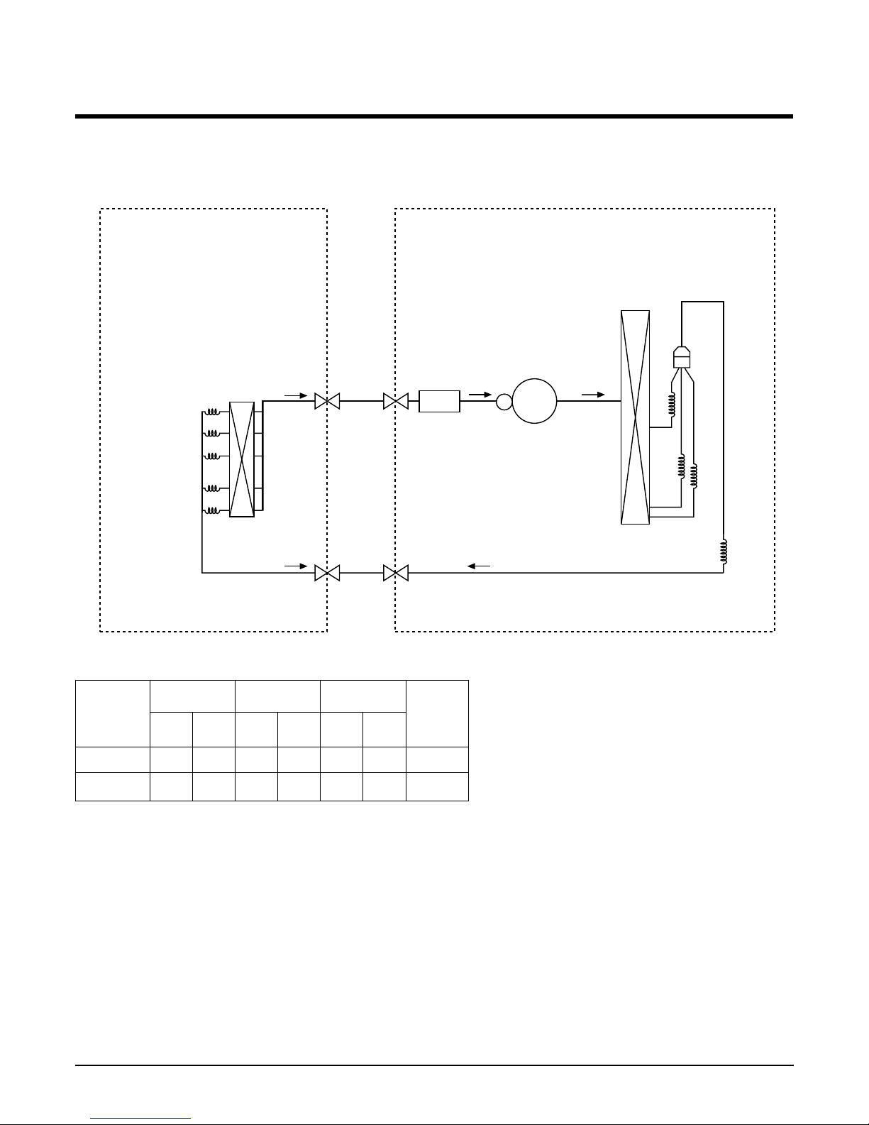
• COOLING ONLY
• Rated performance for refrigerant line length of: 7.5m
• If 18K Capacity is installed at a distance of 15m, 187.5g of refrigerant
should be added ....................................................(15-7.5)x25g
INDOOR UNIT
H/EX
Liquid SideLiquid Side
COMPRESSOR
ACCUM.
H/EX
Gas SideGas Side
CAPI C1
CAPI A
CAPI B
CAPI C2
OUTDOOR UNIT
GAS LIQUID
Elevation (m)
Length (m)
* Additional
refrigerant
(g/m)
Pipe Size
Rated Rated
Max. Max.
Capacity
18K 5/8" 1/4" 7.5 50 5 30 25
24K 5/8" 1/4" 7.5 50 5 30 30
Page 14
- 14 -
Copyright ©2008 LG Electronics. Inc. All right reserved.
Only for training and service purposes
LGE Internal Use Only
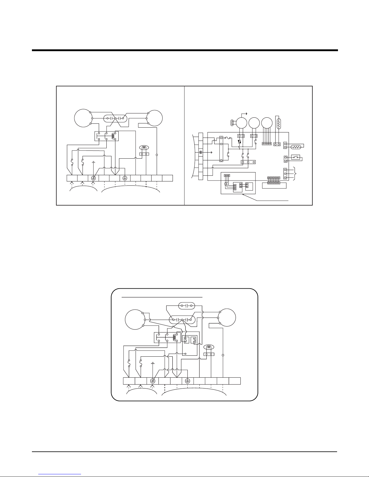
Wiring Diagram
• HEAT PUMP
Model No.: LT-E1862HL/ LT-E1862BA/ LT-E2462HL
LT-E2462BA/ LT-E2460BL/ LT-H182ELEO/LT-H246ELE0/LT-H246ELF0
LT-E2460HL(Australia only)
OUTDOOR WIRING DIAGRAM INDOOR WIRING DIAGRAM
COMP
R
S
H
42861
0
CF
BL
YL
OR
BK
TB2
BR
BR
BR
BR
BL
BL
BL
BL
BL
GN/YL
GN/YL
BK
BK
RD
CAPACITOR
REVERSING
VALVE
RD
C
POWER
RELAY
FAN
MOTOR
FUSE 5A
FUSE 5A
POWER
INPUT
TO INDOOR UNIT
TERMINAL
BLOCK
1(L)2(N
)
3(L)4(N
)
5
6
7
8
INDOOR
MOTOR
DRAIN
PUMP
STEP
MOTOR
TEMP.
THERMISTOR
PIPE
THERMISTOR
REMOTE
CONTROL
FLOAT S/W
CN - DISP
DISPLAY PCB
Only for LT-Exxx2HL
AIR
CLEANER
H.V. ASSY
DOOR S/W
TERMINAL
BLOCK
TO OUTDOOR UNIT
BR
YL
BK
OR
BL
BL
BR
GN/YL
RD
BK
YL
BL
GN
/
YL
OUT FAN
COMP
4 WAY
RD
BK
WH
RD
BK
3
(
L
)
4
(
N
)
5 6 7
FUSE T3.15A
OUTDOOR WIRING DIAGRAM
COMP
R
S
H
42861
0
CF
BL
YL
YL
WH
YL
OR
BK
TB2
BR
BR
BR
BR
BL
BL
BL
BL
BL
BL
GN/YL
GN/YL
BK
BK
RD
CAPACITOR
S/CAPACITOR
REVERSING
VALVE
RD
C
POWER
RELAY
FAN
MOTOR
FUSE 5A
FUSE 5A
POWER
INPUT
TO INDOOR UNIT
TERMINAL
BLOCK
3854A20119A
1(L)2(N
)
3(L)4(N
)
5
6
7
8
3
RYCOMP
RYS/CAPA
CN-POWER
434
Page 15
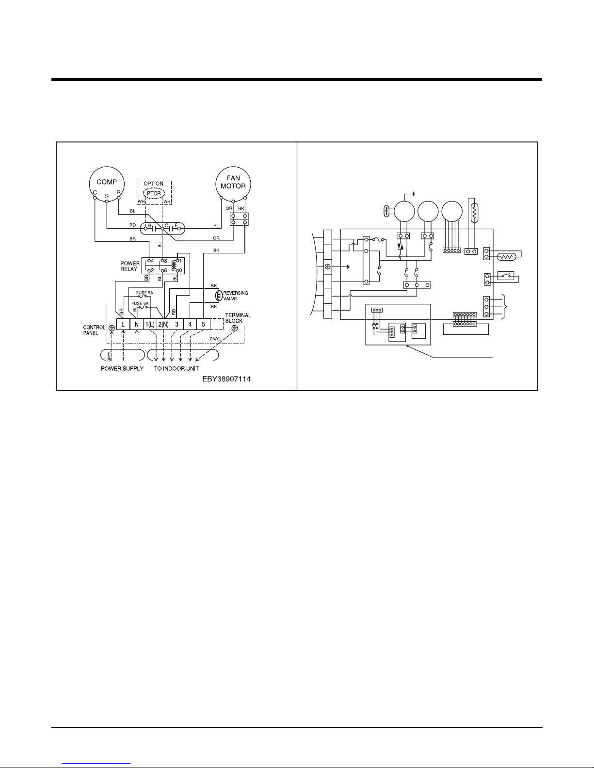
• HEAT PUMP
Model No.: LT-E1860HL/ LT-E2460HL/
- 15 -
Copyright ©2008 LG Electronics. Inc. All right reserved.
Only for training and service purposes
LGE Internal Use Only
OUTDOOR WIRING DIAGRAM INDOOR WIRING DIAGRAM
INDOOR
MOTOR
DRAIN
PUMP
STEP
MOTOR
TEMP.
THERMISTOR
PIPE
THERMISTOR
REMOTE
CONTROL
FLOAT S/W
CN - DISP
DISPLAY PCB
Only for LT-Exxx2HL
AIR
CLEANER
H.V. ASSY
DOOR S/W
TERMINAL
BLOCK
TO OUTDOOR UNIT
BR
YL
BK
OR
BL
BL
BR
GN/YL
RD
BK
YL
BL
GN
/
YL
OUT FAN
COMP
4 WAY
RD
BK
WH
RD
BK
3
(
L
)
4
(
N
)
5 6 7
FUSE T3.15A
Page 16
- 16 -
Copyright ©2008 LG Electronics. Inc. All right reserved.
Only for training and service purposes
LGE Internal Use Only
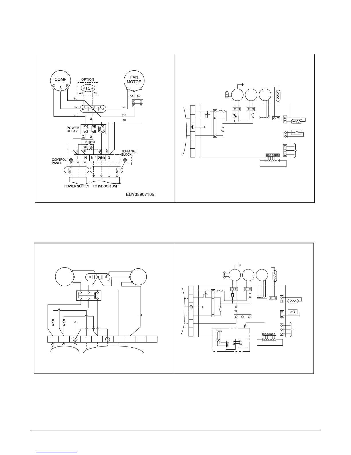
• COOLING ONLY
Model No.: LT-E1860CL/LT-E1860AA/LT-C182ELE0
Model No.: LT-E2460CL/LT-E2462CL/LT-E2460AA/LT-C246ELE0
OUTDOOR WIRING DIAGRAM INDOOR WIRING DIAGRAM
INDOOR
MOTOR
DRAIN
PUMP
STEP
MOTOR
TEMP.
THERMISTOR
PIPE
THERMISTOR
REMOTE
CONTROL
FLOAT S/W
CN - DISP
DISPLAY PCB
TERMINAL
BLOCK
TO OUTDOOR UNIT
BR
YL
BK
OR
BL
BL
BR
GN/YL
RD
BL
GN
/
YL
COMP
3
(
L
)
4
(
N
)
5 6 7
FUSE T3.15A
OUTDOOR WIRING DIAGRAM INDOOR WIRING DIAGRAM
INDOOR
MOTOR
DRAIN
PUMP
STEP
MOTOR
TEMP.
THERMISTOR
PIPE
THERMISTOR
REMOTE
CONTROL
FLOAT S/W
CN - DISP
DISPLAY PCB
LT-E
***
2
HL ONLY
AIR
CLEANER
H.V. ASSY
DOOR S/W
TERMINAL
BLOCK
TO OUTDOOR UNIT
BR
YL
BK
OR
BL
BL
BR
GN/YL
RD
YL
BL
GN
/
YL
COMP
RD
BK
WH
RD
BK
3(L) 4(N)
5 6 7
FUSE T3.15A
OUT FAN
COMP
R
S
H
42861
0
CF
BL
YL
OR
BK
TB2
BR
BR
BR
BR
BL
BL
BL
BL
BL
GN/YL
GN/YL
BK
RD
CAPACITOR
RD
C
POWER
RELAY
FAN
MOTOR
FUSE 5A
FUSE 5A
POWER
INPUT
TO INDOOR UNIT
TERMINAL
BLOCK
1(L)2(N
)
3(L)4(N
)
5
6
7
8
Page 17
- 17 -
Copyright ©2008 LG Electronics. Inc. All right reserved.
Only for training and service purposes
LGE Internal Use Only
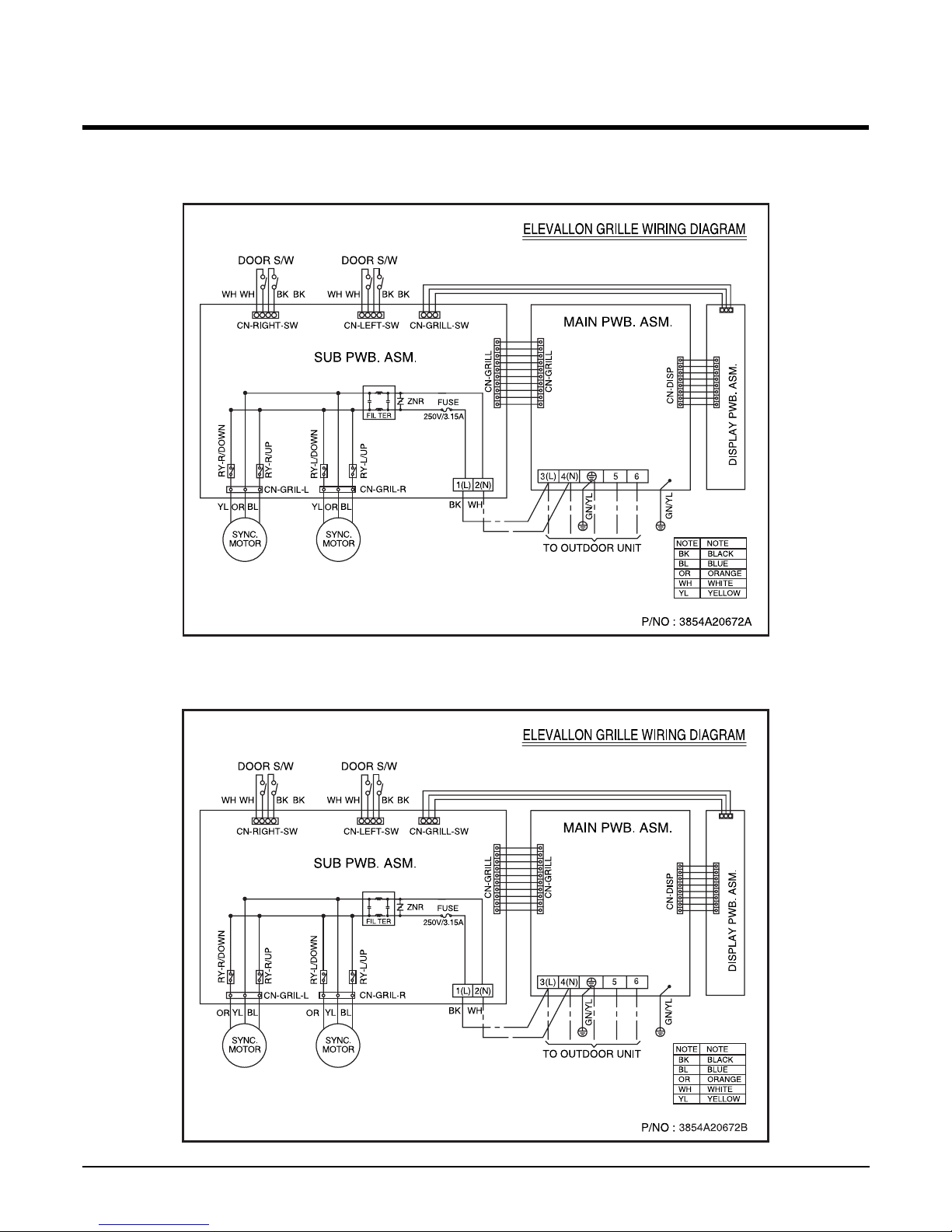
■ ELEVATION GRILL WIRING DIAGRAM (INDOOR)
LT-H***DLE0/LT-C***DLE0
LT-H***ELE0/LT-C***ELE0
LT-H***FLE0/LT-C***FLE0
Page 18
- 18 -
Copyright ©2008 LG Electronics. Inc. All right reserved.
Only for training and service purposes
LGE Internal Use Only
Operation Details
(1) The function of main control
1. Time Delay Safety Control
• 3min The compressor is ceased for 3minutes to balance the pressure in the refrigeration cycle.
(Protection of compressor)
• 5sec
Vertical air flow direction control louvers open in 5 seconds to prevent noise between louvers and wind.
• 30sec The 4-way valve is ceased for 30sec. to prevent the refrigerant-gas abnormal noise when the Heating
operation is OFF or switched to the other operation mode while compress is off.
While compressor is running, it takes 3~5 seconds to switch.
2. Auto Swing Control
• This function is to swing the louver up and down automatically.
3. Air-Filter Checking Control
• 'Filter' will display in the remote controller display and main body display when an air-filter is polluted. Then clean
the air-filter for reference to Owners Manual.
4. Soft-Dry Operation
• The indoor fan speed is automatically set to the low, so the shift of the indoor fan speed is impossible because of
already being set to the best speed for Dry Operation by Micom Control.
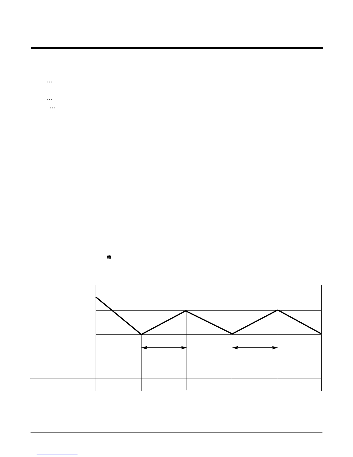
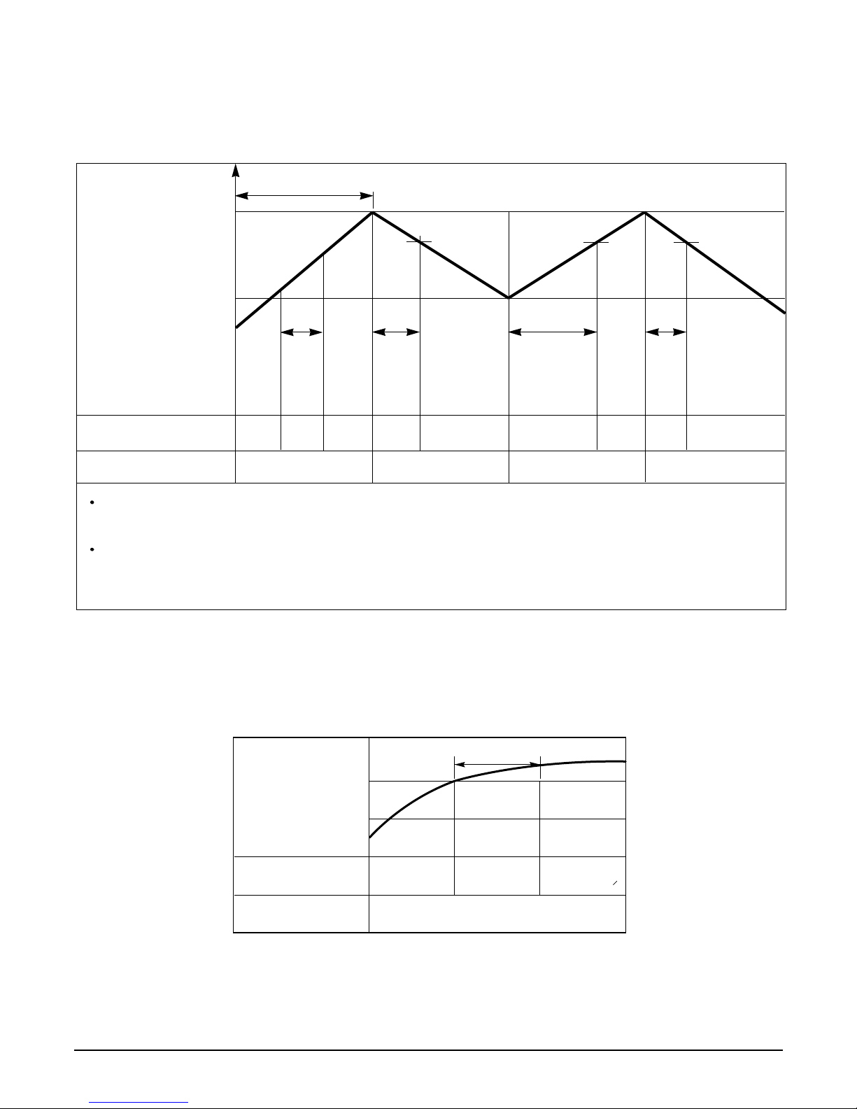
5. Cooling Mode Operation
• When selecting the Cooling( ) Mode Operation, the unit will operate according to the setting by the remote con-
troller and the operation diagram is as following
Intake Air temp.
SET TEMP.+0.5°C
(COMP. ON)
SET TEMP. -0.5°C
(COMP. OFF) More than More than
3 minutes 3 minutes
Selecting Selecting Selecting
fan speed fan speed fan speed
COMPRESSOR ON OFF ON OFF ON
INDOOR FAN Low Low
Page 19
- 19 -
Copyright ©2008 LG Electronics. Inc. All right reserved.
Only for training and service purposes
LGE Internal Use Only
Intake Air temp.
Setting temp.+3°C
(Compressor OFF)
Setting temp.
(Compressor ON)
INDOOR FAN
COMPRESSOR ON OFF ON OFF
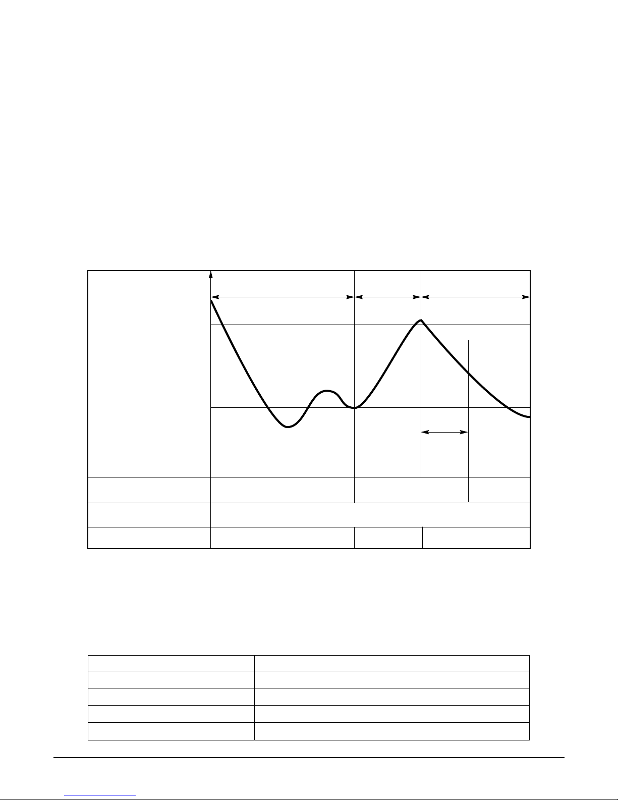
A point; While the indoor Heat-Exchanger temperature is higher than 40°C fan operates at low speed, when
it becomes lower than 40˚C fan stops.
B point; When the indoor Heat-Exchanger temperature is higher than 42°C, fan operates at selected fan
speed, when it becomes lower than 39°C, the fan operates at low speed.
6. Heating Mode Operation
The unit will operate according to the setting by the remote controller and the operation diagram is shown as follows.
(Hot Start)
Low
OFF
Selected
Fan Speed
minimum 3min
Selecting fan
speed
LowLowLow OFF OFF
minimum
10sec.
1min
A
A
minimum
1min.
minimum
10sec.
B
7. Hot-Start Control
• The indoor fan stops until the evaporator piping temperature reaches to 25°C.
• If the evaporator piping temperature drops below 22°C, indoor fan stops again.
• The operation diagram is as follows.
PIPING
TEMPERATURE
1min
COMPRESSOR
INDOOR FAN
ON
OFF LOW
Selected
fan speed
22°C
25°C
Page 20
- 20 -
Copyright ©2008 LG Electronics. Inc. All right reserved.
Only for training and service purposes
LGE Internal Use Only
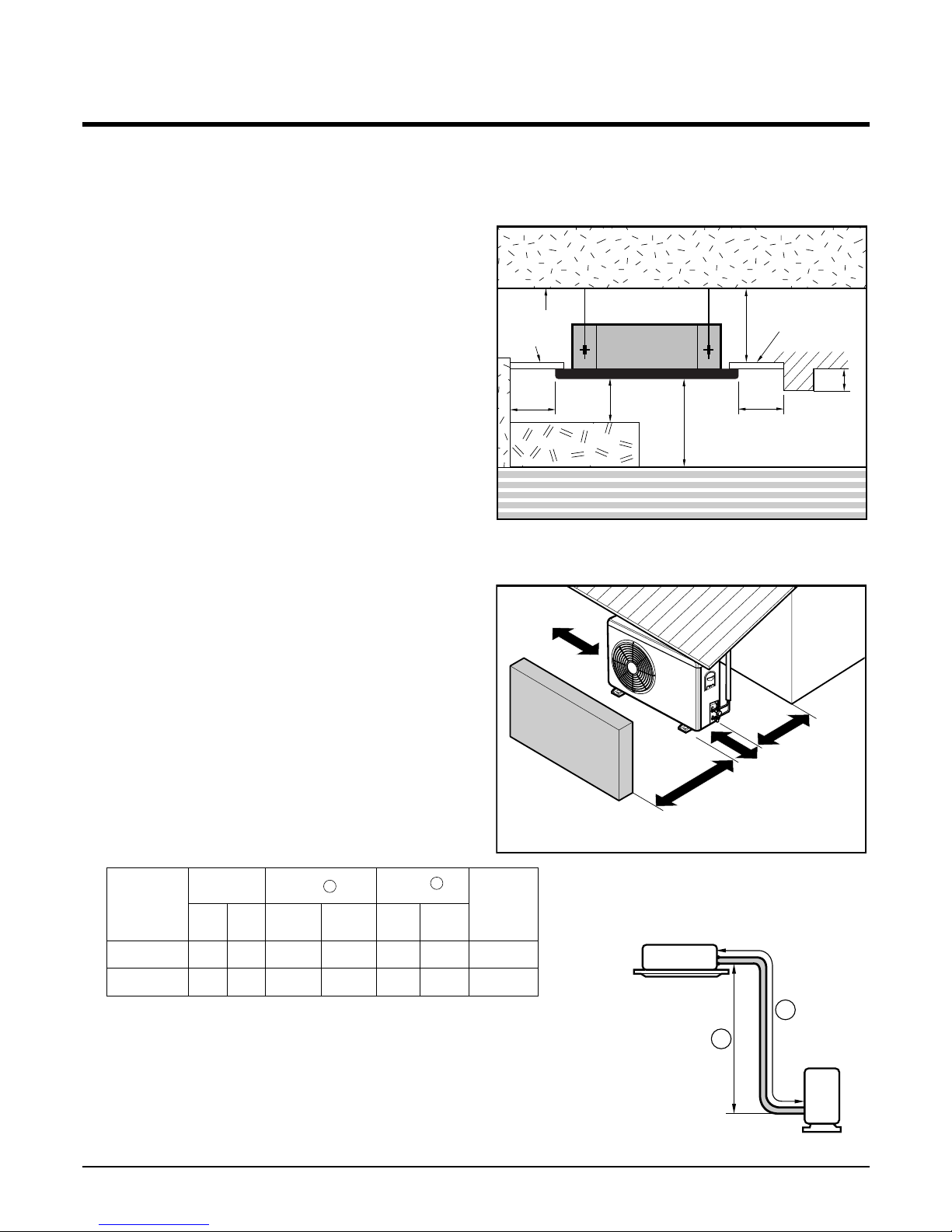
8. Defrost Control (18k, 24k)
• While in heating mode operation in order to protect the evaporator pipe of the outdoor unit from freezing, reversed to
cooling cycle to defrost the evaporator pipe of the outdoor unit.
• Defrost control is available 45 min. later since heating mode operation started, and it will not prolong over 10 min.
• Defrost control is carried out according to the following priority order while in heating mode operation.
1st priority : Defrost control is carried out according to the indoor pipe temp 60 min. later since heating mode opera-
tion started.
2nd priority : The temp differences between the indoor pipe temp and the intake air temp 25 min. later(∆T1) and 45
min. later (∆T2) since heating mode operation started are measured, then defrost control is carried out
according to the dirrerence (∆T=∆T1-∆T2)
3rd priority : Defrost control is carried out according to the temp difference (E=TE1-TE2) between the indoor pipe
temperatures of 25 min later(TE1) and 45 min later (TE2) after heating mode operation started.
• When the indoor pipe temp is 41°C or above, defrost control is not carried out even if the condition is one of the
defrost conditions above.
• While in defrost control, the compressor is on and the indoor fan, the outdoor fan, and the 4 way valve are off.
9. Self-diagnosis Function
• 'CHECK' will flash in the remote controller display when a problem occurs.
• Correct the (fault messages) as shown in the table below before restarting operation.
• During the normal operation 'CHECK' won't be displayed in the remote controller.
Remote controller LCD FAULT MESSAGES
CH 01 Indoor room temperature thermistor error
CH 02 Indoor piping thermistor error
CH 03
Indoor main body / Remote controller unit communication error
CH 04 Water level float switch error
More than 45 minutes
of heating operation
Within
9min. 45sec.
ON OFF
ON
ON
ON OFF
COMPRESSOR
4-WAY VALVE
INDOOR FAN
-6°C ON
12°C OFF
The outdoor
piping Temp.
More than 10 min.
running of compressor
More than 45 minutes
of heating operation
HOT-
START
ON
Page 21
- 21 -
Copyright ©2008 LG Electronics. Inc. All right reserved.
Only for training and service purposes
LGE Internal Use Only
Installation of Indoor, Outdoor Unit
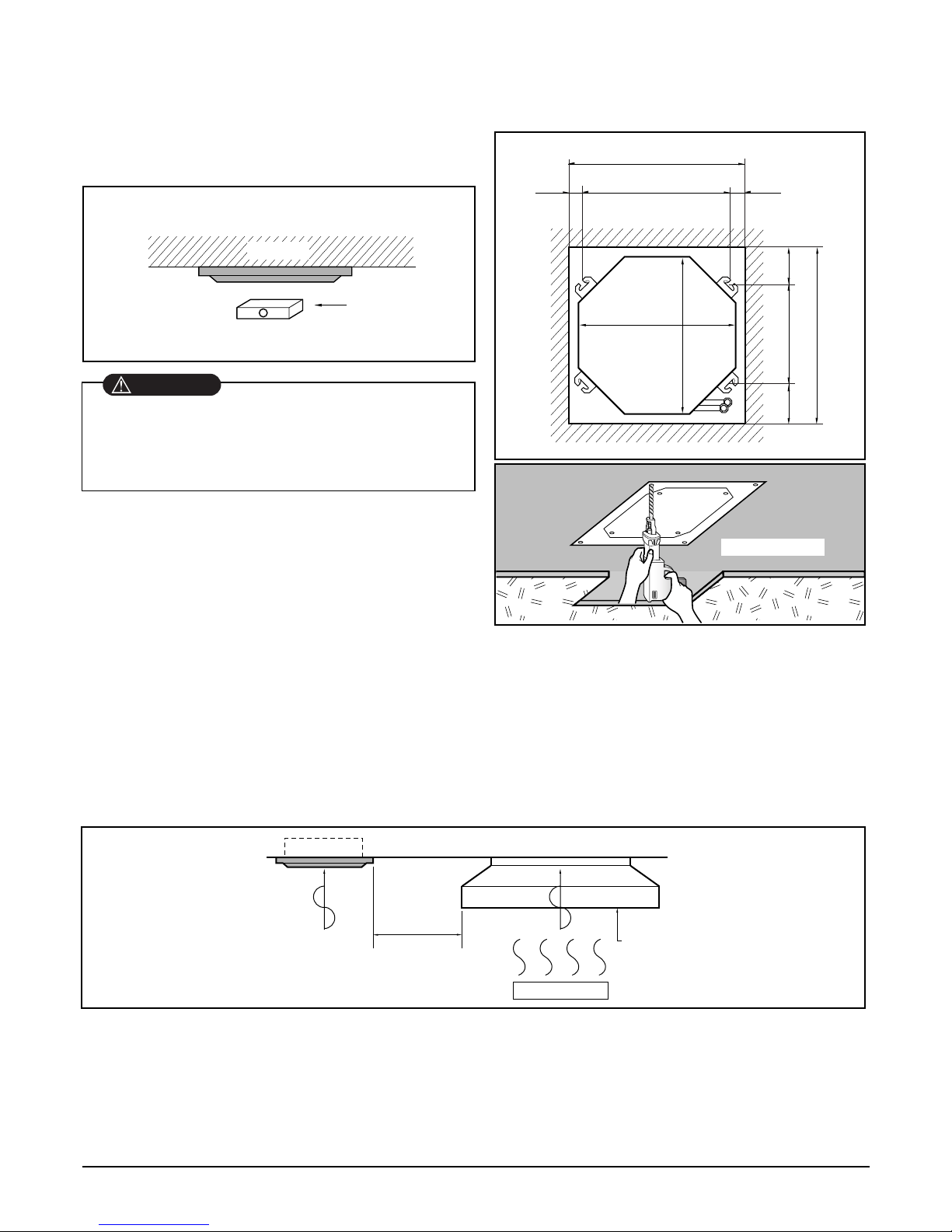
1. Selection of the best location
1) Indoor unit
• There should not be any heat source or steam
near the unit.
• There should not be any obstacles to the air circulation.
• A place where air circulation in the room will be
good.
• A place where drainage can be easily obtained.
• A place where noise prevention is taken into con-
sideration.
• Do not install the unit near the door way.
• Ensure the spaces indicated by arrows from the
wall, ceiling, or other obstacles.
• The indoor unit must have the maintenance
space around.
2) Outdoor unit
• If an awning is built over the unit to prevent direct
sunlight or rain exposure, be careful that heat
radiation from the condenser is not restricted.
• There should not be any animals or plants which
could be affected by hot air discharged.
• Ensure the spaces indicated by arrows from the
wall, ceiling, fence or other obstacles.
3) Piping length and the elevation
More than
30cm
Sunroof
Fence or
obstacles
More than 70cm
More than 50cm
More than
30cm
More than
30cm
Indoor unit
Outdoor unit
B
A
Unit:cm
Ceiling
Ceiling Board
Ceiling Board
30 or more
Above 250
330 or less
100
or more
50 or
more
50 or
more
30 or less
Floor
• Rated performance for refrigerant piping length: 7.5m
• If 18K Model is installed at a distance of 15m, 187.5g of
refrigerant should be added (15-7.5)x25g
18K Btu/h
5/8" 1/4"
7.
5 50 5 30 25
24
K Btu/h
5/8" 1/4"
7.
5 50 5 30 30
CAPACITY
GAS LIQUID
Elevation B (m)
Length A (m)
* Additional
refrigerant
(g/m)
Pipe Size
Rated Rated
Max. Max.
Page 22
- 22 -
Copyright ©2008 LG Electronics. Inc. All right reserved.
Only for training and service purposes
LGE Internal Use Only
NOTE:
• Avoid the following installation location.
1. Such places as restaurants and kitchen where considerable amount of oil steam and flour is generated.
These may cause heat exchange efficiency reduction, or water drops, drain pump mal-function.
In these cases, take the following actions;
• Make sure that ventilation fan is enough to cover all noxious gases from this place.
• Ensure enough distance from the cooking room to install the air conditioner in such a place where it may
not suck oily steam.
2. Avoid installng air conditioner in such places where cooking oil or iron powder is generated.
3. Avoid places where inflammable gas is generated.
4. Avoid place where noxious gas is generated.
5. Avoid places near high frequency generators.
2. Ceiling opening dimensions and hanging bolt location
Unit:mm
570 Unit size
570 Unit size
450 (Hanging bolt)
7575
600 (Ceiling opening)
600 (Ceiling opening)
521(Hanging bolt)
39.5
39.5
Ceiling board
Level gauge
Ceiling
Use the ventilation fan
for smoke-collecting
hood with sufficient
capacity.
Cooking table
Air conditioner
Take enough
distance
• The dimensions of cardboard for installing are the
same as those of the ceiling opening dimensions.
• Select and mark the position for fixing bolts and piping hole.
• Decide the position for fixing bolts slightly tilted to the drain
direction after considering the direction of drain hose.
• Drill the hole for anchor bolt on the wall.
• This air-conditioner uses a drain pump.
• Install the unit horizontally using a level gauge.
• During the installation, be careful not to damage
electric wires.
CAUTION
Page 23
- 23 -
Copyright ©2008 LG Electronics. Inc. All right reserved.
Only for training and service purposes
LGE Internal Use Only
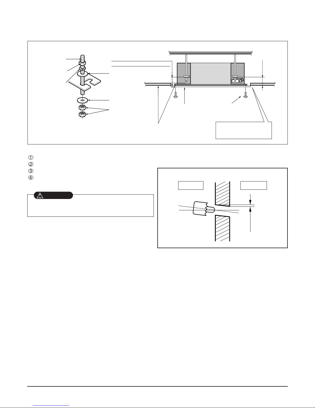
Wall
5~7mm
Indoor Outdoor
Set screw of
cardboard (4 pieces)
Cardboard
for installation
Ceiling board
150mm
Adjust the same height
Ceiling board
Ceiling
Flat washer for M10
(accessory)
Keep the length of the bolt
from the bracket to 40mm
Open the ceiling board
along the outer edge of the
paper model
Flat washer for M10
(accessory)
Hanging bolt
(W3/8 or M10)
Nut
(W3/8 or M10)
Nut
(W3/8 or M10)
Spring washer
(M10)
Air Conditioner body
3. The Indoor Unit Installation
• The following parts are local purchasing.
Hanging Bolt - W 3/8 or M10
Nut - W 3/8 or M10
Spring Washer - M10
Plate Washer - M10
• Drill the piping hole on the wall slightly tilted to the
outdoor side using a Ø 70 hole-core drill.
• Tighten the nut and bolt to prevent the unit from
falling off.
CAUTION
4. Remote Controller Installation
• Although the room temperature sensor is in the indoor unit, the remote controller should be installed
in such places away from direct sunlight and high humidity.
Installation of the remote controller
• Select places that are not splashed with water.
• Select control position after discussion with customer.
• The room temperature sensor is built in the indoor unit.
• This remote controller is equipped with liquid crystal display. If this position is higher or lower, display is diffi-
cult to see.(The standard height is 1.2 ~ 1.5m high)
Routing of the remote controller cord
• Keep the remote controller cord away from the refrigerant piping and the drain piping.
• To protect the remote controller cord from electrical noise, place the cord at least 5cm away from other power
cables (audio equipment, television set, etc.)
• If the remote controller cord is secured to the wall, provide a trap at the top of the cord to prevent water
droplets from running to the controller.
Page 24
- 24 -
Copyright ©2008 LG Electronics. Inc. All right reserved.
Only for training and service purposes
LGE Internal Use Only
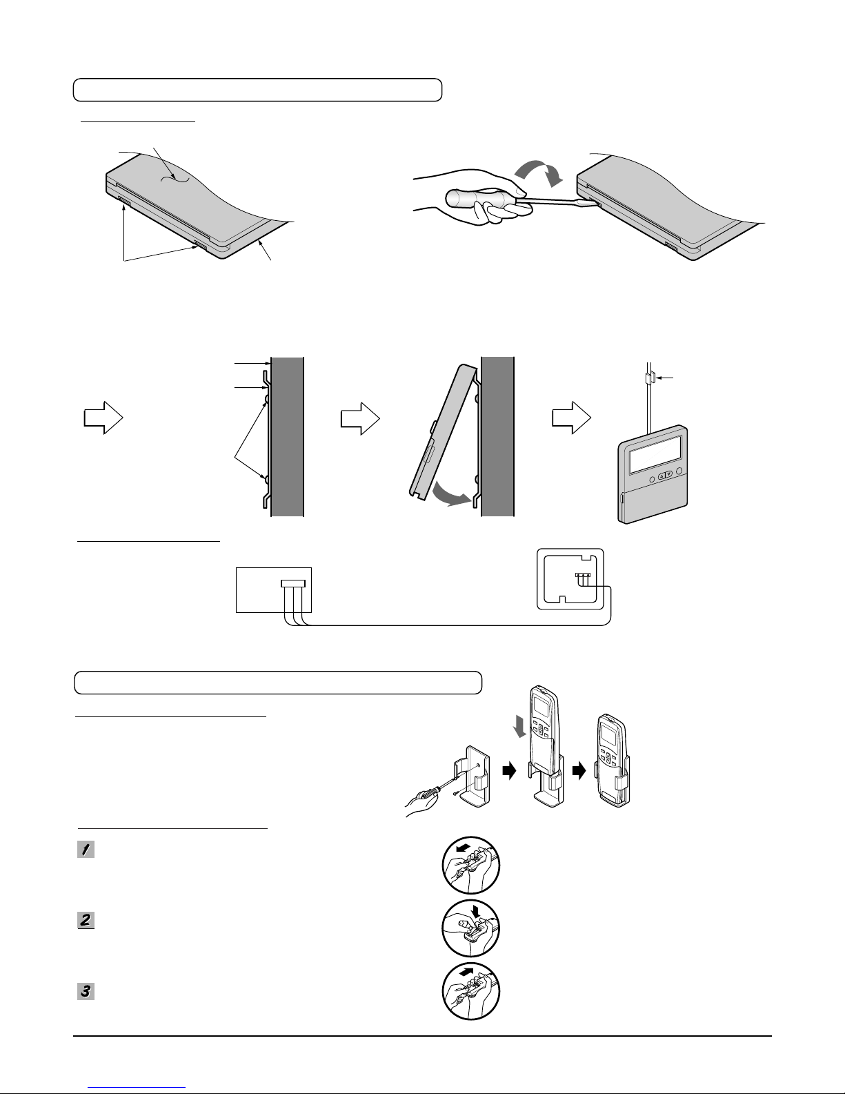
• Fix the under plate on the wall
• Separate the under plate from Remote control box.
• Fix the cord clamps on the wall by ø 3 tapping
screws (accessory).
• Fix the remote control cord.
Remote control
box body
Cord clamp
(accessory)
Lever carefully
the box open
using a screw
driver, etc.
Front case
The lower part
Face of wall
Under plate
Screw (accessory)
Remove the battery cover from the remote controller.
•
Pull out the cover according to the arrow direction.
Insert the two batteries.
• Be sure that the (+) and (-) directions are correct.
• Be sure that both batteries are new.
Re-attach the cover.
• Slide it back into position.
WIRED REMOTE CONTROL INSTALLATION
REMOTE CONTROL PREPARATION(OPTIONAL)
DISASSEMBLING
ELECTRICAL WIRING
HO
W TO MOUNT ON A WALL
HOW TO INSERT BATTERIES
Make sure that wire and teminal
numbers are matched on unit side and
remote controller side.
The maximum length of the cord is 100m.
If the length of the cord exceeds 50m,
use a wire size greater than 0.5mm
2
.
Remote controller
(Main board)
CN REMO
• Do not use rechargeable batteries,
such batteries different from standard
dry cells in shape, dimensions, and
performance.
• Remove the batteries from the remote
controller if the air conditioner is not
going to be used for long time.
HOW TO INSERT BATTERIES
Page 25
- 25 -
Copyright ©2008 LG Electronics. Inc. All right reserved.
Only for training and service purposes
LGE Internal Use Only
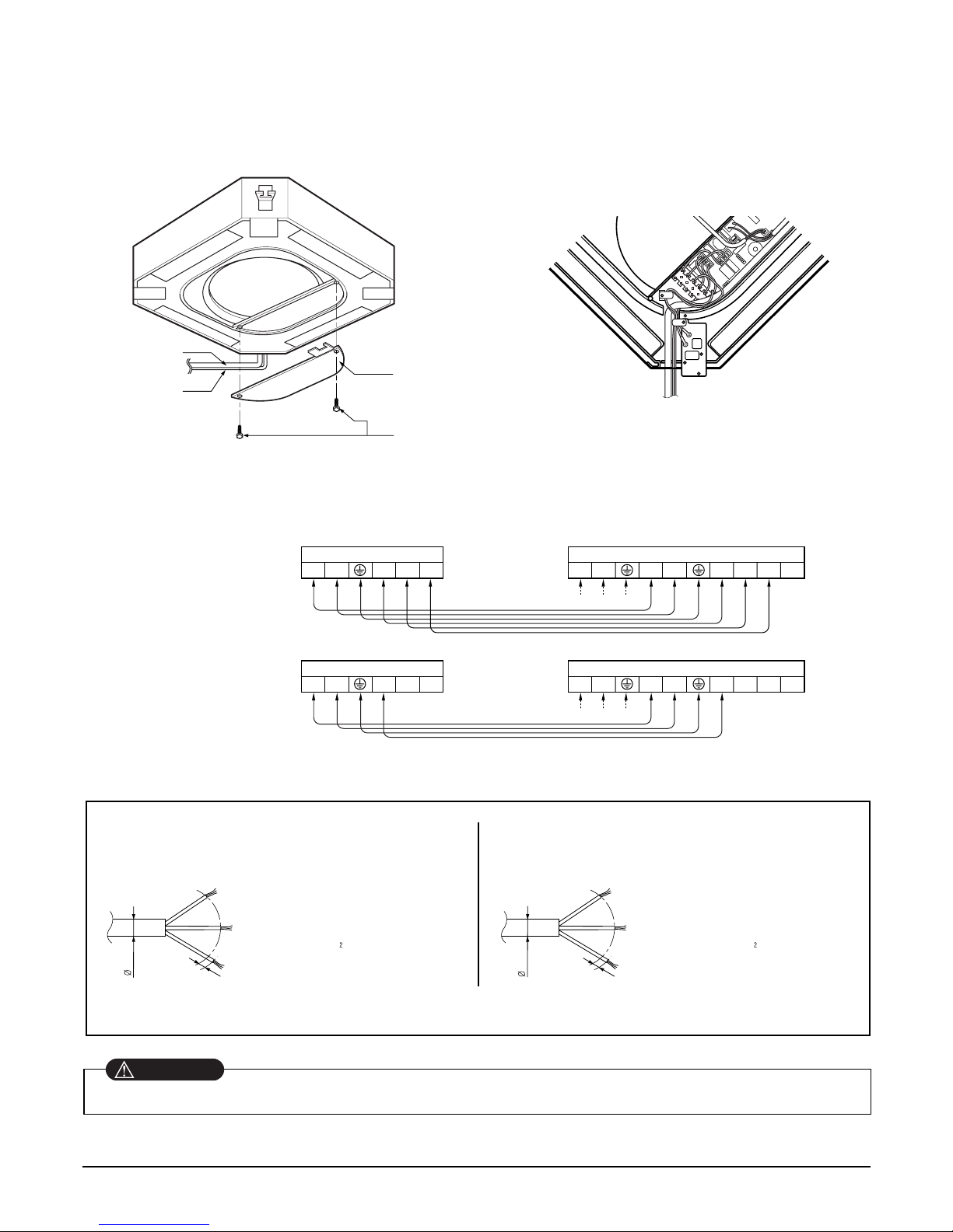
[Air inlet side view]
The power cord connected to the outdoor unit should be complied
with the following specifications (Rubber insulation, type H05RN-F
approved by HAR or SAA).
The connecting cable connected to the indoor and outdoor unit should
be complied with the following specifications (Rubber insulation,
type H05RN-F approved by HAR or SAA).
CAUTION
8.5mm
20mm
GN/YL
7.5mm
20mm
GN/YL
NORMAL
CROSS-SECTIONAL
AREA 0.75mm
NORMAL
CROSS-SECTIONAL
AREA 2.5mm
Terminal Block of Indoor Unit
3(L) 4(N)
567
1(L) 2(N) 3(L) 4(N)
5678
Terminal Block of Outdoor Unit
Power Cord
Terminal Block of Indoor Unit
3(L) 4(N)
567
1(L) 2(N) 3(L) 4(N)
5678
Terminal Block of Outdoor Unit
Power Cord
Control box cover
Indoor
power cord
Remote
controller
cord
Control box cover
fitting screw(2 units)
5. Wiring Connection
• Open the control box cover and connect the Remote controller cord and Indoor power wires.
• Heat Pump Model
• Cooling Model
Make sure that the screws of the terminal are free from looseness.
WARNING
If the supply cord is damaged, it must be replaced by a special cord or assembly available from the manufacturer or its service agent.
Page 26
- 26 -
Copyright ©2008 LG Electronics. Inc. All right reserved.
Only for training and service purposes
LGE Internal Use Only
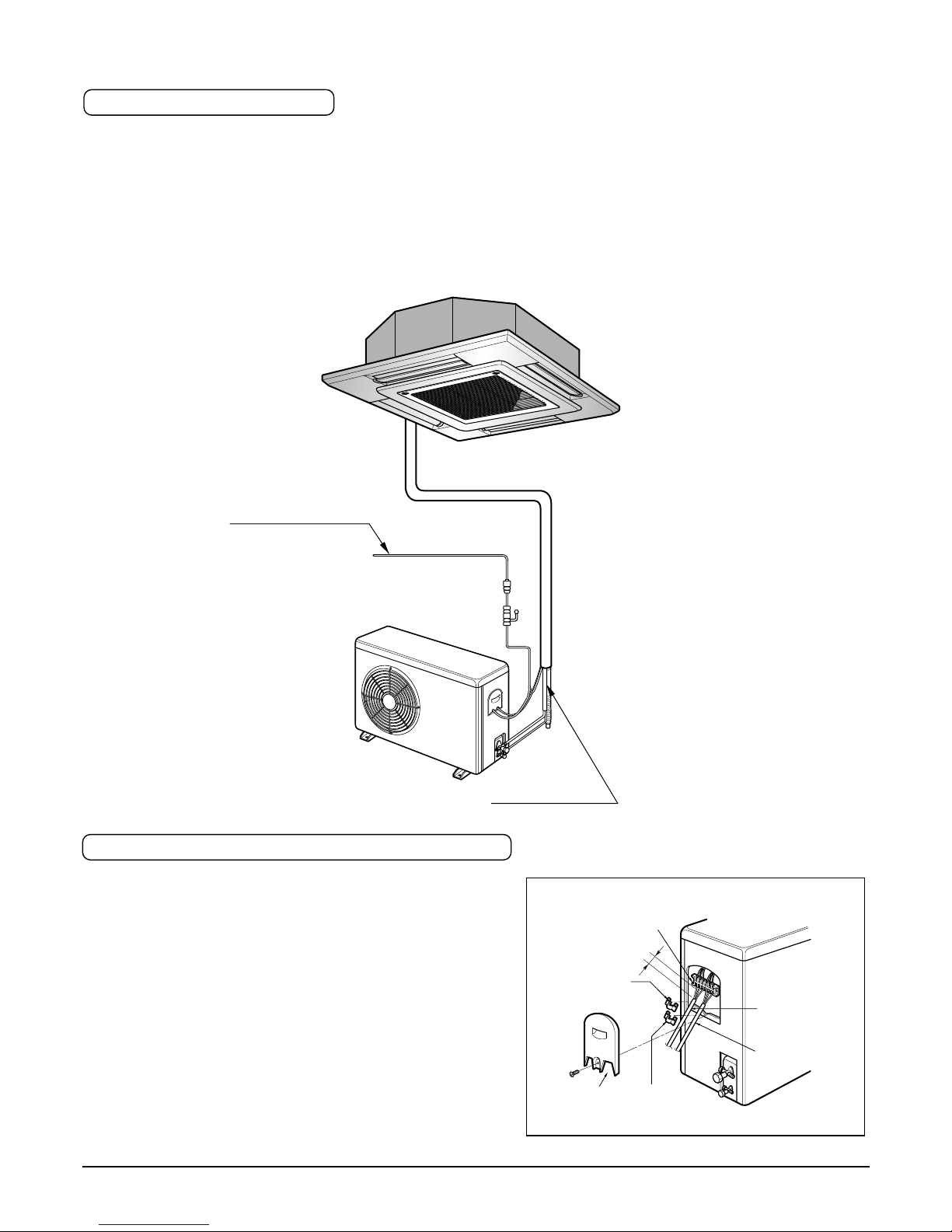
1. All wiring must comply with LOCAL REGULATIONS.
2. Select a power source that is capable of supplying the current required by the air conditioner.
3. Feed the power source to the unit via a distribution switch board designed for this purpose.
4. The terminal screws inside the control box may be loose due to vibration during transport.
Check the screws for loose connection.
(Running the air conditioner with loose connection can overload and damage electrical components.)
5. Always ground the air conditioner with a grounding wire and connector to meet the LOCAL REGULATION.
Main power source
Switch box
Refrigerant pipe
Circuit Breaker
Use circuit breaker or time delay fuse.
ELECTRICAL WIRING
CONNECTING THE CABLE TO OUTDOOR UNIT
1. Remove the Cover control from the unit by loosening a
screw.
Connect the wires to the terminals on the control
board individually as following.
2. Secure the cable onto the control board with the holder (clamper).
3. Refix the cover control to the original position with the
screw.
4. Use a recongnized circuit breaker 20A(18K, 24K)
between the power source and the unit. A disconnection device to adequately disconnect all supply lines
must be fitted.
Outdoor unit
Terminal block
Connecting
cable
Cover control
Holder for
connecting
cable
Over 5mm
Holder for
power supply
cord
Power supply
cord
Page 27
- 27 -
Copyright ©2008 LG Electronics. Inc. All right reserved.
Only for training and service purposes
LGE Internal Use Only
Copper
tube
90°
Slanted Uneven Rough
Pipe
Reamer
Point down
Flare nut
Copper tube
Bar
Copper pipe
Clamp handle
Red arrow mark
Cone
Yoke
Handle
Bar
"A"
Inclined
Inside is shining without scratches
Smooth all round
Even length
all round
Surface
damaged
Cracked Uneven
thickness
= Improper flaring =
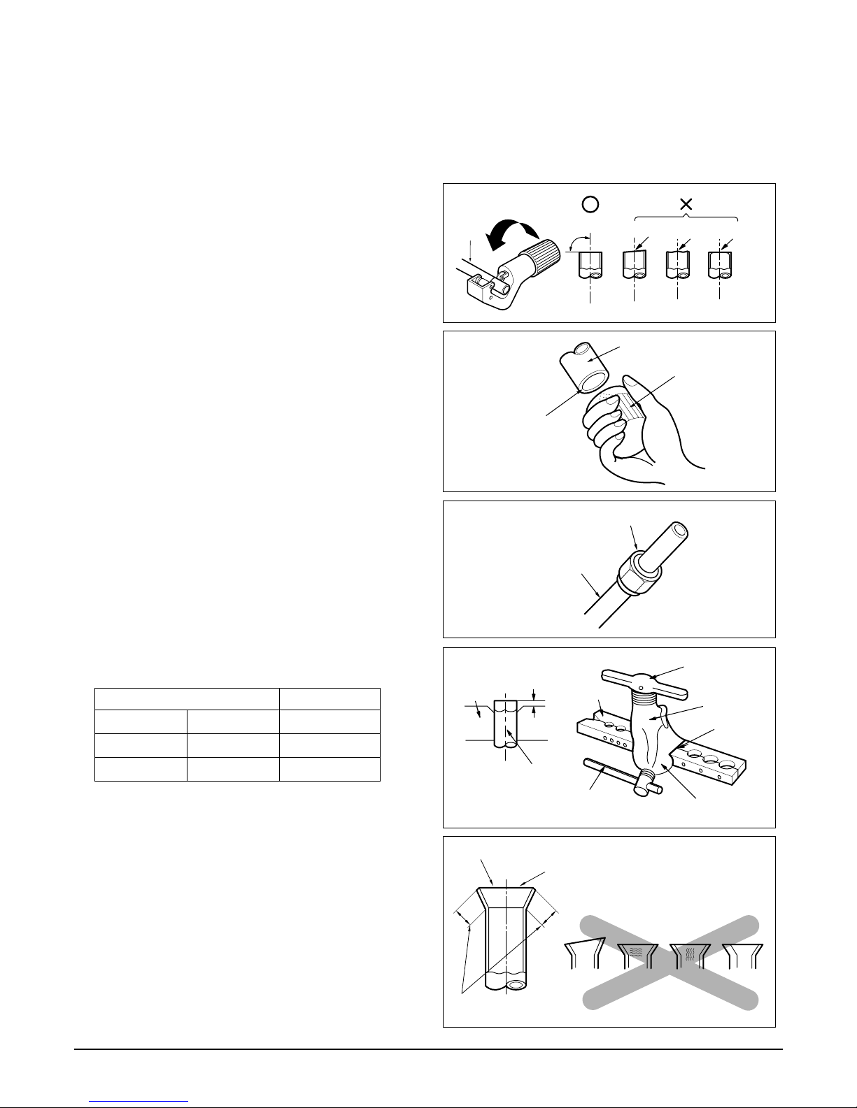
• Preparation of Piping
6. Connecting Pipes to the Indoor Unit
Main cause of gas leakage is defect in flaring work. Carry out correct flaring work in the following procedure.
1) Cutting the pipes and the cable.
■ Use the accessory piping kit or the pipes purchased
locally.
■ Measure the distance between the indoor and the outdoor unit.
■ Cut the pipes a little longer than measured distance.
■ Cut the cable 1.5m longer than the pipe length.
2) Burrs removal
■ Completely remove all burrs from the cut cross section
of pipe/tube.
■ Put the end of the copper tube/pipe to downward direction as you remove burrs in order to avoid to let burrs
drop in the tubing.
3) Putting nut on
■ Remove flare nuts attached to indoor and outdoor units,
than put them on pipe/tube having completed burr
removal.
(Not possible to put them on after flaring work)
4) Flaring work
■ Carry out flaring work using flaring tool as shown below.
Firmly hold copper tube in a bar(or die) as indicated
dimension in the table above.
5) Check
■ Compare the flared work with figure below.
■ If flare is noted to be defective, cut off the flared section
and do flaring work again.
Outside diameter A
mm inch mm
Ø6.35 1/4 0.5~0.8
Ø15.88 5/8 0.8~1.0
Page 28
- 28 -
Copyright ©2008 LG Electronics. Inc. All right reserved.
Only for training and service purposes
LGE Internal Use Only
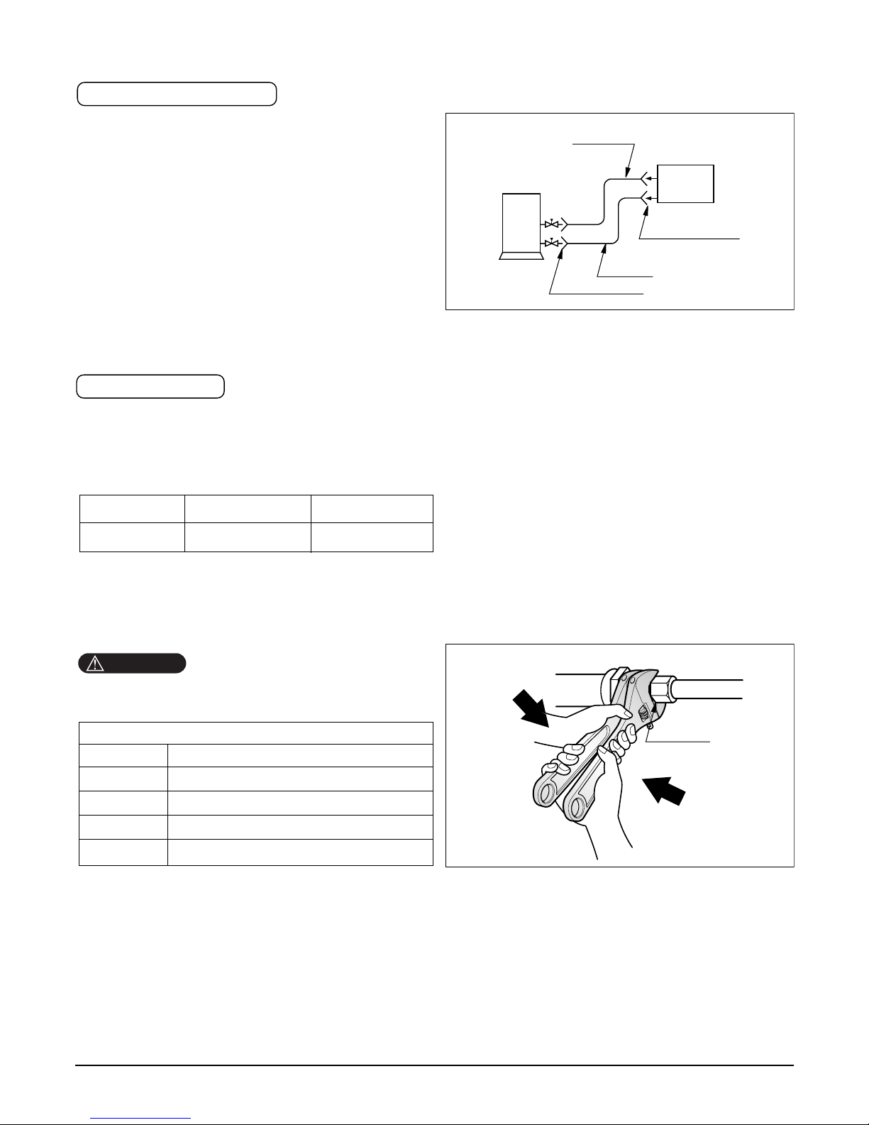
1. Form the piping according to its routing. Avoid bending and bending back the same piping point more
than three times. (This will result in hardening of
pipe.)
2. After deforming the piping, align centers of the union
fitting of the indoor unit and the piping, and tighten
them firmly with wrenches.
3. Connect pipe to the service valve or ball valve which
is located below the outdoor unit.
4. After completing the piping connection, be sure to
check if there is gas leakage in indoor and outdoor
connection.
After completing the piping connection, execute vacuum
drying for the connecting piping and the indoor unit.
The vacuum drying must be carried out using the service ports of both the liquid and gas side valves.
Use two wrenches and tighten with regular torque.
Outdoor
unit
Liquid side
Flare connection
Flare connection
Gas side
Indoor
unit
Union
Flare nut fastening torque
Ø6.35mm 1.8kg.m
Ø9.52mm 4.0kg.m
Ø12.7mm 5.5kg.m
Ø15.88mm 6.6kg.m
Ø19.05mm 6.6kg.m
Model Liquid side piping Gas side piping
18K, 24K Btu/h
Ø 6.35mm Ø15.88mm
Piping Connection
Vacuum drying
CAUTION
Page 29
- 29 -
Copyright ©2008 LG Electronics. Inc. All right reserved.
Only for training and service purposes
LGE Internal Use Only
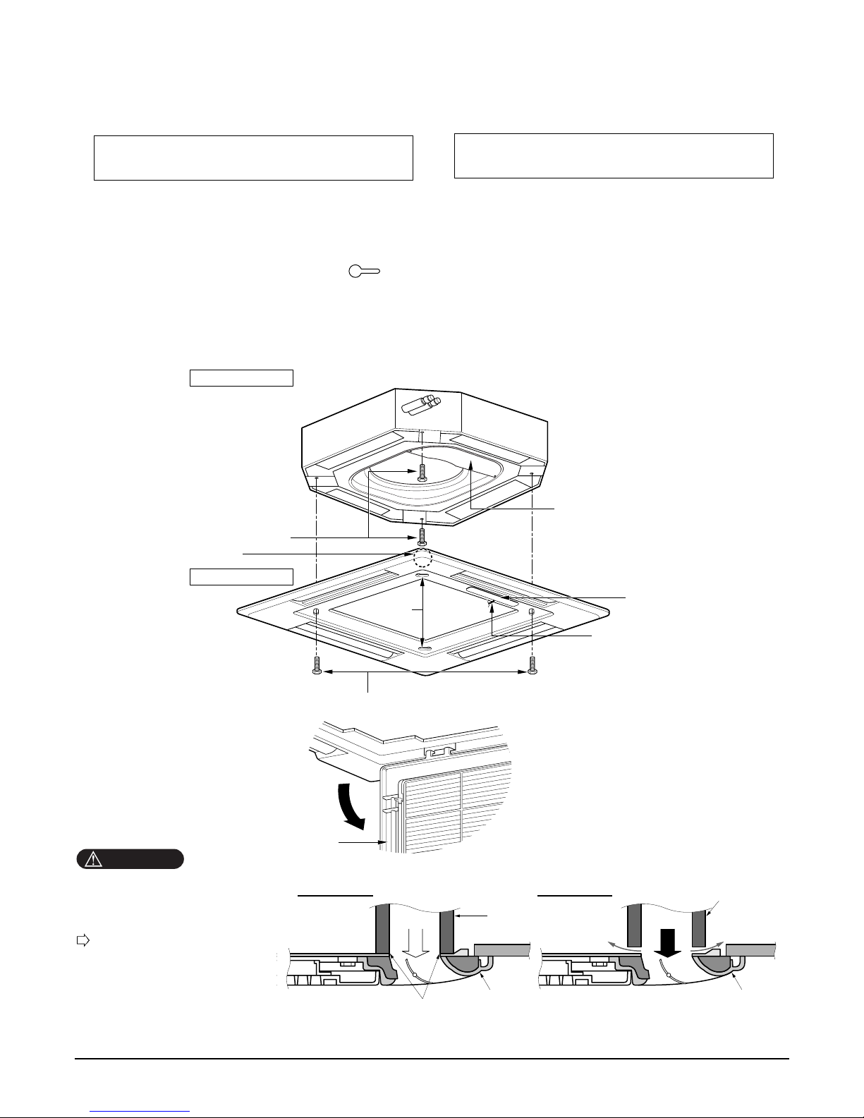
7. Installation of Decoration Panel
1. Temporarily fix two decoration panel fixing screws (hexagon M5 screw) on the unit body. (Tighten by
amount 10mm in length.)
The fixing screws (hexagon M5 screw) are included the indoor unit box.
2. Remove the air inlet grille from the decoration panel. (Remove the hook for the air inlet grille cord.)
3. Hook the decoration panel key hole ( ) on the screws fixed in step above, and slide the panel so
that the screws reach the key hole edge.
4. Retighten completely two temporarily fixed screws and other two screws. (Total 4 screws)
5. Connect the louver motor connector and display connector.
6. After tightening these screws, install the air inlet grille (including the air filter).
Decoration panel fixing screws
(hexagon M5 screws)
Temporally fitting at 2 places
(Tightening about 10mm)
Control box cover
Piping side
Inlet GrilleInlet Grille
Inlet Grille
Louver motor
Decoration panel fixing screws
(Hexagon M5 screw)
Air conditioner unit
Decoration panel
Key holes
Display
Lead wire for
louver motor and
display
The decoration panel has its installation
direction.
Before installing the decoration panel,
always remove the paper template.
CAUTION
Install certainly the decoration panel.
Cool air leakage causes sweating.
Water drops fall.
Air conditioner
unit
Ceiling
board
Decoration panel
Decoration
panel
Fit the insulator (this part) and
be careful for cool air leakage
Good example
Air
Cool air leakage
(no good)
Bad example
Ceiling
board
Air conditioner unit
Page 30
- 30 -
Copyright ©2008 LG Electronics. Inc. All right reserved.
Only for training and service purposes
LGE Internal Use Only
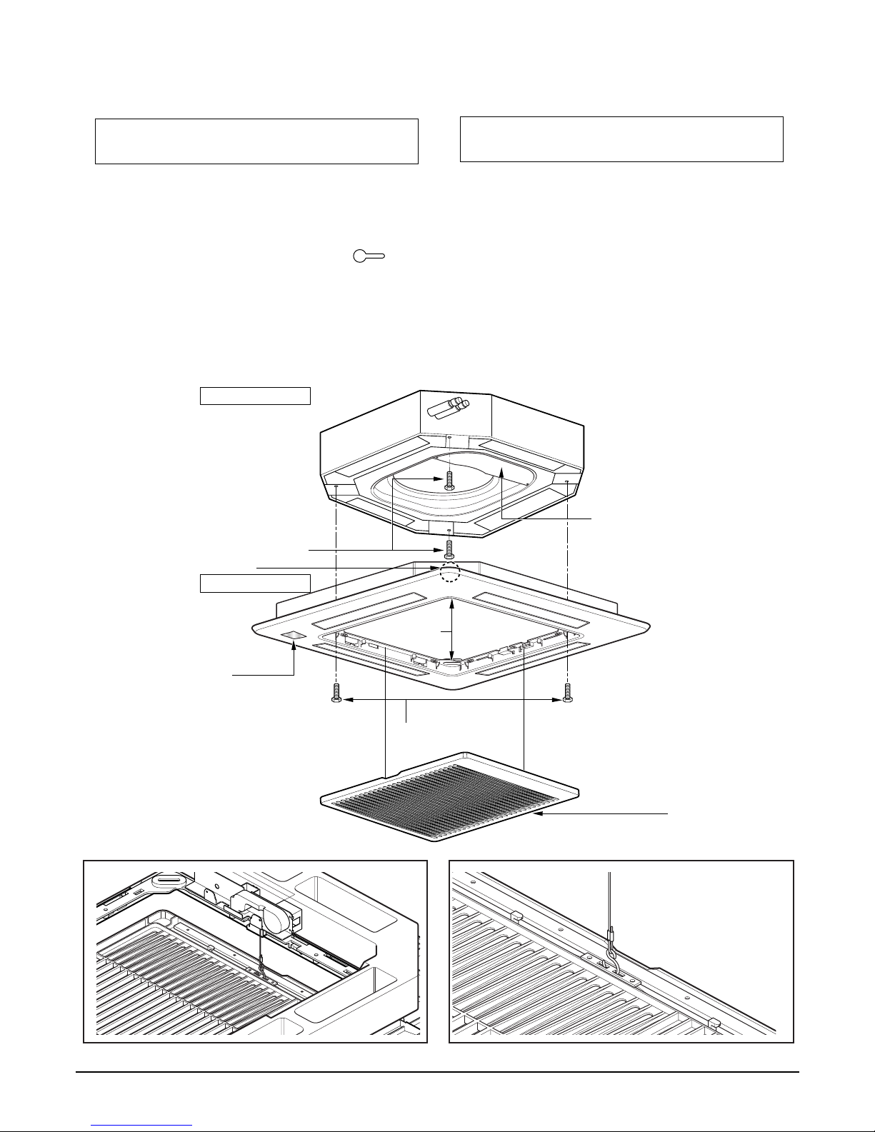
Decoration panel fixing screws
(hexagon M5 screws)
Temporally fitting at 2 places
(Tightening about 10mm)
Control box cover
Piping side
Inlet Grille
Louver motor
Decoration panel fixing screws
(Hexagon M5 screw)
Air conditioner unit
Decoration panel
Key holes
Inlet grille
Display
8. Installation of Decoration Panel(Elevation Grille)
1. Temporarily fix two decoration panel fixing screws (hexagon M5 screw) on the unit body. (Tighten by
amount 10mm in length.)
The fixing screws (hexagon M5 screw) are included unit box.
2. Remove the air inlet grille from the decoration panel. (Remove the hook for the air inlet grille cord.)
3. Hook the decoration panel key hole ( ) on the screws fixed in step above, and slide the panel so
that the screws reach the key hole edge.
4. Retighten completely two temporarily fixed screws and other two screws. (Total 4 screws)
5. Connect the louver motor connector display connector, elevation grille connector and power supply connector
6. After tightening these screws, install the air inlet grille (including the air filter).
The decoration panel has its installation
direction.
Before installing the decoration panel,
always remove the paper template.
Page 31
- 31 -
Copyright ©2008 LG Electronics. Inc. All right reserved.
Only for training and service purposes
LGE Internal Use Only
• Don't lay any material upon suction grill.
• Suction grill comprises 2 strands of wire. If any substance is placed on it then balance may be destroyed so that
the substance would drop down and cause a breakage or damage. Also the matter may cause trouble owing to
which the grill would not be correctly inserted at front panel.
• Don't shake suction grill. Or else there is worry that it may collide with adjacent material and the suction grill fall
down.
• Don't pull suction grill. Don't draw out suction grill irrationally. Or else there is worry that lift grill drive part is
damaged and suction grill might drop down.
• Don't place obstacle in lift passage of lift grill.
When suction grill descends, it automatically stops at a certain distance.
If there is any obstacle in lift passage, suction grill might drop down and there may be caused trouble failure of lift grill drive part.
• Turn off the air conditioner operation button before operating the lift grill.
Always stop the air conditioner operation for safety when suction grill descends.
• Don't damage lift rope by a sharp material. Or else there is worry about suction grill dropping because of rope
cutoff.
Page 32
- 32 -
Copyright ©2008 LG Electronics. Inc. All right reserved.
Only for training and service purposes
LGE Internal Use Only
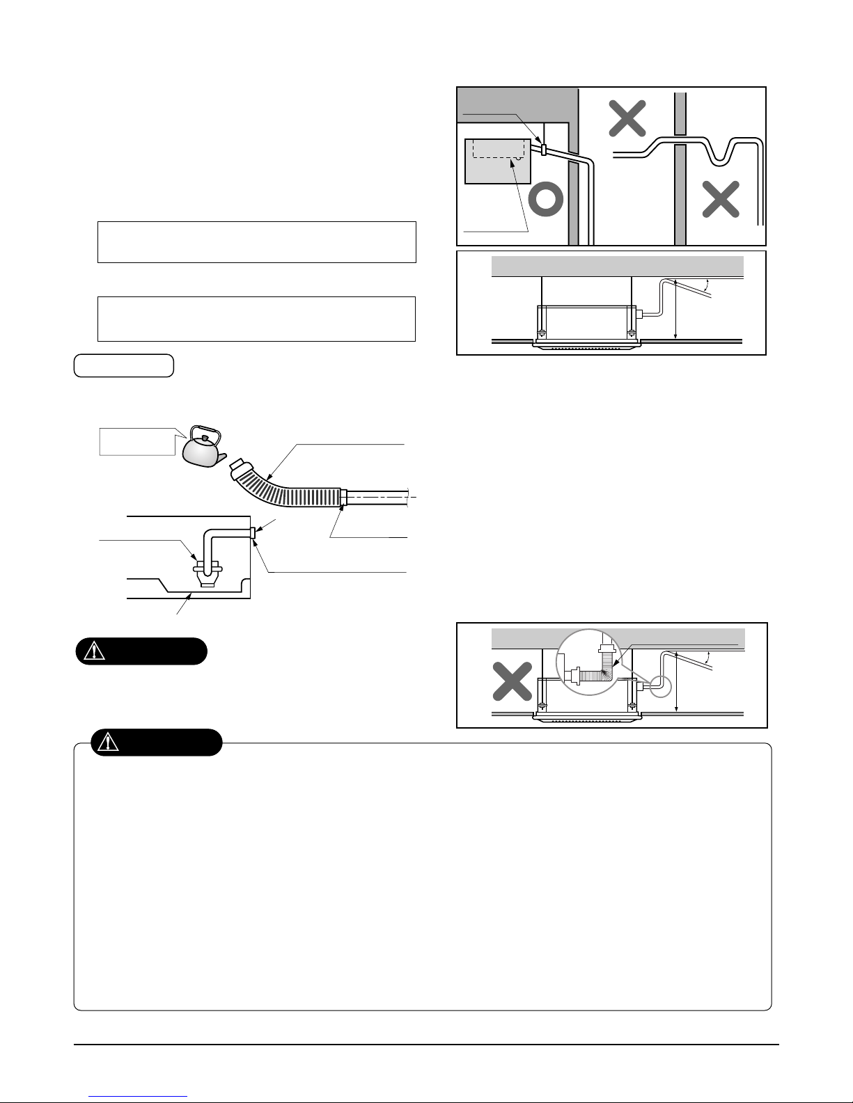
9. Indoor Unit Drain Piping
• Drain piping must have down-slope (1/50 to 1/100): be sure
not to provide up-and-down slope to prevent reversal flow.
• During drain piping connection, be careful not to exert extra
force on the drain port on the indoor unit.
• The outside diameter of the drain connection on the indoor
unit is 32mm.
•
Be sure to install heat insulation on the drain piping.
Piping material: Polyvinyl chloride pipe VP-25
and pipe fittings
The air conditioner uses a drain pump to drain water.
Use the following procedure to test the drain pump operation:
• Connect the main drain pipe to the exterior
and leave it provisionally until the test
comes to an end.
• Feed water to the flexible drain hose and
check the piping for leakage.
• Be sure to check the drain pump for normal
operating and noise when electrical wiring
is complete.
• When the test is complete, connect the
flexible drain hose to the drain port on the
indoor unit.
Heat insulation material: Polyethylene foam with
thickness more than 8 mm.
Drain test
Maintenance
drain port
Upward
routing
not allowed
Pipe clamp
Indoor unit
1/50~1/100
MAX 700mm
Feed water
Drain Pump
Drain pan
Flexible drain hose
(accessory)
Main
drain pipe
Glue the joint
Drain
port
Drain hose connection
Use the clip (accessory)
CAUTION
The supplied flexible drain hose should not be curved,
neither screwed. The curved or screwed hose may
cause a leakage of water.
1/50~1/100
MAX 700mm
Flexible drain hoseFlexible drain hose
After the confirmation of the above conditions, prepare the wiring as follows:
1) Never fail to have an individual power specialized for the air conditioner. As for the method of wiring, be guided by the
circuit diagram pasted on the inside of control box cover.
2) Provide a circuit breaker switch between power source and the unit.
3) The screw which fasten the wiring in the casing of electrical fittings are liable to come loose from vibrations to which the
unit is subjected during the course of transportation. Check them and make sure that they are all tightly fastened. (If they
are loose, it could give rise to burn-out of the wires.)
4) Specification of power source
5) Confirm that electrical capacity is sufficient.
6) Be sure that the starting voltage is maintained at more than 90 percent of the rated voltage marked on the name plate.
7) Confirm that the cable thickness is as specified in the power sources specification.
(Particularly note the relation between cable length and thickness.)
8) Never fail to equip a leakage breaker where it is wet or moist.
9) The following troubles would be caused by voltage drop-down.
• Vibration of a magnetic switch, damage on the contact point there of, fuse breaking, disturbance to the normal function of a
overload protection device.
• Proper starting power is not given to the compressor.
CAUTION
Page 33
- 33 -
Copyright ©2008 LG Electronics. Inc. All right reserved.
Only for training and service purposes
LGE Internal Use Only
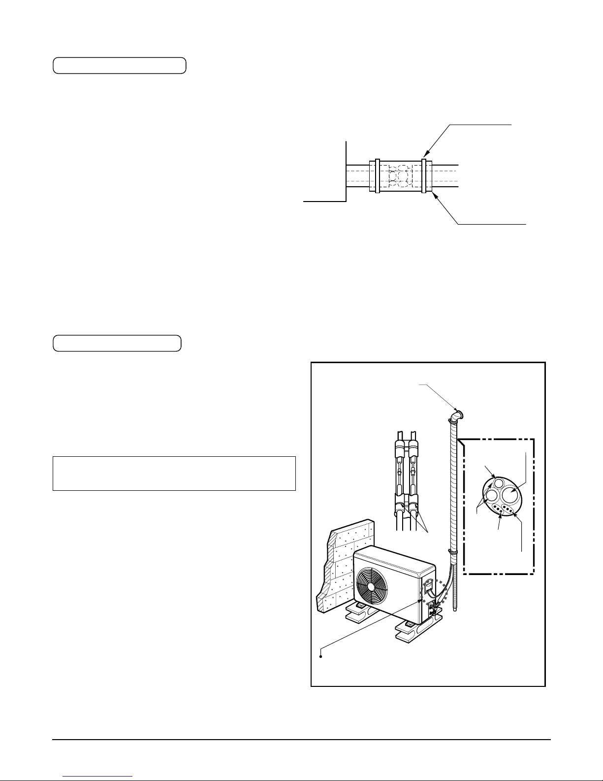
1. Use the heat insulation material for the refrigerant piping which has an excellent heat-resistance (over 120°C).
2. Precautions in high humidity circumstance:
This air conditioner has been tested according to the
"KS Standard Conditions with Mist" and confirmed
that there is not any default. However, if it is operated
for a long time in high humid atmosphere (dew point
temperature: more than 23°C), water drops are liable
to fall. In this case, add heat insulation material
according to the following procedure:
• Heat insulation material to be prepared... Adiabatic
glass wool with thickness 10 to 20mm.
• Stick glass wool on all air conditioners that are located in ceiling atmosphere.
• In addition to the normal heat insulation (thickness: more than 8mm) for refrigerant piping (gas piping: thick pip-
ing) and drain piping, add further 10mm to 30mm thickness material.
Indoor unit
Thermal insulator
(accessory)
Fastening band
(accessory)
Refrigerant piping
HEAT INSULATION
1. Wrap the connecting portion of indoor unit with
the Insulation material and secure it with two
Plastic Bands. (for the right pipings)
•If you want to connect an additional drain hose, the
end of the drain-outlet should keep distance from
the ground. (Do not dip it into water, and fix it on the
wall to avoid swinging in the wind.)
2. Tape the Pipings, drain hose and Connecting
Cable from bottom to top.
3. Form the pipings gathered by taping along the
exterior wall and fix it onto the wall by saddle or
equivalent.
In case of the Outdoor unit being installed
below position of the Indoor unit.
FORM THE PIPINGS
Trap is required to prevent water from entering
into electrical parts.
Seal a small opening
around the pipings
with gum type sealer.
Taping
Drain hose
Pipings
Connecting
cable
Plastic Band
Power supply
cord
Page 34
- 34 -
Copyright ©2008 LG Electronics. Inc. All right reserved.
Only for training and service purposes
LGE Internal Use Only
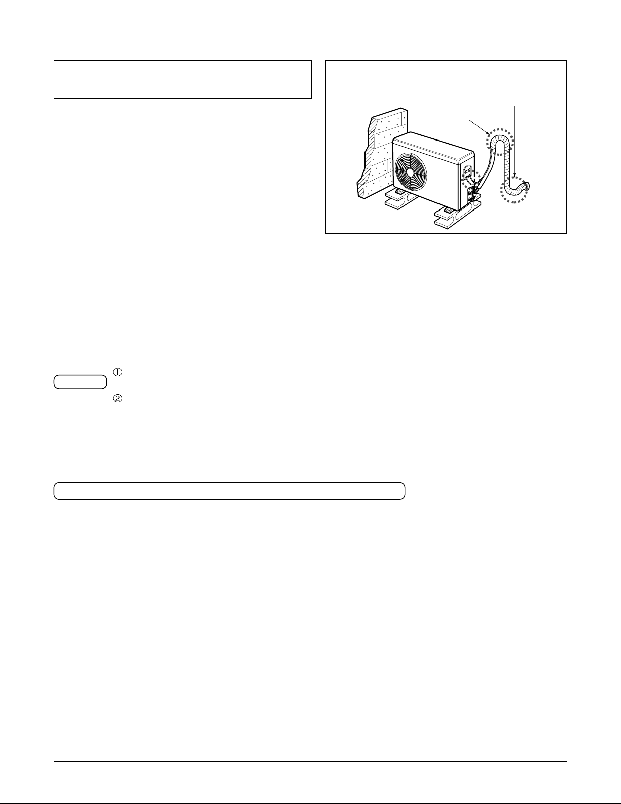
2. Tape the Pipings and Connecting cable from bottom to top.
3. Form the pipings gathered by taping along the
exterior wall, and make the trap prevent water
from entering into the room.
4. Fix the pipings onto the wall by saddle or equivalent.
In case of the Outdoor Unit being installed
above position of the Indoor Unit.
Seal a small opening
around the pipings
with gum type sealer.
Trap
1) PRECAUTIONS IN TEST RUN
• The initial power supply must provide at least 90% of the rated voltage.
Otherwise, the air conditioner should not be operated.
For test run, carry out the cooling operation first even during winter season. If heating operation is
carried out first, it leads to the trouble of compressor.
Carry out the test run more than 5 minutes without stopping.
(Test run will be cancelled 18 minutes later automatically)
• The test run is started by pressing the room temperature checking button and down timer button for 3 seconds at the same time.
• To cancel the test run, press any button.
• After completing work, be sure to measure and record trial run properties, and store measured data, etc.
• Measuring data are room temperature, outside temperature, suction temperature, blow out temperature,
air velocity, air volume, voltage, current, presence of abnormal vibration and noise, operating pressure, piping
temperature.
• As to the structure and appearance, check following items.
CHECK THE FOLLOWING ITEMS WHEN INSTALLATION IS COMPLETE
Caution
❏ Is the circulation of air adequate?
❏ Is the drainage OK?
❏ Is the heat insulation complete
(refrigerant and drain piping)?
❏ Is there any leakage of refrigerant?
❏ Does the romote controller works properly?
❏ Is there any error on wiring?
❏ Aren't terminal screws loosened?
M4......118N.cm{12kgf.cm} M5......196N.cm{20kgf.cm}
M6......245N.cm{25kgf.cm} M8......588N.cm{60kgf.cm}
Test running
Page 35
- 35 -
Copyright ©2008 LG Electronics. Inc. All right reserved.
Only for training and service purposes
LGE Internal Use Only
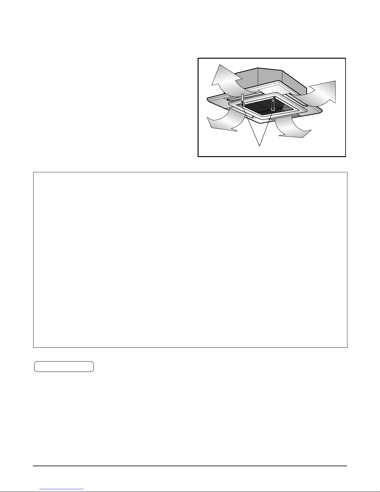
Thermometer
2) Connection of power supply
1. Connect the power supply cord to the independent
power supply.
• Circuit breaker is required.
2. Operate the unit for fifteen minutes or more.
3) Evaluation of the performance
1. Measure the temperature of the intake and dis-
charge air.
2. Ensure the difference between the intake tempera-
ture and the discharge one is more than 8°C (Cooling) or reversely (Heating).
Teach the customer the operation and maintenance procedures, using the operation manual (air filter cleaning,
temperature control, etc.).
HAND OVER
CAUTION
After the confirmation of the above conditions, prepare the wiring as follows:
1) Never fail to have an individual power specialized for the air conditioner. As for the method of
wiring, be guided by the circuit diagram pasted on the inside of control box cover.
2) Provide a circuit breaker switch between power source and the unit.
3) The screw which fasten the wiring in the casing of electrical fittings are liable to come loose from
vibrations to which the unit is subjected during the course of transportation. Check them and
make sure that they are all tightly fastened. (If they are loose, it could give rise to burn-out of the
wires.)
4) Specification of power source
5) Confirm that electrical capacity is sufficient.
6) Be sure that the starting voltage is maintained at more than 90 percent of the rated voltage marked
on the name plate.
7) Confirm that the cable thickness is as specified in the power sources specification.
(Particularly note the relation between cable length and thickness.)
8) Never fail to equip a leakage breaker where it is wet or moist.
9) The following troubles would be caused by voltage drop-down.
• Vibration of a magnetic switch, damage on the contact point there of, fuse breaking, disturbance to the nor-
mal function of a overload protection device.
• Proper starting power is not given to the compressor.
Page 36
- 36 -
Copyright ©2008 LG Electronics. Inc. All right reserved.
Only for training and service purposes
LGE Internal Use Only
Optional Operation
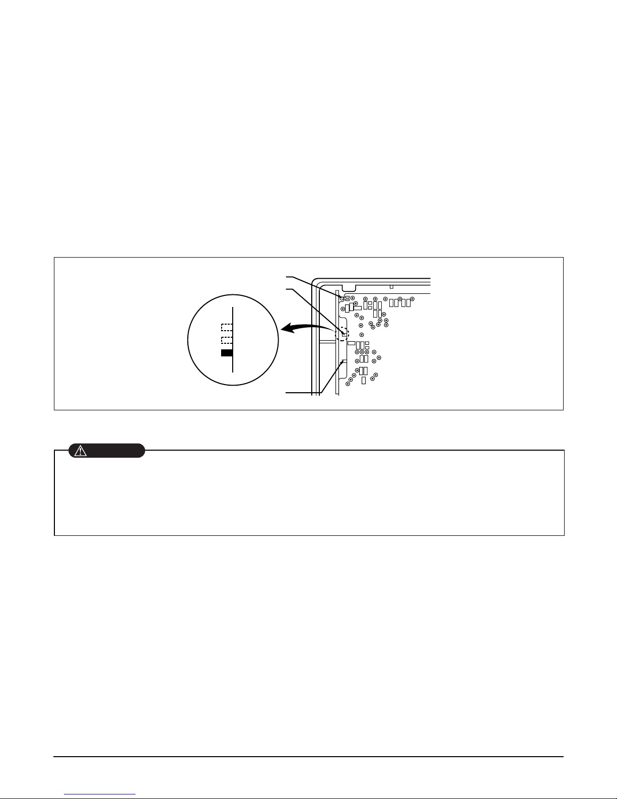
1) Two Thermistor System
(1) Open the rear cover of the wired remote-controller to set the mode.
(2) Select one of three selectable modes as follows.
• Position 1:
The room temperature is controlled by the thermistor of the main body.
• Position 2:
The room themperature is controlled by the thermistor of the wired remote-controller, control the
temperature according to the position of wired remote-controller.
• Position 3:
The room temperature is controlled by lower temperature between the temperature of main body and of
remote-controller sensor.
(3) Move the slide switch to set position.
(4) Close the rear cover and check if it works normally.
TH
R14H
SW TH
REMO
MAIN
2TH
OP7
R18H
R17H
OP6
LO
STAND
SW HIGH
HI
R03S
C070
R04S
R02S
R01S
OP3
OP2 OP1
R19H
R11H
R13H R12H
OP5R16H OP4
R15H
CO1H
REMO
Room Temp. sensor
2TH
MAIN
Position 2
Position 1
Position 3
Slide switch for ceiling height
Slide switch for 2 Thermistor
• Select the position after counselling with a customer.
• In case of cooling mode, room temperature is controlled by the main body sensor.
• To control the room temperature by a wired remote controller, install controller(room temp. sensor) to sense
the temperature more accurately.
• Maunfactured in the position 3.
CAUTION
Page 37
- 37 -
Copyright ©2008 LG Electronics. Inc. All right reserved.
Only for training and service purposes
LGE Internal Use Only
2) Adjusting air volume to the height of ceiling
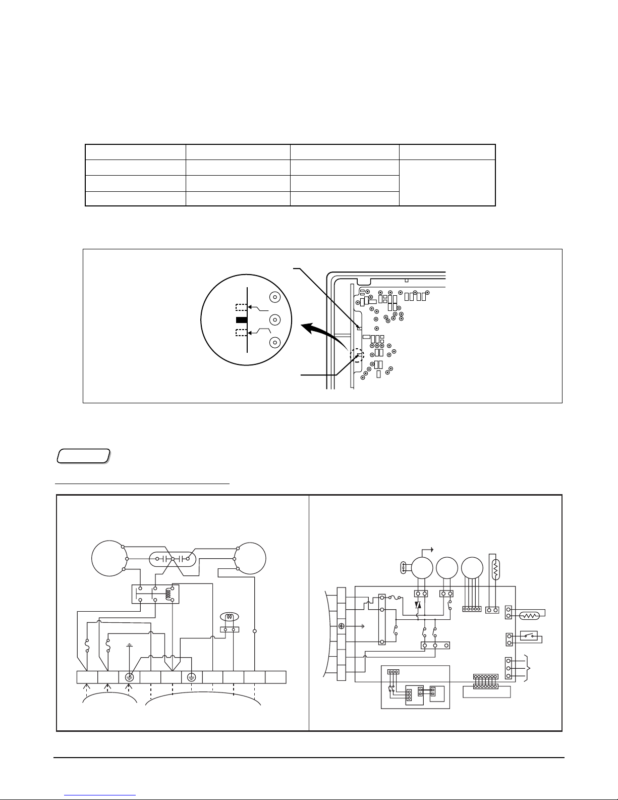
You can choose the RPM(or air volume) of indoor motor according to the height of ceiling to supply the comfortable atmosphere to consumers.
Procedure
1. Choose the selectable position in the table after measuring the height of ceiling.
2. In the case of changing the height as "high" or "low", open the rear cover of the wired remote-controller.
3. Move the slide switch to the set position.
4. Close the rear cover and check if it works nomally.
Wiring Diagram f
or Heat pump
TH
R14H
SW TH
REMO
MAIN
2TH
OP7
R18H
R17H
OP6
LO
STAND
SW HIGH
HI
R03S
C070
R04S
R02S
R01S
OP3
OP2 OP1
R19H
R11H
R13H R12H
OP5R16H OP4
R15H
CO1H
Lo
Hi
STAND
Slide switch for ceiling height
Slide switch for 2 Thermistor
Standard
(Default)
Low ceiling
High Ceiling
Ceiling height Mode of slide switch Change of air volume Remark
more than 3.3m High Ceiling Increasing
2.7~3.3m Standard -
less than 2.7m Low Ceiling Decreasing
Maunfactured in stan-
dard mode
NOTICENOTICE
OUTDOOR WIRING DIAGRAM INDOOR WIRING DIAGRAM
COMP
R
S
H
42861
0
CF
BL
YL
OR
BK
TB2
BR
BR
BR
BR
BL
BL
BL
BL
BL
GN/YL
GN/YL
BK
BK
RD
CAPACITOR
REVERSING
VALVE
RD
C
POWER
RELAY
FAN
MOTOR
FUSE 5A
FUSE 5A
POWER
INPUT
TO INDOOR UNIT
TERMINAL
BLOCK
1(L)2(N
)
3(L)4(N
)
5
6
7
8
INDOOR
MOTOR
DRAIN
PUMP
STEP
MOTOR
TEMP.
THERMISTOR
PIPE
THERMISTOR
REMOTE
CONTROL
FLOAT S/W
CN - DISP
DISPLAY PCB
(
OPTION
)
AIR
CLEANER
H.V. ASSY
DOOR S/W
TERMINAL
BLOCK
TO OUTDOOR UNIT
BR
YL
BK
OR
BL
BL
BR
GN/YL
RD
BK
YL
BL
GN
/
YL
OUT FAN
COMP
4 WAY
RD
BK
WH
RD
BK
3
(
L
)
4
(
N
)
5 6 7
FUSE T3.15A
Page 38
- 38 -
Copyright ©2008 LG Electronics. Inc. All right reserved.
Only for training and service purposes
LGE Internal Use Only
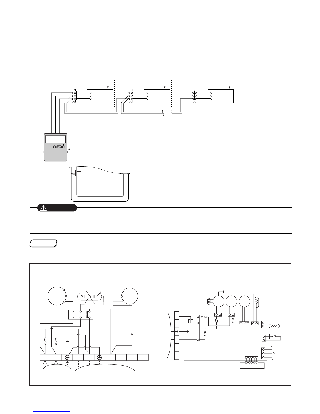
3) Group Control(Optional Wiring)
]Wiring Diagram for Cooling only
• Be careful not to exchange the color of wires.
• The maximum length of connecting wire should be below 200m(25Ω) on connecting each units.
• Use a wire more than 0.5mm
2
CAUTION
NOTICE
OUTDOOR WIRING DIAGRAM INDOOR WIRING DIAGRAM
INDOOR
MOTOR
DRAIN
PUMP
STEP
MOTOR
TEMP.
THERMISTOR
PIPE
THERMISTOR
REMOTE
CONTROL
FLOAT S/W
CN - DISP
DISPLAY PCB
TERMINAL
BLOCK
TO OUTDOOR UNIT
BR
YL
BK
OR
BL
BL
BR
GN/YL
RD
BL
GN
/
YL
COMP
3
(
L
)
4
(
N
)
5 6 7
FUSE T3.15A
COMP
R
S
H
42861
0
CF
BL
YL
OR
BK
TB2
BR
BR
BR
BR
BL
BL
BL
BL
BL
GN/YL
GN/YL
BK
RD
CAPACITOR
RD
C
POWER
RELAY
FAN
MOTOR
FUSE 5A
FUSE 5A
POWER
INPUT
TO INDOOR UNIT
TERMINAL
BLOCK
1(L)2(N
)
3(L)4(N
)
5
6
7
8
It operates maximum 16 Units by only one Wired Remote Controller,
and each Unit starts sequentially to prevent overcurrent.
Operation unit
ZONE
1234
Humidify
JET
AUTO
AUTO SWING OPERATION
FAN SPEED
Program set
SUB FUNCTION
SET TEMP
Room Temp
HI
MED
LO
Heater
Defrost
Filter
Preheat
Out door
Time
Timer
On
Set no. Time
Off
01 03 05 07 09 11 13 15 17 19 21 23
Indoor Unit 1
Ter minal(Local Supply)
Block
Ter minal(Local Supply)
Block
Ter minal(Local Supply)
Block
Main PCB
#1
Main PCB
#2
Main PCB
#16
Wired Remote Controller
(Standard)
Indoor Unit 2
Main PCB
Indoor Unit 16
Connector
RED(12V)
YL(SIGNAL)
BR(GND)
RED(12V)
YL(SIGNAL)
BR(GND)
YL(SIGNAL)
BR(GND)
Connecting Cable(Local Supply)
Connector Connector
....
....
YL(SIGNAL)
BR(GND)
YL(SIGNAL)
BR(GND)
YL(SIGNAL)
BR(GND)
Remote
Controller
PCB
Single
Group
Slide Switch2
• Using the supplied Wired Remote Controller, wire
them like above.
• Move slide switch 2 to "Group" position.
• Ensure that the color of wire.
Page 39
Copyright ©2008 LG Electronics. Inc. All right reserved. Only for training and service purposes
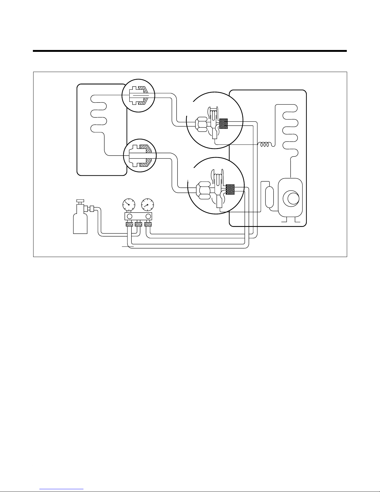
Cycle
• Installation
(1) Connect the piping between the indoor and out-
door unit firmly.
– Incorrect connection may cause the leakage and
incomplete vacuuming.
(2) Attach the charging hose (manifold gage) to the
service port.
– Charging hose is necessary to check the pressure
and to inject N2 for leakage test.
– The valve of charging hose must be closed before
being connected.
(3) Inject the 100~300g N
2 through the charging hose
opening the valve.
(4) Check the joint part using a gas detector or soapy
water for leakage.
– On checking, the service valve of main service port
must be closed, this test is only for checking whether
pipe connection is OK or not.
(5) If there is no leakage, discharge N
2 in piping com-
pletely into tank for retrieving.
– Completely discharge is needed for vacuuming.
– If leakage is found, please fasten the joint more tight-
ly.
(6) After closing the valve of charging hose, discon-
nect the tank and connect the vacuum pump to
charging hose and open the valve again for vacuuming.
(7) Turn on the vacuum pump until the pressure drops
below 0 kg/cm
2
.
(8) After vacuuming, disconnect the vacuum pump and
open the spindle of service port (liquid-side) slightly for 30 sec and then open the spindle of service
port (gas side) with hexagonal wrench.
(9) Open the liquid side completely first and then the
gas side fully in order.
Lo
Purge the air
Outdoor unit
Indoor unit
Liquid side
Gas side
3-Way
valve
3-Way
valve
Gas cylinder
R22
1. Installation (Connecting the piping between indoor and outdoor unit)
Page 40
- 40 -
Copyright ©2008 LG Electronics. Inc. All right reserved.
Only for training and service purposes
LGE Internal Use Only
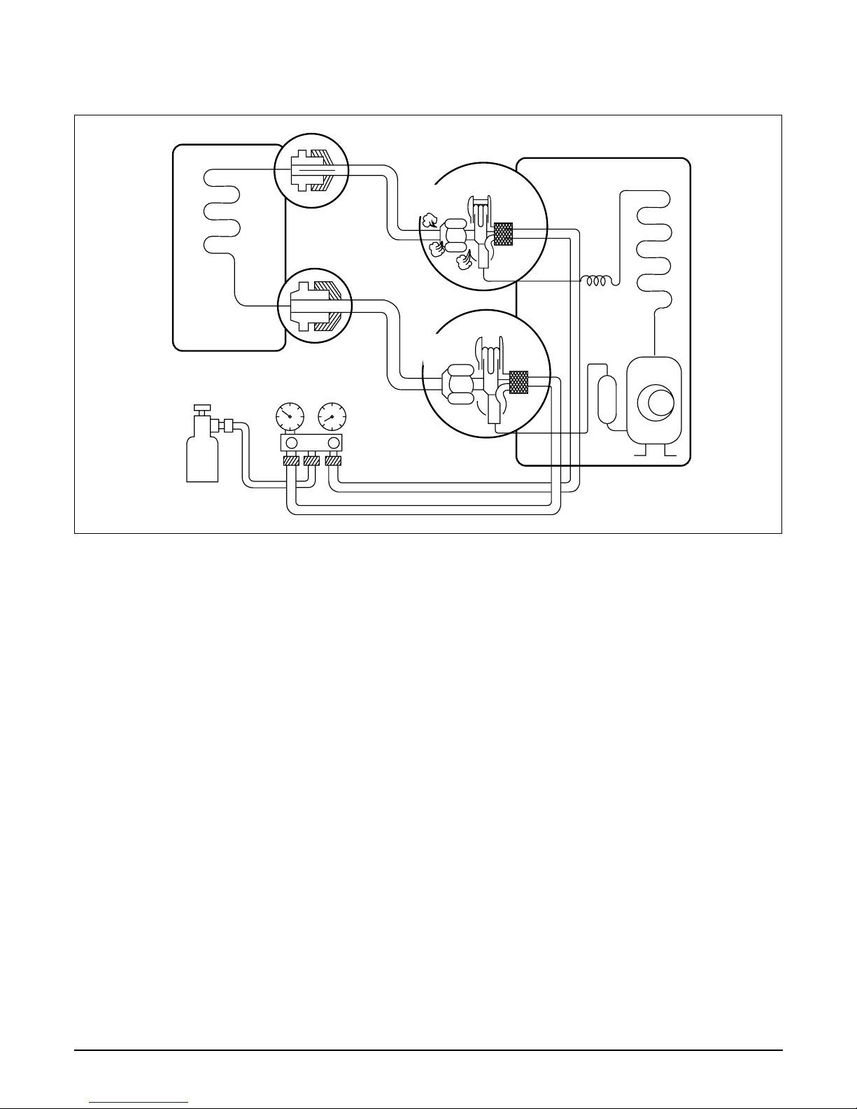
2. Disconnection (on moving)
• Disconnection
(1) Attach the charging hose (manifold gage) to
the service port.
– Connect the manifold gage once to the service
port not stopping. Stopping in the middle of
process may cause the leakage.
(2) Purge the air in hose into special device such
as retrieving tank opening the valve of charging- hose (gas side) slightly and then close it
tightly.
(3) Operate the air conditioner for 10~15 min until
cycle is stabilized.
(4) Close the spindle of service port (liquid side-
high pressure) and wait till pressure of gas
side (low pressure) drops below 0 kgf/cm2.
(5) After the needle of gage indicates below
0 kgf/cm2, close the valve of gas side quickly
and turn off the power.
(6) Disconnect the piping between indoor and
outdoor unit and then put on service cap to
the service port.
Lo
Outdoor unit
Indoor unit
Liquid side
Gas side
Closed
Closed
2-Way
valve
3-Way
valve
Retrieving Tank
Page 41
- 41 -
Copyright ©2008 LG Electronics. Inc. All right reserved.
Only for training and service purposes
LGE Internal Use Only
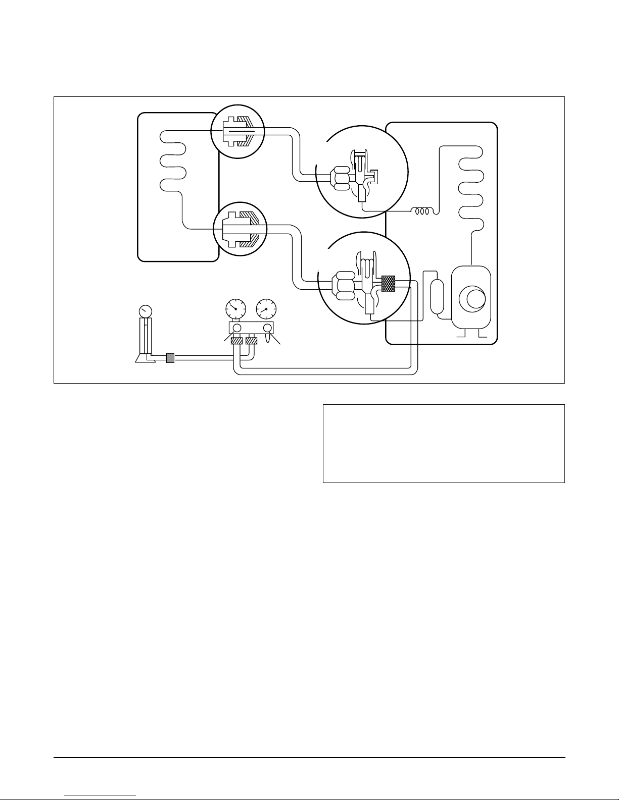
3. Gas Charging
(After Evacuation)
• Procedure
(1) Connect the charge hose to the charging
cylinder.
– Connect the charge hose which you dis-con-
nected from the vacuum pump to the valve at
the bottom of the cylinder.
– If you are using a gas cylinder, also use a scale
and reverse the cylinder so that the system can
be charged in liquid state.
(2) Purge the air from the charge hose.
– Open the valve at the bottom of the cylinder
and press the check valve on the charge set to
purge the air. (Be careful of the liquid refrigerant). The procedure is the same if using a gas
cylinder.
(3) Open the valve (Lo side on the charge set and
charge the system with liquid refrigerant.
– If the system can not be charged with the spec-
ified amount of refrigerant, it can be charged
with a little at a time (approximately 150g each
time) while operating the air conditioner in the
cooling cycle; however, one time is not sufficient, wait approximately 1 minute and then
repeat the procedure.
(4) Immediately disconnect the charge hose from
the 3-way valve’s service port.
– Stopping partway will allow the gas to be dis-
charged.
– If the system has been charged with liquid
refrigerant while operating the air conditioner,
turn off the air conditioner before disconnecting
the hose.
(5) Mount the valve stem nuts and the service
port nut.
– Use torque wrench to tighten the service port
nut to a torque of 1.8 kg.m.
– Be sure to check for gas leakage.
\
This is different from previous procedures.
Because you are charging with liquid refrigerant
from the gas side, absolutely do not attempt to
charge with larger amounts of liquid refrigerant
while operating the air conditioner.
Lo
Charging
cylinder
Outdoor unit
Indoor unit
Liquid side
Gas side
CLOSE
Open
2-Way
valve
3-Way
valve
OPEN
Open
Check valve
(1)
Page 42
- 42 -
Copyright ©2008 LG Electronics. Inc. All right reserved.
Only for training and service purposes
LGE Internal Use Only
Cycle Troubleshooting Guide
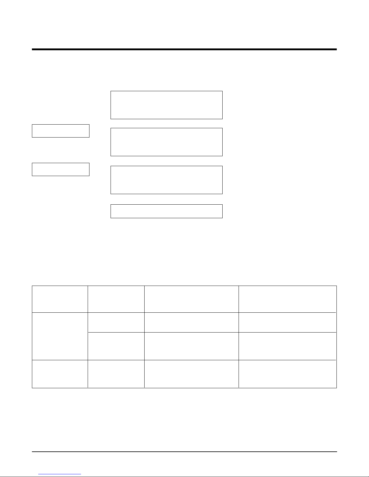
Trouble analysis
1. Check temperature difference between intake and discharge air and operating current.
Temp. Difference
Temp. difference : approx. 0°C
Current : less than 80% of
rated current
Temp. difference : approx. 8°C
Current : less than 80% of
rated current
Temp. difference : less than 8°C
Current : over the rated
current
Temp. difference : over 8°C
Operating Current
All amount of refrigerant leaked out
Check refrigeration cycle
Refrigerant leakege
Clog of refrigeration cycle
Defective compressor
Excessive amount of refrigerant
Normal
Notice :
Temperature difference between intake and discharge air depends on room air humidity. When the room air
humidity is relativery higher, temperature difference is smaller. When the room air humidity is relatively lower temperature difference is larger.
2. Check temperature and pressure of refrigeration cycle.
Notice :
1. The suction pressure is usually 4.5~6.0 kg/cm2G at normal condition.
2. The temperature can be measured by attaching the thermometer to the low pressure tubing and wrap it with
putty.
Suction pressure Temperature
(Compared with (Compared with Cause of Trouble Description
the normal value) the normal value)
Defective compressor Current is low
Defective 4-way reverse valve
Excessive amount of High pressure does not quickly
Normal refrigerant rise at the beginning of
operation
Insufficient amount of Current is low
Lower Higher refrigerant (Leakage)
Clogging Current is low
High
Higher
Page 43
- 43 -
Copyright ©2008 LG Electronics. Inc. All right reserved.
Only for training and service purposes
LGE Internal Use Only
Electronic Parts Troubleshooting Guide
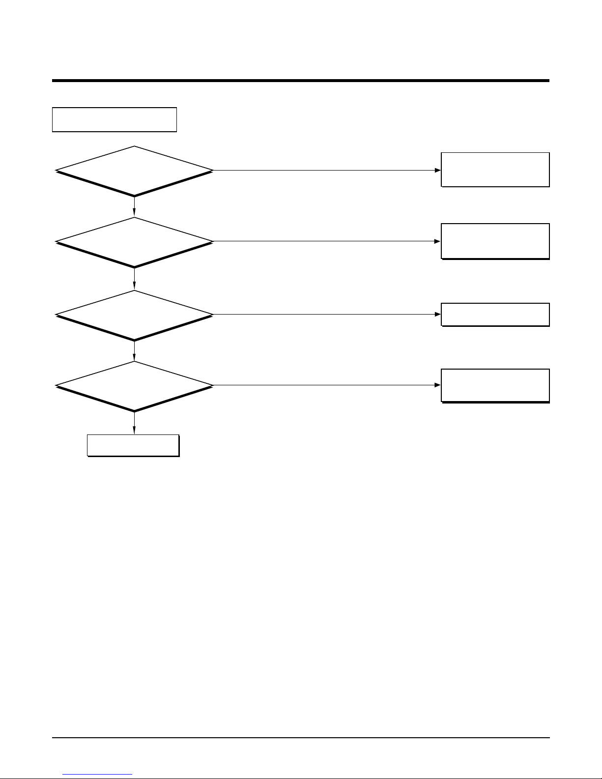
: The unit does not operate.
Possible Trouble 1
YES
NO
YES
Is the input voltage
AC230V?
Check the FUSE
and the wiring diagram.
Is the PIN 49,58 of
MICOM. DC5V?
Exchange MICOM.
YES
NO
Check the main P.C.B
pattern.
NO
YES
Is the output voltage
of IC03D DC5V?
NO
Exchange
IC03D
.
Is the input voltage
of IC03D about DC12V?
Check the
5V P.C.B pattern.
Page 44
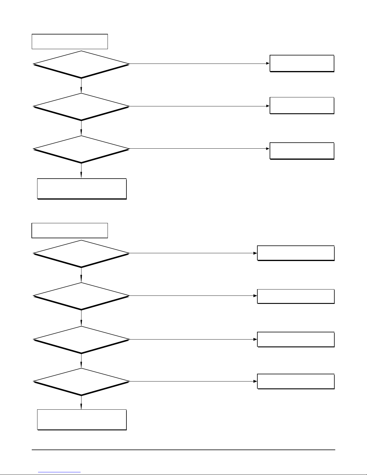
- 44 -
Copyright ©2008 LG Electronics. Inc. All right reserved.
Only for training and service purposes
LGE Internal Use Only
Possible Trouble 2
: The indoor fan does not operate.
NO
NO
Is it the HOT
START mode?
Is IC01M operated
normally?
Check the fan motor
and connector.(CN-MOTOR)
YES
Is the each Relay
any problem?
YES
NO
YES
It is normal operation.
Exchange IC01M.
Exchange Relay.
YES
YES
NO
YES
Is it Heating Mode?
Does the temperature
set all right?
Change IC01M.
NO
NO
Adjust operation mode.
Adjust set temperature.
Is IC01M operated
normally?
YES
Check the connector.
(CN-OUT)
Check RY-4Way.
NO
Is 4way-valve operated?
Possible Trouble 3
: Ineffective Heating
Page 45
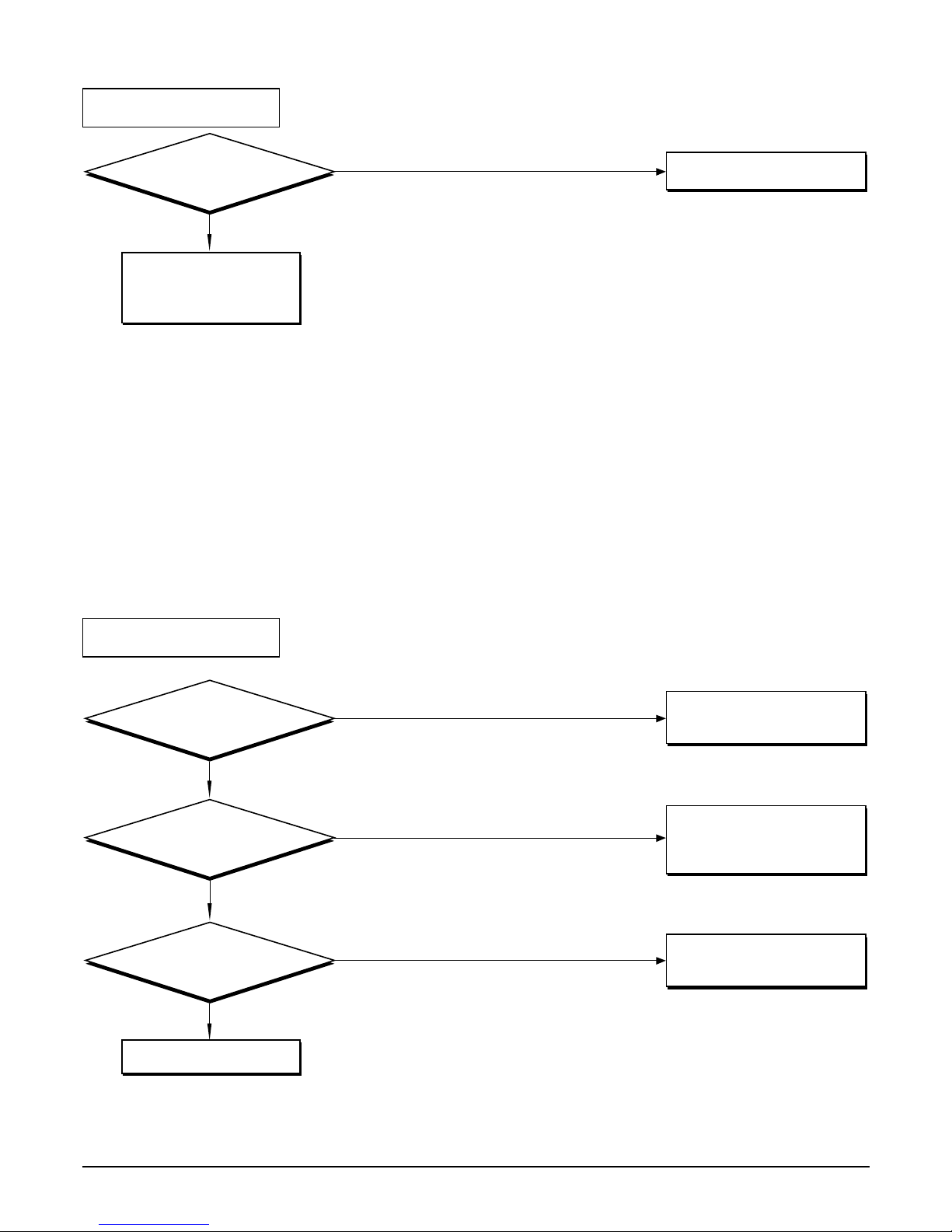
- 45 -
Copyright ©2008 LG Electronics. Inc. All right reserved.
Only for training and service purposes
LGE Internal Use Only
Possible Trouble 4
: Auto Air direction louver does not operate.
Possible Trouble 5
: Wired remote controller does not operate.
YES
NO
Is IC01M operated
normally?
Check the motor and
connector.
(CN-LOUVER)
Exchange IC01M.
NO
YES
YES
YES
Is the LCD operated
normally?
Is the terminal of wired
Remocon T2 DC12V?
Is the pin 39, 40 of
Micom DC 5V?
Change the wired Remocon.
Check the wired Remocon
PCB and DC 12V pattern.
NO
NO
Check the parts of
communication.
Connector CN-Remo, and
terminals of wired
Remocon exactly.
Page 46
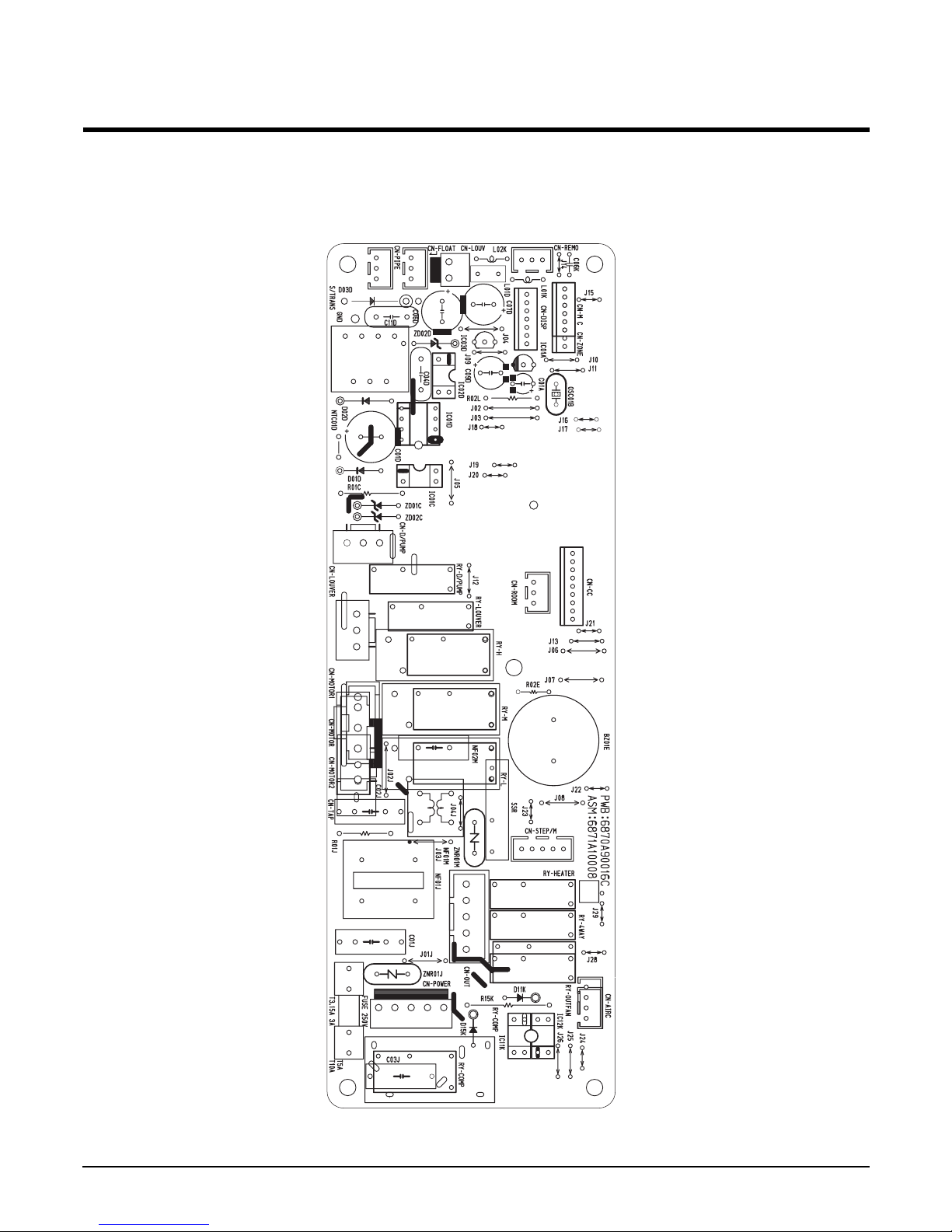
- 46 -
Copyright ©2008 LG Electronics. Inc. All right reserved.
Only for training and service purposes
LGE Internal Use Only
Electronic control device
■ MAIN P.C.B ASM
Page 47
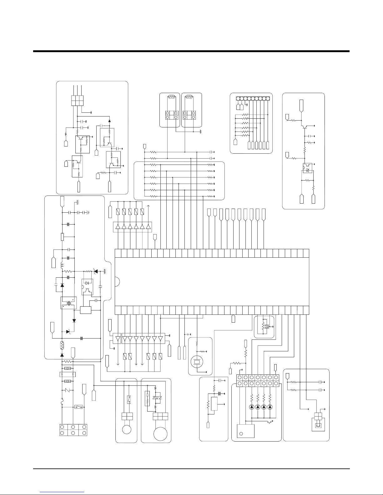
- 47 -
Copyright ©2008 LG Electronics. Inc. All right reserved.
Only for training and service purposes
LGE Internal Use Only
P20(INT5/STOP)
P12(INT2/TC1)
22
11
Force
SW
P32
LOUVER
FLOAT
LED4
P35
P33
P34
8.00MHZ
OSC01B
XIN
LED1
LED2
LED3
XOUT
P30
P31
XIN
XOUT
VSS
NC
RESET
NC
GND
P21(XTIN)
P22(XTOUT)
RESET
TEST
KIA7036P
1
33
22
11
2
3
3
1
3
1
PHASE
FREQ
REMO
P15(TC2)
P17
P16
P13(DVO)
P14(PPG)
P11(INT1)
P10(INT0)
P05
P06
P07
STEP M3
STEP M2
D/PUMP
LOUVER
MED
STEP M5
HIGH
LOW
P03
P04
P02
P00
P01
P77
P76
NC
NCNCNC
CC TX
CC RX
SB0
SB2
SB1
(SI1)/P43
(SCK)/P42
(SI2)/P46
(SCK2)/P45
(SO1)/P44
(INT4/TC4)/P51
(INT3/TC3)/P50
(SO2)/P47
(PWM/PDO)/P52
P53
RX
(AIN7)/P67
SB3
OPTION 1
ROOM TH
PIPE TH
OPTION2
OPTION3
OPTION4
OPTION5
(AIN2)/P62
(AIN1)/P61
(AIN0)/P60
VARF
VASS
P54
(AIN4)/P64
(AIN6)/P66
(AIN5)/P65
(AIN3)/P63
OPTION6
STEP M4
COMP
A/C
HEATER
4WAY
OUTFAN
P71
P70
VDD
P73
P72
P74
P75
TX
TX
RX
CN-REMO
132
132
C06D
C04D
103/250VA
470uF/35V
IC02D(TLP521)
C05D
681
5V
DISPLAY
TFMS-2380B
PRE AMP
LED2
LED3
LED4
Vout
GND
Vcc
LED1
77
4
5
6
4
5
6
1 1
2
3
2
3
5V
293230
31
REMO
262728
24
25
212223
20
19
3,7,8
NF01M
5V
+
ZNR01M
NF01M
SSR
8
KID65004AF
IC01M
DC 12V
50/60Hz
REMO
13
18
17
161415
111210
9
DC 12V
STEP M
STEP M
STEP M
DC 12V
KID65004AF
IC02M
576
4
3
103
2
1
1M,1/2W
275V
C02J
100nF
3
1
3
1
2 2
M_RTX
AC_L
275V
C01J
100nF
3 4
NF
INR14D561K
ZNR01J
T3.15A,3A
250V/
22mH/3A
12
NF01J
P6KE200A
ZD01D
DC310V
NTC01D
400V
10uF/
C01D
10D-9
AC_N
1N4007
R01J
D01D
D03D
C03D
UF4005
TNY255P
IC01D
4
1
S
2
255P
TNY
5
D02D
D
3
EN
BP
4,5
UF5402
S/Trans
1
6,7
363335
34
393837
41
40
444342
46
45
CN-ROOM
CN-PIPE
ZD02D
57
52
474948
51
50
54
53
56
55
605958
62
61
11V
63
64
STEP M
KID65004AF
IC02M
DC 12V
1 13 3
C08D
104
3.3uH
R03D
R04D
150
39
330uF/35V
C07D
L01D
12V
223/1KV
103/1KV
G
C12D
C11D
C10D
103
C09D
220uF/50V
KID78L05BP
7805
IC03D
I O
5V
CN-CC
1 13 3
9
8
7
6
4
5
3
1
2
NF02M
C01A
3.6V
CN-DISP
5V
CN-FLOAT
C02F
103
1K
R02F
C01F
103
1K
R01F
R04L
1K
R06L
R05L
1K
1K
102
R03L
1K
/50V
3.3uF
R01B
1.0M
R02L
1K
R01L
10K
IC01A
R02A
MOTOR
FAN
CN-MOTOR2
C02A
R01A 1K
10K
CN-D/PUMP
Motor
Drain
RY-D/PUMP
C02L
BZ01E
1K
R01E
R02E
20
681
NEUTRAL
RY-COMP
SIGNAL
CN-POWER
LIVE
RX
TX
S_B0TXRX
S_B2
S_B1
1K
AC_N
200K/2W
R01C
AC_L
R02C
102
C01K
R01K
1K
5V
C01C
R05C
103
1K
DAN212K
102
C03K
KRC104M
10K
R03C
IC01C
5V
4.7K
R04C
C02K
Q02K
102
12V
KRA104M
Q04K
Q01C
10K
5V
R06C
50/60Hz
D02K
S_B3
GND
5V
5V
OR1OR4OR6 OR5 OR2OR3 C01H
103
C02H
103
R03H
12.1K
R08H
12.1K
1%
R07H
12.1K
1%
R06H
12.1K
1%
R04H
12.1K
1%
R05H
12.1K
1% 1%
5V
R02H
6.2K
1%
R01H
12.1K
1%
KRA104M
Q01K
5V
10K*6
R01T
R06T
R02T
R03T
R04T
R05T
S_B3
S_B2
S B1
1/10W
S B0
5V
103
C06K
C05K
100nH
12V
KRC104M
Q03K
4.7K
C04K
104
R02K
L01K
GND
Signal
DC12V
12V
5V
Schematic Digram
Page 48
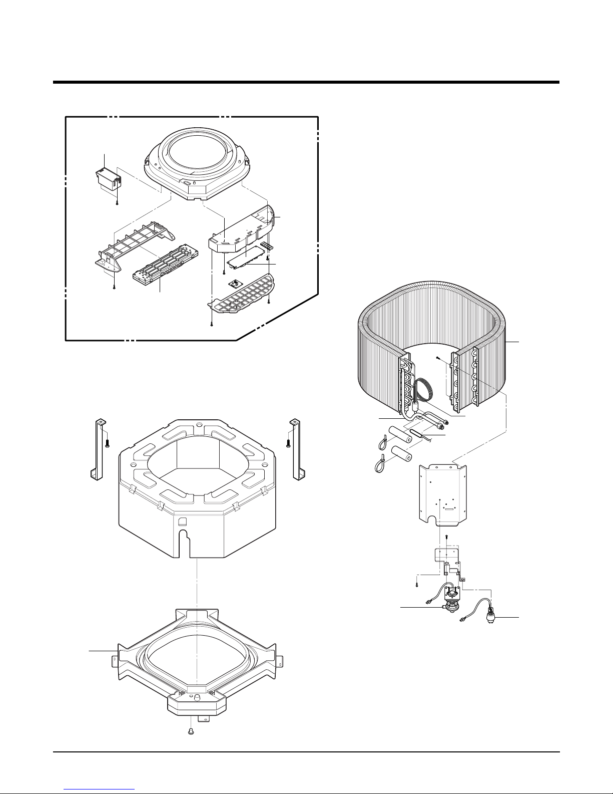
- 48 -
Copyright ©2008 LG Electronics. Inc. All right reserved.
Only for training and service purposes
LGE Internal Use Only
Exploded View
1. Indoor Unit
354212
249951
266090
268711B
266010
35211A
263230A
352118
330870
158591
159830
Page 49
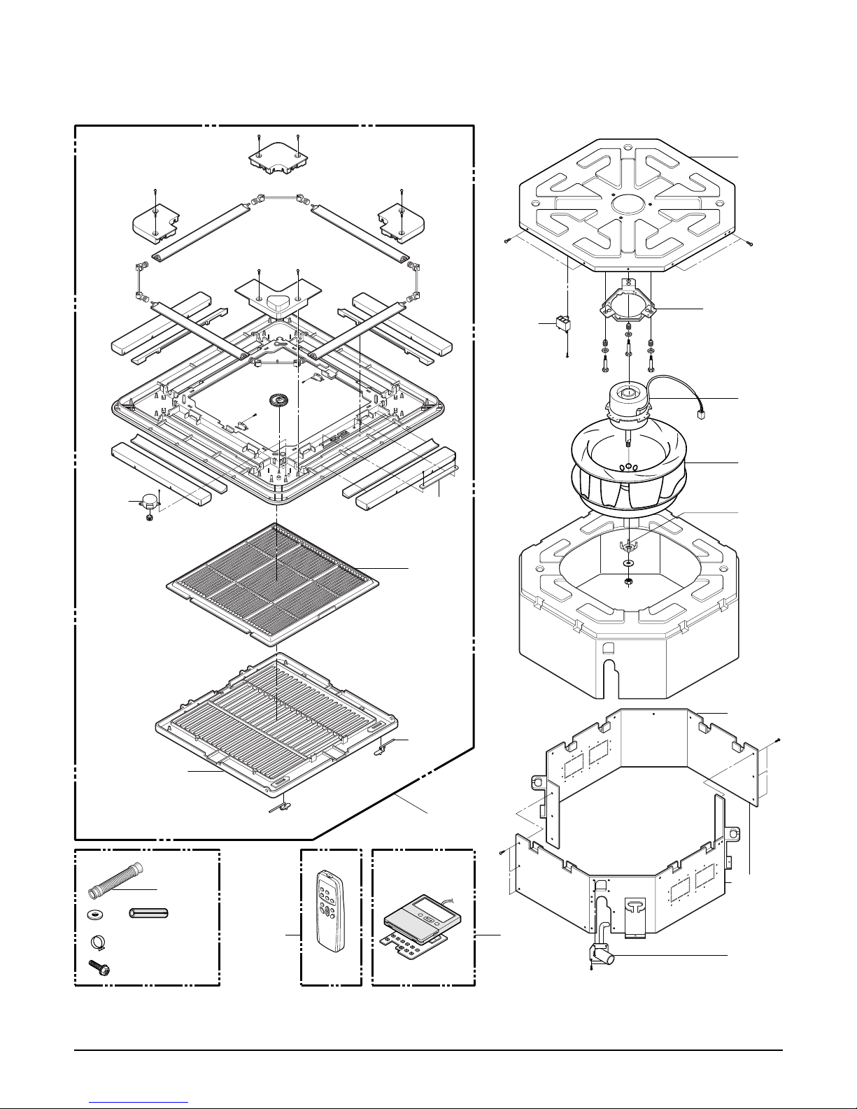
- 49 -
Copyright ©2008 LG Electronics. Inc. All right reserved.
Only for training and service purposes
LGE Internal Use Only
346810
130411
349600
359012
152312
135800
135303
W0CZZA
137211
267110B267110A
352150A
352150B
130911B
130911A
140570
268711A
146811
Accessory : Front Panel
Accessory
Option
Page 50
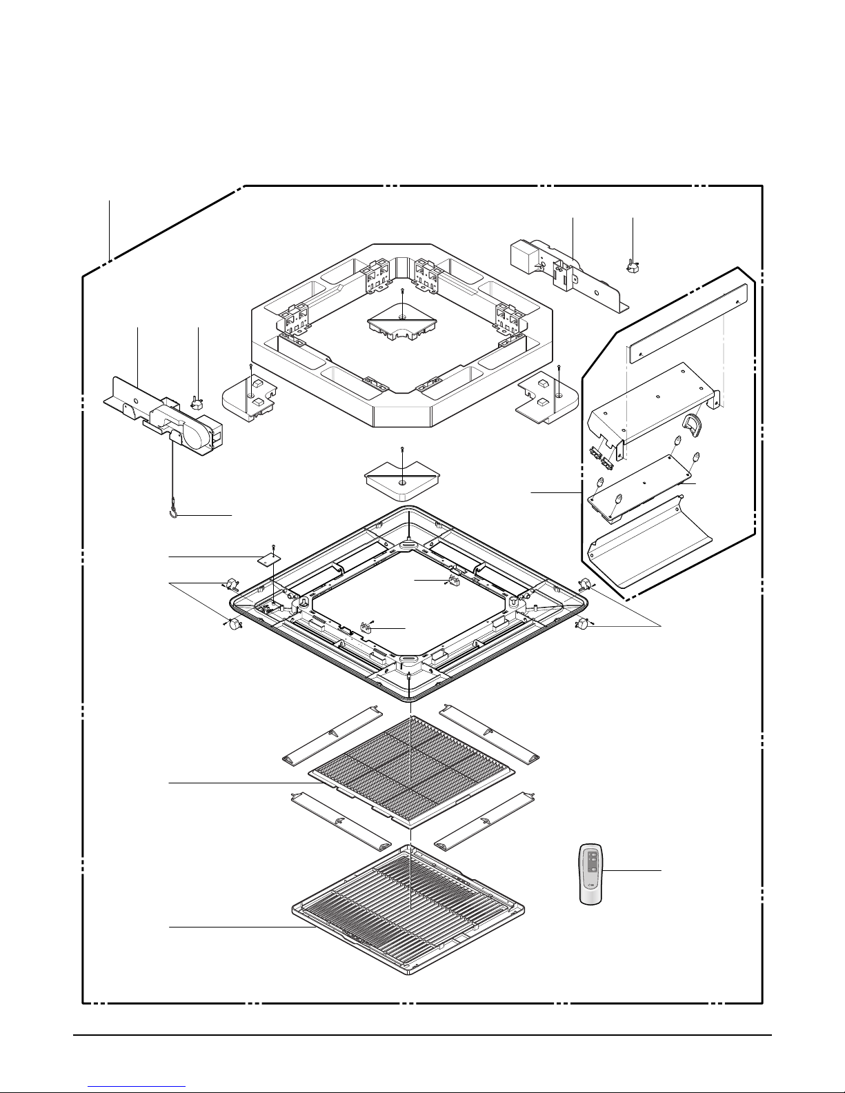
- 50 -
Copyright ©2008 LG Electronics. Inc. All right reserved.
Only for training and service purposes
LGE Internal Use Only
137211
W4811-2 146812-2
146812-1W4811-1
435310
152312
268712
668713
249951
146811
146811
267110
750830
266011-2
266011-2
Elevation Grille
Page 51
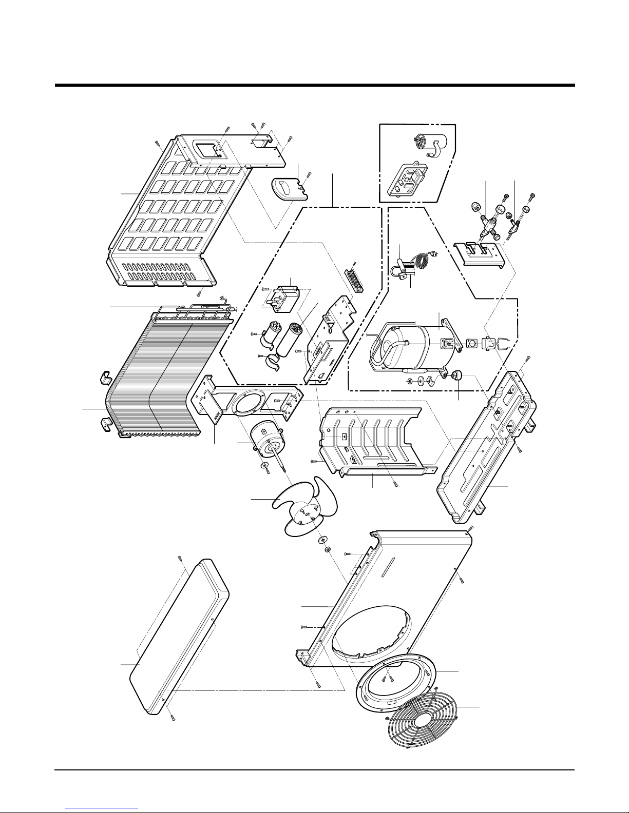
- 51 -
Copyright ©2008 LG Electronics. Inc. All right reserved.
Only for training and service purposes
LGE Internal Use Only
2. Outdoor Unit
435512
546810
549610
554160
552203A
649950
435511
W6920
552202
561410
W0CZZB
552203B
447910
550140
559010
430411
435301
349480
437212
437210
552113
554031
Page 52

P/NO : 3828A20048D
JUNE, 2008
 Loading...