

LG LTD-VL1110 User Manual

Copyright ⓒ. 2014. All Rights Reserved.
User Guide for LTD-VL1110 (Eagle)
1. Overview
2. Major feature
3. Interface
4. Electrical specification
5. RF specification
6. Mechanical specification
7. General specification
8. Connector
9. RFx information
10. FCC Approval
Table of Contents
Product : LTE/CDMA(EVDO) Wireless Modem
Model name : LTD-VL1110
Copyright ⓒ. 2014. All Rights Reserved.
The LTD-VL1110 is achieved as personal mobile communication devices of
the compact radio equipment, the latest design of the parts becoming smaller,
lighter weight having the LTE(700/1700MHz), CDMA(850/1900MHz) bands. It is
the vehicle’s telematics system that connect with LTE and CDMA(EVDO)
wireless network and the wireless module with voice and data communication. It
can be operated at land, rivers, and other similar areas.
On LTE operating mode, It can be communicated with uplink 50Mbps, downlink
up to 100Mbps data transfer speed such as a movie or a video call. It may be
able to receive large amounts of data.
Standard RS-232 port and USB port communicating with the host system via
AT-command or control commands can be used to send data. Voice calls are
possible.
1. Overview
Copyright ⓒ. 2014. All Rights Reserved.
Mechanical
Dimension
93.15(L) x 45.0(W) x 7.6(T) mm
Weight
45g(max)
Interface
USB, UART, General Purpose I/O pins
Antenna
FAKRA Connector
Temperature *
Operation : -20℃ ~ +70 ℃
Storage : -40 ℃ ~ +85 ℃
Technology
Main Chipset
MDM 9615
Memory
2048Mb(NAND) / 1024Mb(SDRAM)
Standard
3GPP Rel.8 LTE Cat.3
- DL Speed : 100 Mbps(20M bandwidth)
- UL Speed : 50 Mbps(20M bandwidth)
3GPP2 CDMA 1X, EVDO Rev.A
- DL Speed : 3.1 Mbps
- UL Speed : 1.8 Mbps
Band
LTE B4, B13
CDMA 850(Cellular), 1900 (PCS)
GPS Not Supported
Power
LTE : Typ. 23dBm(Power Class 3)
CDMA : Typ. 24dBm (Power Class 3)
ETC
DC Power
3.8V
Functions
Voice, Data, SMS
2. Major feature
Copyright ⓒ. 2014. All Rights Reserved.
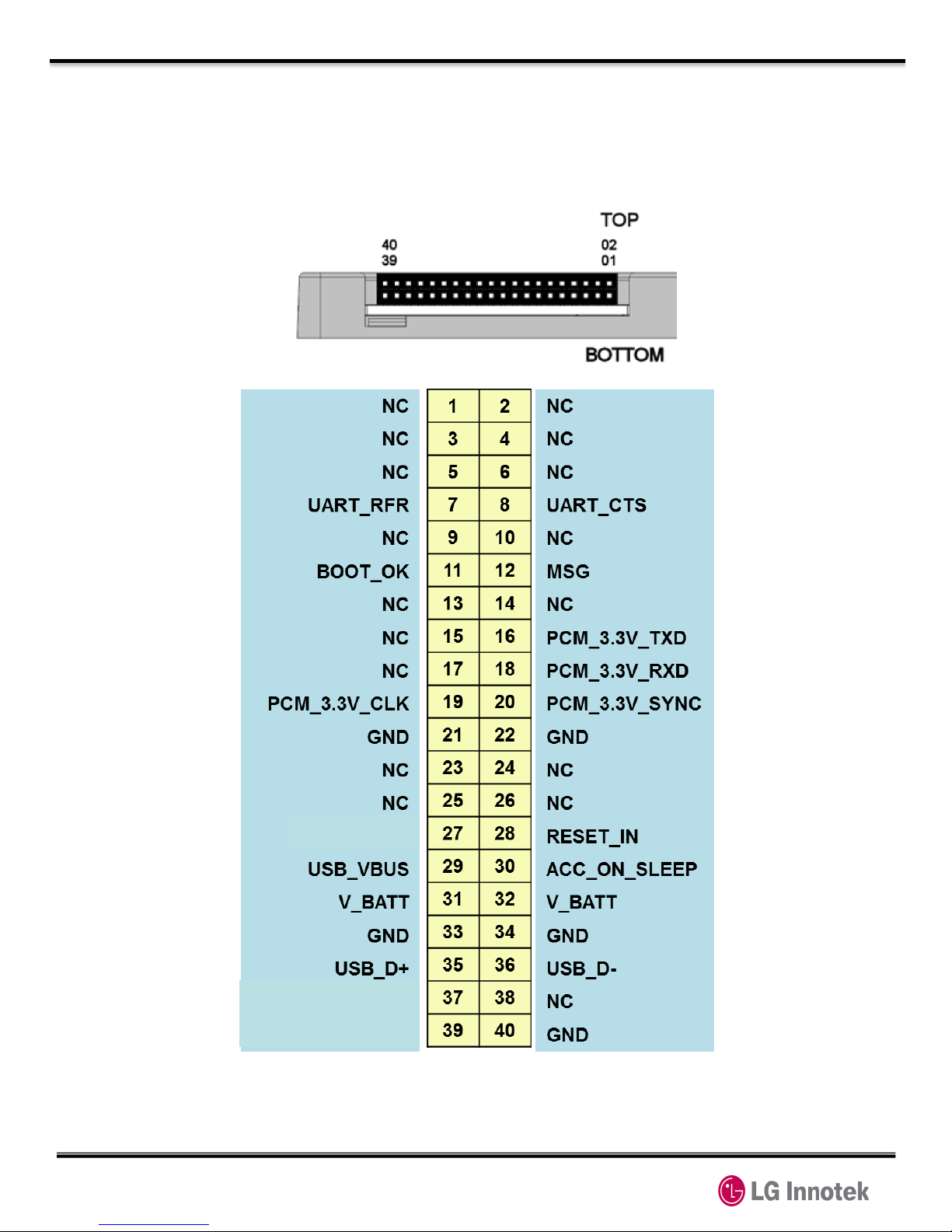
3. Interface
Customer P/N is connected with outer device using 40 pin connector
3.1 Pin output
Figure 1. Connector pin arrangement
48H_END
UART_TX_TCU
UART_RX_TCU
Copyright ⓒ. 2014. All Rights Reserved.
3. Interface
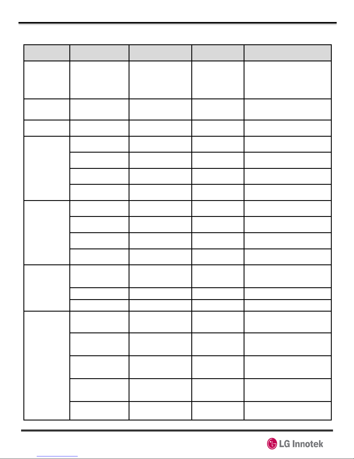
3.2 Pin description
Pin NO. Signal Name In/Out Function
NC
1, 2, 3, 4, 5, 6, 9,
10, 13, 14, 15, 17
, 23, 24, 25, 26, 3
8
NC
V_BATT
31, 32 POWER POWER
GND 21, 22, 33, 34, 40
GND GND
Audio
PCM
16 PCM_3.3V_TXD O PCM DATA OUT
18 PCM_3.3V_RXD I PCM DATA IN
19 PCM_3.3V_CLK I PCM CLK
20 PCM_3.3V_SYNC
I PCM SYNC
UART2
(DM Port)
37 UART_RXD I UART RX DATA
39 UART_TXD O UART TX DATA
7 UART_RFR O UART ready-for-receive
8 UART_CTS I UART clear-to-send
USB
(USB2.0)
29 USB_VBUS I
Power supply for the
USB transceiver
35 USB_D+ I/O USB differential data (+)
36 USB_D- I/O USB differential data (-)
User Interface
11 BOOT_OK O
Modem Booting Completion
/ Modem Wake Up
12 MSG O
Received emergency
message from Center
27 96H_END O
Signified in 96 hours
standby mode ending
28 RESET_IN I
Modem Hardware reset
input
30 ACC_ON_SLEEP
I
Modem Power ON
/ Modem POWER Sleep
Table 1. Pin descriptions
Copyright ⓒ. 2014. All Rights Reserved.
3. Interface
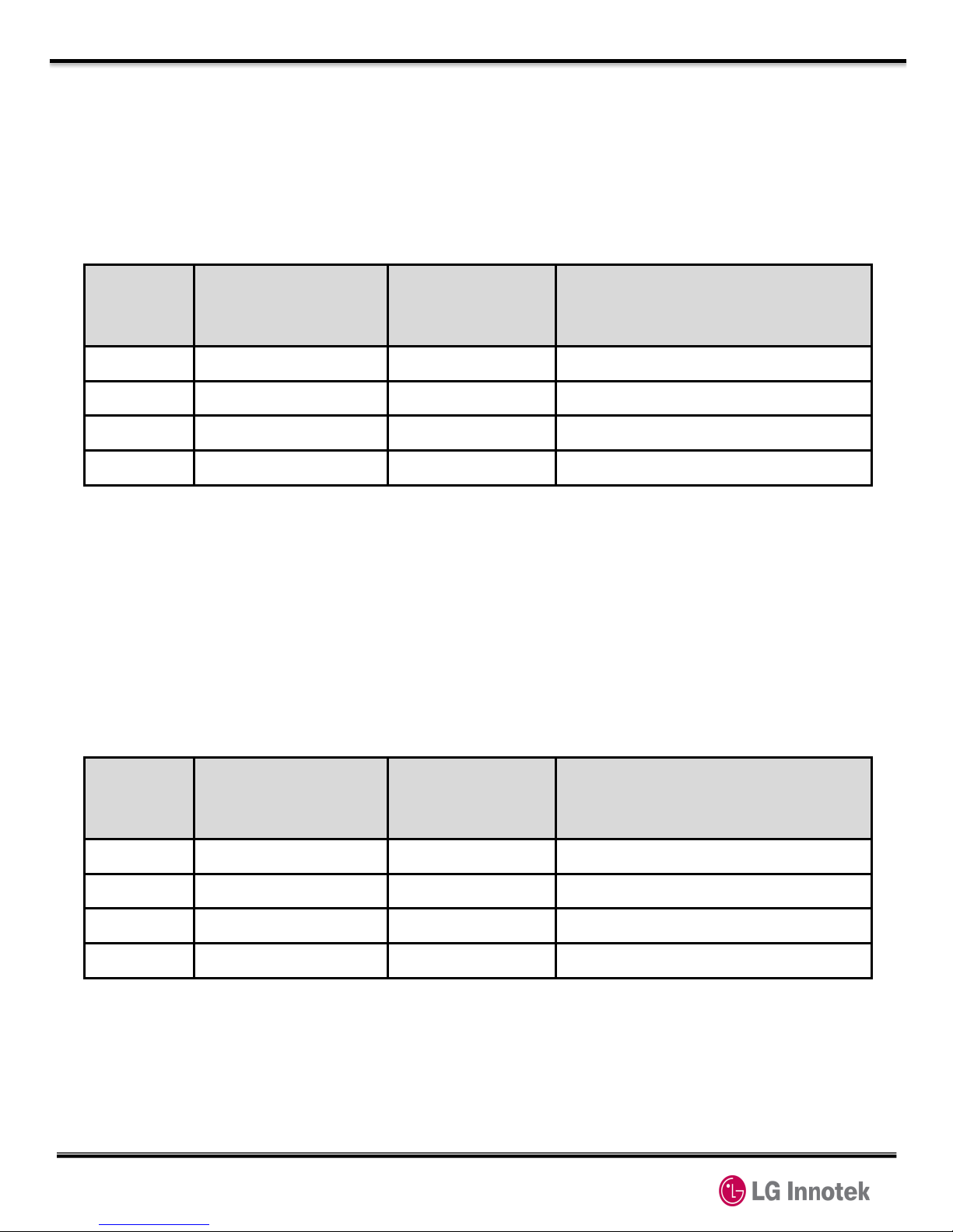
3.3 UART(RS-232 Interface)
This module is provided with interface supporting Standard RS-232 protocol.
DCE(modem) communicate with DTE(host) through data or control ATCommand.
Pin No. Signal Name Direction Function
37 UART_RXD I UART RX DATA
39 UART_TXD O UART TX DATA
7 UART_RFR O UART ready-for-receive
8 UART_CTS I UART clear-to-send
3.4 USB
It is supported with universal serial bus for high data communication. And It
is satisfied with USB2.0 specification and supported with max.480Mbps
Pin No. Signal Name Direction Function
37 UART_RXD I UART RX DATA
39 UART_TXD O UART TX DATA
7 UART_RFR O UART ready-for-receive
8 UART_CTS I UART clear-to-send
Table 2. UART Pin descriptions
Table 3. USB Pin descriptions
 Loading...