

Page 1

OWNER’S MANUAL
AIR
CONDITIONER
Please read this manual carefully before operating
your set and retain it for future reference.
NORSK SUOMI DANSK
TYPE : Through the Wall
MODELS LT1037HNR LT1237HNR
P/NO : MFL68744002
Rev.02_113017
Copyright © 2016 - 2017 LG Electronics Inc. Todos los derechos reservados.
Copyright © 2016 - 2017 LG Electronics Inc. All Rights Reserved.
www.lg.com
Page 2
2 Room Air Conditioner
Window-Type Air Conditioner Owner’s Manual
TABLE OF CONTENTS
FOR YOUR RECORDS
Write the model and serial numbers here:
Model #
Serial #
You can find them on a label on the side of each unit.
Dealer's Name
Date Purchased
■ Staple your receipt to this page in the event you need it
to prove date of purchase or for warranty issues.
READ THIS MANUAL
Inside you will find many helpful hints on how to use and
maintain your air conditioner properly. Just a little preventive
care on your part can save you a great deal of time and
money over the life of your air conditioner.
You'll find many answers to common problems in the chart
of troubleshooting tips. If you review our chart of
Troubleshooting Tips first,youmaynotneedtocallfor
service at all.
PRECAUTION
• Contact the authorized service technician for repair
or maintenance of this unit.
• Contact the installer for installation of this unit.
• The air conditioner is not intended for use by young
children or invalids without supervision.
• Young children should be supervised to ensure that
they do not play with the air conditioner.
• When the power cord is to be replaced, replacement
work shall be performed by authorized personnel only
using only genuine replacement parts.
• Installation work must be performed in accordance
with the National Electric Code by qualified and
authorized personnel only.
Safety Precautions..........................3
Before Operation.............................7
Introduction ....................................8
Electrical Safety ..............................9
Installation ....................................11
Operating Instructions .................18
Maintenance and Service ............21
Page 3
Safety Precautions
WARNING
Gasolin
Safety Precautions
To prevent injury to the user or other people and property damage, the following instructions
must be followed.
Incorrect operation due to ignoring instruction will cause harm or damage. The seriousness
is classified by the following indications.
WARNING
CAUTION
Meanings of symbols used in this manual are as shown below.
Installation
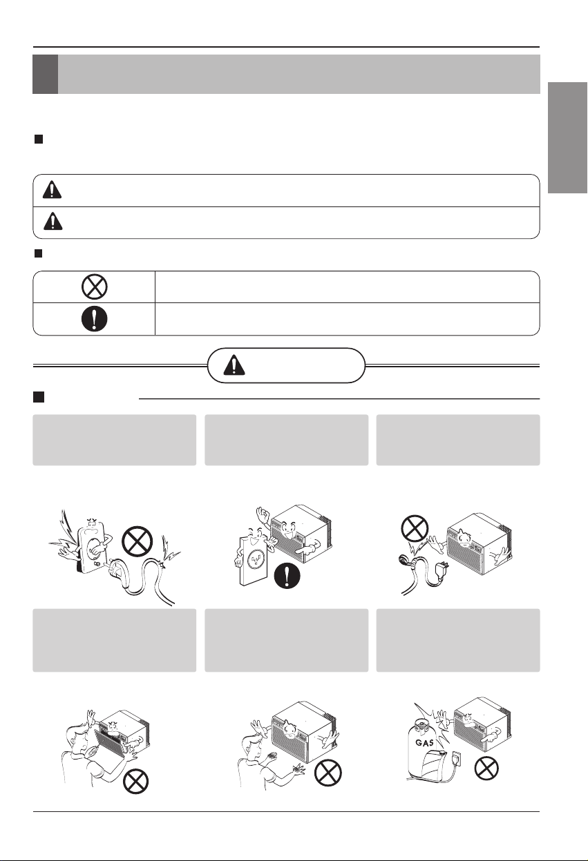
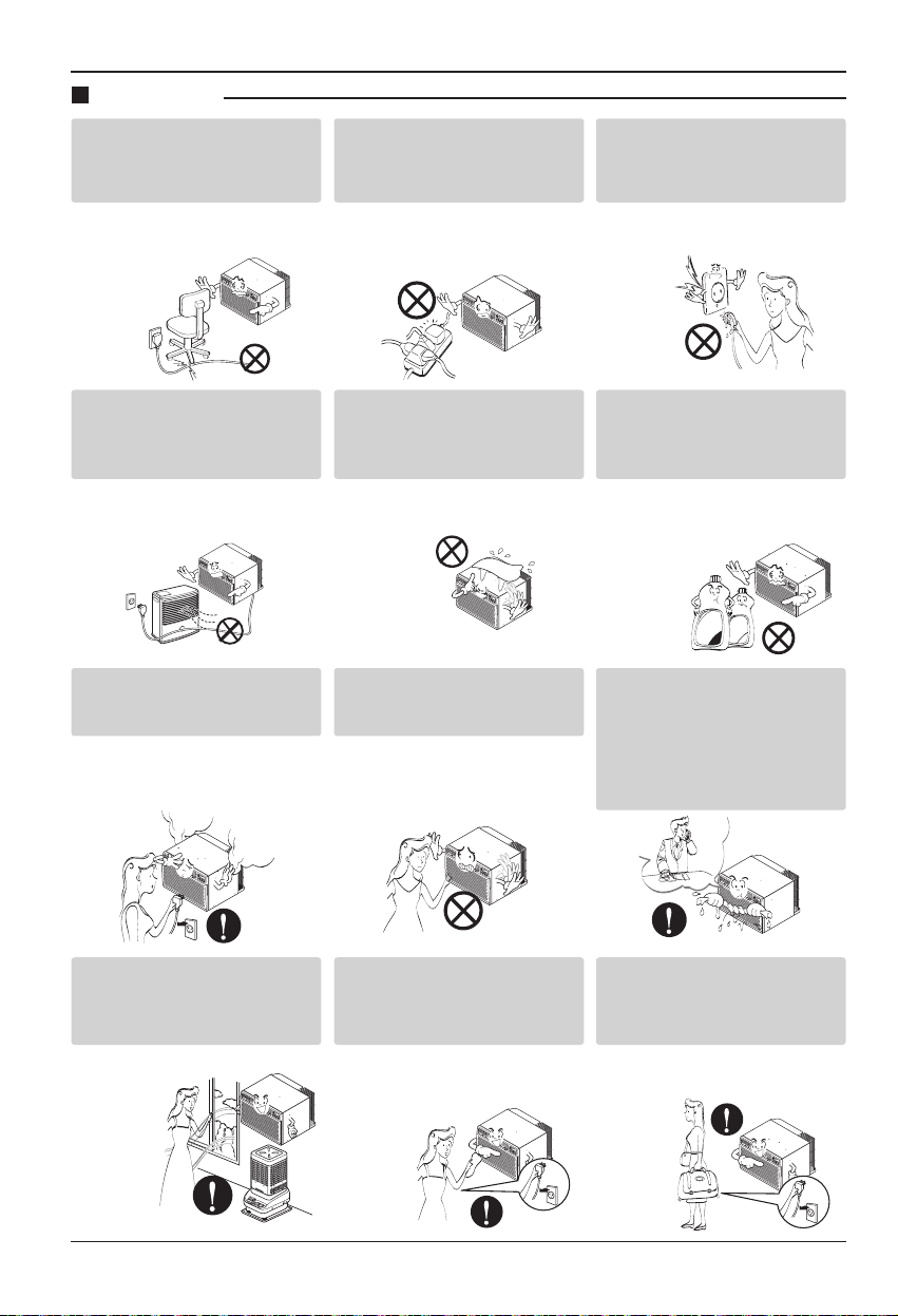
Don’t use a power cord, a
plug, or a loose socket
which is damaged.
• Otherwise, it may cause a fire
or electrical shock.
This symbol indicates the possibility of death or serious injury.
This symbol indicates the possibility of injury or damage to properties only.
Be sure not to do.
Be sure to follow the instruction.
Always plug into a grounded
Always plug into a grounded
outlet.
outlet.
• Otherwise, it may cause a fire
or electrical shock.
Do not modify or extend the
Do not modify or extend the
power cord length.
power cord length.
• It will cause electric shock or fire
due to heat generation.
ENGLISH
Do not disassemble or
modify products.
• It may cause failure and
electric shock.
Be caution when unpacking
and installing.
• Sharp edges may cause
injury.
Do not store flammables like
gasoline, benzene, thinner, etc.
near the air conditioner.
• It may cause explosion or fire.
Owner’s Manual 3
Page 4
Wax
Thinner
Safety Precautions
Operation
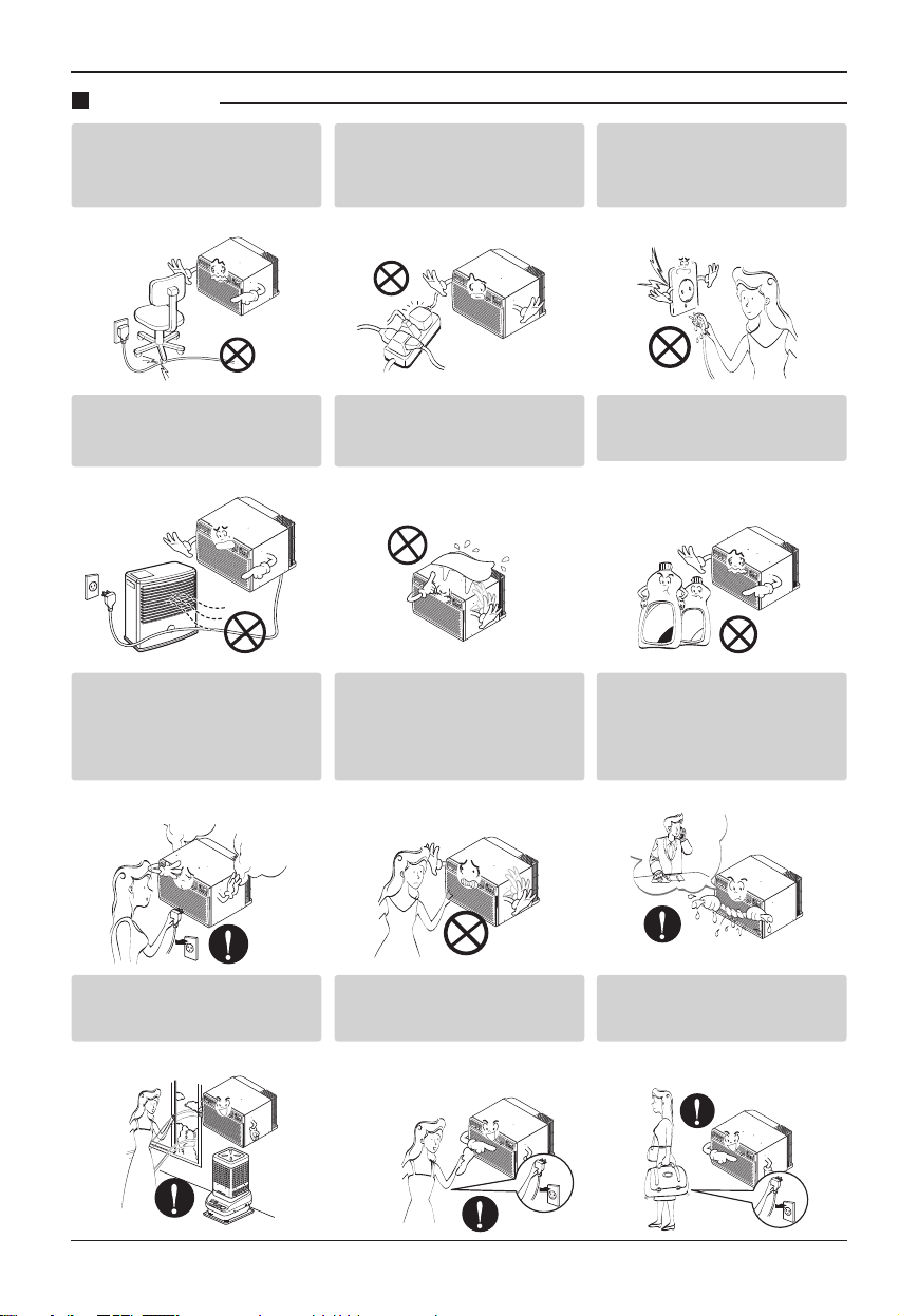
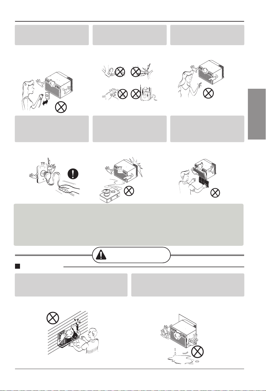
Do not place heavy object
on the power cord and take
care so that the cord should
not be pressed.
• There is danger of fire or electric
shock.
Do not share the outlet with
other appliances.
• It will cause electric shock or fire
due to heat generation.
Take the power plug out if
necessary, holding the head
of the plug and do not touch
it with wet hands.
• Otherwise, it may cause a fire
or electrical shock.
Do not place the power cord
near a heater.
• It may cause fire and electric
shock.
Unplug the unit if strange
sounds, odors, or smoke
come from it.
• Otherwise it may cause fire and
electric shock accident.
No correlation between fan
usage and oxygen depletion.
• An oxygen shortage may occur.
Do not allow water to run
into electric parts.
• It will cause failure of machine or
electric shock.
Do not open the suction
inlet grill of the product
during operation.
• Otherwise, it may electrical
shock and failure.
Turn off the power and
breaker first when cleansing
the unit.
• Since the fan rotates at high
speed during operation, it may
cause injury.
Use a soft cloth to clean. Do
not use wax, thinner, or a
strong detergent.
• The appearance of the air
conditioner may deteriorate,
change color, or develop surface
flaws.
If water enters the product, turn
off the the power switch of the
main body of appliance. Contact
service center after taking the
power-plug out from the socket.
Unplug the unit when not
using it for a long time.
• Prevent accidental startup and
the possibility of injury.
4 Room Air Conditioner
Page 5
Owner’s Manual 5
ENGLISH
Safety Precautions
CAUTION
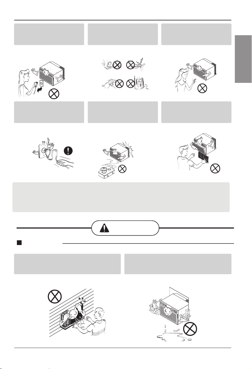
Do not operate or stop the
unit by inserting or pulling
out the power plug.
• It will cause electric shock or fire
due to heat generation.
Hold the plug by the head
when taking it out.
• It may cause electric shock and
damage.
Do not damage or use an
unspecified power cord.
• It will cause electric shock or fire.
When gas leaks, open the
window for ventilation
before operating the unit.
• Otherwise, it may cause
explosion, and a fire.
Do not operate with wet
hands or in damp
environment.
• It will cause electric shock.
Never touch the metal parts
of the unit when removing
the filter.
• They are sharp and may cause
injury.
For inner cleaning, contact an Authorized Service Center or a dealer.
Do not use harsh detergent that causes corrosion or damage on the unit.
Harsh detergent may also cause failure of product, fire, or electric shock.
Installation
Install the product so the exhaust and noise
are not aimed directly at the neighbors.
• Be considerate.
Follow installation instructions exactly.
• Otherwise, it may cause vibration or water
leakage.
Page 6
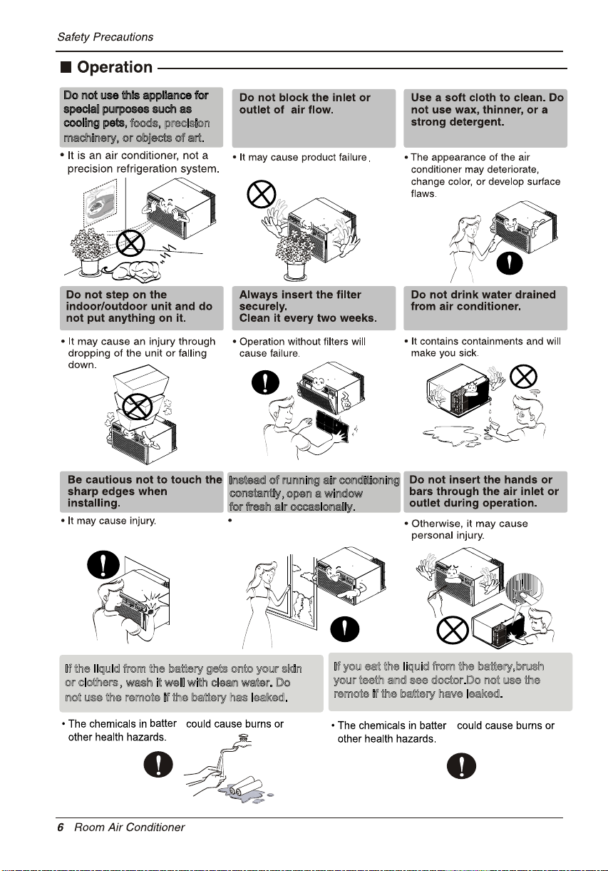
Do not use this appliance for
special purposes such as
cooling pets,
foods, precision
machinery, or objects of art.
Instead of running air conditioning
constantly
,open a window
for fresh air occasionally.
You will feel better.
If the liquid from the battery gets onto your skin
or clothers,
wash it well with clean water. Do
not use the remote if the battery has leaked.
y
If you eat the liquid from the battery,brush
your teeth and see doctor.Do not use the
remote if the battery have leaked.
y
Page 7
2. No correlation between fan usage and oxygen depletion.
3.
7
Page 8
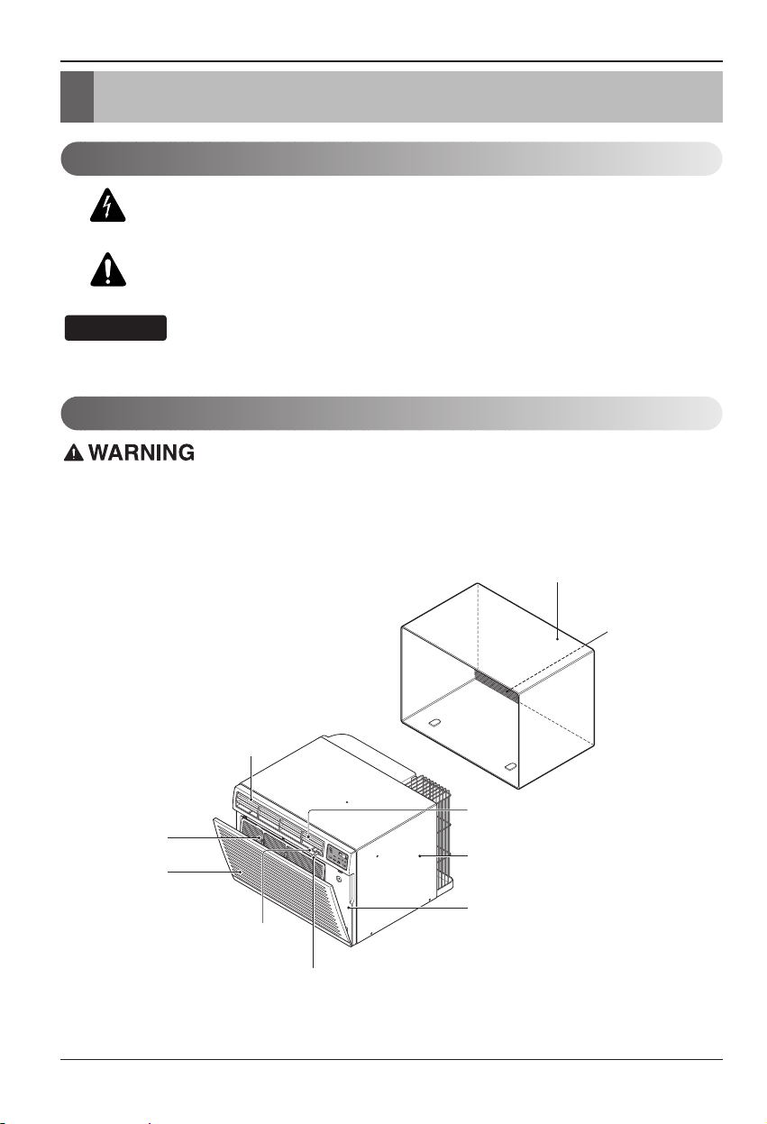
8 Room Air Conditioner
Introduction
This symbol alerts you to the risk of electric shock.
This symbol alerts you to hazards that could cause harm to
the air conditioner.
This symbol indicates special notes.
NOTICE
This appliance should be installed in accordance with the National Electric Code.
Introduction
Symbols Used in this Manual
Features
THE SLEEVE AND THE REAR GRILLE
(optionally supplied with your unit)
SLEEVE ASSEMBLY
(Including Aluminum Rear grille)
AIR FILTER
INLET GRILLE
VERTICAL AIR DEFLECTOR
(Horizontal Louver)
(Air Intake)
HORIZONTAL AIR DEFLECTOR
(Vertical Louver)
REAR GRILLE
(Aluminum Rear grille)
THE UNIT
AIR DISCHARGE
CABINET
FRONT GRILLE
VENT CONTROL
Page 9
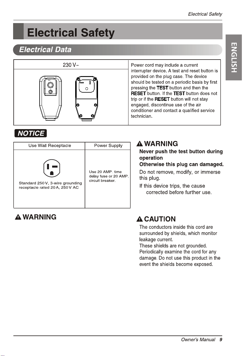
RESET
TEST
USE OF EXTENSION CORDS
RISK OF FIRE could cause serious injury or death
DO NOT use an extension cord with this window
air conditioner
DO NOT use surge protectors or multi-outlet
adapters with this window air conditioner
should
be
Avoid shock hazard. This unit cannot
be user-serviced. Do NOT open the
tamper-resistant sealed portion.
All warranties and performance will
be voided. This unit is not intended
to be used as an ON/OFF switch.
Page 10
WARNING:
This product contains chemicals known to
the State of California to cause cancer and birth defects
or other reproductive harm.
Wash hands after handling.
Page 11
Installation
Installation
Remove packing materials from the wall sleeve and tape
from the air conditioner.
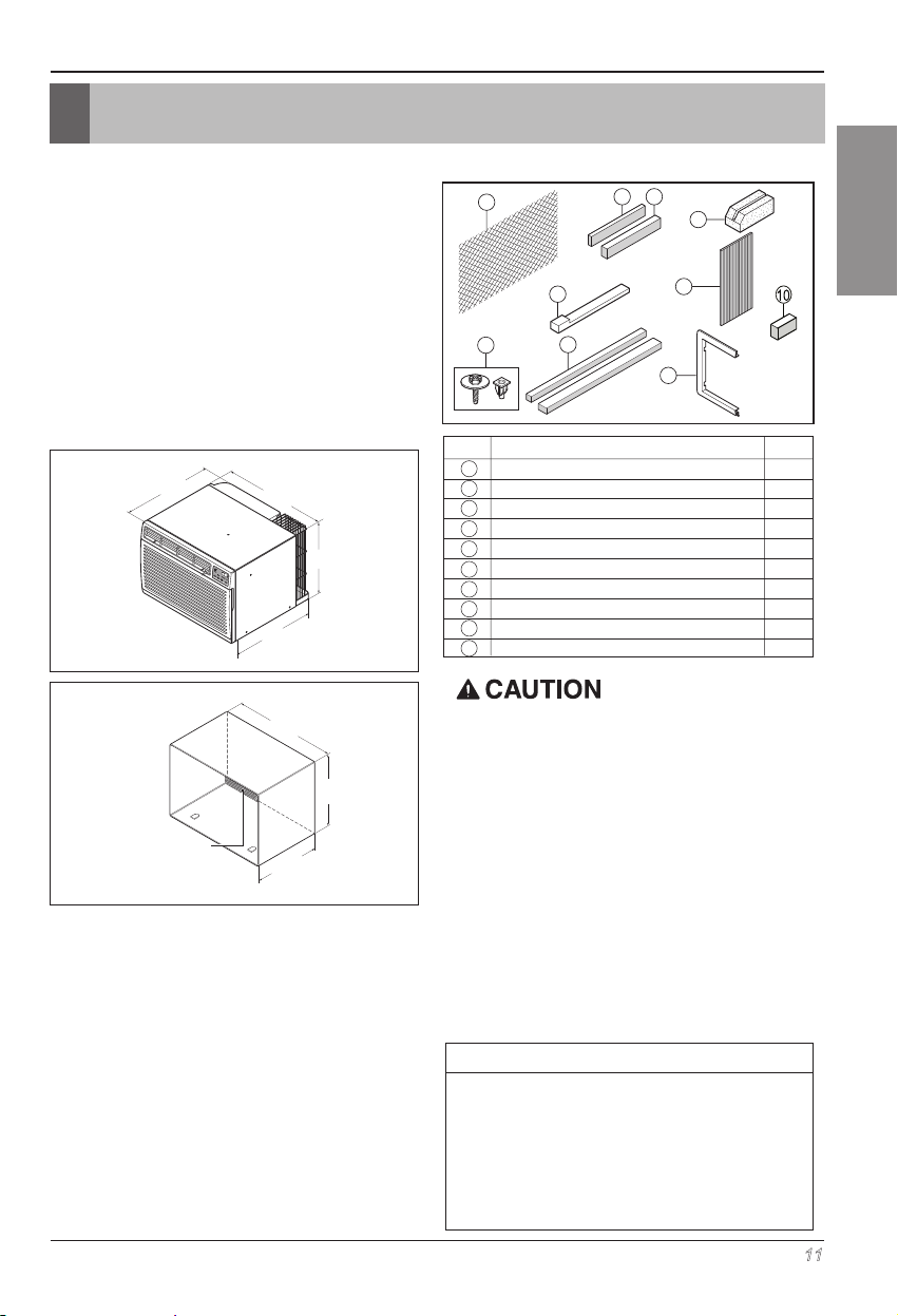
INSTALLATION REQUIREMENTS
If you use an existing wall sleeve, you should
measure its dimensions.
Install the new air conditioner according to these
installation instructions to achieve the best
performance. All wall sleeves used to mount the new
air conditioner must be in good structural condition
and havearear grille to securely attach the new air
conditioner. (Figure 1)
With the LGE sleeve(optionally supplied with
your unit), you can maintain the best performance of
the new air conditioner. (Figure 2)
20-3/32"
(511 mm)
Air Conditioner
Aluminum metal grille
LGE Wall Sleeve
ELECTRICAL SERVICE
Check your available electrical service. The power
supply available must be the same as that shown on
the unit nameplate (found on left side of cabinet).
All models are equipped with a 3-prong service plug
to provide proper service and safe positive
grounding. Do not change plug in any way. Do not
use an adapter plug. If your present wall outlet does
not match your plug, cal
make the necessary corrections. SAVE CARTON for
storage and this OWNER'S MANUAL for future
reference. The carton is the best way to store unit
during winter or when not in use.
24"(610 mm)
14-13/32"
(366 mm)
18-15/32"(468 mm)
Figure 1
25-7/8"
(656 mm)
15-17/32"
(394 mm)
16-23/32"
(425 mm)
l a qualified electrician to
Figure 2
INSTALLATION HARDWARE
1
8
9
ITEM NAME OF PARTS Q'TY
1 PLASTIC GRILLE 1
2 VERTICAL INSULATION STRIP 1
3 AROUND INSULATION STRIPS 2
4 HORIZONTAL INSULATION STRIP 1
5 SUPPORT BLOCK 2
6 BAFFLE 1
7 TRIM FRAME 2
8 SHIM 2
910PLASTIC NUTS AND WASHER SCREWS
INSULATION STRIP
2 4
2 Size options
3
2 Size options
5
6
7
4
1
To avoid risk of personal injury, property
damage, or product damage due to the weight of
this device and sharp edges that may be
exposed:
• Air conditioners covered in this manual pose an
excessive weight hazard. Two or more people are
needed to move and install the unit.
To prevent injury or strain, use proper lifting and
carrying techniques when moving unit.
• Carefully inspect location where air conditioner will
be installed. Be sure it will support the weight of
the unit over an extended period of time.
• Handle air conditioner with care. Wear protective
gloves whenever lifting or carrying the unit. AVOID
the sharp metal fins of front and rear coils.
• Make sure air conditioner does not fall during
installation.
REQUIRED TOOLS:
• Tight Fitting gloves
• Standard screwdriver
• Phillips screwdriver
• Pliers
• Sharp knife
• 3/8-inch open end
wrench or adjustable
wrench
• 1/4-inch hex socket
and ratchet
• Tape measure
• Electric drill
• 1/4-inch drill bit
ENGLISH
Owner’s Manual 11
Page 12
Installation
INSTALLATION
We strongly recommend the removal of the
old wall sleeve and the installation of a new
LGE Wall Sleeve.
If you decide to keep the existing wall sleeve,
you have to redirect the louvers at the back of
the wall sleeve illustration. The use of pliers is
recommended. If you DO NOT redirect, you
run the risk of poor performance or product
failure. This is not covered under the terms of
the LGE warranty.
• Pick a location which will allow the conditioned air
to blow into the area you want. Good installation
with special attention to the proper position of the
unit will lessen the chance that service will be
needed.
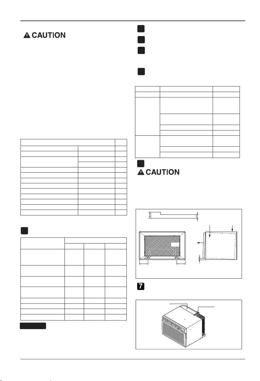
ITEMS IN INSTALLATION HARDWARE
You may not need all parts in the kit. Discard unused
parts.
Plastic grille 26
ITEM (inches) Qty.
Vertical insulation strip 15
Around Insulation Strips
Horizontal Insulation Strip 26
Support Block 1
Baffle
Shim 11
Trim Frame 2
Washer Screw 4
Nuts (Plastic) 4
Grille Rear 1
Insulation strip
67
59
3
14 x
5
5
3
1
/
/
x 16
4
2
9
3
/
/
x 1
16
8
1
3
/
/
x 1
8
8
27
3
/
/
x 1
32
3
3
/
/4
x 1
8
3
/
/
x 1
x 4
4
8
1
/
4
x
2
13
/
x 1 x
16
3
/
/
x 1
16
16
x 1
x
8
x 1
1
x
/
3
25
x 1
5
8
/
3
1
3
/
1
8
/
1
32
3
/
1
8
3
/16
1
/
2
16
1
2
4
/
1
4
HOW TO INSTALL
Identify the existing wall sleeve before installing
1
the unit from the listed below.
Brand
White-Westinghouse
Frigidaire
Carrier (52F series)
General Electric
/Hotpoint
Whirlpool 25-7/8 16-1/2
Fedders/Emerson 27 16-3/4
LGE 25-7/8 15-17/32 16-23/32
Emerson/Fedders 26-3/4 15-3/4 15
Carrier (51S Series) 25-3/4 16-7/8 18-5/8
Friedrich 27 16-3/4 16-3/4
NOTICE
All wall sleeves used to mount the new Air
Conditioner must be in sound structural condition
and have a rear grille that securely attaches to
sleeve, or rear flange that serves as a stop for the
Air Conditioner.
12 Room Air Conditioner
Wall Sleeve Dimensions (inches)
Width Height Depth
25-1/2 15-1/4
16, 17-1/2
or 22
26 15-5/8 16-7/8
17-1/8
or 23
16-3/4
or 19-3/4
Remove the old airconditioner from existing
2
wall sleeve.
Clean the interior of the existing sleeve.
3
(Do not disturb seals.)
Wall sleeve must be securely fastened in wall
4
before installing the air conditioner. Use the
nails or screws through sleeve into wall, if
needed. Repaint sleeve if needed.
Prepare the wall sleeve for installation of the
5
unit. If you plan to use your e
xisting wal
l sleeve,
and it is not LGE, use procedure B or C below.
Procedure Brand
Depth(inches)
A LGE 16-23/32
White-Westinghouse
Frigidaire Carrier
(52F series)
General Electric
B
/Hotpoint
16, 17-1/2
or 22
16-7/8
Whirlpool 17-1/8 or 23
Carrier (51S series)
Fedders/Emerson
C
Emerson/Fedders 15
18-5/8
16-3/4
or 19-3/4
Friedrich 16-3/4
Install new unit into wall sleeve.
6
When installation is completed, the replacement
unit MUST have a rearward slope as shown. To
achieve 1/4" slope, remove the backing from the
11-13/16" shim strips and attach them as shown
below in Fig. 3. Place the higher portion of the shim to
the front of the rib on the base of the wall sleeve.
1" high
Shim
6" 6"
SHIM PLACEMENT UNIT INSTALLATION
FRONT
1/4"
3
/4" High
UNIT
Wall Sleeve
Figure 3
Remove the backing from the insulation strip
5
/
16
5 x 1 x and attach that to the top of
3
3
/
/
4
16
the cover as show below.
Cover
Insulation
Page 13
Installation
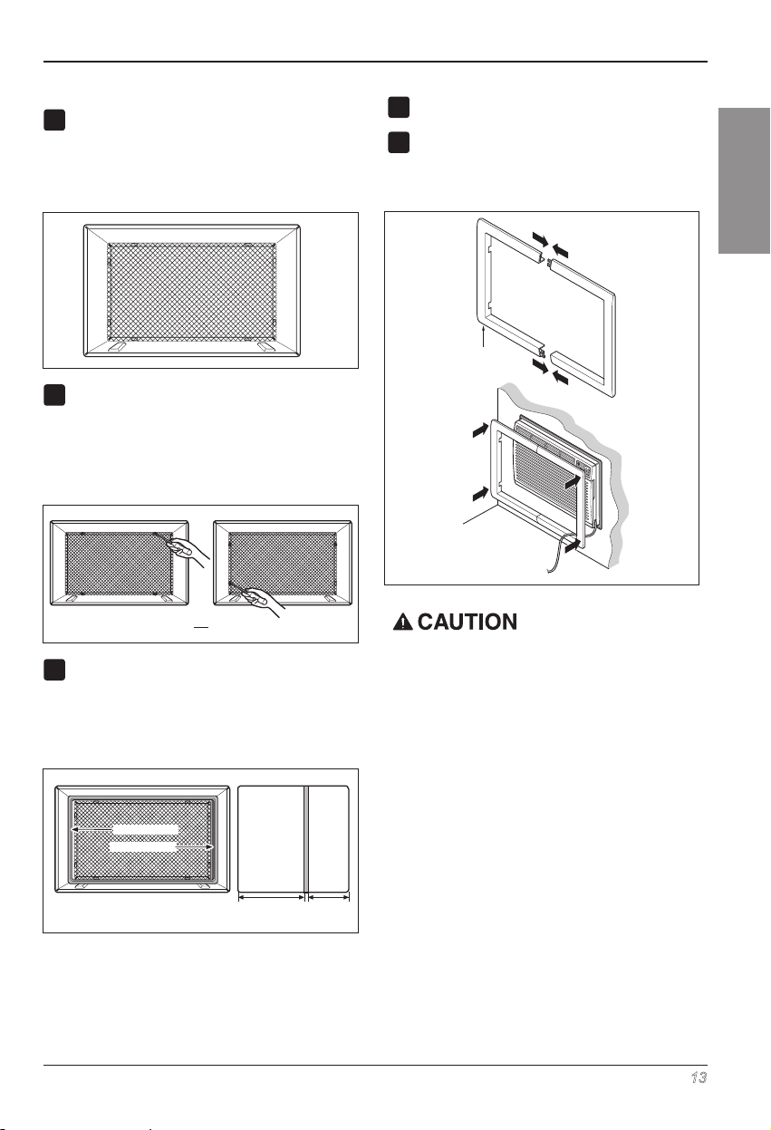
PROCEDURE A
If you are using the new sleeve (optionally
1
supplied with your unit), skip to step 3.
Otherwise, install the plastic grille from the kit.
Cut the plastic grille to 25-1/2" wide and 151/4" high. Place the plastic grille to the inside
of the wall sleeve at the rear flange.
Fasten the 4 washer screws to secure the grille
2
to the wall sleeve. If you need plastic nuts to
mount plastic grille to the inside of the wall
sleeve, there are plastic nuts in the installation
kit. The nuts are installed from the inside of the
sleeve and are pressed into the square holes
of the rear flanges.
Figure 4
Install the new unit into the wall sleeve.
4
To assemble trim,
5
into the slot of the other piece as shown below.
snap the tab of each piece
Slide trim over the front of the air conditioner
until trim is flush with sleeve as shown below.
Trim (2 ea)
Wall
ENGLISH
ENGLISH
7 erugiF
or
Remove the backing from the vertical insulation
3
strip 15
9
3
x 1
3
/
/
x 1
and attach that to the
8
8
/
16
inside right of the sleeve as shown below.
Remove the backing from the around insulation
1
3
strip 67
/
8
x 1
25
/
/
x
and attach that to the
8
32
inside front of the sleeve as shown below.
Indoor Outdoor
Around Insulation
Vertical Insulation
9 1/2" 6"
Figure 5
Figure 6
• Air conditioners covered in this manual pose an
excessive weight hazard. Two or more people are
needed to move and install the unit.
To prevent injury or strain, use proper lifting and
carrying techniques when moving unit.
• When handling the air conditioner, be careful to
avoid cuts from sharp metal fins on front and rear
coils.
• Make sure air conditioner does not fall during
removal.
• If unit does not operate after installation check, to
be sure the circuit interrupter has not been tripped.
Refer to the Troubleshooting guide for reset
procedure.
Owner’s Manual 13
Page 14
Installation
PROCEDURE B
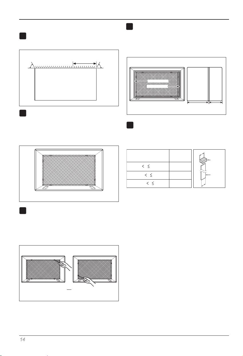
Redirect the louvers at the back of the wall
1
The use of pliers is recommended.
3
7
/
"
60°
Rear Louvers
(Top View)
If the wall sleeve already has a rear grille, skip
2
to step 4. If the wall sleeve does not have a rear
grille or louvered panel, install the plastic grille
from the kit. Cut the plastic grille to 25-1/2" wide
and 15-1/4" high. Place the plastic grille to the
inside of the wall sleeve at the rear flange.
32
.8 erugiF ni nwohs sa elgna °06 ot eveels
60°
Figure 8
Remove the backing from the Vertical Insulation
4
strip 15
9
3
x 1
3
/
/
x 1
and attach that to the
8
8
/
16
inside right of the sleeve as shown below.
ve the backing from the Around Insulation
Remo
1
3
strip 67
/
8
x 1
25
/
/
x
and attach that to the
8
32
inside front of the sleeve as shown below.
Indoor Outdoor
Around Insulation
Vertical Insulation
9 1/2" 6"
If the depth of your existing wall sleeve is less
5
than or equal to 18", skip to step 6. Otherwise,
cut the baffles and the support blocks according
to length A in the table below.
Depth D of the existing
wall sleeve (inches)
8
D 19-3/
8
4
18 D 18-5/
18-5/
19-3/4 D 22
Length A
(inches)
3
/4
1-3/4
4
A
A
Figure 11
Support
Block
Baffle
Figure 12
Place the plastic grille
Fasten the 4 washer screws to secure the grille
3
to the wall sleeve. If you need plastic nuts to
mount plastic grille to the inside of the wall
sleeve, there are plastic nuts in the installation
kit. The nuts are installed from the inside of the
sleeve and are pressed into the square holes of
the rear flanges.
or
Fasten the screws
14 Room Air Conditioner
Figure 9
Figure 10
Page 15
Owner’s Manual 15
PROCEDURE B
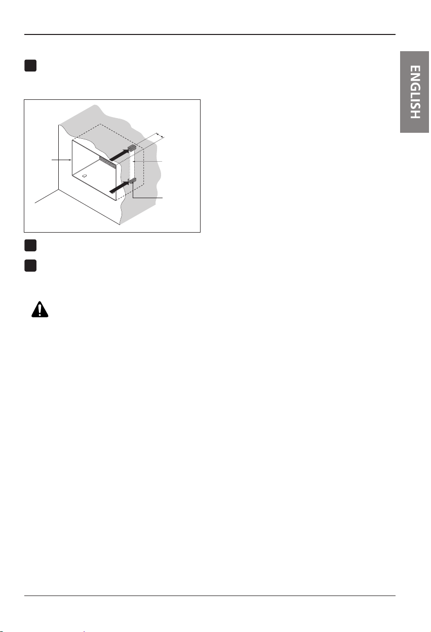
8
Remove the backing from the support blocks
6
and attach them to the inside of the wall sleeve
as shown Figure 13 . Slide the baffle into
slots of the support blocks.
Wall
in
(
Installation
3
7
"
)
/
32
Wall
Sleeve
Front
Install the new unit into the wall sleeve.
7
Assemble trim as described in Step 5,
Procedure A.
Baffle
Support
Block
Figure 13
CAUTION
• Air conditioners covered in this manual pose an
excessive weight hazard. Two or more people are
needed to move and install the unit.
To prevent injury or strain, use proper lifting and
carrying techniques when moving unit.
• When handling the air conditioner, be careful to
avoid cuts from sharp metal fins on front and rear
coils.
• Make sure air conditioner does not fall during
removal.
• If unit does not operate after installation check, to be
sure the circuit interrupter has not been tripped.
Refer to the Troubleshooting guide for reset
procedure.
Page 16
Installation
PROCEDURE C
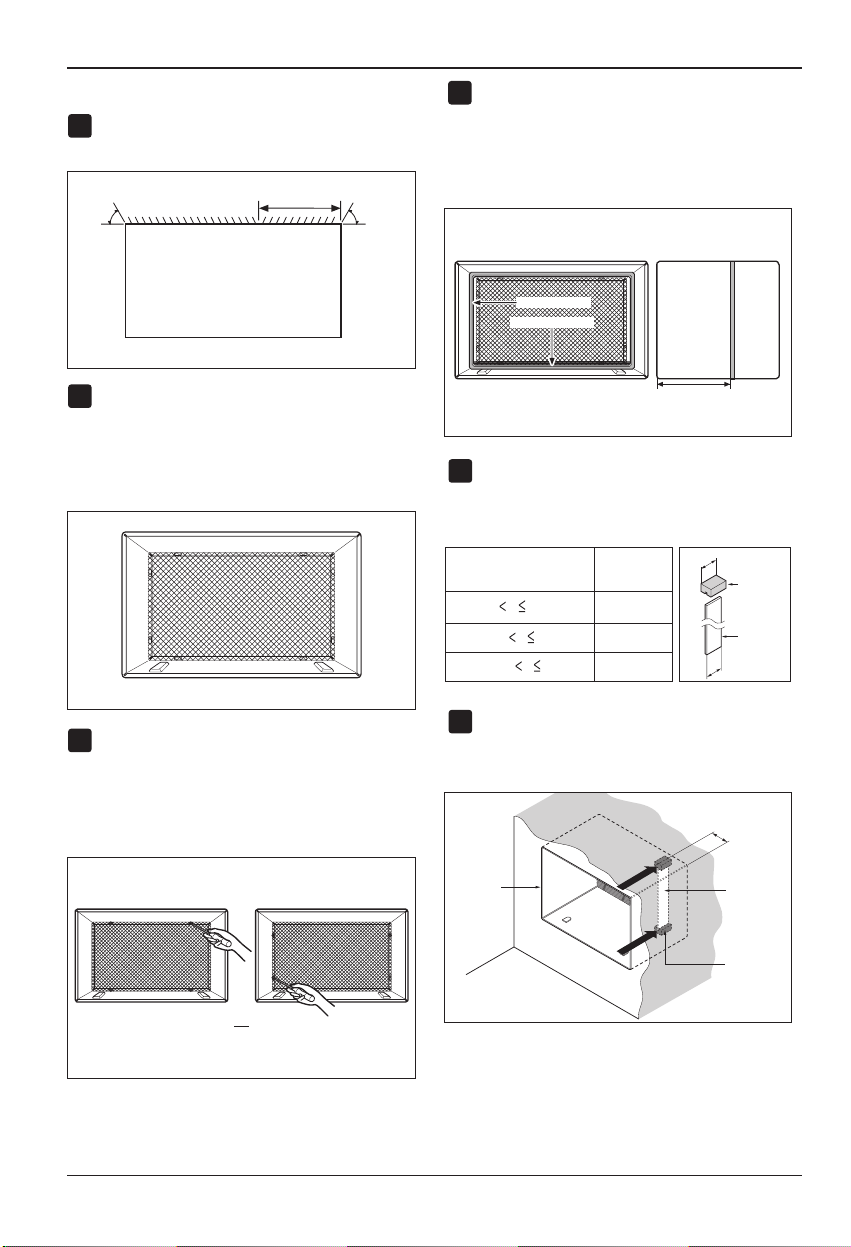
Redirect the louvers at the back of the wall
1
The use of pliers is recommended.
3
7
"
/
60°
Rear Louvers
(Top View)
If the wall sleeve already has a rear grille, skip
2
to step 4. If the wall sleeve does not have a rear
grille or louvered panel, install the plastic grille
from the kit. Cut the plastic grille to 26-1/2" wide
and 15-1/2" high. Place the plastic grille to the
inside of the wall sleeve at the rear flange.
Place the plastic grille
Fasten the 4 washer screws to secure the grille
3
to the wall sleeve. If you need plastic nuts to
mount plastic grille to the inside of the wall
sleeve, there are plastic nuts in the installation
kit. The nuts are installed from the inside of the
sleeve and are pressed into the square holes of
the rear flanges.
32
.41 erugiF ni nwohs sa elgna °06 ot eveels
60°
Figue 14
Figure 15
Remove the backing from the horizontal
4
insulation strip 26
that to the insid
below. Remove the backing from the around
insulation strip 59
3
3
x 1
3
/
/
x 1
and attach
8
16
/
4
e right of the sleeve as shown
27
3
x 1
/
8
x 1
3
/
and attach
8
/
32
that to the inside front of the sleeve as shown
below.
Indoor Outdoor
Around Insulation
Horizontal Insulation
8 1/2"
71 erugiF
If the depth of your existing sleeve is less than
5
or equal to 18”, skip to step 7. Otherwise, cut
the baffles and the support blocks according to
Length A in the table below.
Depth D of the existing
wall sleeve (inches)
18 D 18-5/
18-5/
19-3/4 D 22
8
D 19-3/
8
4
Length A
(inches)
3
/4
1-3/4
4
A
A
Support
Block
Baffle
Figure 18
Remove the backing from the support blocks
6
and attach them to the inside of the wall sleeve
as shown in Figure 19.
Slide the baffle into slots
of the support blocks
3
/
(7
")
Wall
32
or
Fasten the screws
16 Room Air Conditioner
Figure 16
Wall
Sleeve
Front
Baffle
Support
Block
Figure 19
Page 17
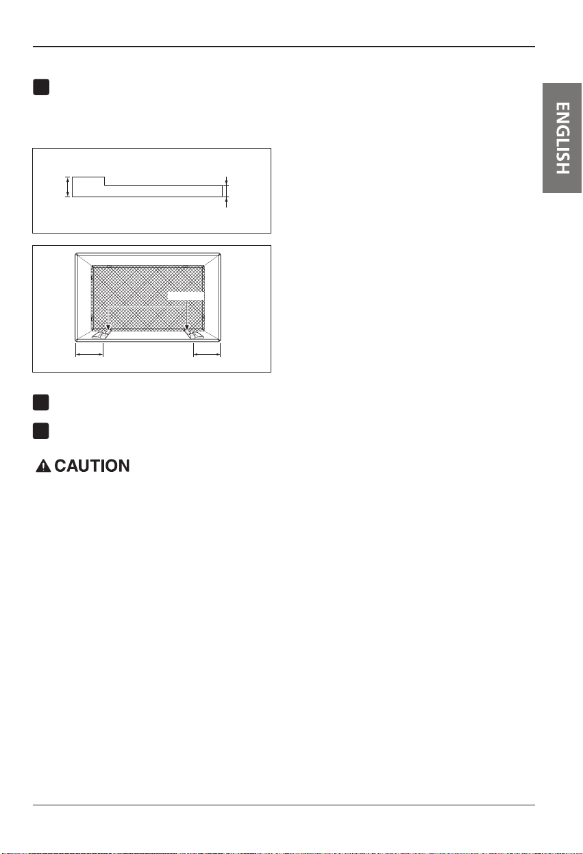
To achieve rearward slope for unit draining,
7
remove the backing from the 11
strips and attach them as shown below in Figure
21. The higher portion of shim is to be placed
in front of the rib on the base of wall sleeve.
13
/
" shim
16
Installation
1" high
Shim (2EA)
6" 6"
Install the new unit into the wall sleeve.
8
Assemble trim as described in Step 6,
9
Procedure A.
3
/4" High
Figure 20
Figure 21
• Air conditioners covered in this manual pose an
excessive weight hazard. Two or more people are
needed to move and install the unit.
To prevent injury or strain, use proper lifting and
carrying techniques when moving unit.
• When handling the air conditioner, be careful to avoid
cuts from sharp metal fins on front and rear coils.
• Make sure air conditioner does not fall during
removal.
• If unit does not operate after installation check, to be
sure the circuit interrupter has not been tripped.
Refer to the Troubleshooting guide for reset
procedure.
Owner’s Manual 17
Page 18
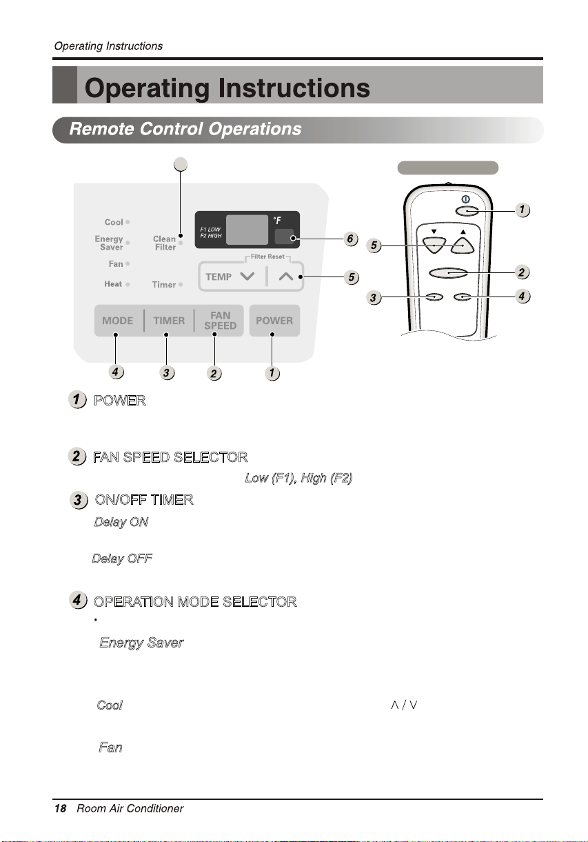
7
REMOTE CONTROLLER
Fan Speed
Timer Mode
POWER
Operation starts when this button is pressed and stops when you
press the button again.
FAN SPEED SELECTOR
Use to set the fan speed to
Low (F1), High (F2)
.
ON/OFF TIMER
Delay ON
on from 1 to 24 hours at its previous mode and fan settings.
Delay OFF
off from 1 to 24 hours.
- when the air conditioner is off, it can be set to automatically turn
- when the air conditioner is on, it can be set to automatically turn
Temp
OPERATION MODE SELECTOR
Push the MODE button to rotate between Energy Saver / Cool / Fan / Heat.
Energy Saver - The fan stops when the compressor stops cooling.
Approximately every 3 minutes the fan will turn on and check the room air
temperature if cooling is needed.
- Compressor runs and cools the room. Use the
Cool
and FAN buttons
to set the desired temperature and circulation fan speed.
Fan - Fan circulates air but compressor does not run. Use the FAN button to set
the desired fan speed.
Page 19
Fan runs continually for normal heating operation.
-
Heat
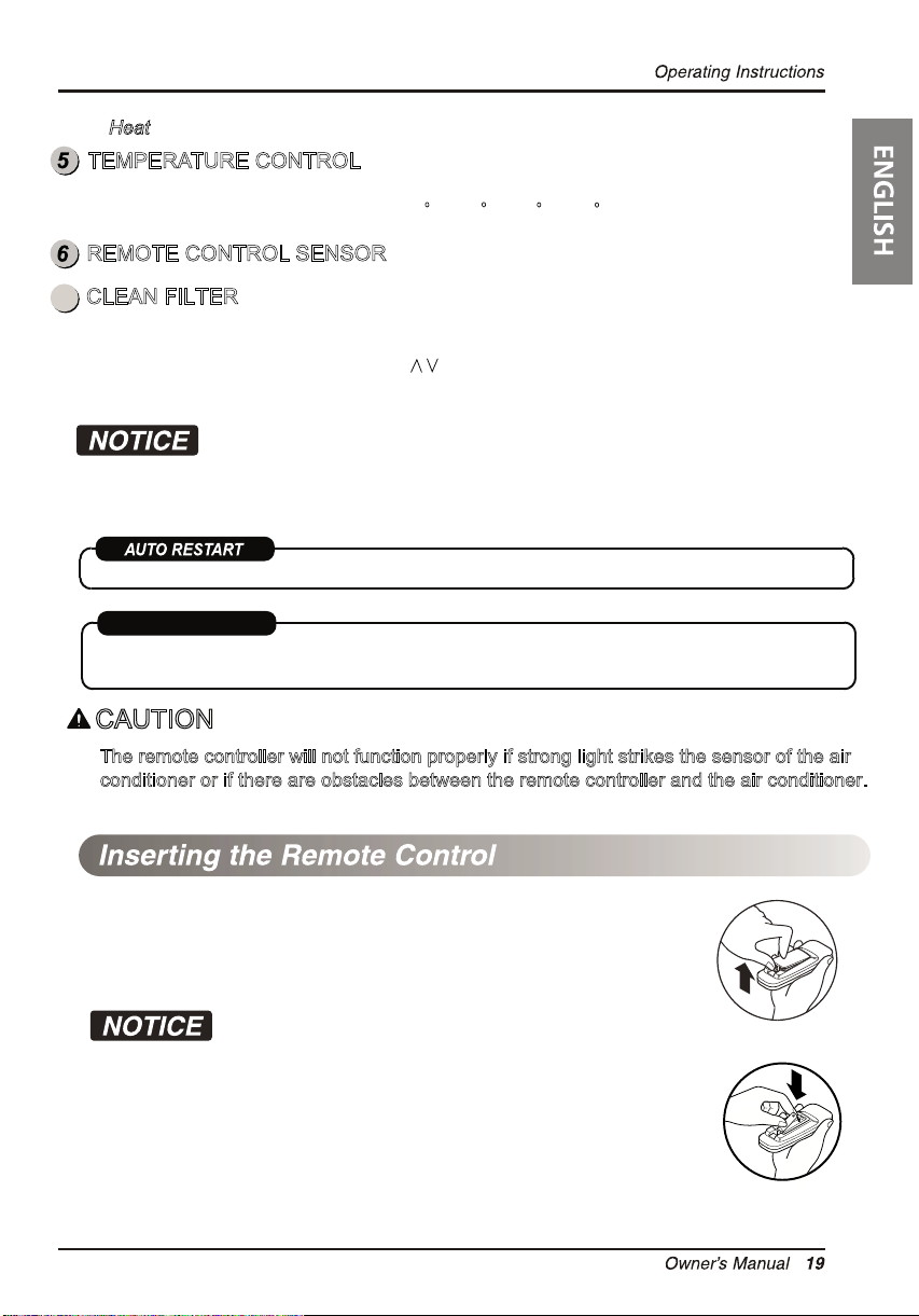
TEMPERATURE CONTROL
The thermostat monitors room temperature to maintain the desired temperature.
The thermostat can be set between 60
F~86 F (16 C~30 C).
REMOTE CONTROL SENSOR
CLEAN FILTER
7
‘Clean Filter’ LED will light up to notify you that your filter needs to be cleaned.
After cleaning the filter, press “Temp ”
together to turn off ‘Clean Filter’ light.
(Filter reset must be done from unit control panel not remote control).
This feature is reminder to clean the Air Filter (See Maintenance) for more efficient operation.
The LED (light) will illuminate after 250 hours of operation.
During operation in failure of electric power, the unit runs as previous setting operation.
ENERGY SAVER
ENERGY SAVER
The unit defaults to Energy Saver mode each time the unit is switched on except
restoration after an electrical power outage and fan mode.
CAUTION
The remote controller will not function properly if strong light strikes the sensor of the air
conditioner or if there are obstacles between the remote controller and the air conditioner.
Battery
1. Push out the cover on the back of the remote control with your thumb.
2. Pay attention to polarity and insert one new AAA 1.5 V battery.
3. Reattach the cover.
Do not ure rechargeable battery. Make sure that the battery is new.
Do not mix alkaline, standard (Carbon-zinc) or rechargeable (Nickel-cadmium)
battery.
- In order to prevent discharge, remove the batteries from the remote control if
the air conditioner is not going to be used for an extended period of time.
Keep the remote control away from extremely hot or humid places.
To maintain optimal operation of the remote control, the remote sensor should
not be exposed to direct sunlight.
Page 20
20 Room Air Conditioner
Operating Instructions
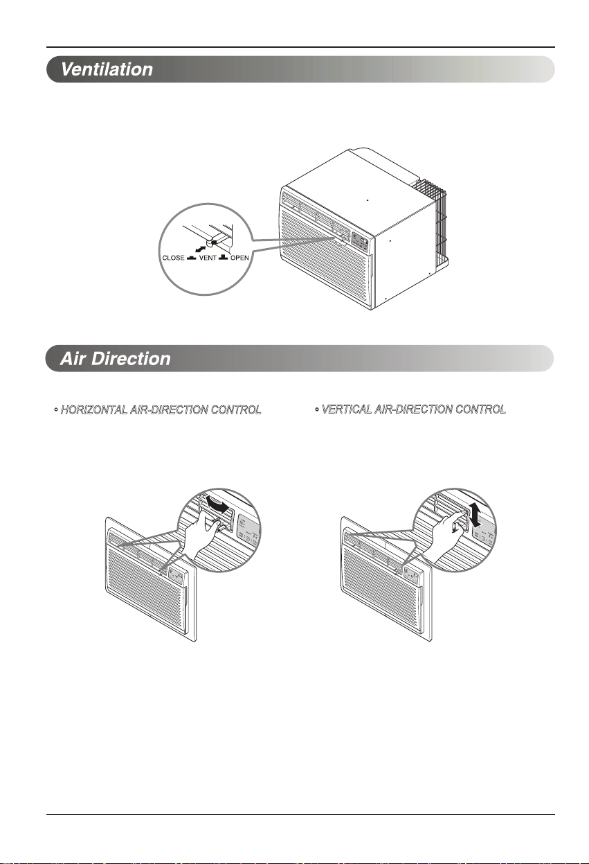
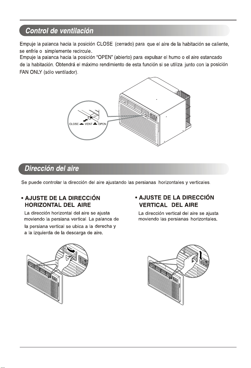
The ventilation lever is located in the right of the air discharge.The ventilation lever must be in the CLOSE
posotion in order to maintain the best cooling conditions. When fresh air is necessary in the room, set
the ventilation lever to the OPEN position. The damper is opened and room air is exhausted outside.
The direction of air can be controlled wherever you want by adjusting the horizontal louver and the vertical louver.
• HORIZONTAL AIR-DIRECTION CONTROL
• VERTICAL AIR-DIRECTION CONTROL
The horizontal air direction is adjusted by moving
vertical louver.
The lever of vertical louver is located in the right and
left side of the air discharge.
The vertical air direction is adjusted by moving
the horizontal louver.
Page 21
Maintenance and Service
MODE TIMER POWER
FAN
SPEED
Fan
Energy
Saver
Cool
Timer
TEMP
'
F
F1 LOW
F2 MED
F3 HIGH
Maintenance and Service
TURN THE AIR CONDITIONER OFF AND REMOVE THE PLUG FROM THE POWER OUTLET.
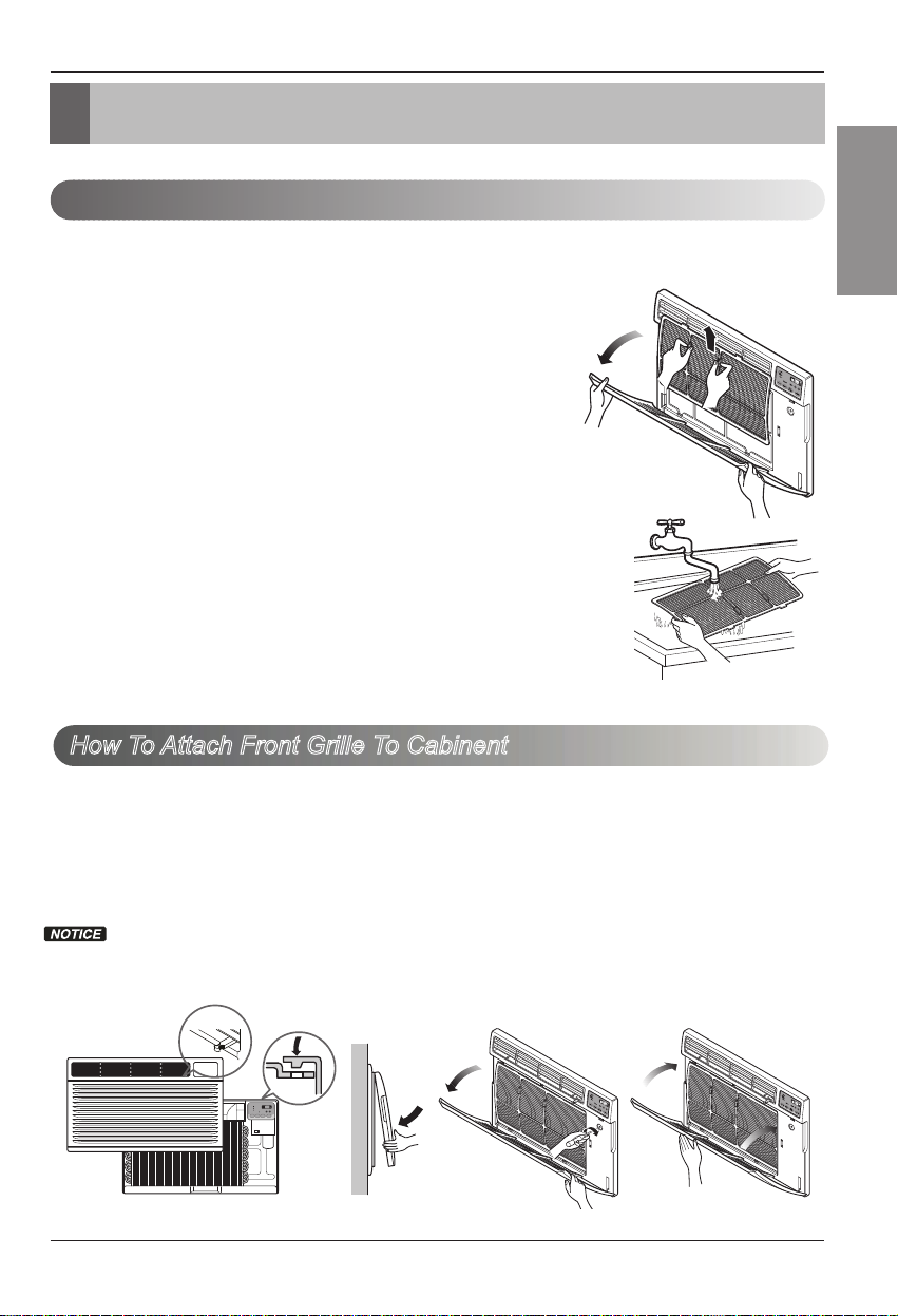
Air Filter Cleaning
The air filter should be checked at least twice a month to see if cleaning is necessary.
Trapped particles in the filter will build up and block the airflow. This reduces the cooling
capacity and also causes an accumulation of frost on the cooling coils.
If the filter becomes turn or damaged you should replace
immediately. Replacement filters are available from your
salesperson, dealer, and the authorized customer service
centers.
1. Open the inlet grille downward by pulling out the top of the
inlet grille.
2. Remove the air filter from the front grille assembly by
pulling the air filter up slightly.
3. Wash the filter using lukewarm water below 40 °C (104 °F).
4. Gently shake the excess water from the filter completely.
Replace the filter.
ENGLISH
How To Attach Front Grille To Cabinent
The front grille can be removed for cleaning or to check the model and serial numbers.
For your safety, you should attach the front grille as the following procedures.
1. Pull down fro
2. Push front grille’s tips toward the cabinet in
order to insert front grille’s tabs into the
cabinet.
Guide the lever carefully through the
grille as you push it in.
nt grille from the cabinet top.
3. Open the inlet grille.
4. Tighten the screw through the front grille into
the plate of control box.
5. Close inlet grille.
Owner’s Manual 21
Page 22
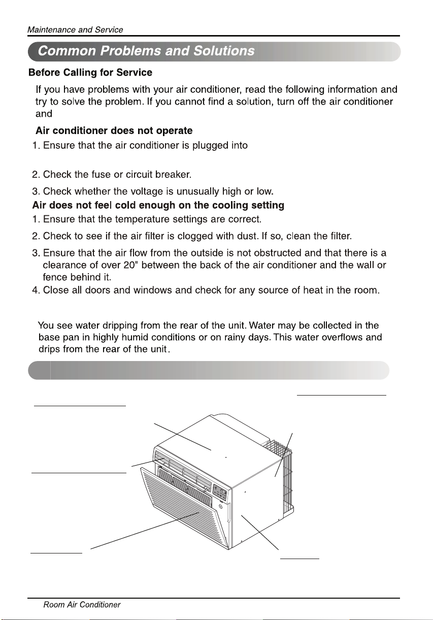
call 1-800-243-0000.
voltage and amperage.
Water drip from the rear of the unit
Normal Sound
an outlet of the proper
High pitched Chatter
Today’s high efficiency compressors
may have a high pitched chatter
during the cooling cycle.
Sound of Rushing Air
At the front of the unit, you
may hear the sound of rushing
air being moved by the fan.
Gurgle/Hiss
“Gurgling or hissing” noise may be
heard due to refrigerant passing
through evaporator during normal
operation.
22
Pinging or Swishing
Droplets of water hitting
condenser during normal
operation may cause
“pinging or swishing” sounds.
Vibration
Unit may vibrate and
make noise because of poor
wall or window construction
or incorrect installation.
Page 23
ENGLISH
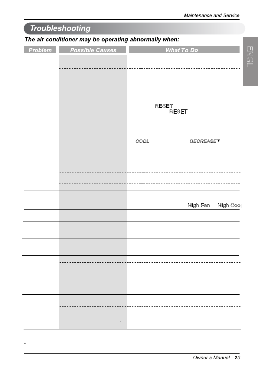
Air
conditioner
does not
start
Air conditioner
does not cool
as it should
Air conditioner
freezing up
Water drips
outside
Water drips
indoors
Water collects
in base pan
Air conditioner
turns on and
off rapidly.
Noise when
unit is cooling.
Remote
Sensing
Deactivating
Prematurely.
Room too
cold.
The air conditioner is
unplugged.
The fuse is blown/circuit
breaker is tripped.
Power failure.
The current interrupter
device is tripped.
Airflow is restricted.
The temp control may not
be set correctly.
The air filter is dirty.
The room may have been
hot.
Cold air is escaping.
Cooling coil have iced up.
The cooling coils are iced
over.
Hot, humid weather.
The air conditioner is not
tilted to the outside.
Moisture removed from air
and drains into base pan.
Dirty air filter - air
Outside temperature
extremely hot.
Air movement sound.
Window vibration - poor
installation.
Remote control not located
within range.
Remote control signal
obstructed.
Set temperature too low
restricted.
Make sure the air conditioner plug is pushed
completely into the outlet.
Check the house fuse/circuit breaker box and
replace the fuse or reset the breaker.
If power failure occurs, turn the mode control
to Off. When power is restored, wait 3 minutes
to restart the air conditioner to prevent tripping
of the compressor overload.
Press the RESET
cord plug. If the RESET
engaged, discontinue use of the air conditioner
and contact a qualified service technician.
Make sure there are no curtains, blinds, or
furniture blocking the front of the air conditioner.
In COOL model,press the DECREASE pad.
Clean the filter at least every 2 weeks.
See the care and Maintenance section.
When the air conditioner is first turned on, you
need to allow time for the room to cool down.
Check for open furnace floor registers and cold
air returns.
See Air Conditioner Freezing Up below.
Ice may block the air flow and obstruct the air
conditioner from properly cooling the room.
Set the mode control at High Fan
This is normal.
For proper water disposal, make sure the air
conditioner slants slightly from the case front
to the rear.
This is normal for a short period in areas with
little humidity; normal for a longer period in
very humid areas.
Clean air filter.
Set FAN speed to a faster setting to bring air
through cooling coils more frequently.
This is normal. If too loud, set to lower FAN setting.
Refer to installation instructions or check with
installer.
Place remote control within 20 feet & 120° radius
of the front of the unit.
Remove obstruction.
lncrease set temperature.
button located on the power
button will not stay
or High Cool
.
If you see “CH” in the display, please call 1-800-243-0000.
3
Page 24
24 Aire Acondicionador
Manual del usuario del acondicionador de aire tipo Ventana
TABLA DE CONTENIDOS
PARA SUS ARCHIVOS
Escriba aquí el modelo y número de serie:
Modelo n°:
Serie n°:
Puede encontrar estos datos en la etiqueta situada en el
lateral de cada unidad.
Nombre del distribuidor:
Fecha de compra:
■ Adjunte su recibo a esta página con la grapadora para
el momento que lo necesite para probar la fecha de su
adquisición o para la validación de la garantía.
LEAESTEMANUAL
En su interior encontrará muchos consejos útiles sobre la
utilización y mantenimiento de su acondicionador de aire.
Unos pocos cuidados por su parte le pueden ahorrar
mucho tiempo y dinero durante la vida de su
acondicionador de aire.
Enlatabladeconsejosparalasoluciónrápidade
problemas encontrará muchas respuestas a los problemas
más habituales. Si revisa primero nuestra Tabla d e
Consejos para la solución rápida de problemas, tal vez no
necesite llamar nunca al servicio técnico.
PRECAUCIÓN
• Póngase en contacto con un técnico del servicio
autorizado para realizar la reparación y
mantenimiento de esta unidad.
• Póngase en contacto con un instalador para realizar
lainstalacióndeestaunidad.
• Cuando se va a cambiar el cable eléctrico, el trabajo
de reemplazamiento debe ser realizado únicamente
por personal autorizado, utilizando las piezas de
cambio genuinas únicamente.
• El trabajo de reemplazamiento debe ser realizado de
acuerdo con el Código Eléctrico Nacional
únicamente por personal autorizado.
Precauciones de Seguridad .........25
Antesdeponerelequipoen
funcionamiento..............................29
Introducción...................................30
Seguraida Electrica.......................31
Instalacion......................................33
Instruccionnes de
Funcionamiento.............................40
Cuidado y Mantenimiento ............43
Page 25
Manual del Propietario 25
ESPAÑOL
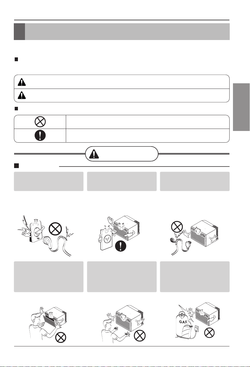
Precauciones de Seguridad
ADVERTENCIA
Gasolin
ADVERTENCIA
PRECAUCION
Este símbolo indica la posibilidad de muerte o de seria lesión.
Este símbolo indica sólo la posibilidad de lesiones o daños a la propiedad
Precauciones de Seguridad
Para evitar lesiones al usuario o a otras personas y daños a la propiedad, estas instrucciones
estén seguirse.
Una operación incorrecta por ignorar las instrucciones provocará lesiones o daños. La seriedad se clasifica
por las siguientes indicaciones.
Significados de los símbolos utilizados en este manual.
No hacer.
Siga estas instrucciones.
Instalación
No utilice un cable de
alimentación, enchufe o una
toma suelta que esté dañada.
• De lo contrario, podría provocar
un incendio o descarga
eléctrica.
Enchufe siempre a un
tomacorriente que tenga
toma a tierra.
• De lo contrario, podría provocar
un incendio o descarga
eléctrica.
No modifique ni alargue el
cable de alimentación.
• De lo contrario, puede provocar
una descarga eléctrica o
incendio debido a la
generación de calor.
No desmonte ni modifique
los productos.
• Puede ocasionar fallos y una
descarga eléctrica.
Tenga cuidado al
desembalar e instalar el
aparato.
• Los bordes afilados pueden
provocar lesiones.
No use el cable de alimentación
cerca gas inflamable o
materiales combustibles tales
como la gasolina, benceno,
disolvente, etc.
• Podría ocurrir una explosión o
incendio.
Page 26
26 Aire Acondicionador
Precauciones de Seguridad
Wax
Thinner
Operación
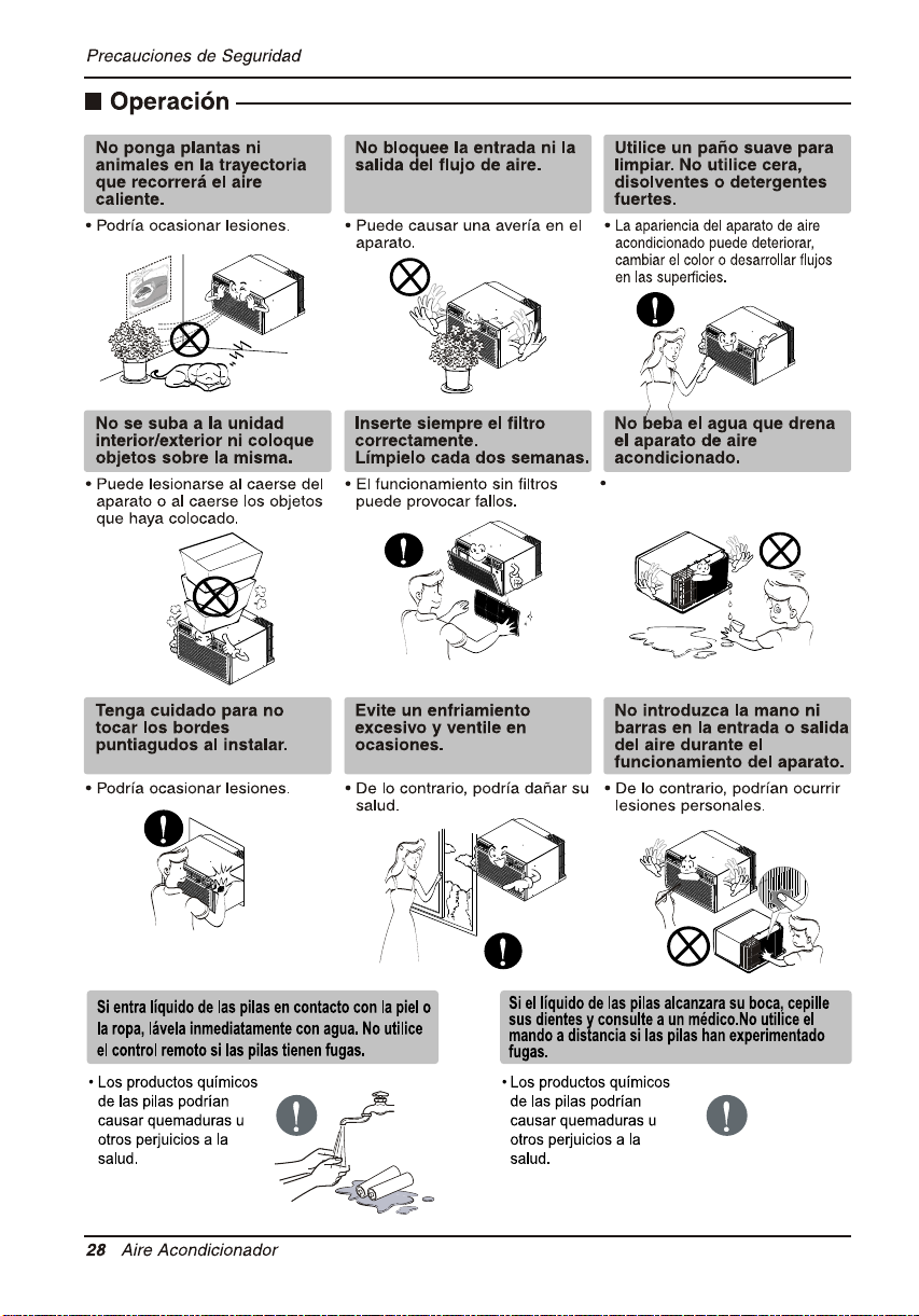
No use el cable de alimentación
cerca gas inflamable o materiales
combustibles tales como la
gasolina, benceno, disolvente, etc.
• Puede ocasionar una explosión
o descarga eléctrica.
No comparta el
tomacorriente con otros
electrodomésticos.
•
De lo contrario, puede provocar una
descarga eléctrica o incendio debido
a la generación de calor.
Saque el enchufe en caso de
necesidad, sosteniendo la
cabeza del enchufe y no lo
toque con las manos mojadas.
•
De lo contrario, podría provocar un
incendio o descarga eléctrica.
No ponga el cable de
alimentación cerca de un
calentador.
• Puede ocasionar un incendio y
una descarga eléctrica.
Desenchufe la unidad si oye
un sonido extraño, olores, o
si observa salir humo.
• De lo contrario, puede ocurrir
un incendio y un accidente por
descarga eléctrica.
Ventile bien la sala al usar
este aparato con una estufa,
etc.
• Puede ocurrir un falta de
oxígeno.
No permita que entre agua
en las piezas eléctricas.
• Puede provocar fallos en el
producto o descargas
eléctricas.
No abra la parrilla de
entrada al aparato mientras
está en funcionamiento.
• De lo contrario, pueden ocurrir
descargas eléctricas y fallos.
Apague el aparato y el
interruptor diferencial
primero antes de limpiar la
unidad.
•
Debido a que el ventilador gira a
alta velocidad durante el
funcionamiento, podría ocasionar
lesiones.
Utilice un paño suave para
limpiar. No utilice cera,
disolventes o detergentes
fuertes.
•
La apariencia del aparato de aire
acondicionado puede deteriorar,
cambiar el color o desarrollar flujos
en las
superficies.
Si entra agua en el producto,
apague el interruptor de la
carcasa principal del aparato.
Póngase en contacto con el
centro de servicio después de
haber sacado el enchufe del
tomacorriente.
Apague el interruptor de
alimentación principal cuando
no vaya a utilizar el aparato
durante mucho tiempo.
• Evitará el arranque accidental y
la posibilidad de lesiones.
Page 27
Manual del Propietario 27
ESPAÑOL
Precauciones de Seguridad
ADVERTENCIA
No opere ni detenga la
unidad insertando o
estirando de enchufe.
• De lo contrario, puede provocar
una descarga eléctrica o
incendio debido a la
generación de calor.
Sostenga el enchufe por su
cabeza al sacarlo.
No dañe ni use un enchufe
de alimentación no
especificado.
• Provocará descargas eléctricas
o incendios.
Cuando haya un escape de
gas, abra la ventana para
ventilar antes de poner en
No toque el producto con
las manos mojadas o en un
ambiente húmedo.
• Provocará descargas
eléctricas.
No toque las partes
metálicas del aparato al
sacar el filtro del aire.
marcha la unidad.
• Podría ocasionar una descarga
eléctrica y daños.
Para una limpieza interior, póngase en contacto con un Centro de Servicios Autorizado
o un revendedor.
No utilice detergentes abrasivos que causan corrosión o dañan la unidad.
Los detergentes abrasivos pueden igualmente provocar un fallo del producto,
un incendio o una descarga electrónica.
• De lo contrario, podría ocurrir
una explosión o incendio.
• Son puntiagudas y pueden
provocar lesiones.
Instalación
Instale el producto de modo que el ruido o
el aire caliente producido por la unidad
externa no moleste a los vecinos.
• De lo contrario puede dar lugar a disputas
vecinales.
Mantenga nivelado el producto al instalarlo.
• De lo contrario se podría causar vibraciones o
escapes de agua.
Page 28
Contiene elementos de contención
y hacer que se enferme
Page 29

Antes de poner el equipo en funcionamiento
Manual del Propietario 29
Para cuestiones de reparación y mantenimiento, póngase en contacto con su
distribuidor de servicio autorizado.
Preparación para el funcionamiento
Uso
Limpieza y mantenimiento
Servicio
ESPAÑOL
Antes de poner el equipo en funcionamiento
1. Póngase en contacto con un especialista para realizar la instalación.
2. Enchufe correctamente la toma de alimentación.
3. Utilice un circuito dedicado.
4. No utilice un cable alargador.
5. No inicie/cese el funcionamiento enchufando/desenchufando el cable
eléctrico.
6. Si el cable/enchufe está dañado, sustitúyalo solo por una pieza autorizada.
1. Estando expuesto a la circulación directa de aire durante un extenso período
de tiempo podría resultar peligroso para su salud.
2. Debido a la probabilidad de falta de oxígeno, ventile el cuarto cuando esté
utilizado el aparato junto con estufas u otros aparatos de calefacción.
3. No utilice este aire acondicionado con propósitos especiales no especificados
(Ej.: conservación de dispositivos de precisión, comida, animales domésticos,
plantas y objetos de arte). Tal uso podría dañar los artículos.
1. No toque las piezas metálicas de la unidad al retirar el filtro. Manejar aristas
afiladas de metal puede causar lesiones.
2. No utilice el agua para limpiar el interior del aire acondicionado. La exposición
al agua puede destruir el aislamiento, conduciendo a posibles descargas
eléctricas.
limpiar la unidad, asegúrese antes de que la electricidad y el interruptor
3. Al
están apagados. El ventilador rota a muy alta velocidad durante el
funcionamiento del equipo. Existe la posibilidad de lesiones si acciona
accidentalmente la electricidad de la unidad mientras limpia el interior de la
unidad.
Page 30
30 Aire Acondicionador
Introducción
Este símbolo lo advierte de un peligro de accidente por
corriente eléctrica.
Este símbolo lo adiverte de un peligro que pueda causar un
daño del ventliador.
Este símbolo significa condicciones especiales.
CONSEJO
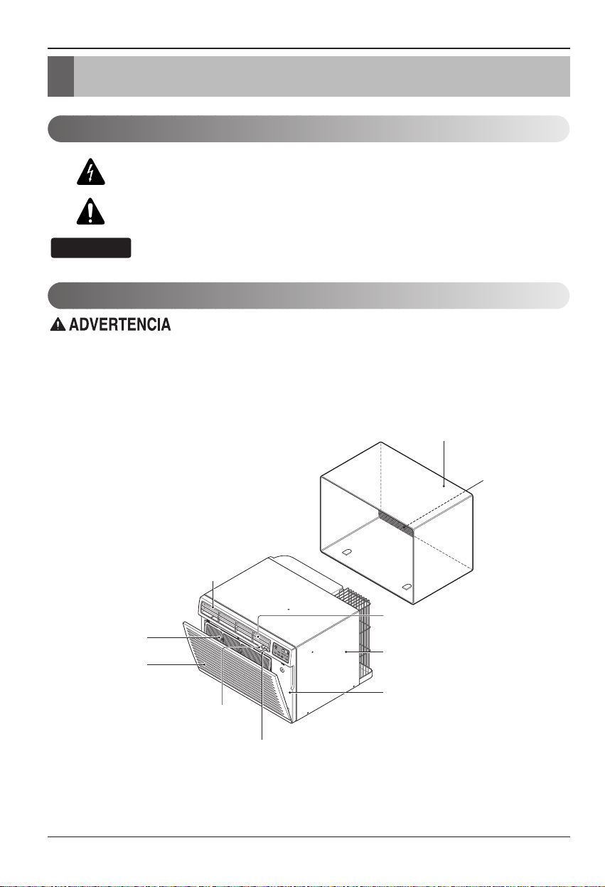
Introducción
Símbolos Utilizados en Este Manual
Características
Este aparato debería instalarse de acuerdo con las normas del Código Eléctrico Nacional.
EL SOPORTE DE PARED Y
LA REJILLA POSTERIOR
(incluido opcionalmente con su unidad)
MONTAJE DEL SOPORTE DE PARED
(Incluyendo rejilla posterior de aluminio)
REJILLA POSTERIOR
(Rejilla posterior
de aluminio)
FILTRO DE AIRE
REJILLA DE ENTRADA
DEFLECTOR VERTICAL DE AIRE
(Rejilla de ventilación horizontal)
(Toma de aire)
DEFLECTOR HORIZONTAL DE AIRE
(Rejilla de ventilación vertical)
CONTROL DEL ORIFICIO DE VENTILACIÓN
EL UNIDAD
DESCARGA
DE AIRE
ARMARIO
REJILLA
FRONTAL
Page 31
Seguraida Electrica
CONSEJO
Datos Electricos
Seguraida Electrica
230 V~
RESET
TEST
Utilice el enchufe de la pared Consumo de Energía
Utilice un fusible de
20 AMP. o un
Standard 250 V, enchufe de 3
Líneas de 20 A, 250 V AC
Interruptor de 20 AMP.
USO DE PROLONGADORES
RIESGO DE INCENDIO. Podría ocasionar
lesiones graves o la muerte.
NO use un prolongador con este
Acondicionador de Aire de Ventana.
NO use protectores contra picos de tensión ni
adaptadores para múltiples tomacorrientes con
este Acondicionador de Aire de Ventana.
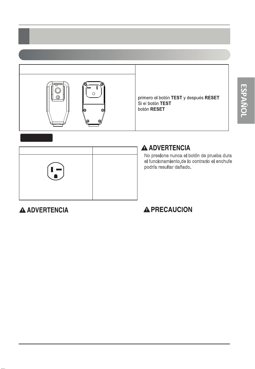
El cable de alimentación puede incluir un
dispositivo interruptor de corriente. La
carcasa del enchufe cuenta con un botón de
prueba y otro de reinicio. El dispositivo debe
comprobarse periódicamente presionando
no se desconecta o si el
suspenda el uso del aire acondicionado y
póngase en contacto con un técnico de
servicio cualificado.
No presione nunca el botón de prueba durante
el funcionamiento,de lo contrario el enchufe
podría resultar dañado.
No desmonte, modifique ni sumerja en agua
este enchufe.
Si el dispositivo se activara, deberá corregir
la causa antes de volver a utilizarlo.
Los hilos conductores dentro del cable están
rodeados por blindajes, que supervisan la
corriente de fuga.
Estos blindajes no están puestos a tierra.
Examine periódicamente el cable en busca de
cualquier daño.No utilice este producto si los
blindajes resultaran expuestos.
Evite el riesgo de descargas eléctricas;esta
unidad no puede ser reparada por el usuario
por ser resistente y a prueba de alteraciones.
Manipular la porción sellada de la unidad
anulará todas las garantías y quejas de
rendimiento.Esta unidad no
su uso
encendido-apagado.
no permanece activo,
está
como un interruptor de
.
diseñada para
Manual del Propietario 31
Page 32
Seguraida Electrica
Seguraida ElectricaSeguraida Electrica
IMPORTANTE
(FAVORLEA CON ATENCIÓN)
POR LA SEGURIDAD PERSONAL DEL USUARIO, ESTE
APARATO DEBE SER DEBÍDAMENTE NEUTRALIZADO.
El cordón de energía de éste aparato esta equipado
con tres patas(cable a tierra). Utilice éste con un
enchufe de pared de tres salidas(a tierra) para
minimizar el peligro de choque eléctrico. El cliente
debe revisar el receptor de pared y el circuito por un
electricista calificado para asegurarse que la
recepción esta debidamente neutralizada.
NO CORTE O REMUEVA LA TERCERA PATA(GROUND)
DEL ENCHUFE.
A. SITUACIONES EN LAS CUALES EL APARATO
ES DESCONECTADO OCASIONALMENTE:
Debido al peligro potencial, nosotros no
recomendamos el uso de adaptadores. Sin embargo,
si usted desea utilizar un adaptador, una CONEXIÓN
TEMPORAL, puede ser
efectuada. Utilice adaptadores UL, disponibles en la
mayoría de los estable cimientos de
herramientas. La pata mas grande del adaptador
debe ser alineada con la pata mas grande del
interruptor para asegurarse una polarización
adecuada.
Adaptar la terminal del ground del adaptador a
la cubierta de la pared con un
tornillo no neutraliza el aparato a menos que la
cubierta del tornillo sea de metal, u no sea
insolada, y el receptor de pared este
neutralizado a través del alambrado del la casa.
El cliente debe hacer verificar el circuito por un
electricista calificado para asegurarse que el
receptor esta debidamente neutralizado.
Desconecte el cordón de energía del adaptador,
utilizado una mano en cada uno. De lo contrario, la
terminal del adaptador puede romperse. NO UTILICE el
aparato con un enchufe roto.
32
B. SITUACIONES EN LAS CUALES EL APARATO
ES DESCONECTADO CON
FRECUENCIA.
No utilice un adaptador en estas circunstancias.
Desconectar el cordón de energía con frecuencia lo
llevará al eventual rompimiento de la terminal de
neutralización. La saluda de energía de la pared
debe ser reemplazada por una salida de tres
patas(neutralizada).
ADVERTENCIA:
por el Estado de California de causar cáncer y defectos
de nacimiento u otros daños reproductivos.
Lávese las manos después de manipular.
Este producto contiene quimicos conocidos
Page 33
Instalacion
Retire los materiales de embalaje del soporte de pared de
pared y la cinta del aire acondicionado.
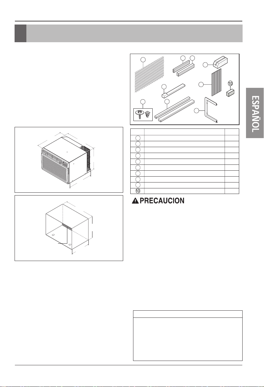
REQUISITOS DE INSTALACIÓN
Si utiliza un soporte de pared de pared ya existente,
deberá medir sus dimensiones. Instale el nuevo aire
acondicionado según estas instrucciones de instalación
para lograr el mejor funcionamiento. Todos los soporte de
pared de pared utilizados para montar el nuevo aire
acondicionado deben estar en buenas condiciones
estructuralesycontar con una rejilla trasera para conectar
el nuevo aire acondicionado de forma segura. (F
Con el soporte de pared LGE (incluido opcionalmente
con su unidad), podrá mantener el mejor rendimiento del
nuevo aire acondicionado. (Figure 2
20-3/32"
(511 mm)
Aire acondicionado
)
24"(610 mm)
18-15/32"(468 mm)
14-13/32"
(366 mm)
igure 1
Figure 1
)
HARDWARE DE INSTALACIÓN
1
8
9
ARTÍCULO
1
2
3
4
5
6
7
8
9
NOMBRE DE LAS PIEZAS Q'TY
REJILLA DE PLÁSTICO 1
TIRA VERTICAL DE AISLAMIENTO 1
TIRAS ENVOLVENTES DE AISLAMIENTO
TIRA HORIZONTAL DE AISLAMIENTO 1
BLOQUE DE APOYO 2
COMPUERTA 1
MARCO DE AJUSTE 2
CUÑ 2A
TUERCAS DE PLÁSTICO Y TORNILLOS DE ARANDELA
CORREA DE AISLAMIENTO
2 4
2 opciones de tamaño
3
7
2 opciones de tamaño
Instalacion
5
6
2
4
1
25-7/8"
(656 mm)
15-17/32"
(394 mm)
Rejilla de aluminio
Soporte de pared
LGE
16-23/32"
(425 mm)
Figure 2
SERVICIO ELÉCTRICO
Compruebe su servicio eléctrico disponible. La fuente de
alimentación disponible debe ser igual que la que se
muestra en la placa de identificación de la unidad
(encontrada en el lado izquierdo de la carcasa).
Todos los modelos están equipados con un enchufe de
tres dientes para proporcionar el servicio apropiado y
poner a tierra el positivo de fo
enchufe de ninguna manera. No utilice un enchufe
adaptador. Si su enchufe de pared actual no admite su
enchufe, llame a un electricista cualificado para realizar
las correcciones necesarias. GUARDE LA CAJA DE
CARTÓN para el almacenamientoyeste MANUAL DEL
PROPIETARIO para futuras referencias. El cartón es la
mejor manera de almacenar la unidad durante el invierno
o cuando no esté en uso.
rma segura. No cambie el
Para evitar riesgos de daños corporales, materiales, o daños
al producto debidos al peso de este dispositivo y a los bordes
afilados que pueden estar expuestos:
• Los aires acondicionados tratados en este manual
representan un peligro por peso excesivo. Son necesarias
dos o más personas para desplazar e instalar la unidad.
Para evitar lesiones o grandes esfuerzos, utilice las técnicas
de elevación y desplazamiento para mover la unidad.
• Examinar cuidadosamente la ubicación donde el aire
acondicionado vaya a ser instalado. Asegúrese de que
aguantará el peso de la unidad a lo largo de un extenso
período de tiempo.
• Manipule con cuidado el aire acondicionado. Utilice los
guantes protectores siempre que levante o desplace la
unidad. EVITE las aristas afiladas de metal de las bobinas
frontal y posterior.
• Asegúrese de que el aire acondicionado no se caiga durante
la instalación.
HERRAMIENTAS NECESARIAS:
• Guantes ceñidos
adecuados
• Destornillador estándar
• Destornillador de estrella
• Alicates
• Cuchillo afilado
• Llave inglesa abierta o
ajustable de 3/8-pulgadas
• Enchufe y carrete de tuerca
hexagonal de 1/4- pulgadas
• Cinta métrica
• Taladro eléctrico
• Boca de taladro de 1/4-
pulgadas
Manual del Propietario 33
Page 34
Instalacion
INSTALACIÓN
Recomendamos encarecidamente que desmonte el viejo
soporte de pared y la instalación de un nuevo soporte
de pared LGE.
Si decide mantener el soporte de pared existente, tendrá
que redireccionar las rejillas de ventilación en la parte
posterior de la ilustración del soporte de pared.
Recomendamos el uso de alicates. Si NO las redirecciona,
corre el riesgo de un rendimiento pobre o de averías en el
producto.
Estas no están cubiertas bajo los términos de garant
LGE.
• Escoja una ubicación que permita al aire acondicionado
soplar hacia el área que desee. Una buena instalación,
prestando especial atención a la posición correcta de la
unidad reducirá la necesidad de reparaciones.
ía de
ARTÍCULOS EN EL HARDWARE DE
INSTALACIÓN
Usted puede no necesitar todas las piezas del conjunto.
Descarte las piezas que no utilice
Rejilla plástica 26
ARTÍCULO (pulgadas) Cant.
Tira vertical de aislamiento 15
Tiras de aislamiento 67
envolventes 59
Tira horizontal de aislamiento
Bloque de apoyo 1
Compuerta 14 x 4
Cuñ 11a
Marco de ajuste 2
Tornillos de arandela 4
Tuercas (Plástico) 4
Rejilla posterior 1
Correa de aislamiento
26
5
3
5
3
/
4
9
/
16
1
/
8
27
/
3
/4
/
x 1
4
13
/
16
/
16
x 16
x 1
3
x 1
x 1
32
3
/
x 1
3
/
8
1
/
2
x 1 x
3
/
x 1 x
1
/
2
3
/
x 1
8
/
x
8
3
/
8
x 1
8
x 4
1
/
x
8
16
25
x 1
5
3
3
1
3
/
1
8
/
1
32
3
/
1
8
3
/16
1
/
2
16
1
/
2
4
/
1
4
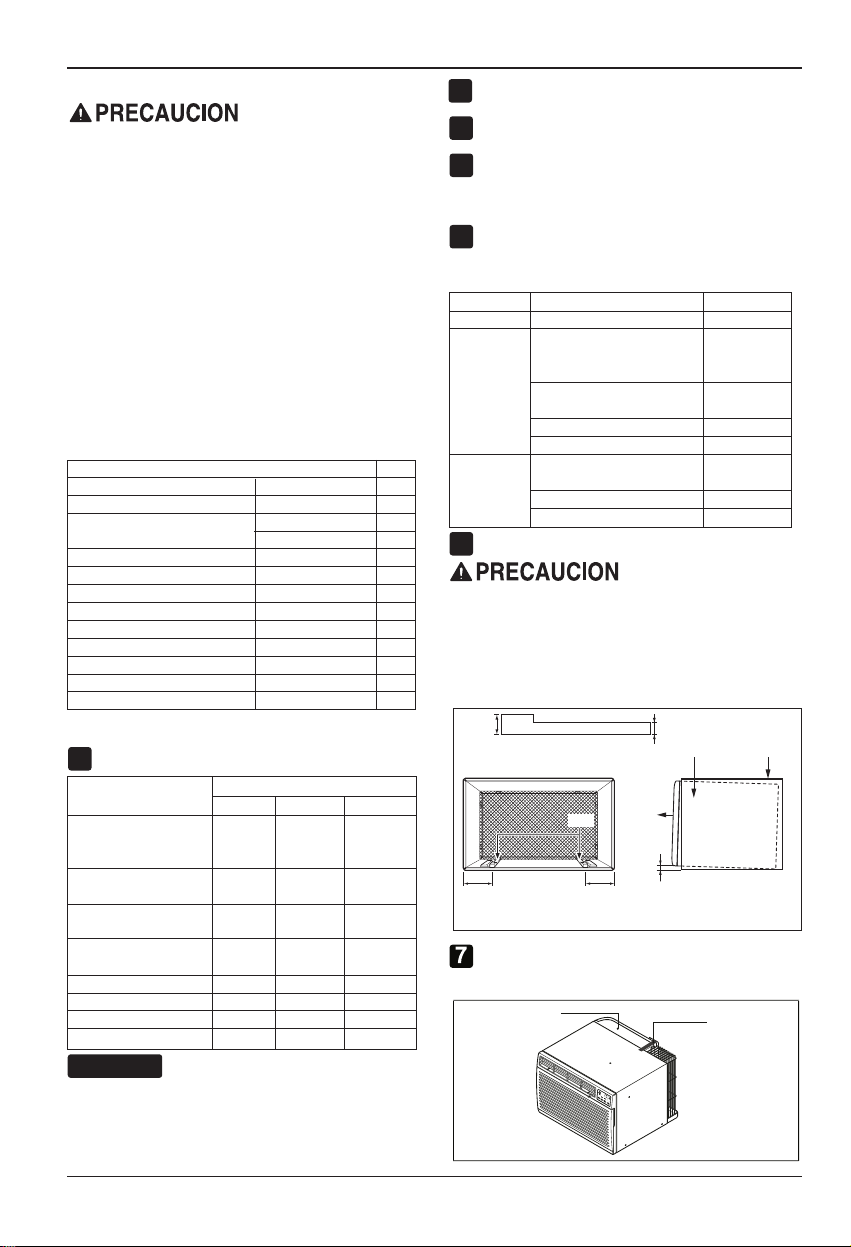
CÓMO INSTALAR
Identifique el soporte de pared existente antes de
1
instalar la unidad según la lista.
Marca
White-Westinghouse
Frigidaire
Carrier (Serie 52F)
General Electric
/Hotpoint
Whirlpool 25-7/8 16-1/2
Fedders/Emerson 27 16-3/4
LGE 25-7/8 15-17/32 16-23/32
Emerson/Fedders 26-3/4 15-3/4 15
Carrier (Serie 51S) 25-3/4 16-7/8 18-5/8
Friedrich 27 16-3/4 16-3/4
CONSEJO
Todos los soporte de pared utilizados para montar el
nuevo aire acondicionado deben estar en condiciones
estructurales sanas y tener una rejilla posterior que se
acople con seguridad al soporte de pared,ouna pestaña
posterior que sirva como freno para el aire
acondicionado.
34 Aire Acondicionador
Dimensiones del soporte de pared (pulgadas)
Ancho Altura
25-1/2 15-1/4
Profundidad
16, 17-1/2
ó 22
26 15-5/8 16-7/8
17-1/8
ó 23
16-3/4
ó 19-3/4
Desmonte el antiguo aire acondicionado del soporte
2
de pared existente.
Limpie el interior del soporte de pared existente. (No
3
toque el sellado.)
El soporte de pared se estar firmemente sujeto a la pared
4
antes de instalar el aire acondicionado. Utilice los clavos o
tornillos a través del soporte de pared, si fuera necesari
Vuelva a pintar el soporte de pared si fuera necesario.
Prepare el soporte de pared para la instalación de la
5
unidad. Si usted piensa utilizar el soporte de pared
existente,yno es LGE, utilice el procedimiento B ó C
a continuación.
Procedimiento Marca
Profundidad (pulgadas)
A LGE 16-23/32
White-Westinghouse
Frigidaire Carrier
Carrier (Serie 52F)
General Electric
B
/Hotpoint
16, 17-1/2
ó 22
16-7/8
Whirlpool 17-1/8ó23
Carrier (Serie 51S)
Fedders/Emerson
C
Emerson/Fedders 15
18-5/8
16-3/4
ó 19-3/4
Friedrich 16-3/4
6
Instale la nueva unidad en el soporte de pared.
Al finalizar la instalación, la unidad de sustitución DEBE
tener una pendiente hacia atrás según se ilustra. Para
lograr una pendiente de 1/4", retire el envoltorio de las
cuñas de 8-1/2" y acóplelas según se muestra a
continuación en la Figure. 3. Coloque el extremo más alto
de la cuña en la parte frontal de la base del soporte de
pared.
1"de
alto
Cuña
6" 6"
COLOCACIÓN DE LA CUÑA INSTALACIÓN DE LA UNIDAD
Retire la parte posterior de la correa de aislamiento
5
3
/
5 X 1 X y conéctela a la parte superior
16
3
/
/
16
4
FRENTAL
1/4"
3/4"de alto
UNIDAD
Soporte
de pared
Figure 3
de la tapa, como se muestra arriba.
tapa
aislamiento
o.
Page 35

Instalacion
Si está utilizando un nuevo soporte de pared
1
(incluido opcionalmente con su unidad), salte al
paso 3. Si no es así, instale la rejilla plástica. Corte
la rejilla plástica a 25-1/2" de ancho y 15-1/4” de
alto. Coloque la rejilla plástica en el interior del
soporte de pared en la pestaña posterior.
Apriete los 4 tornillos de la arandela para asegurar la
2
rejilla al soporte de pared. Si necesita tuercas
plásticas para montar la rejilla plástica en el interior
del soporte de pared, encontrará tuercas plásticas
en el equipo de instalación. Las tuercas están
instaladas en el interior del soporte de pared y están
presionando las perforaciones rectangulares de las
pestañas posteriores.
ó
Retire el envoltorio de la tira vertical de aislamiento
3
15-9/16 x 1-3/8 x 1-3/8 y únala a la parte interior
derecha del soporte de pared según se muestra a
continuación. Retire el envoltorio de la tira de
aislamiento envolvente de 67-1/8 x 1-3/8 x 25/32 y
únala a la parte frontal interior del soporte de pared
muestra a continuación.
según se
Interior Exterior
Aislamiento envolvente
Aislamiento vertical
9 1/2" 6"
Figure 4
Figure 5
Figure 6
Instale la nueva unidad en el soporte de pared.
4
Para el montaje, encaje la lengüeta de cada pieza
5
en la ranura de la otra pieza según se muestra a
continuación. Deslice la pieza sobre la parte frontal
del aire acondicionado hasta que el ajuste sea
rasante con el soporte de pared según se muestra a
continuación.
Ajuste (2EA)
Pared
Figure 7
• Los aires acondicionados tratados en este manual
representan un peligro por peso excesivo. Son
necesarias dos o más personas para desplazar e
instalar la unidad. Para evitar lesiones o esfuerzos
excesivos, utilice las técnicas de levantamiento y
desplazamiento apropiadas al mover la unidad.
• Manipule con cuidado el aire acondicionado, tenga
cuidado de evitar cortes de las aristas afiladas de
metal de las bobinas frontal y posterior.
• Asegúrese de que el aire acondicionado no se caiga al
desmontarlo.
• Si la unidad no funciona tras la revisión de instalación,
asegúrese que el interruptor del circuito no se ha
disparado. Consulte la guía de solución de averías
para conocer el procedimiento de reinicio.
ESPAÑOL
Manual del Propietario 35
Page 36
Instalacion
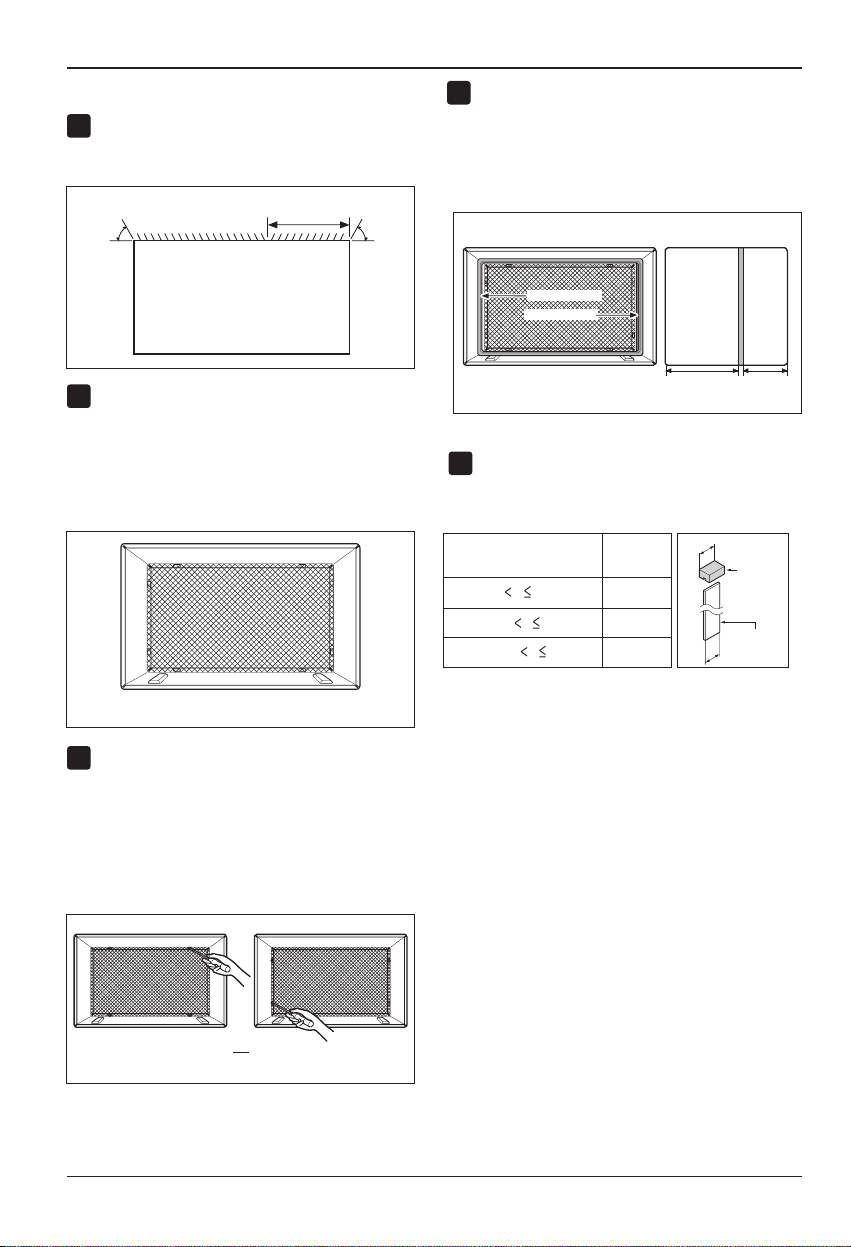
PROCEDIMIENTO B
Redireccione las rejillas de ventilación en la parte
1
posterior del soporte de pared a un ángulo de 60°
según muestra la FIG. 8. Recomendamos el uso de
alicates.
3
7
/
"
60°
Rejillas de ventilación posteriores
32
60°
Retire el envoltorio de la tira vertical de aislamiento
4
15-9/16 x 1-3/8 x 1-3/8 y únala a la parte interior
derecha del soporte de pared según se muestra a
continuación. Retire el envoltorio de la tira de
aislamiento envolvente de 67-1/8 x 1-3/8 x 25/32 y
únala a la parte frontal interior del soporte de pared
según se muestra a continuación.
Interior Exterior
(Perspectiva superior)
Si el soporte de pared ya cuenta con una rejilla
2
posterior, salte al paso 4. Si el soporte de pared no
tiene una rejilla posterior o un panel en rejilla, instale
la rejilla plástica del conjunto. Corte la rejilla plástica
a 25-1/2" de ancho y 15-1/4” de alto. Coloque la
rejilla plástica en la parte interior del soporte de
pared en la pestaña posterior.
Coloque la rejilla plástica
Apriete los 4 tornillos de la arandela para asegurar la
3
rejilla al soporte de pared. Si necesita tuercas
plásticas para montar la rejilla plástica en el interior
del soporte de pared, encontrará tuercas plásticas
en el equipo de instalación. Las tuercas están
instaladas en el interior del soporte de pared y están
presionando las perforaciones cuadradas de las
pestañas posteriores.
Figure 8
Figure 9
Aislamiento envolvente
Aislamiento vertical
9 1/2" 6"
Si la profundidad de su soporte de pared es menor o
5
igual a 18", salte al paso 6. Si no, corte las
compuertas y los bloques de soporte según la
longitud A en la tabla a continuación.
A
4
A
8
4
Longitud A
(pulgadas)
1-3/4
Profundidad D del soporte
de pared existente (pulgadas)
18 D 18-5/
18-5/
8
D 19-3/
19-3/4 D 22
3
/
4
Figure 11
Bloque
de apoyo
Compuerta
Figure 12
Apriete los tornillos
ó
36 Aire Acondicionador
Figure 10
Page 37
Manual del Propietario 37
PROCEDIMIENTO B
8
7
• Los aires acondicionados tratados en este manual
representan un peligro por peso excesivo. Son
necesarias dos o más personas para desplazar e
instalar la unidad.
Para evitar lesiones o esfuerzos excesivos, utilice
las técnicas de levantamiento y desplazamiento
apropiadas al mover la unidad.
• Manipule con cuidado el aire acondicionado, tenga
cuidado de evitar cortes de las aristas afiladas de
metal de las bobinas frontal y posterior.
• Asegúrese de que el aire acondicionado no se
caiga al desmontarlo.
• Si la unidad no funciona tras la revisiónde
instalación, asegúrese que el interruptor del circuito
no se ha disparado. Consulte la guíadesoluciónde
averías para conocer el procedimiento de reinicio.
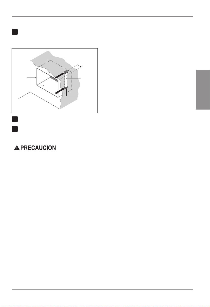
Retire el envoltorio de los bloques de apoyo y
6
acóplelos al interior del soporte de pared como
ranuras de los bloques de apoyo.
Pared
Soporte
de pared
3
(
7
"
/
32
Compuerta
Instalacion
sal ne atreupmoc al ecilseD .31 erugiF al artseum
)
ESPAÑOL
Frontal
Instale la nueva unidad en el soporte de pared.
Ajuste la posición según describe el paso 5,
procedimiento A.
Bloque
de apoyo
Figure 13
Page 38
Instalacion
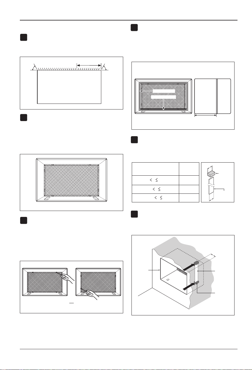
PROCEDIMIENTO C
Redireccione las rejillas de ventilación en la parte
1
posterior del soporte de pared a un ángulo de 60°
según muestra la Figure 14. Recomendamos el
uso de alicates.
3
7
"
/
60°
Rejillas de ventilación posteriores
(Perspectiva superior)
Si el soporte de pared ya cuenta con una rejilla
2
posterior, salte al paso 4. Si el soporte de pared no
tiene una rejilla posterior o un panel en rejilla, instale
la rejilla plástica del conjunto. Corte la rejilla plástica
a 26-1/2" de ancho y 15-1/2” de alto. Coloque la
rejilla plástica en la parte interior del soporte de
pared en la pestaña posterior.
Coloque la rejilla plástica
Apriete los 4 tornillos de la arandela para asegurar la
3
rejilla al soporte de pared. Si necesita tuercas
plásticas para montar la rejilla plástica en el interior
del soporte de pared, encontrará tuercas plásticas
en el equipo de instalación. Las tuercas están
instaladas en el interior del soporte de pared y están
presionando las perforaciones cuadradas de las
pestañas posteriores.
32
60°
Figure 14
Figure 15
Retire el envoltorio de la tira horizontal de aislamiento
4
de 26-3/4 x 1-3/8 x 1-3/1
6 y únala a la parte interior
derecha del soporte de pared según se muestra a
continuación. Retire el envoltorio de la tira de
aislamiento envolvente de 59-27/32x1-3/8 x 1-3/8 y
únala a la parte frontal interior del soporte de pared
según se muestra a continuación.
Interior Exterior
Aislamiento envolvente
Aislamiento horizontal
8 1/2"
Figure 17
Si la profundidad de su soporte de pared es menor o
5
igual a 18", salte al paso 7. Si no, corte las
compuertas y los bloques de apoyo según la longitud
"A" en la tabla a continuación.
A
4
A
8
4
Longitud "A"
(pulgadas)
3
/
1-3/4
4
Profundidad "D" del soporte
de pared existente (pulgadas)
18 D 18-5/
8
18-5/
D 19-3/
19-3/4 D 22
Retire el envoltorio de los bloques de apoyoyúnalos
6
al interior del soporte de pared como muestra la FIG.
19. Deslice la compuerta dentro de las ranuras en
los bloques de apoyo.
Pared
(7
Bloque
de apoyo
Compuerta
Figure 18
3
/
")
32
ó
Apriete los tornillos
38 Aire Acondicionador
Figure 16
Soporte
de pared
Frontal
Compuerta
Bloque
de poyo
Figure 19
Page 39
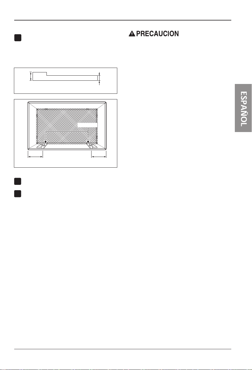
PROCEDIMIENTO C
Para lograr una pendiente de posterior para el
7
drenaje de la unidad, retire el envoltorio de las
cuñas de 11-13/16" y acóplelas según se muestra
a continuación en la FIG. 21. Coloque el extremo
más alto de la cuña en la parte frontal de la base
del soporte de pared.
1" de
alto
Cuña (2EA)
6" 6"
Instale la nueva unidad en el soporte de pared.
8
Monte el ajuste según lo descrito en el paso 6,
9
procedimiento A.
3/4"
de alto
Figure 20
Figure 21
Instalacion
• Los aires acondicionados tratados en este manual
representan un peligro por peso excesivo. Son
necesarias dos o más personas para desplazar e
instalar la unidad.
Para evitar lesionesoesfuerzos excesivos, utilice
las técnicas de levantamiento y desplazamiento
apropiadas al mover la unidad.
• Manipule con cuidado el aire acondicionado, tenga
cuidado de evitar cortes de las aristas afiladas de
metal de las bobinas frontal y posterior.
• Asegúrese de que el aire acondicionado no se
caiga al desmontarlo.
• Si la unidad no funciona tras la revisión de
instalación, asegúrese que el interruptor del circuito
no se ha disparado. Consulte la guía de solución
de averías para conocer el procedimiento de
reinicio.
Manual del Propietario 39
Page 40
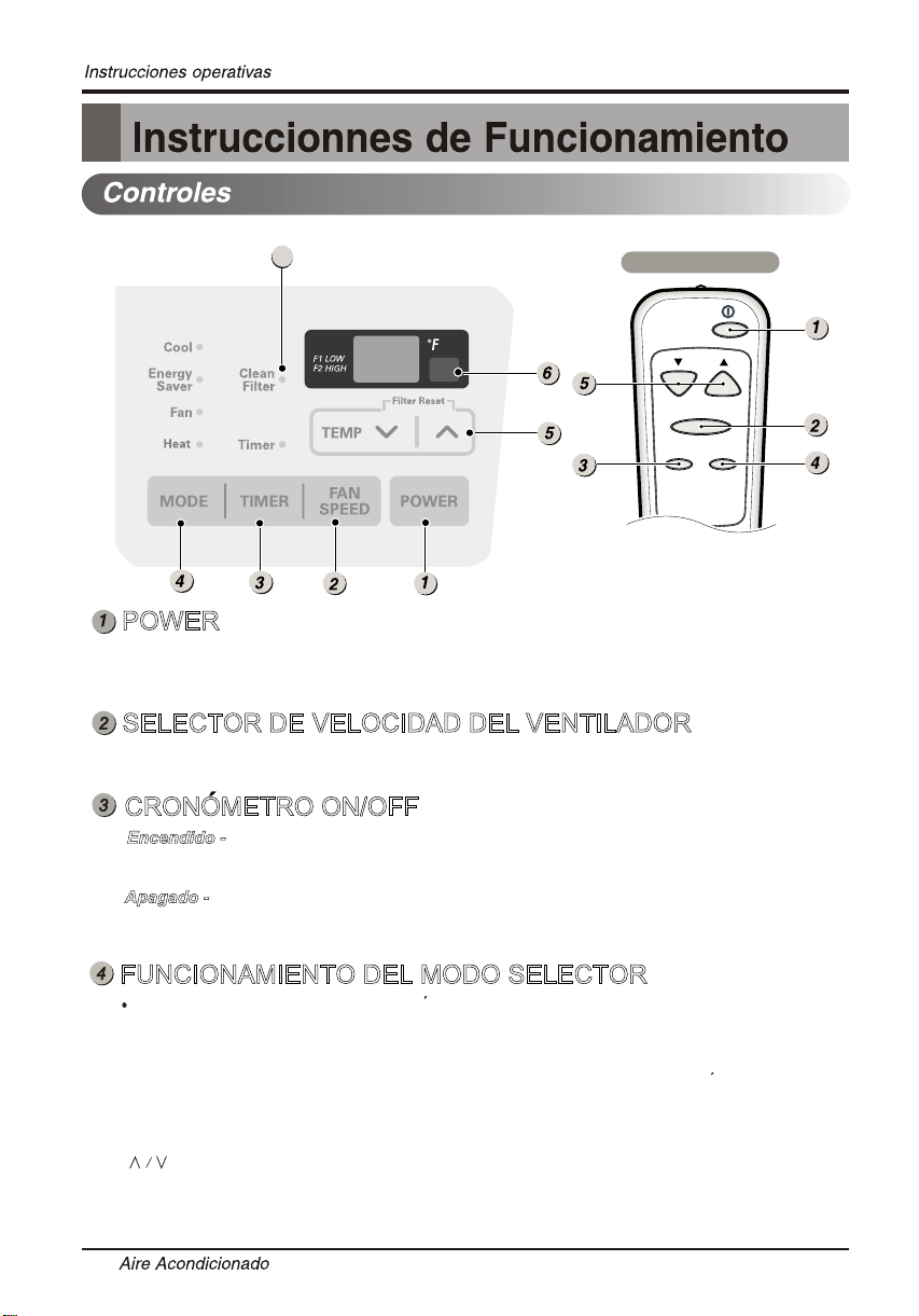
7
REMOTE CONTROLLER
Temp
Fan Speed
Timer Mode
POWER
El funcionamiento se inicia cuando se pulsa esta tecla y se detiene cuando se la
presiona nuevamente.
SELECTOR DE VELOCIDAD DEL VENTILADOR
Usado para ajustar la velocidad del ventilador a Low(F1), High (F2).
CRONOMETRO ON/OFF
Encendido - Cuando el acondicionador de aire esta apagado,puede ajustarse para
que se encienda automaticamente dentro de 1 a 24 horas en el nivel previo.
Apagado -
que se apague automaticamente dentro de 1 a 24 horas.
Cuando el acondicionador de aire esta apagado,puede ajustarse para
FUNCIONAMIENTO DEL MODO SELECTOR
Pulse el botón MODE (Modo) para desplazarse entre Ahorro de Energía / Frío /
Ventilador / calentar.
Energy Saver(Ahorro de Energía)-
sigue enfriando.
necesitara verificar la temperatura del cuarto para saber si es necesario mas enfriamiento.
Cool(frío) - El compresor funciona y enfría la habitación. Use los
y FAN(ventilador)
circulación del ventilador.
Aporximadamente cada 3minutos el ventilador se encendera,y
para configurar la temperatura deseada y la velocidad de
40
El ventilador se detiene cuando el compressor no
botones TEMP/TIMER
Page 41
(ventilador) - El ventilador hace circular el aire pero el compresor no funciona.
CONSEJO
CONSEJO
FAN
no funciona.Utilice el botón FAN(ventilador) para configurar la velocidad deseada
del ventilador.
HEAT (CALENTAR) - El calentar funciona y calentar la habitación.
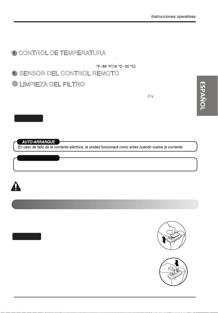
CONTROL DE TEMPERATURA
El termostato monitorea la temperature de la habitacion para mantener la temperatura deseada.
El termostato puede ser colocado entre 60
.
SENSOR DEL CONTROL REMOTO
7
LIMPIEZA DEL FILTRO
El LED “Clean Filter” (Limpiar filtro) se iluminará para avisarle que hay que limpiar el filtro.
Después de limpiar el filtro, pulse simultáneamente los botones “Temp ” para apagar
la luz “Clean Filter”.
(El reinicio del filtro debe hacerse desde el panel de control de la unidad, no desde el
mando a distancia).
Esta funcionalidad es un recordatorio para limpiar el Filtro de Aire (Consulte Mantenimiento) para un
funcionamiento más eficiente.
La luz LED se iluminará después de 250 horas de funcionamiento.
AHORRADOR DE ENEERGIA
La unidad pasa de forma predeterminada al modo de Ahorro de Energía cada vez que la unidad
se enciende, excepto al restaurarse después de una falla de la energía eléctrica.
PRECAUTION: El mando a distancia no funcionará correctamente si
una luz fuerte hace contacto con el sensor del aire acondicionado o si
hay obsáculos entre el mando a distancia y el aire acondicionado.
Insertar las baterías del control remoto
1. Empuje hacia afuera con su pulgar la cubierta en la parte posterior del
control remoto.
2. Preste atención a la polaridad e inserte nuevas batería AAA 1,5 V .
3. Vuelva a colocar la cubierta
No use batería recargables. Asegúrese que ambas baterías sean nuevas.
No mezcle las pilas alcalinas, estándares(Carbon-zinc) o
recargables(Niquel-cadmium).
• Para evitar que se descarguen, quite las baterías del control remoto si el
acondicionador de aire no va a ser usado por un período largo de tiempo.
Mantenga el control remoto lejos de los lugares húmedos o
extremadamente calientes. Para mantener el funcionamiento óptimo del
control remoto, el sensor remoto no debe exponerse a la luz solar directa.
Manual del Propietario 41
Page 42
42 Aire Acondicionador
Instruccionnes de Funcionamiento
Page 43
Cuidado y Mantenimiento
MODE TIMER POWER
FAN
SPEED
Fan
Energy
Saver
Cool
Timer
TEMP
'
F
F1 LOW
F2 MED
F3 HIGH
Cuidado y Mantenimiento
APAGUE EL ACONDICIONADOR DE AIRE Y DESENCHÚFELO DE LA FUENTE DE PODER.
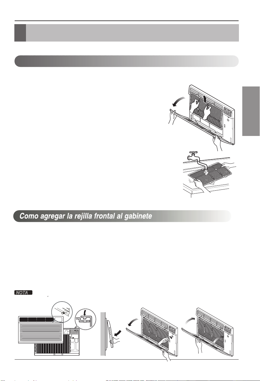
Limpieza del filtro de aire
El filtro de aire debe ser controlado al menos dos veces al mes para ver si es necesaria su
limpieza.
Las partículas atrapadas en el filtro pueden acumularse y
bloquear el flujo del aire. Esto reduce la capacidad de
refrigeración y también causa una acumulación de hielo
en los sepentines de enfriamiento.
Si el filtro se inutiliza o se daña, debe ser reemplazado
inmediatamente. Filtros de repuesto están disponibles en la
tienda donde lo compró, el representante y en los centros de
servicios autorizados.
1. Abra la rejilla de entrada hacia abajo tirando de la parte
superior de la rejilla de entrada.
2. Quite el filtro de aire de la rejilla frontal tirando ligeramente
del filtro de aire.
3. Lave el filtro usando agua tibia por debajo de 40 °C
(104 °F).
4. Sacuda suavemente el exceso de agua del filtro.
Reemplace el filtro.
ESPAÑOL
La rejilla frontal puede quitarse para su limpieza o para comprobar el modelo y el número de
seri
e.
Para su seguridad, debe seguir el siguiente procedimiento para colocarla.
1. Quite la parte superior de la rejilla frontal de
la parte superior del gabinete.
2. Empuje los extremos frontales de la rejilla
4. Ajuste los tornillos a través de la rejilla frontal
en la placa de la caja de control.
5. Cierre la rejilla de entrada.
hacia el gabineteafin de insertar las
pestañas de la rejilla frontal en el gabinete.
3. Abra la rejilla de entrada.
Guie la palanca cuidadosamente
NOTA
a traves de la parrilla mientras la empuja.
Manual del Propietario 43
Page 44

1-800-243-000.
Sonidos normales
Traqueteo agudo
Los compresores modernos de alto
rendimiento pueden presentar un
traqueteo agudo durante el ciclo
de enfriado.
Goteo o chapoteo
Las gotas de agua que caen sobre
el condensador durante la normal
operación del producto pueden
producir sonidos de "goteo o
chapoteo".
Sonido de ráfagas de aire
Delante de la unidad, puede oír
el sonido de ráfagas de aire que
son movidas por el ventilador.
Borboteo/Siseo
Un sonido parecido a un "borboteo
o siseo" puede escucharse debido
al refrigerante pasando a través
del evaporador durante una
normal operación.
44
Vibración
La unidad puede vibrar y hacer
ruido debido a una estructura débil
de la pared o la ventana, o a una
instalación incorrecta.
Page 45
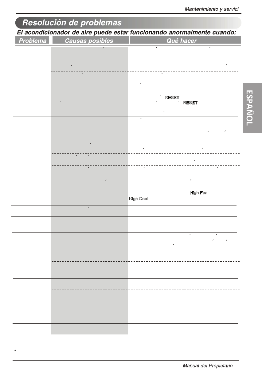
El aire
acondiciona do
no enciende
El aire
acondiciona do no
enfr’a corno
debiera
El aire
acondiciona do
enfria dernasiado
Hay goteo de agua
en la parte externa
Hay goteo de
aguaen la parte
interna
Se acumula agua
en la bandeja
El aparato de aire
acondicionado se
enciende y apaga
rápidamente.
Se escuchan
ruidos cuando el
equipo está
operando.
El sensor remoto
se desactiva de
manera prematura
Estancia
demasiado fría.
El aire acondicionado esta
desconectado.
El fusible esta quemado/el interruptor
de energia se habloqueado.
Falta de energia.
El dispositivo interruptor de corriente
esta desconectado.
El flujo de aire esta restringido.
Coloque el control de TEMPERATURA
en un numero mas alto.
El filtro de aire esta sucio.
El cuarto aun esta caliente.
El aire frio se esta escapando.
El serpentin de refrigeracion se ha
congelado.
El hielo bloquea el flujo de aire y
detiene el enfriamiento del cuarto.
Clima caliente y humedo.
El acondicionador de aire no esta
inclinado hacia el exterior.
Se elimino la humedad del aire y se
drena en la bandeja.
Filtro de aire sucio - flujo de aire
restringido.
La temperatura exterior es
extremadamente cálida.
Suena el movimiento del aire.
Vibración de la ventana - instalación
defectuosa.
El control remoto no está en el rango
de alcance.
La señal del control remoto está
obstruida.
La temperatura está demasiado baja.
Asegurese que ei aire acondicionado esta conectado
completamente a la fuente de energia.
Cheque los fusibles/interruptor de la casa y reemplace
los fuslbles o reestablezca el interruptor de energia.
Cuando la energia se reestablezca
para encender de nuevo el aire acondicionado.Con
esto evitara que se produzca una sobrecarga en
el compresor.
Presione el boton
de alimentacion Si el boton
suspenda el uso del aure acondicionado y pongase en
contacto con un tecnico de servicio cualificado.
Asegurese que no haya cortinas,persianas o muebles
bloqueando el frente del aire acondicionado.
Ajustar el control de temperatura a un numero mas bajo.
Limipe el filtro pro lo menos cada dos semanas.Vea la
seccion de instrucciones de operacion.
Cuando usted enciende el aire acondicionado debe esperar
un momento para que la habitacion se enftre.
Asegurese que todas las salidas de aire esten cerradas
para que el aire regrese.
Establezca una temperatura mas alta.
Elija el modo alto del ventilador High Fan
High Cool
Esto es normal.
.
Para una salida correcta del agua ,asegurese de que el
acondicionador de aire se incline levemente desde la
parte frontal hasta la parte trasera de la caja.
Esto es normal durante un periodo corto en areas con
poca humedad ;es normal durante un periodo mas
largo en areas muy humedas.
Limpie el filtro.
Establezca el ventilador en una velocidad más alta para
conseguir que el aire circule más rápidamente por el
circuito refrigerador.
Esto es normal. Si está muy fuerte, ajuste el FAN
(ventilador) a una velocidad más baja.
Consulte las instrucciones de montaje o al instalador.
Ubique el control remoto dentro de un rango de 20 pies y
en un ángulo de 120º desde el frontal de la unidad.
Remueva la obstrucción.
Seleccione una temperatura más alta.
situado en el enchufe del cable
RESET
espere 3 minutos
,
RESET
no p ermanece activo,
o enfriado alto
Si aparece "CH" en la pantalla, por favor llame al 1-800-243-0000.
45
Page 46

WARRANTY
LG ROOM AIR CONDITIONER LIMITED WARRANTY - USA
WH
AT THIS WARRANTY COVERS:
LG Electronics U.S.A., Inc. (“LG”) warrants your LG Room Air Conditioner ("product") against defect in materials or workmanship
under normal household use, during the warranty period set forth below, LG will, at its option, repair or replace the product. This
limited warranty is valid only to the original retail purchaser of the product, is not assignable or transferrable to any subsequent
purchaser or user, and applies only when the product is purchased through an LG authorized dealer or distributor and used within
the United States (“U.S.”) including U.S. Territories.
Note: Replacement produc
of the original unit’s warranty period or ninety (90) days, whichever is longer. Please retain dated receipt or delivery ticket as
evidence of the Date of Purchase for proof of warranty (you may be required to submit a copy to LG or authorized representative).
WARRANTY PERIOD:
1 year from the Date of Purchase: Any
ts and repair parts may be new or factory-remanufactured and are warranted for the remaining portion
internal/ functional Parts and Labor.
HOW SERVIC
In-home service will be provided during the warranty period subject to availability within the United States. In-home service may
not be availa
during in-home service repair cannot be completed, it may be necessary to remove, repair and return the product. If in-home
service is unavailable, LG may elect, at our option, to provide for transportation of our choice to and from a LG authorized service
center.
THIS LIM
1. Ser
for instruction on product use.
2. Replacing house fuses or resetting of circuit breakers,
correction of house wiring or plumbing, or correction of
product installation.
3. Damage or failure caused by leaky/ broken/ frozen water
pipes, restricted drain lines, inadequate or interrupted
water supply or inadequate supply of air.
4. Damage or failure caused by accidents, pests and vermin,
lightning, wind, fire, floods or acts of God.
5. Damage or failur
installation, repair or maintenance. Improper repair
includes use of parts not approved or specified by LG.
6. Damage or failure caused by unauthorized modification or
alteration to the product.
7. Damage or failure caused by incorrect electrical current,
voltage, or plumbing codes.
THIS
WARRANTY IS IN LIEU OF ANY OTHER WARRANTY, EXPRESS OR IMPLIED, INCLUDING AND WITHOUT LIMITATION TO, ANY
WARRANTY OF MERCHANTABILITY OR FITNESS FOR A PARTICULAR PURPOSE. TO THE EXTENT ANY IMPLIED WARRANTY IS
REQUIRED BY LAW, THIS WARRANTY IS LIMITED IN DURATION TO THE TERM PERIOD EXPRESSED ABOVE. REPAIR OR
REPLACEMENT AS PROVIDED UNDER THIS WARRANTY IS THE EXCLUSIVE REMEDY FOR THE CUSTOMER. NEITHER THE
MANUFACTURER NOR ITS U.S. DISTRIBUTOR SHALL BE LIABLE FOR ANY INCIDENTAL, CONSEQUENTIAL, INDIRECT, SPECIAL, OR
PUNITIVE DAMAGES OF ANY NATURE, INCLUDING AND WITHOUT LIMITATION TO, LOST REVENUES OR
DAMAGE, WHETHER BASED IN
E IS HANDLED: In-Home Service
ble in all areas. To receive in-home service, the product must be unobstructed and accessible to service personnel. If
ITED WARRANTY DOES NOT COVER:
vice trips to deliver, pick up, or install the product or
e resulting from misuse, abuse, improper
CONTRACT, TORT, OR OTHERWISE.
8. Cosmetic damage, including scratches, dents, chips or
other damage to the finish of the product, unless such
damage results from defects in materials or
workmanship and is reported to LG within seven (7)
calendar days from the date of delivery.
9. Damage or missing items to any display, open box,
discounted, or refurbished product.
10. Product where the original factory serial numbers have
been removed, defaced or changed in any way.
11. Repairs when product is used in other than normal and
usual household use (e.g. rental, commercial use,
offices, or recreational facilities) or contrary to the
instructions outlined in the owner’s manual.
12. The removal and reinstallation of the Product if it is
installed in a
n inaccessible location.
PROFITS, OR ANY OTHER
SOME STATES DO NOT ALLOW THE EXCLUSION OR LIMITATION OF INCIDENTAL OR CONSEQUENTIAL DAMAGES OR LIMITATIONS
ON HOW LONG AN IMPLIED WARRANTY LASTS, SO THE ABOVE EXCLUSION OR LIMITATION MAY NOT APPLY TO YOU. THIS
WARRANTY GIVES YOU SPECIFIC LEGAL RIGHTS AND YOU MAY ALSO HAVE OTHER RIGHTS THAT VARY FROM STATE TO STATE.
HOW TO OBTAIN WARRANTY SERVICE & ADDITIONAL INFORMATION:
Call 1-800-243-0000 or visit our website at www.lg.com
Mail to: LG Customer Information Center (ATTN: CIC)
201 James Record Road, Huntsville, AL 35824
.
Page 47

Garantía
GARANTÍA LIMITADA DEL AIRE ACONDICIONADO LG - EE.UU.
COBERTURA DE LA GARANTÍA:
LG Electronics Inc. (“LG”) garantiza que reparará o sustituirá, gratuitamente, su producto si resulta defectuoso en materiales o
mano de obra bajo condiciones normales de uso durante el periodo de garantía mencionado más abajo, efectivo a partir de
la fecha de compra del producto original por parte del consumidor. Esta garantía limitada sólo es válida para el comprador
original del producto y no es asignable ni transferible a ningún otro comprador o usuario final subsecuentes, y efectiva
únicamente cuando el producto se compra a través de un distribuidor autorizado de LG y se utiliza en los Estados Unidos ("EE
UU") o en cualquiera d
Nota: Los recambios y piezas de repuesto pueden ser nuevos o estar reconstruidos de fábrica y están garantizados durante el
tiempo restante del periodo de garantía de la unidad original o noventa días (90), el periodo de los dos que sea más largo. Por
favor, guarde el recibo de compra o la nota de entrega como prueba de la fecha de compra como comprobante de garantía (se le
puede pedir que presente una copia a LG o a su representante autorizado).
PERIODO DE GARANTÍA:
1 año desde la fecha de compra: Cualquier repuesto interno/funcional y mano de obra
e sus territorios.
PROCESO DE S
Los servicios a domicilio se prestarán durante el periodo de garantía sujeto a disponibilidad en los Estados Unidos. El servicio a
domicilio puede no estar disponible en todas las áreas. Para recibir asistencia técnica a domicilio, el producto debe estar en un
entorno despejado y accesible al personal técnico. Si durante el servicio a domicilio la reparación no se puede llevar a cabo, es
posible que sea necesario desplazarlo a nuestras instalaciones, repararlo y devolverlo a su hogar. Si este fuera el caso, LG puede
optar, a petición nuestra, a utilizar el transporte de n
autorizado de LG.
ESTA GARANTÍA LIMITADA NO SE APLICA A:
1. Las visitas de Asistencia a domicilio para entregar, recoger
y/o instalar el producto, instruir o sustituir fusibles.
2. Sustitución de fusibles de la casa o reajuste de
interruptores de circuito, la corrección del cableado de la casa
o de la tubería, o la corrección de la instalación del producto.
3. Los daños o averías causa
congelación de tuberías de agua, líneas de drenaje restringido,
suministro insuficiente de agua o interrumpido, o suministro
insuficiente de aire.
4. Los daños o averías causados por accidentes, plagas e
insectos, rayos, viento, fuego, inundaciones o actos de Dios.
5. Los daños o fallos ocasionados por el mal uso, abuso,
instalación inadecuada, reparación o mantenimiento. Se
considera reparación inadecuada aquella en que se hayan
utilizado piezas no aprobadas o especificadas por LG.
6. Los daños o averías causados por modificaciones no
autorizadas o alteraciones del producto.
7. Los daños o averías causados por la u
corriente eléctrica, tensión o código de plomería incorrectos.
ESTA GARANTÍA SE OTORGA EN SUSTITUCIÓN O EXCLUSIÓN DE TODA OTRA GARANTÍA, EXPRESA O IMPLÍCITA, INCLUYENDO SIN
LIMITAR CUALQUIER GARANTÍA DE CALIDAD O IDONEIDAD CON UN PROPÓSITO CONCRETO. EN LA MEDIDA EN QUE CUALQUIER
GARANTÍA IMPLÍCITA ES OBLIGADA POR
REPARACIÓN O REEMPLAZO DE PIEZAS, SEGÚN LO ESTABLECIDO EN ESTA GARANTÍA, ES EL ÚNICO QUE PUEDE RECLAMAR EL
CLIENTE. NI EL FABRICANTE NI SU DISTRIBUIDOR EN LOS EE.UU. SE HACE RESPONSABLE DE CUALQUIER DAÑO (DERIVADO,
INDIRECTO, ESPECIAL O PENAL) DE CUALQUIER NATURALEZA, INCLUYENDO, SIN LIMITACION, LA PÉRDIDA DE INGRESOS O
BENEFICIOS O CUALQUIER OTRO TIPO DE DAÑO, AÚN BASADO EN UN CONTRATO, SEA UN AGRAVIO O DE CUALQUIER OTRA
MANERA.
ERVICIO: Servicio a domicilio
dos por fugas / roturas/
tilización de una
LA LEY, ESTÁ LIMITADA EN DURACIÓN AL PERIODO DE GARANTÍA YA MENCIONADO. LA
uestra elección para desplazar la unidad al y del centro de servicio
8. Daños estéticos, incluyendo arañazos, abolladuras,
desportilladuras u otros daños en el acabado del producto, a
menos que dichos daños sean el resultado de defectos en los
materiales o mano de obra y se informe a LG en el plazo de
siete días naturales (7) a partir de la fecha de entrega.
9. Los daños o la pérdida de componentes de cualquier
producto cuya caja haya sido abierta, haya sido objeto de un
descuento o se haya restaurado.
10. Los productos cuyos números de serie de fábrica
originales hayan sido quitados, borrados o cambiados de
ninguna manera.
. Las reparaciones cuando el producto se utiliza para
11
cualquier cosa fuera de lo normal y del uso doméstico
habitual (por ejemplo su alquiler, uso comercial, en oficinas o
en instalaciones de ocio) o en contra de la instrucciones que
se indican en el manual del propietario.
12. La extracción y reinstalación del producto si está instalado
en un lugar inaccesible.
ALGUNOS ESTADOS NO PERMITEN LA EXCLUSIÓN O LIMITACIÓN DE DAÑOS IMPREVISTOS O RESULTANTES, O LIMITACIONES A LA
DURACIÓN DE LAS GARANTÍAS IMPLÍCITAS, POR LO QUE LA EXCLUSIÓN O LIMITACIÓN MENCIONADA ANTERIORMENTE NO SERÁ
APLICABLE AL USUARIO. ESTA GARANTÍA LE OTORGA DERECHOS LEGALES ESPECÍFICOS Y TAMBIÉN PUEDE TENER OTR
VARIARÁN DE UN ESTADO A OTRO.
OS QUE
COMO OBTENER EL SERVICIO DE ESTA GARANTÍA E INFORMACIÓN ADICIONAL:
Llame al 1-800-243-0000 o visite nuestra página web: www.lg.com.
Dirección de correo ordinario: LG Customer Information Center (ATTN: CIC)
201 James Record Road, Huntsville, AL 35824
Page 48

LG ELECTRONICS,INC.
1000 Sylvan Ave.,Englewood Cliffs,NJ 07632
LG Customer Information Center
1-800-243-0000
Register your product Online!
www.lg.com
 Loading...