

LG LSXS26466 Series, LSXS26366 Series, LSXS26386 Series, LSXS26326 Series, LSXC22386 Service Manual
...
REFRIGERATOR
SERVICE MANUAL
CAUTION
PLEASE READ CAREFULLY THE SAFETY PRECAUTIONS OF THIS MANUAL
BEFORE CHECKING OR OPERATING THE REFRIGERATOR.
MODELS:
LSXS26466
LSXS26386
LSXS26366
LSXS26326
*
*
*
*

CONTENTSCONTENTS
SAFETY PRECAUTIONS ................................................................................................ ............................ 3
1. SPECIFICATIONS .......................................................................................... .......................................... 4
2. PARTS IDENTIFICATION ......................................................................... ............................................... 5
3. DISASSEMBLY ................................................................................................. ....................................... 6
1. Door Alignment.......................................................................................................................................... 6
2. Install Water Filter...................................................................................................................................... 7
3. Refrigerator Shelves.................................................................................................................................. 7
4. Icemaker.................................................................................................................................................... 8
4. HOW TO DISASSEMBLY AND ASSEMBLY................................................ ............................................ 9
1. Removing and Replacing Refrigerator door.............................................................................................. 9
2. Handle Removal........................................................................................................................................ 10
3. Redd S/W.................................................................................................................................................. 11
4. Removing and Replacing Refrigerator and Freezer Led’s........................................................................ 11
5. Fan Shroud Grille....................................................................................................................................... 12
6. Water Valve Tubes Assembly Method....................................................................................................... 13
7. Way Valve Service..................................................................................................................................... 14
8. Dispenser .................................................................................................................................................. 15
9. Disassembly of Fan Motor ………………………………………………………………………………………. 17
5. MICOM FUNCTION ................................................................................................ ................................. 18
6. ICEMAKER AND DISPENSER WORKING PRINCIPLES AND REPAIR................................................ 26
1. Working Principles..................................................................................................................................... 26
2. Function on Icemaker................................................................................................................................ 27
3. Ice maker Troubleshooting........................................................................................................................ 30
4. Icemaker Circuit........................................................................................................................................ 31
7. CIRCUIT DIAGRAM................................................................................... ............................................... 32
8. TROUBLE DIAGNOSIS.......................................................... .................................................................. 33
9. PCB ………………………………………………………………………………………………………….......... 55
10. TROUBLESHOOTING WITH ERROR DISPLAY ……………………………………………………....…… 56
11. TROUBLESHOOTING WITHOUT ERROR DISPLAY ……………………………………………………… 74
12. EXPLODED VIEW .................................................................................................................................106
Safety Warning and Cautions
Chapter 1 Safety Warning and Cautions
► Observing cautions for safety can prevent accidents and dangers.
► Cautions are classified into Warning and Caution and the meanings are as follows
WARNING
WARNING indicates the possibility of serious injury or death if the
instructions are not followed.
CAUTION
Caution indicates a hazardous situation with the possibility of product
damage or personal injury if the instructions are not followed
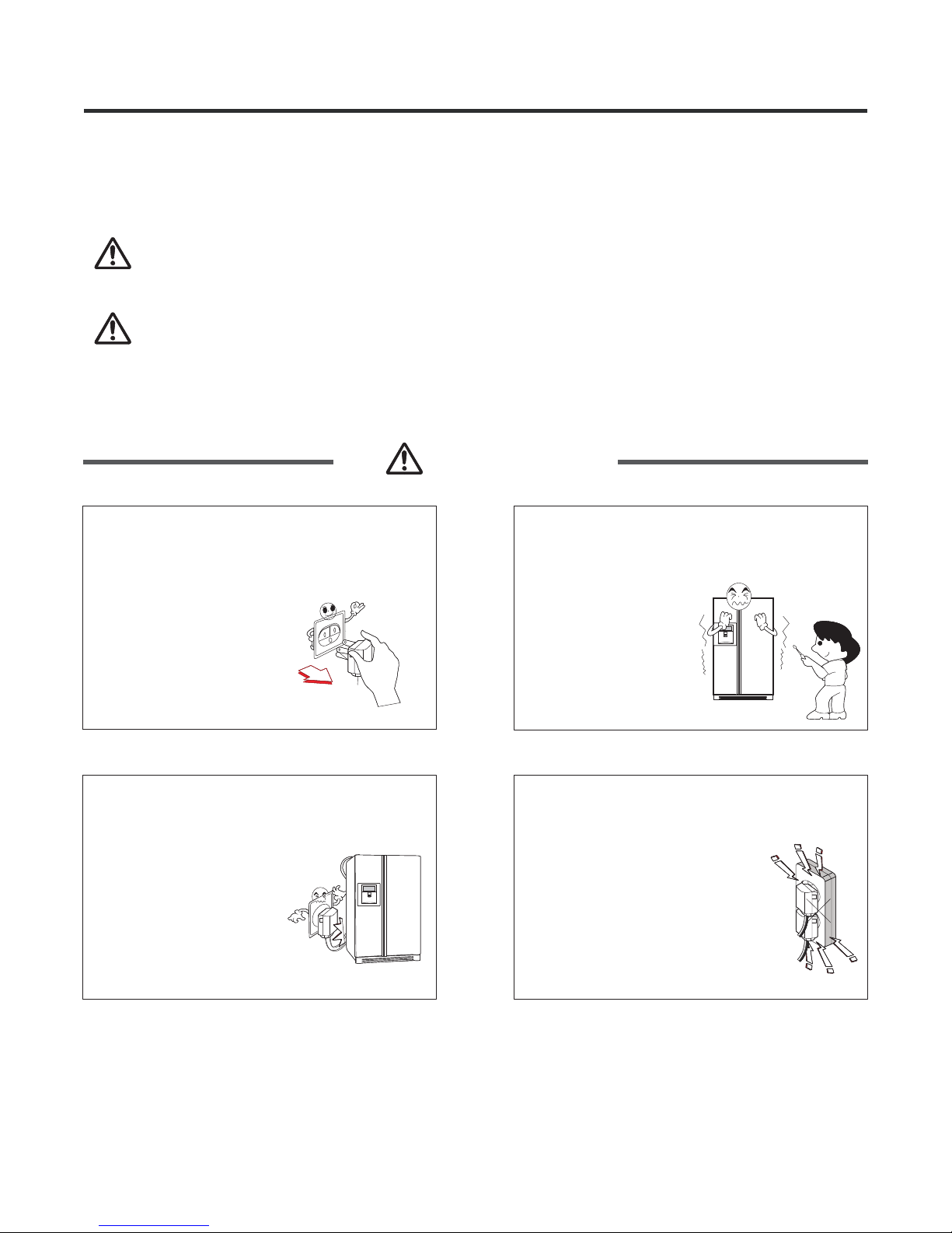
WARNING
Be cautious of electric shock.
Control board (PWB Main and Sub)
uses power supply of about 120 VAC.
Be sure the plug and cord are not
pressed by the rear side of the
refrigerator.
Damage to power plugs
could result in fire or
electric shock.
Do not allow consumers to directly
repair, disassemble, or modify the
refrigerator.
Harm, electric shock,
or fire could occur.
Plug the refrigerator into a
dedicated circuit.
Plugging in too many appliances
can result in fire or problems with
the operation of your refrigerator.
Safety Warning and Cautions
WARNING
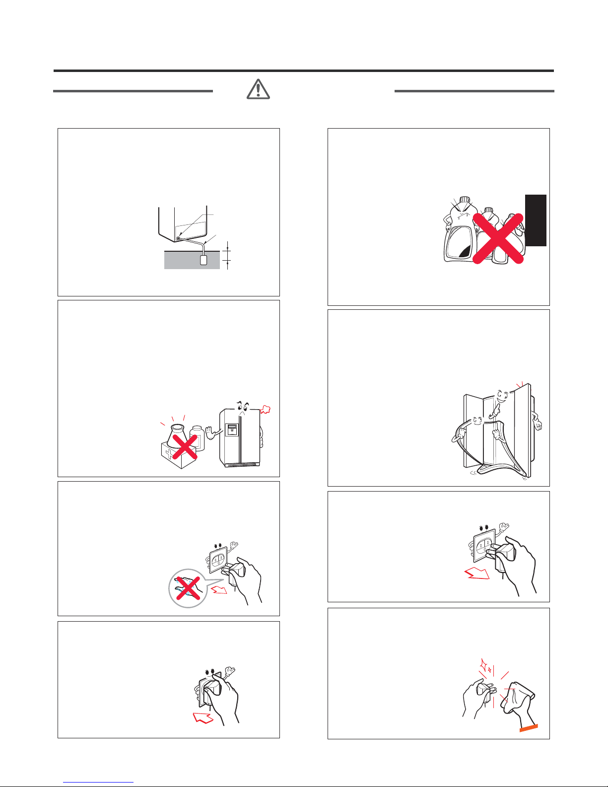
If grounding is required, be sure to
consult an electrician.
The refrigerator
must be plugged in
to a properly rated
and grounded
outlet. If you are
not sure of your
voltage or ground,
consult a qualified
and licensed
electrician.
Copper
plate
Grounding nut
Grounding wire
More than
75cm
Do not store medications or
biohazardous products requiring
precise temperature control.
Do not use the refrigerator to store
papers, electronic storage media,
or similar items.
The refrigerator is
for storing food.
This is a consumer
household
appliance and not a
precision device.
Do not store poisonous,
flammable, or explosive chemicals
in the refrigerator.
There is danger of
explosion and fire.
If storing or disposing of the
refrigerator, remove the doors
to eliminate the possibility of
children playing in it.
Children may
become entrapped in
the refrigerator.
Unplug the refrigerator for
cleaning or repair. Be sure your
hands are dry when handling the
power cord or plug.
Electric shock or
harm may occur.
Be sure the plug and socket are
clean and the connection is tight.
Dust or incomplete
connection may
result in fire.
Firstly take power socket out for
Electric shock may occur.
When dusts etc are stained to the
pin part of the power socket,
cleanly wipe out them.
Fire may occur.
4
Safety Warning and Cautions
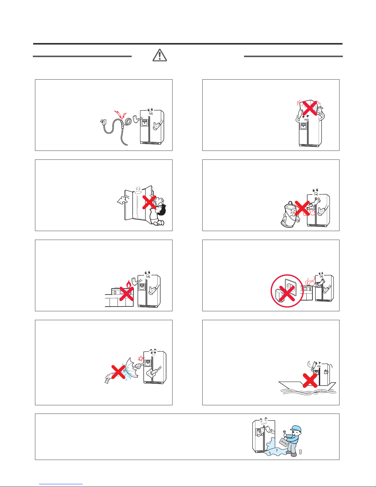
WARNING
Do not alter the power cord.
Replace it only with an exact factory
replacement part.
Electric shock or
fire may occur
due to electrical
damage of power
cables.
Do not hang or swing from the
refrigerator doors.
Do not allow children to
play with the refrigerator.
The refrigerator may turn
over. Hands and fingers
may be pinched.
Do not install the refrigerator next
to a stove or other sources of heat.
There is danger of fire.
Do not place heavy objects on the
refrigerator.
Falling objects when
opening or closing doors
may cause injury.
Do not use flammables near a
refrigerator.
There is danger of fire.
When a gas leak occurs, do not
unplug the refrigerator. Open the
doors for ventilation.
There is danger of
burning due to
explosion and
sparking.
Do not clean the refrigerator by
spraying water inside or outside.
It may result in
product damage,
fire, or electric
shock.
If the refrigerator is submerged or otherwise inundated
with water, have it checked by an authorized servicer.
Electric shock or fire may occur.
This refrigerator is designed for
use as a consumer home
appliance only.
It is not a precision
device for storing
medication or valuables.
Do not install the
refrigerator in a vehicle,
aircraft, maritime vessel,
or other than in a home
environment.
Safety Warning and Cautions
WARNING
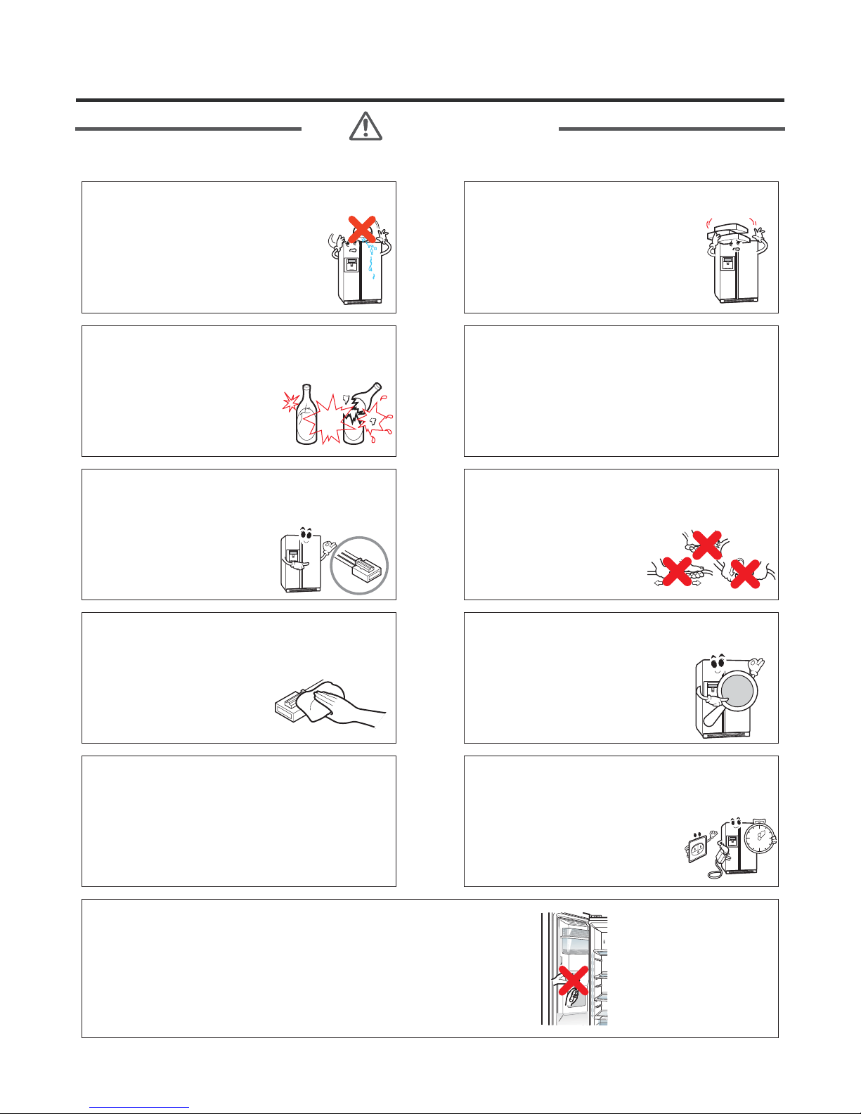
Do put the vessel that flower base,
cup, cosmetics or drugs, etc
are contained on the
refrigerator.
Fire or electric shock may occur, or
injury due to dropping may occur.
Do not put glass bottles or other
sealed containers in the freezer.
They may burst, leaving
glass fragments in the food
and possibly causing injury.
Secure the cord behind the
refrigerator.
Do not allow the cord to
hang where it can be
pinched, damaged, or rolled
over by the refrigerator.
Do not accumulate objects on a
refrigerator or do not keep
foods in random method.
Dropping of objects when opening
or closing the door may cause
physical injury.
Be sure to use rated parts for
replacement of electric parts.
Use factory replacement parts.
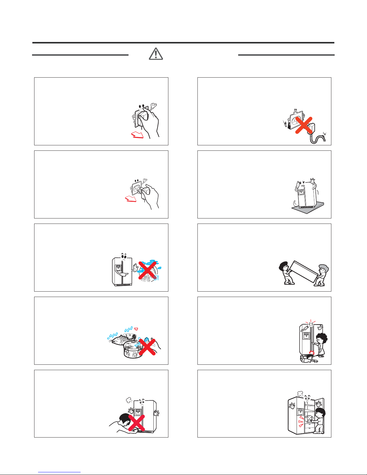
Pull the plug out by the plug body;
do not pull the wire to disconnect
the cord.
Damage to power cords
may cause fire or electric
shock.
Keep electrical parts and
connections free from dust and
contamination.
There is danger of fire
from shorting or arcing.
Do not let moisture drop onto
electrical parts.
If there is a problem in this area, replace the
parts or tape the wires to prevent
contamination and degradation.
Do not put your hands, fingers, tools, or other
objects into the icemaker, crusher, or discharge
outlet. Do not check the operation of the ice
dispenser or crusher in this manner.
You may damage your product, fingers, or tools.
Be sure replacement parts are an
exact fit.
Replacement parts should look
and fit exactly like the original
parts and have the same electric
rating.
If you unplug the refrigerator or
turn off the power, wait 5 minutes
before plugging it back in
or turning the power on.
Rapid cycling of the compressor
could cause failure.
Safety Warning and Cautions
WARNING
power plugs catching with the end
of plugs without catching cords.
Fire may occur due to electric
shock or short-circuit.
Unplug the refrigerator if it is
going to be unused for an
extended period.
Remove all food items,
wipe down the inside of
the refrigerator, dry it
thoroughly, and prop the
doors open to allow air
circulation.
Do not install the refrigerator in a
place where it is subject to
splashing and excess moisture.
Deterioration of insulation
may cause electrical
leakage.
Do not use power cords or power
plugs when they are damaged or
holes of power plugs are loose.
Fire may occur due to
electric shock or
short-circuit.
Be sure the floor will support the
weight of the refrigerator.
If the refrigerator is not installed
at a firm, level location, the
doors and icemaker may not
operate properly.
To carry the refrigerator, use the
handles at the top of the back, and
beneath the edge of the front.
Using these handles will
ensure safety and reduce
the possibility of injury.
Do not touch foods, containers, or
the inside of the freezer
compartment with wet hands.
Your hands may stick
to the cold items. It
could cause frost bite.
Do not stick your hands or fingers
under the bottom of the
refrigerator.
Watch out for sharp
edges.
Be careful to avoid pinching hands
or feet when opening the doors.
Do not put live animals in the
refrigerator.
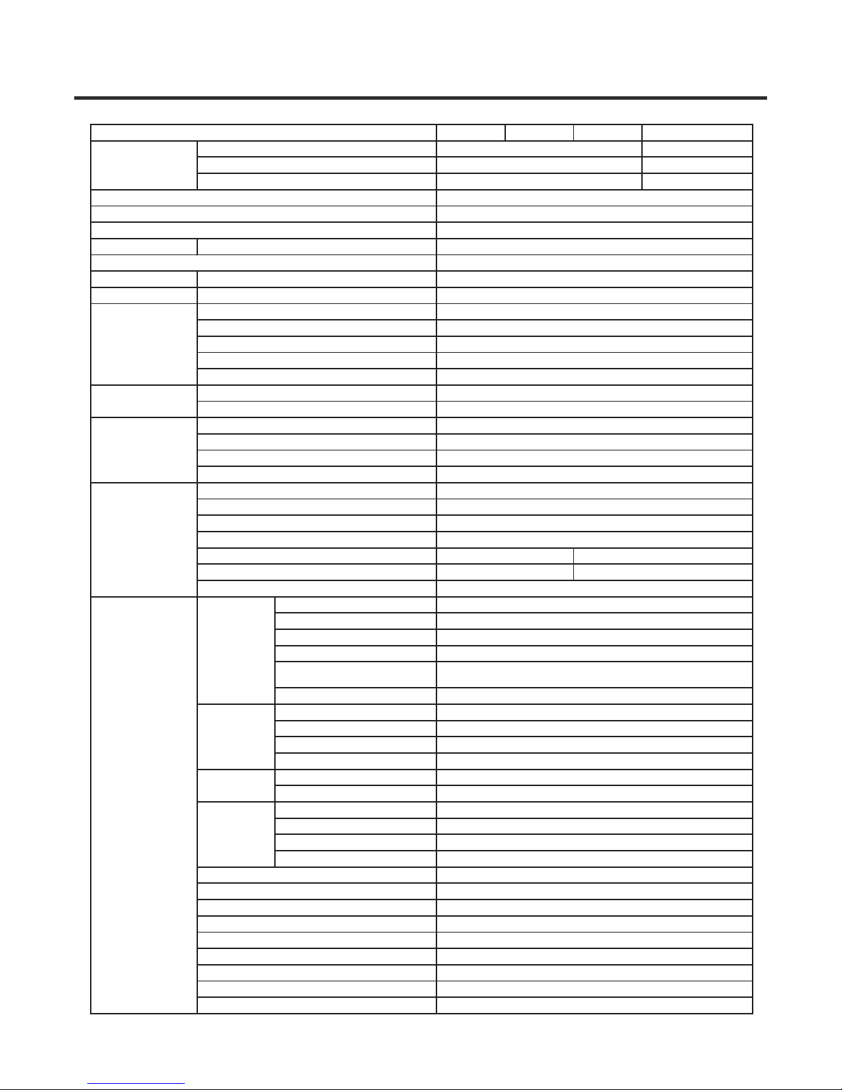
Product Standards
Effective inner
capacity
Outer dimension ( W X D X H )
Product weight (lb)
Rated consumption power of motor
Heater
Cooling method
Temperature control
Defrost
F-Room
R-Room
Freezing cycle
Electrical parts
srandard
F-Room
F-Room
F-Room
Method
Start
End
EvaPoration
Type of heat shield
Fixed Shelf
Drawer
Fixed Shelf
Shelf(Movable, Folding)
Egg container
Vegetable room
Compressor driving method
EvaPoration
Conderser
F-Room oil
Type of refrigerant
Capillary tube
Dryer (drying tube)
Parts related
with dewing
prevention
Capacitor
For
preventing
ice making
Overload protective device
F-Room fan motor
Fan motor for cooling condenser
Inside lamp at F-Room
Inside lamp at R-Room
Door switch (F-Room/R-Room)
Home bar door switch
Main Fuse
Power cord
Model
Total inner capacity(L)
F-Room
R-Room
Initial defrost
Defrost cycle
Rest time
Defrost sensor
Temp.fuse (rated/ operation
temperature)
Heater Sheath
Dispenser duct door heater
R-Room home bar heater
F-Room home bar heater
Dispenser heater
Comp’ Running
I/maker geared motor Running
Magic room Damper Heater
R-Room Damper Heater
Water Tank Heater
Water supply Heater
LSXS26466* LSXS26386* LSXS26366* LSXS26326*
738.66L (26.09 Cu.ft)
260.59L (9.20 Cu.ft)
478.07L (16.89 Cu.ft)
35 7/8" x 35 7/8" x 70 3/8"
298
105 ± 15%(W)
260 ± 10%(W)
Indirect cooling(F-Control)
MICOM(Outside)
MICOM(Outside)
Forced method
Auto
Auto
Forced method
Cyclo-Pentane
3
2
4
-
-
2
A Logic Inverter operation
Pin tube type
Forced convection method
Freol Alpha5 oil(175cc)
R134a(165g)
Φ 0.7/0.9
MOLECULAR SIEVE XH-9
4~5 hours (vary depending on condition)
9~11 hours (vary depending on condition)
3 Min
Returend to defrost function when reaching to 5℃
250V / 72℃
AC 115V / 260W
-
120V / 6.5W
-
DC 12V / 2.5W
AC 450V / 20 ㎌
AC 250V / 14 ㎌
-
DC 12V / 1W
-
DC 12V / 0.8W
MRA12325
DC 13V
DC 13V
DC 12V / 5W (1EA)
DC 12V / 5W (1EA)
250 V / 0.5 A
250 V / 0.5 A
250 V / 10 A
AC 125 V / 10 A
742.49L (26.22 Cu.ft)
260.59L (9.20 Cu.ft)
481.90L (17.02 Cu.ft)
R134a(175g)
Φ 0.75
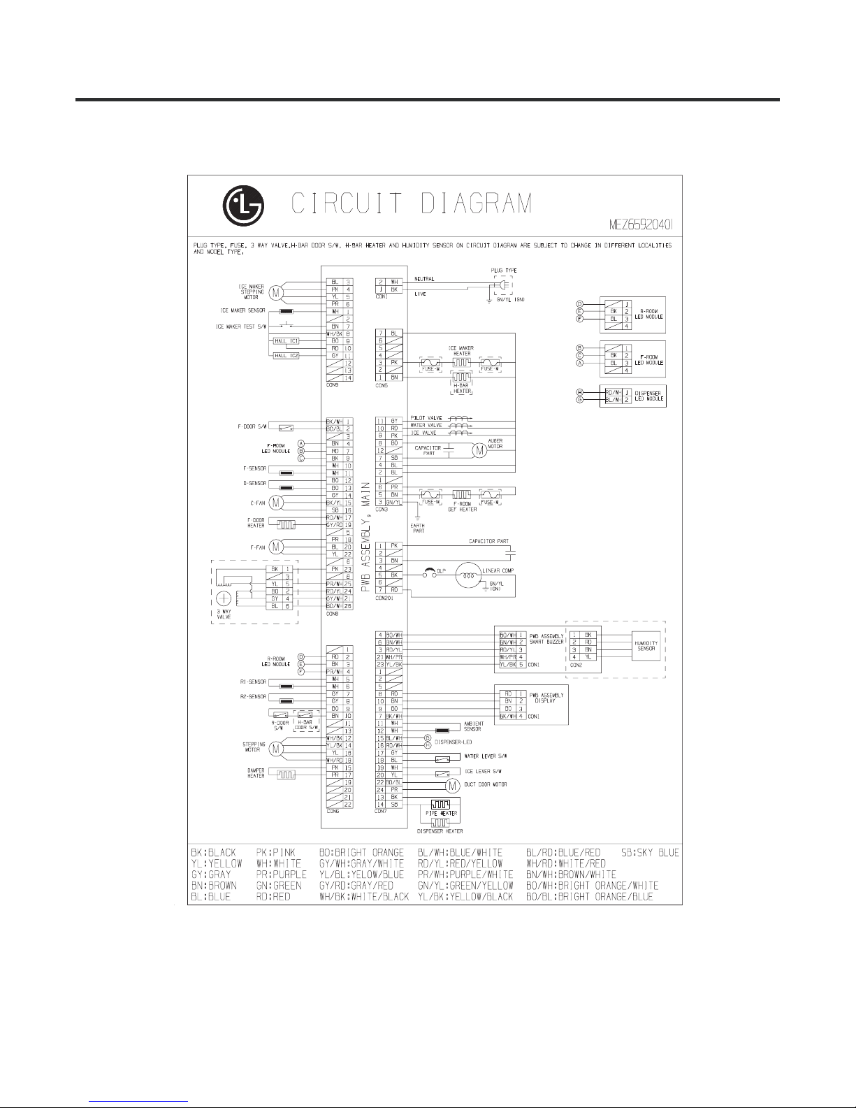
Circuit Diagram
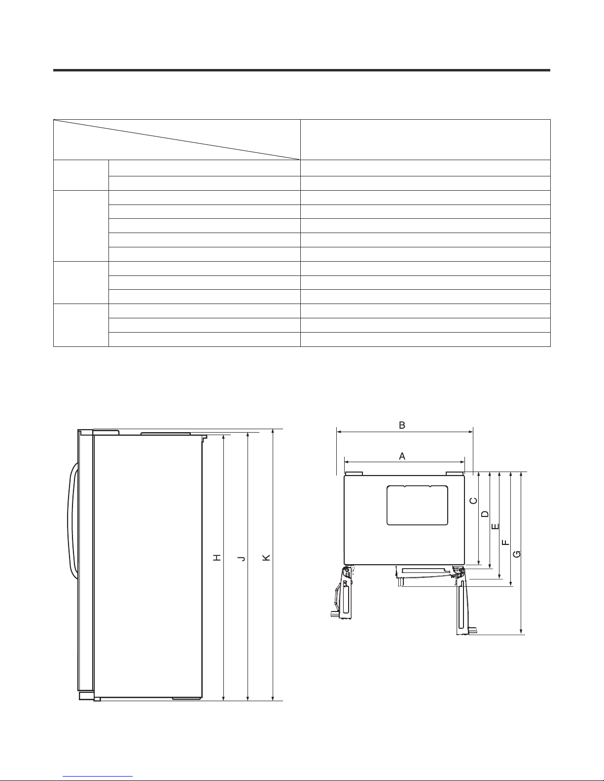
Specifications
1. Specifications
Unit : inch (mm)
ltem
Width
Depth
Height
Minimum air
circulation
space
Model
Width (A)
When opening door by 90° (including handle) (B)
Case (including back handle) (C)
After disassembling door (including hinge, L) (D)
Including door (not including handle) (E)
Including handle (F)
When opening door by 90° (G)
Cabinet (H)
Including cover PWB (J)
Including door (K)
Top part
Side
Rear part
LSXS26466 LSXS26386
LSXS26366 LSXS26326
*/ *
* / *
35.9 (912)
39.6 (1005)
28 7 730.( )
31 5 800.( )
33 4 848.( )
35 9 912.( )
50 6 1285.( )
68 9 1750
69 3 1760.( )
70.3 (1785)
11.8 (300)
0.8 (20)
2.0 (50)
Front View
Top View
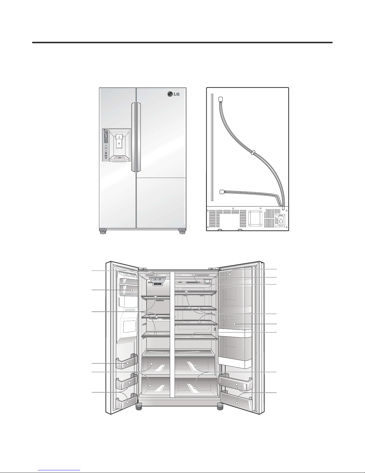
Appearance Size of Refrigerator and Name of Every Part
2. Main Name
MODEL : LSXS26466 LSXS26386 LSXS26366*/ */ *
LED Lamp
Automatic
Icemaker
Shelf
Door Bin
Freezing Zone
Door Bin
Freezer
Compartment
Refrigerator
Compartment
Dairy Corner
Filter
LED Lamp
Shelf
Refreshment center
Shelf
Fresh zone
Door Bin
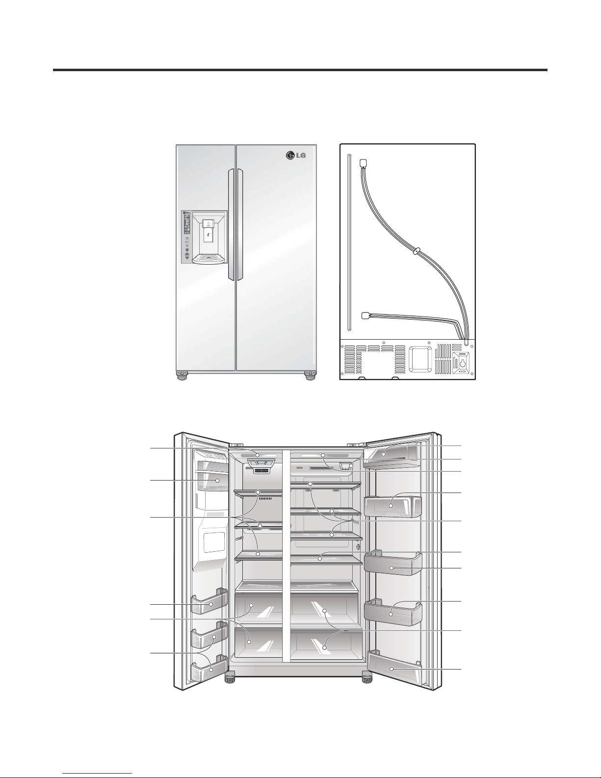
Appearance Size of Refrigerator and Name of Every Part
2. Main Name
MODEL : LSXS26326*
LED Lamp
Automatic
Icemaker
Shelf
Door Bin
Freezing Zone
Door Bin
Freezer
Compartment
Refrigerator
Compartment
Dairy Corner
Filter
LED Lamp
Door Bin
Shelf
Shelf
Door Bin
Door Bin
Fresh zone
Door Bin
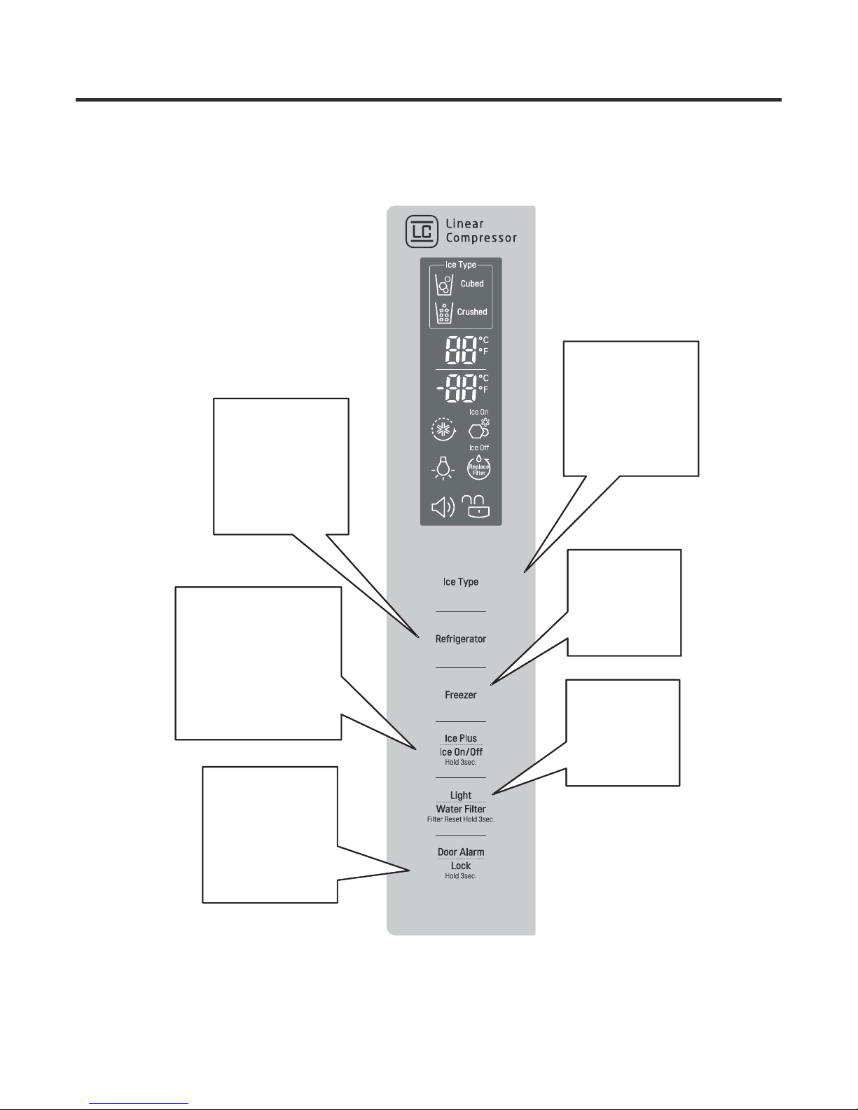
Micom Function
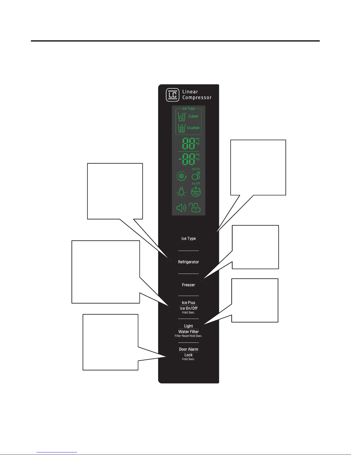
1. Operating Panel
MODEL : LSXS26466*
Ice Type
Refrigerator
Temperature
adjustment button
for refrigerator
compartment
Ice Plus
Ice on / off
Ice Plus
button(1sec)
Ice Making ON
OFF 3secs button
() )
/
Door Alarm
Dispenser
Selection Button
Freezer
Temperature
adjustment button
for freezer
compartment
Light /
Water Filter
Dispenser light
on/off button &
filter reset
button(3secs)
Door Alarm
Lock / Unlock
button(3secs)
Micom Function
1. Operating Panel
MODEL : LSXS26386 LSXS26366 LSXS26326** /*
Ice Type
Refrigerator
Temperature
adjustment button
for refrigerator
compartment
Ice Plus
Ice on / off
Ice Plus
button(1sec)
Ice Making ON
OFF 3secs button
() )
/
Door Alarm
Dispenser
Selection Button
Freezer
Temperature
adjustment button
for freezer
compartment
Light /
Water Filter
Dispenser light
on/off button &
filter reset
button(3secs)
Door Alarm
Lock / Unlock
button(3secs)
Micom Function
2. Function description
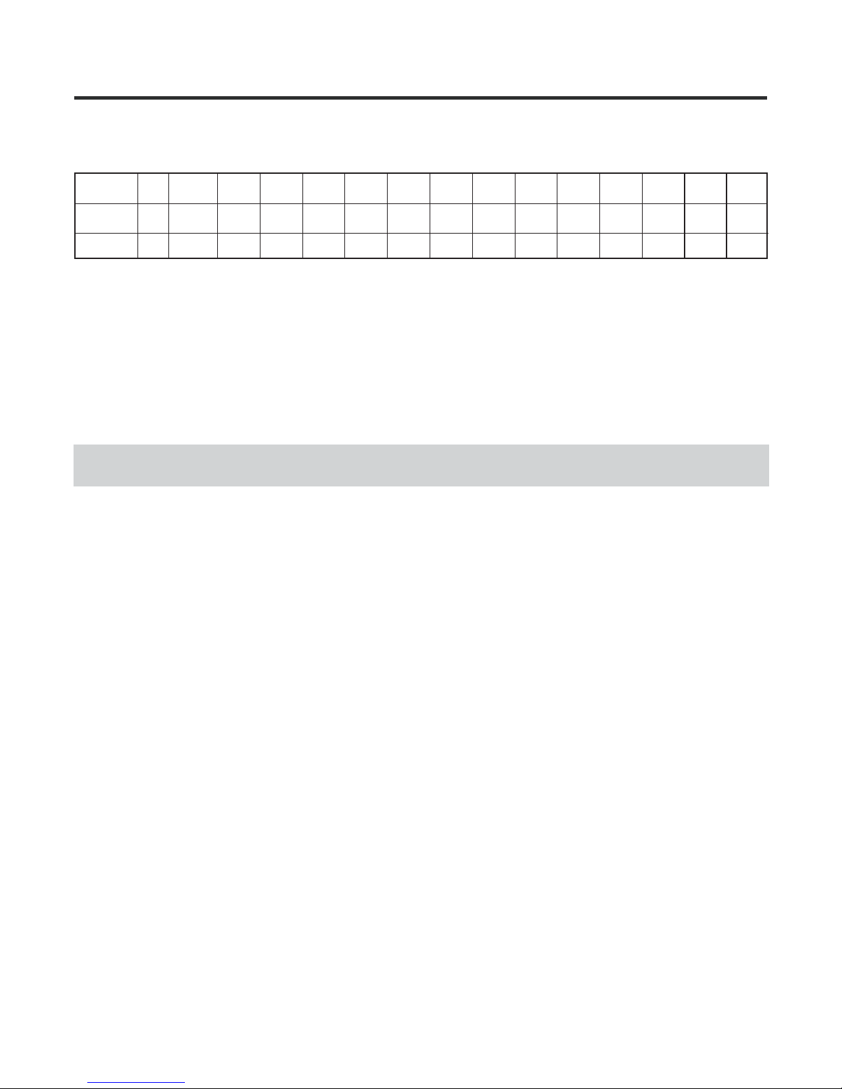
2-1. Funnction of Temperature Selection
Notch
Freezer -10 -2-3-4-6865432
Refrigeration 3637 35 34 33 46 45 44 43 42 41 40
Te mp
°F
°F
Power
Initiallly On
1st press
2nd press 3rd press 4th press 5th press 6th press 7th press 8th press 9th press
10th press 11th press
12th press
39
13th press
1
0
38
1. The actual inner temperature varies depending on the food status, as the indicated setting temperature is a target
temperature, not actual temperature within refrigerator.
2. Refrigeration function is weak in the initial time. Please adjust temperature as above after using refrigerator for minimum
2~3 days.
2-2. Automatic ice maker
The automatic icemaker can automatically makes 120~ 220 cubes per day. This quantity may vary by usage condition, including
ambient temperature, door opening, freezerload,and etc.
Icemaker stops making ice whentheice storage bin is full.
If you don’t want to have the automatic icemaker make ices, press and hold ICE ON/OFF button until the indicator lights on. If you
want to have icemaker makesicesagain, press and hold ICE ON/OFF button untiltheindicator lights off.
While ICE OFF indicator is on, Icemaker stops making ice. But you can dispense the ices until the ices run out from the ice
storage.Micom Function
2-3. When ice is not dispensedsmoothly
Ice is lumped together
• When ice is lumped together, take the ice lumps out of the ice storage bin, break them into small pieces, and then place them into
the ice storage bin again.
•
When the ice dispenser produces too small or lumped together ice, the amount of water supplied to the ice dispenser need to be
adjusted. Contact the service center.
• If ice is notusedfrequently, it maylump together.
Power failure
Ice may drop into the freezer compartment. Take the ice storage bin out and discardall the ice then dry it and place it back.After the
machine is powered again, thepreviousselection mode remains.
The unit is newly installed
It takes about 12 hoursfora newly installed refrigerator to make ice inthefreezer compartment.
2-4. Ice Plus
1. Ice Plus is function to improve cooling speed of the freezing room by consecutively operating compressors and freezing room
fan.
2. Ice Plus is releasedifpower failure occurs and then returns to theoriginalstatus.
3. Temperature setting isnot changed even if selecting the Ice Plus.
4. The change of temperature settingatthe freezing room or the cold storage roomisallowed with Ice Plus selected and processed.
5. The cold storage room operatesthestatus currently set with Ice Plus selected andprocessed.
6. If selecting the IcePlus,the Ice Plus function is released after continuouslyoperatingcompressor and freezing room fan.
7. If frost removal starting time is arrived during Ice Plus, Ice Plus operation is done only for the remaining time after completion of
frost removal when theIce Plus operation time passes 90minutes. If passing 90 minutes, IcePlus operation is done only for2 hours
after completion of frost removal.
8. If pressing Ice Plus button during frost removal, the Ice Plus LED is turned on but if pressing the Ice Plus, compressor operates
after the remaining time haspassed.
9. If selection Ice Plus within 7 minutes (delay for 7 minutes of compressor) after the compressor stops, compressor operates after
the remaining time has passed.
10. The freezing room fan motoroperatesat the high speed of RPM during operationofIce Plus.
11. During 21 hours after Pill Down Operation, F-Room is controlled at Maximum F-Notch normally and F-Fan operates normal
RPM.
12. The light of Ice Pluswouldbe turned off after Ice Plus.
13. Execute defrost immediately in case of defrost signal occurs in Ice Plus and defrosting time is included at execution time 21
hours.
14. If Ice Plus isstartedduring 2nd Load response operation, 2nd Load responseoperationwill be canceled.
15. If the button of Ice Plus in display is turned off, Ice Plus operation will be canceled. The compulsory operation of F notch in the
water tank’s preventing frost is priortothe one of Ice Plus.
Micom Function
2-5. Control of variable type of freezing room fan
1. To increase cooling speed and load response speed, MICOM variably controls freezing room fan motor at the high speed of
RPM and standard RPM.
2. MICOM only operates in the input of initial power or special freezing operation or load response operation for the high
speed of RPM and operates in the standard RPM in other general operation.
3. If opening doors of freezing / cold storage room or home bar while fan motor in the freezing room operates, the freezing
room fan motor normally operates (If being operated in the high speed of RPM, it converts operation to the standard RPM).
However, if opening doors of freezing room, the freezing room fan motor stops.
4. As for monitoring of BLDC fan motor error in the freezing room, MICOM immediately stops the fan motor by determining that
the BLDC fan motor is locked or poor if there would be position signal for more than 65 seconds at the BLDC motor.
Then it displays failure (refer to failure diagnosis function table) at the display part of refrigerator, performs re-operation in the
cycle of 30 minutes. If normal operation is performed, poor status is released and refrigerator returns to the initial status
(reset).
2-6. Control of M/C room fan motor
1. The M/C room fan motor performs ON/OFF control by linking with the COMP.
2. It controls at the single RPM without varying RPM.
3. Failure sensing method is same with freezing fan motor.(refer to failure diagnosis function table for failure display).
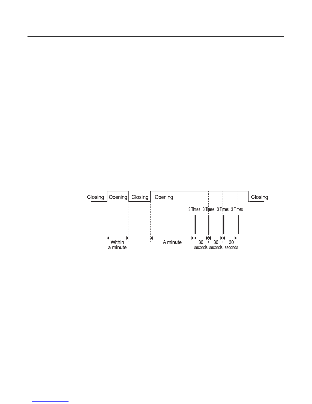
2-7. Door opening alarm
1. Buzzer generates alarm sound if doors are not closed even when more than a minute consecutively has passed with doors
of freezing / cold storage room or home bar opened.
2. Buzzer rings three times in the interval of 0.5 second after the first one-minute has passed after doors are opened and then
repeats three times of On/Off alarm in the cycle of every 30 seconds.
3. If all the doors of freezing / cold storage room or home bar are closed during door open alarm, alarm is immediately
released.
Doors of freezing /
cold storage room
or home bar
BUZZER
2-8 Ringing of button selection buzzer
1. If pressing the front display button, “Ding ~ “ sound rings.
2-9. Ringing of compulsory operation, compulsory frost removal buzzer
1. If pressing the test button in the main PCB, “Phi ~ “ sound rings.
2. In selecting compulsory operation, alarm sound is repeated and completed in the cycle of On for 0.2 second and Off for 1.8
second three times.
3. In selecting compulsory frost removal, alarm sound is repeated and completed in the cycle of On for 0.2 second , Off for 0.2
second, On for 0.2 second and Off for 1.4 second three times.
Micom Function
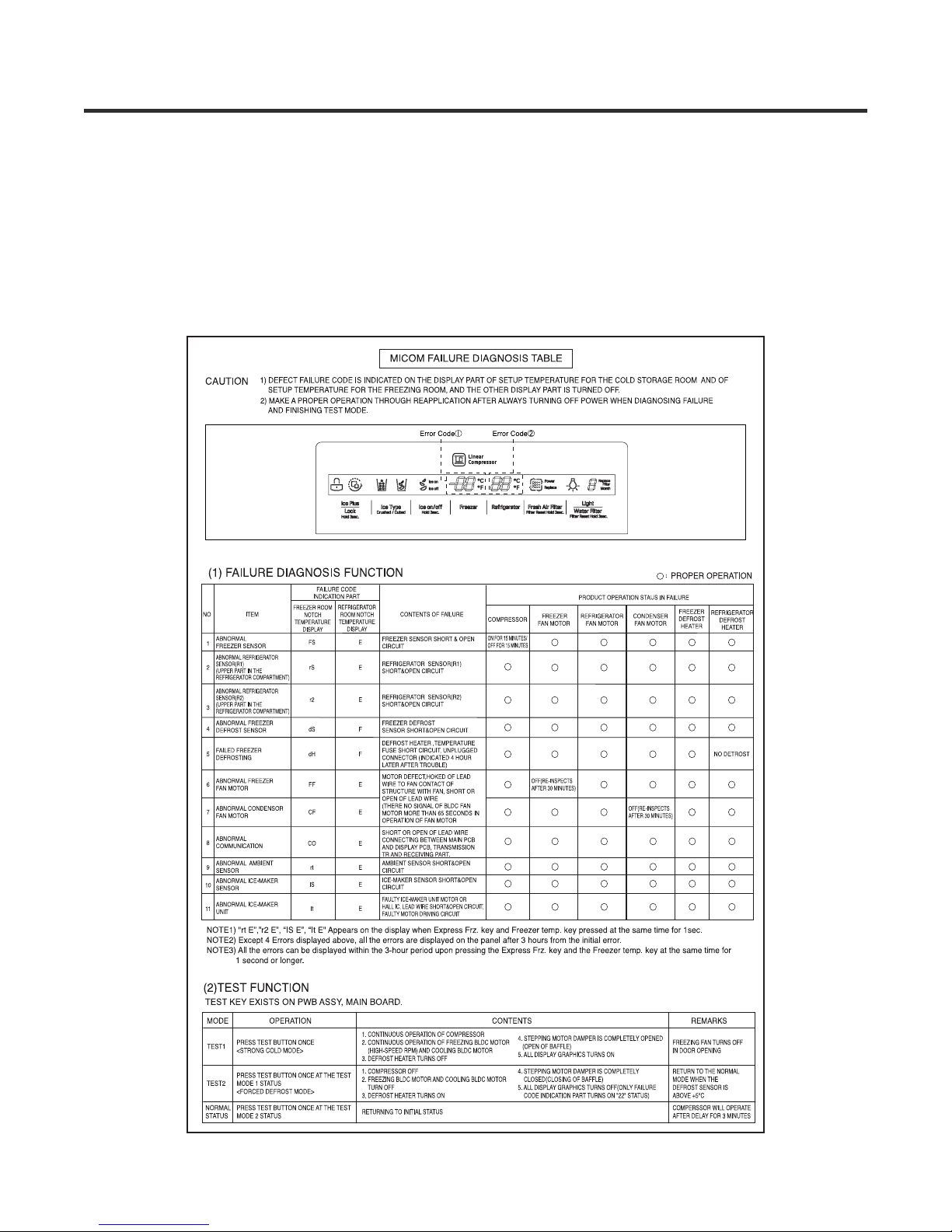
2-10. Function of Trouble Diagnosis(88-LED)
1. Failure diagnosis function is function to facilitate service when nonconforming matters affecting performance of product
during use of product.
2. In occurrence of failure, pressing the function adjustment button does not perform function and only alarm sound (“Ding~”)
rings.
3. If nonconforming matters occurred are released during display of failure code, MICOM returns to the original state (Reset).
4. Failure code is displayed on the display part of setting temperature for the freezing room and the display part of setting
temperature for the cold storage room of LED, which are placed at the display part of a refrigerator. All the LED graphics other
than a failure code are turned off
Micom Function
2-11. Test Function
1. Test function is function to find out any failed part in the failure status or check function of PWB and the product.
2. The test button is placed on the main PCB (test switch) of the refrigerator. The refrigerator ends the test mode after Max.
2 hours irrespective of modes and returns to normal status (reset).
3. The function control button is not detected during test mode.
4. When ending test mode, take out power cords and insert them again so as to become normal status.
5. If defect such as sensor failure during test mode is detected, release Test Mode to display failure code.
6. Test Mode is not performed even if pressing the test button during display of failure code.
MODE OPERATION CONTENTS REMARKS
TEST1
TEST2
NORMAL
STATUS
PRESS THEST
BUTTON ONCE
<STRONG COLD
MODE>
PRESS TEST
BUTTON ONCE AT
THE TEST MODE 1
STATUS
<FORCED DEFROST
MODE>
PRESS TEST
BUTTON ONCE AT
THE TEST MODE 2
STATUS
1.CONTINUOUS OPERATION OF COMPRESSOR
2.CONTINUOUS OPERATION OF FREEZING
BLDC MOTOR (HIGH-SPEED RPM) AND
COOLING BLDC MOTOR
3.DEFROST HEATER TURNS OFF
1.COMPRESSOR OFF
2.FREEZING BLDC MOTOR AND COOLING BLDC
MOTOR TURN OFF
3.DEFROST HEATER TURNS ON
RETRUING TO INITIAL STATUS COMPERSSOR WILL OPERATE
4.STEPPING MOTOR DAMPER IS
COMPLETELY OPENED
(OPEN OF BAFFLE)
5.ALL DISPLAY GRAPHICS TURNS ON
4.STEPPING MOTOR DAMPER IS
COMPLETELY CLOSED(CLOSING OF
BAFFLE)
5.ALL DISPLAY GRAPHICS TURNS
OFF(ONLY FAILURE CODE INDICATION
PART TURNS ON “22”STATUS)
FREEZING FAN TURNS OFF IN DOOR
OPENING.
RETURNS TO THE NORMAL MODE
WHEN THE DEFROST SENSOR IS
ABOVE +5°C
AFTER DELAY FOR 3 MINUTES
2-12. Functions performed when Ice Dispenser and Water Dispenser are mounted
1. This is function to dispense ice and water outside without opening doors.
2. If pressing the Dispenser Pressing Switch after selecting ice (cube ice, Crushed ice) or water, relevant ice and water come
out. However, when selecting ice, the duct door is opened by electric Motor (duct door, Motor) if pressing the Dispenser
Pressing Switch. The duct door is closed after it remains for 5 seconds in open status if pressing and then releasing the
Dispenser Pressing Switch.
3. Function to dispense ice and water out stops in the F-door open status.
4. If there is no OFF signal for 3 minutes after pressing the Dispenser Pressing Switch after selecting ice (cube ice, crushed
ice) or water, the refrigerator automatically turns off both gear motor and solenoid (cube, water).
However, the Motor (duct door) stops when 5 seconds pass after turning off. (This is for preventing coil-short due to heating of
solenoid.)
5. Dispenser Lamp On/Off Function
If pressing the Dispenser Pressing Switch after selecting ice (cube ice, crushed ice) or water, the lamp on the dispenser part
turns on and if releasing it, turns off.
6. Crushed Ice/Cube Select Function
1) This is function to operate the refrigerator as Crushed Ice/Cube function on the function control part depending on user s
selection. If pressing the Select Dispenser button, display and selection are done.
2) For the initial Power On, Crushed ice is automatically selected.
3) If pressing the Press Switch when ices are generated in the ice bank for selecting Crushed Ice, the refrigerator operates the
gear motor so that crushed ices are supplied outside.
4) If pressing the Press Switch when ices are generated in the ice bank for selecting Cube Ice, the refrigerator operates the
gear motor so that Cube ices are supplied outside.
Micom Function
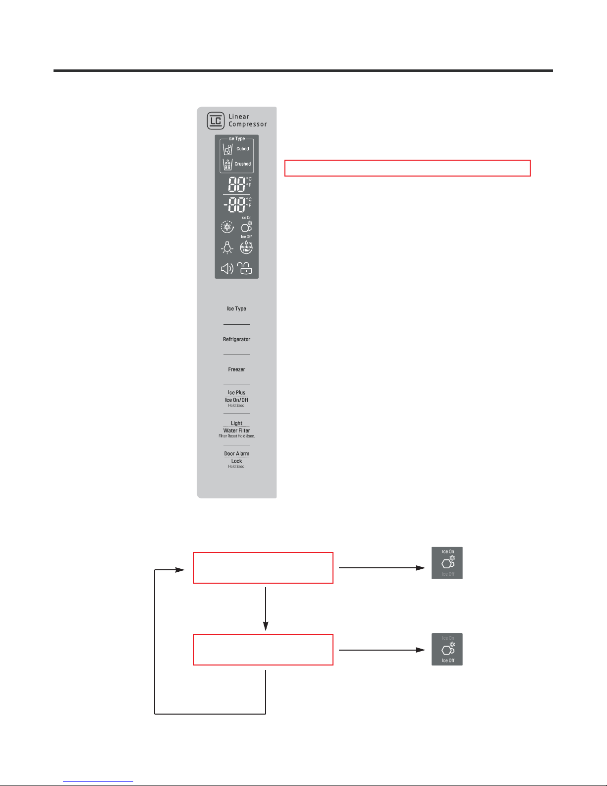
2-13 Ice on / off function
Press Ice on/off Button to select Ice Making on or off.
Ice on Mode in factory default setting.
Ice on
Ice on / off BUTTON
Ice off
Ice on / off BUTTON
Icemaker and dispenser working principles and repair
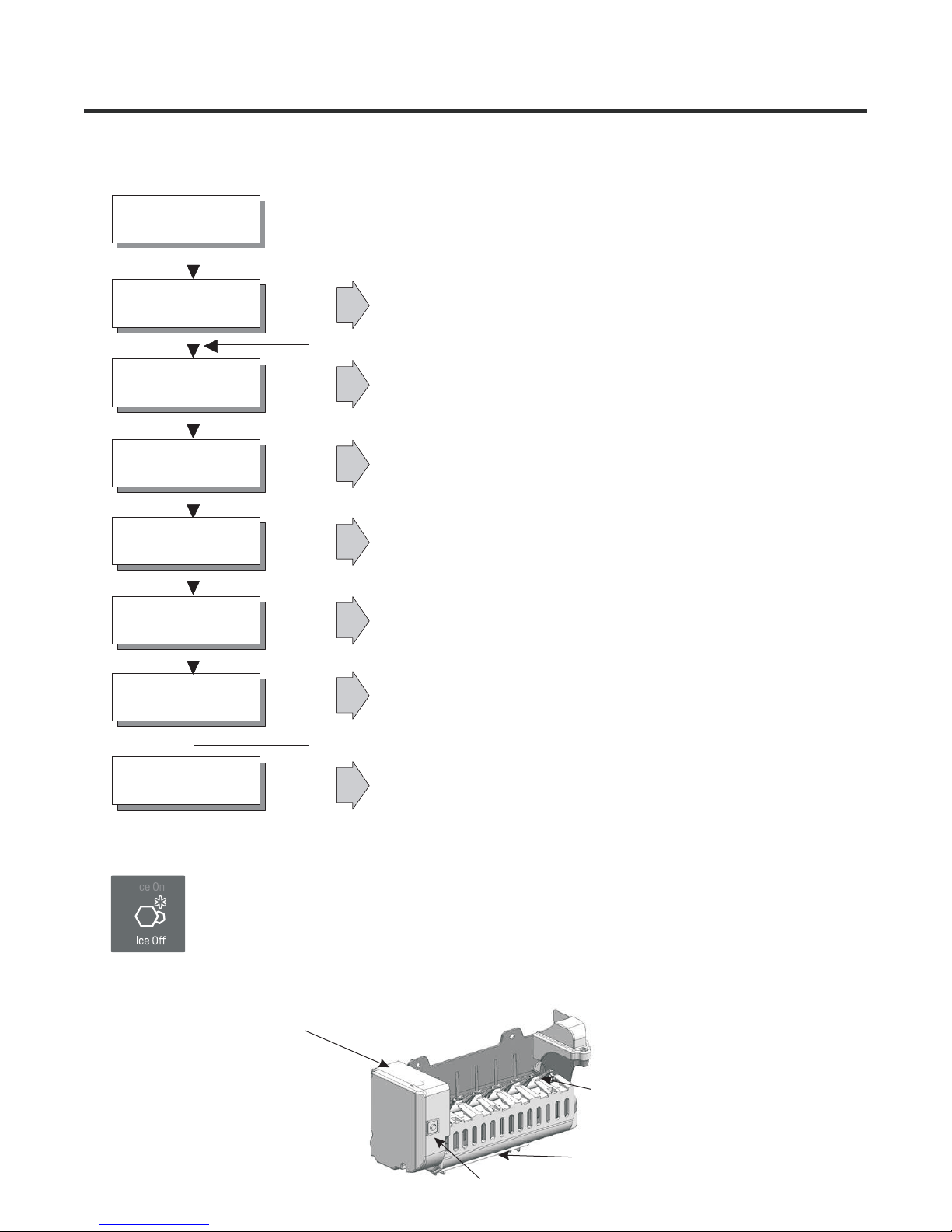
1. OPERATION PRINCIPLE
1-1. Operation Principle of Icemaker
Power On
Start Position
Icemaking
Mode
Checking full
ice Mode
Harvest
Mode
Fill Water
Park Position
• Adjusts EJECTOR to
Waits until water becomes cold after starting the
•
Start Position with power on.
icemaking operation.
• Check if the ice bin is full.
• Runs MOTOR to drop ice from the tray into the ICE
BIN.
• Performs after supplying water by
Ice Making Mode
operating the SOLENOID in ICE VALVE.
With the detect lever, checks if the ICE BIN is full.
•
Test Mode
• ICE-MAKING STATUS INDICATOR Shows Ice-making status. While the indicator lights on, Icemaker
stops making ice.
• Press and hold the ICE ON/OFF button on display for 3sec. to stop or restart making ice.
While ICE OFF indicator is on, Icemaker stops making ice. But you can dispense the ices until the ices run out from the ice
storage.
Icemaker
• To operate LINE and SERVICE, press and hold the
Test Button
for 3 seconds. The icemaker will run through 3 stages:
Harvest Fill Icemaking.→→
EJECTOR
Feeler Arm
Test Button

Icemaker and dispenser working principles and repair
2. Function TEST
1. Before you carry out the test mode, check whether the water is frozen in the icemaker completely. If the test is
CAUTION!
performed while the water is not frozen in the icemaker, The water may overflow after test and it will cause other serious
problem.
2. This is a forced operation for TEST, Service, cleaning, etc. It is operated by pressing and holding the Test Button for 3
seconds.
3. The test works only in the Icemaking Mode. (This test works when the ejector and stainless lever is at the their original
position.)It cannot be entered from the Harvest or Fill mode.
4. After water is supplied, the mormally CYCLE is followed : Icemaking Checking full ice Harvest Fill Water
Park Position
→→→→
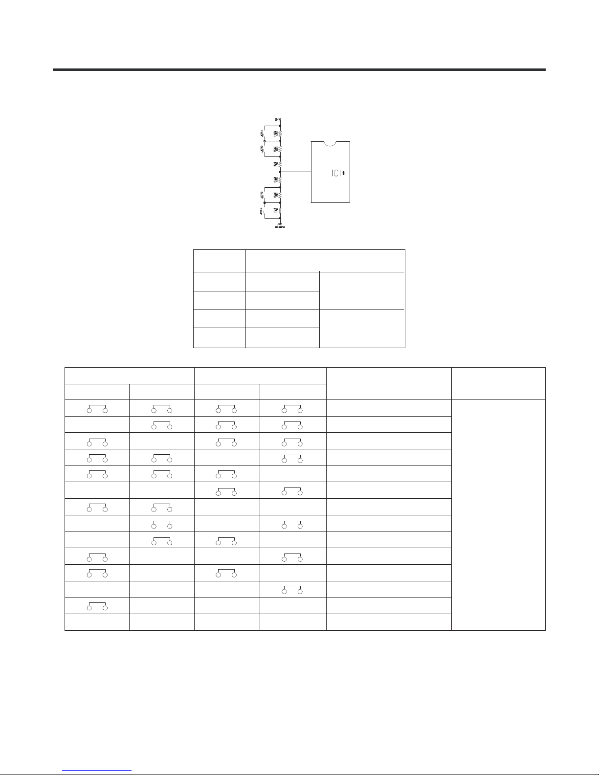
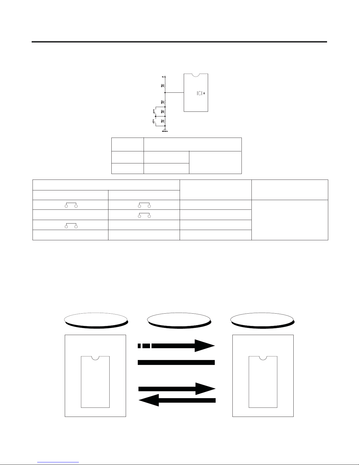
Micom Circuit description
1. Refrigerator undercool/overcool compensation circuit
Temperature compensation from cut
JCR1
JCR2
JCR3
JCR4
Undercool compensation
JCR3 JCR4
CUT
CUT
CUT CUT
CUT CUT
CUT CUT
CUT
CUT CUT
CUT CUT
CUT CUT
CUT
CUT
Overcool compensation
JCR1 JCR2
CUT
CUT
CUT
CUT
CUT
+1
+1
-1
-1
CUT
CUT
CUT
CUT
+2
-2
Refrigerator temperature
compensation
0 (Factory default)
-1
-1
+1
+1
-2
+2
0
0
0
0
-1
+1
0
Remarks
Above option circuit compensates the refrigerator temperature by simply cutting the circuit during the service.
Micom Circuit description
2. Freezer undercool compensation circuit
Temperature compensation from cut
JCF 3
JCF 4
Undercool compensa tion
JCF3 JCF4
CUT
CUT
CUT
►Above option circuit compensates the freezer temperature by simply cutting the circuit during the service.
CUT
-1
-1
-2
Freezer temperature
compensa tion
0(Factorydefault)
-1
-1
-2
Remarks
2-1. Communication circuit and connecting L/wire between main PCB and display PCB
As the communication circuit, the following circuit exchanges information required between main MICOM of main PCB and
MICOM exclusively for LED for LED control of display PCB.
Sending/Receiving L/wire is required with DC12V required to operate the display PCB.
Communication error occurs when the information exchange between main MICOM of main PCB and MICOM exclusively
for LED for LED control of display PCB is disconnected for more than 30 seconds
Main PCB Display PCB
L/Wire FD/H(4wires)
Main MICOM
DC 12V
MICOM exclusively
for LCD
GND
Send (Error condition)
Receive (NO TCH condition)
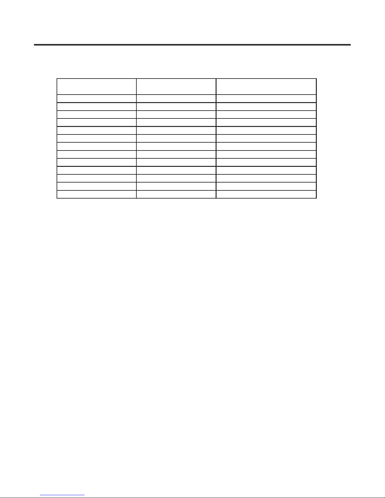
Micom Circuit description
3. Table of sensor resistance characteristics
Measured temperature Freezer sensor
-20 22.3kΩ 77kΩ
-15 16.9kΩ 60kΩ
-10 13kΩ 47.3kΩ
-5 10.1kΩ 38.4kΩ
0 7.8kΩ 30kΩ
+5 6.2kΩ 24.1kΩ
+10 4.9kΩ 19.5kΩ
+15 3.9kΩ 15.9kΩ
+20 3.1kΩ 13kΩ
+25 2.5kΩ 11kΩ
+30 2kΩ 8.9kΩ
+40 1.4kΩ 6.2kΩ
+50 0.8kΩ 4.3kΩ
Refrigerator sensor 1, 2, defrost
sensor, external sensor
 Loading...