How it Works
Log In / Sign Up
Buy Points
How it Works
FAQ
Contact Us
Questions and Suggestions
Users
LG
Loading...
L
LSUK50C12
LSUK50H12
LSUK70C12
LSUK70H12
LSUP1120AM
LSUQ076BEL
LSUR1262QCAEXPORT
LSUR126ABL
LSUS1862QC7
LSUS50D56
LSUT1862PC
LSUT1862QC
LSUT1862QCABTRFLY
LSUT1862QCAEXPORT
LSUT186ABL
2
LSUT246QEG
LSUT32D1P
LSUT32D2C
LSUT32H11
LSUT35C11
LSUT35D1A
LSUT35H11
LSUT35H12
LSUY25C11
LSUY25C12
LSUY25D1A
LSUY25H11
LSUY25H11D
LSUY25H12
LSUY32H12
LSV-700W1
3
LSV-701W1
3
LSVC302ST
2
LSVC362ST
5
LSVFSD-LP
LSW100B
4
LSW100BG
10
LSW130B
4
LSW140B
4
LSW200B
5
LSW200BG
9
LSW200BX
2
LSW200BXG
3
LSW2010F
2
LSW2010 Series
LSW220BX
5
LSW2260BCG
LSW230B
4
LSW240
LSW240B
5
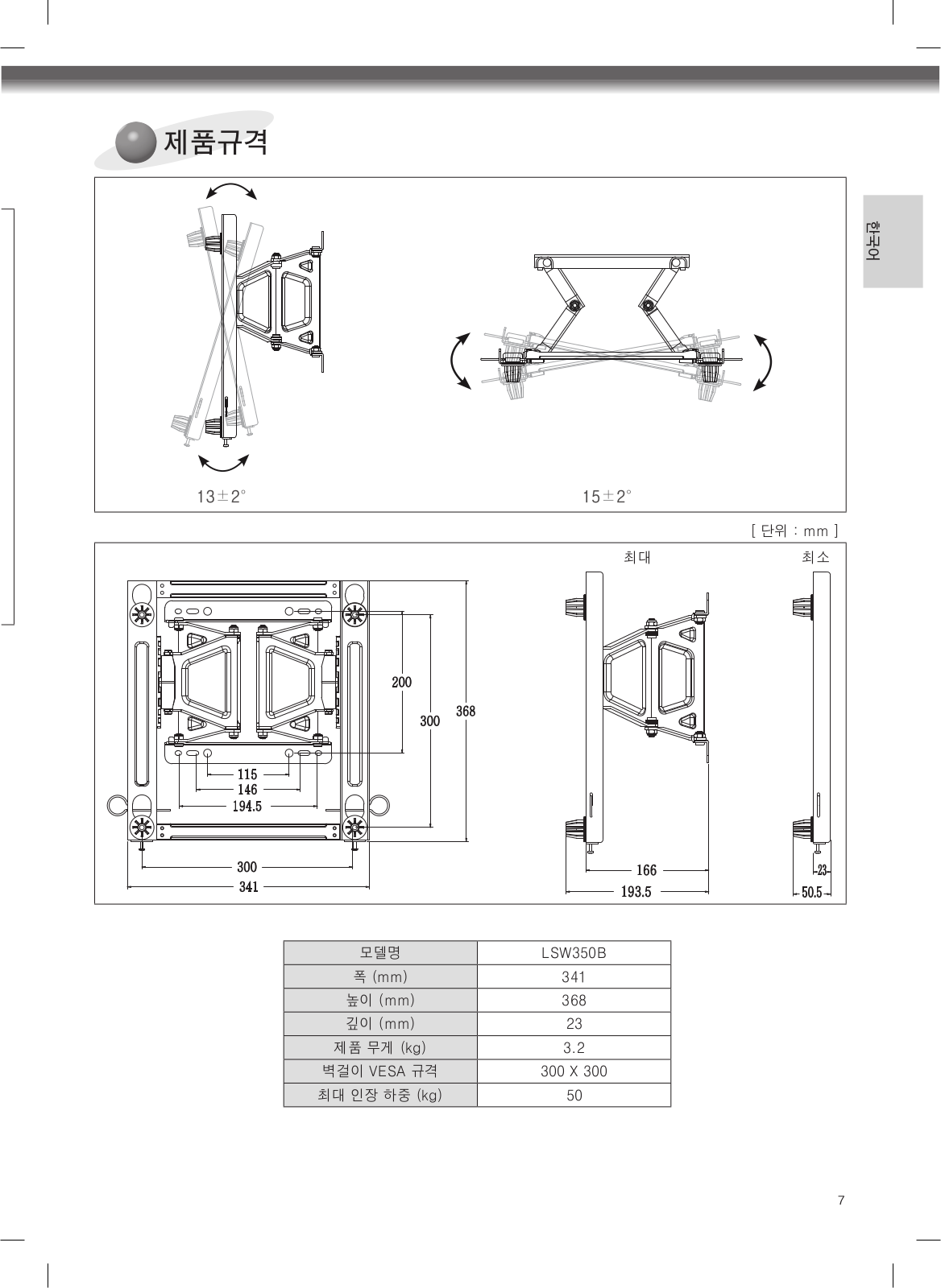
LSW350B
5
LSW400B
5
LSW400BG
7
LSW400BX
LSW400BXG
LSW420BX
4
LSW430B
4
LSW440
LSW440B
4
LSW600B
6
LSW630B
6
LSW640B
5
LSW840B
LSW900
LSW901
2
LSW901P-B
LSW901 Series
LSWC307
LSWC307ST
2
LSWD100
12
LSWD100W
LSWD300BD
3
LSWD3034ST
LSWD305ST
10
LSWD306ST
4
LSWD306ST/00
2
LSWD307ST
3
LSWD309BD
2
LSWD309BD/00
2
LSWF3885HVS
LSWF388HVS
3
LSWS300BD
3
LSWS3034ST
LSWS305ST
11
LSWS306ST
6
LSWS307ST
6
LSWS309BD
3
LSWS309BD/00
2
LSX300-4DM
3
LSX701P-B
LSXC22326
2
LSXC22336
2
LSXC22386
2
LSXC22386D
LSXC22386S
LSXC22396
LSXC22396D
2
LSXC22396D/00
LSXC22396S
5
LSXC22396 Series
Loading...
Loading...
Nothing found
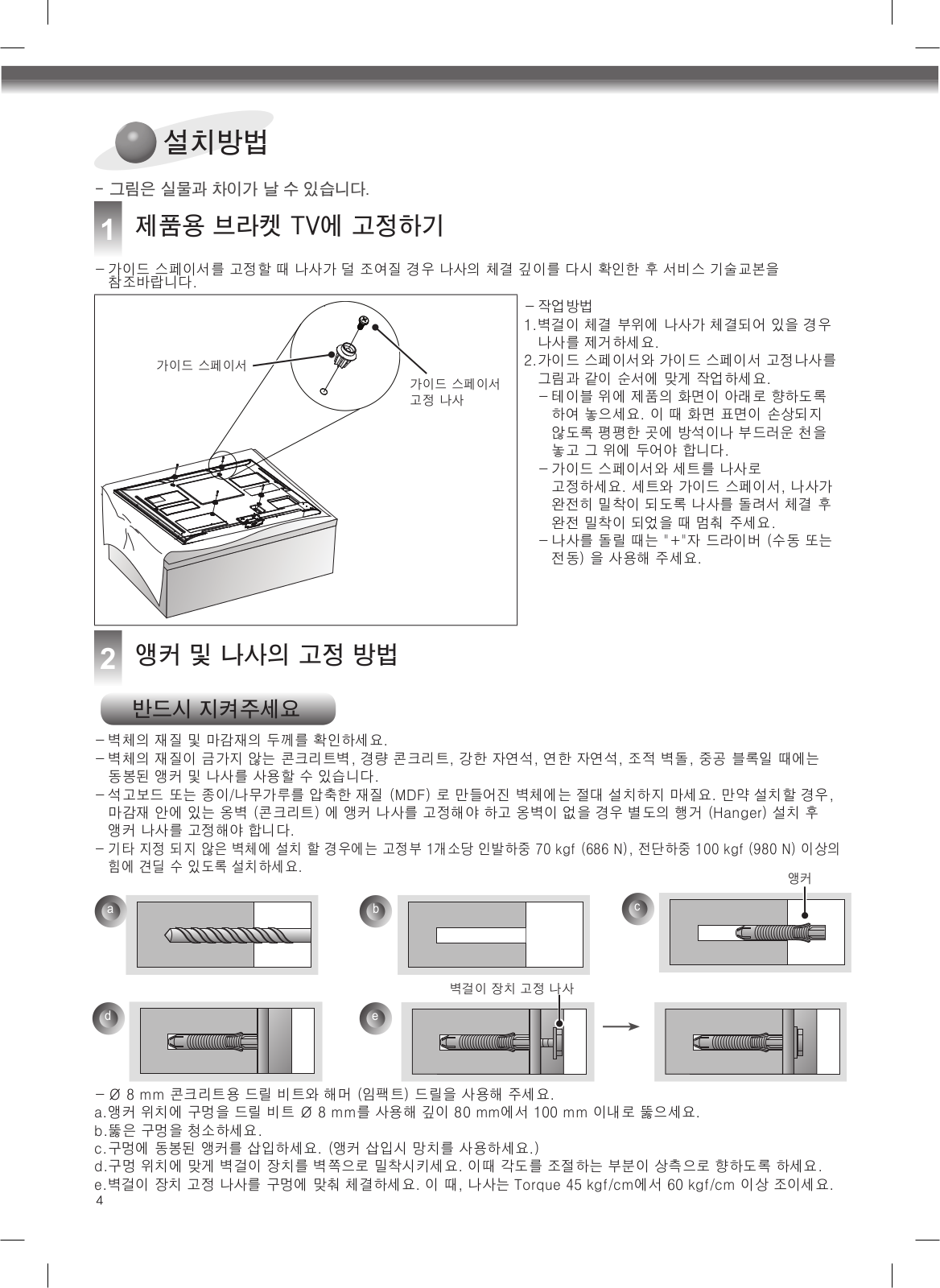
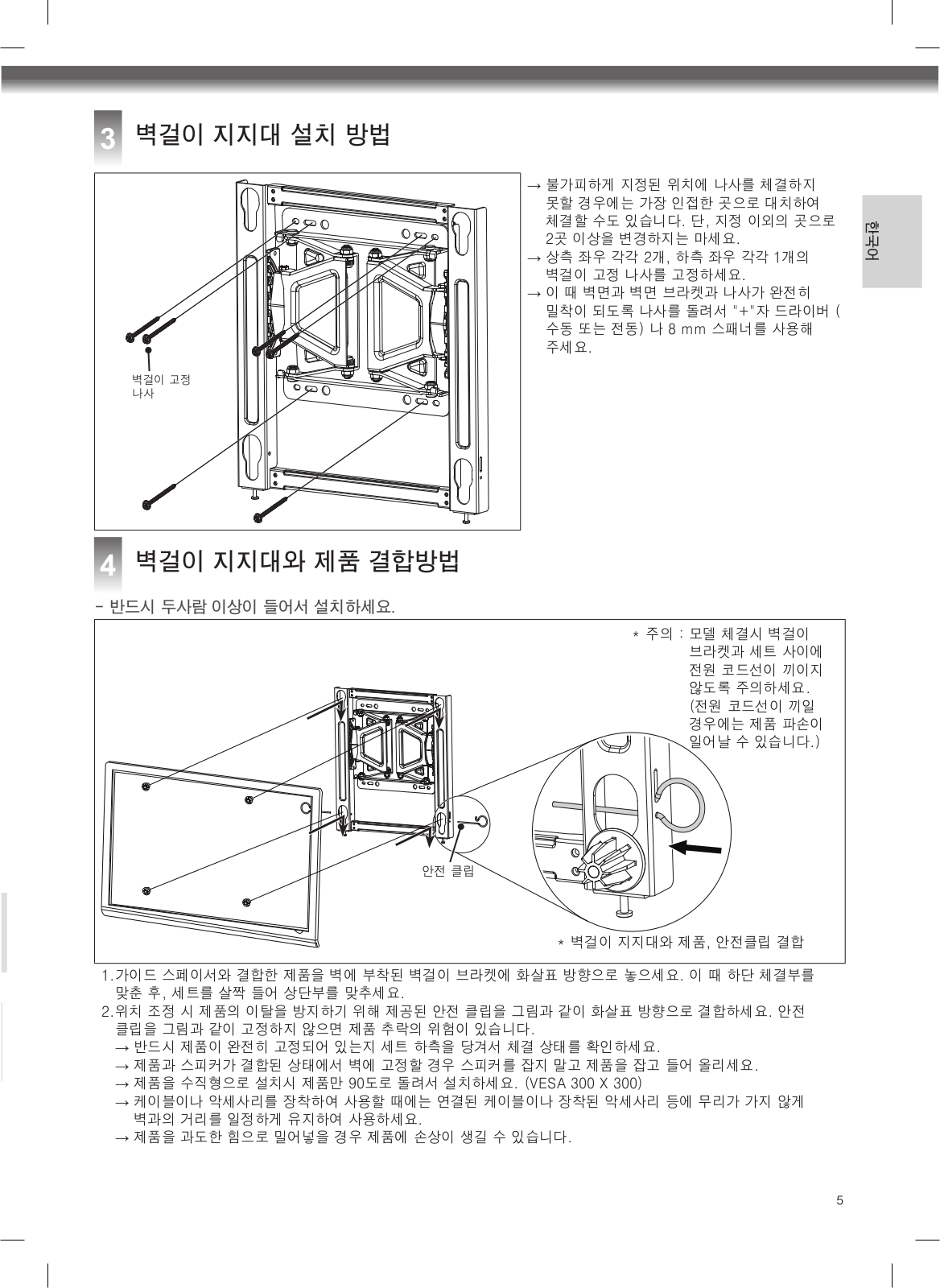
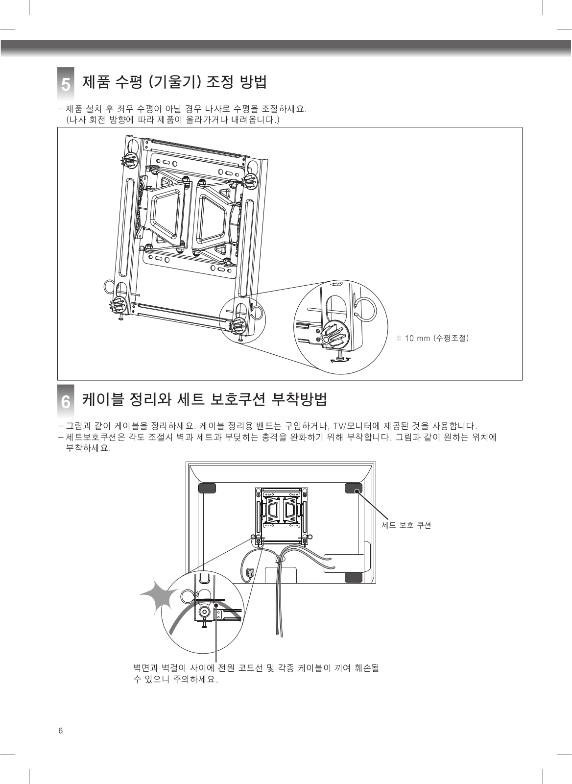
LSW350B
instruction manual [ja]
8 pgs
5.89 Mb
0
User guide
8 pgs
3.58 Mb
0
User guide [ru]
8 pgs
3.61 Mb
0
User Manual
90 pgs
37.42 Mb
0
User Manual [es]
8 pgs
3.58 Mb
0
Table of contents
Loading...
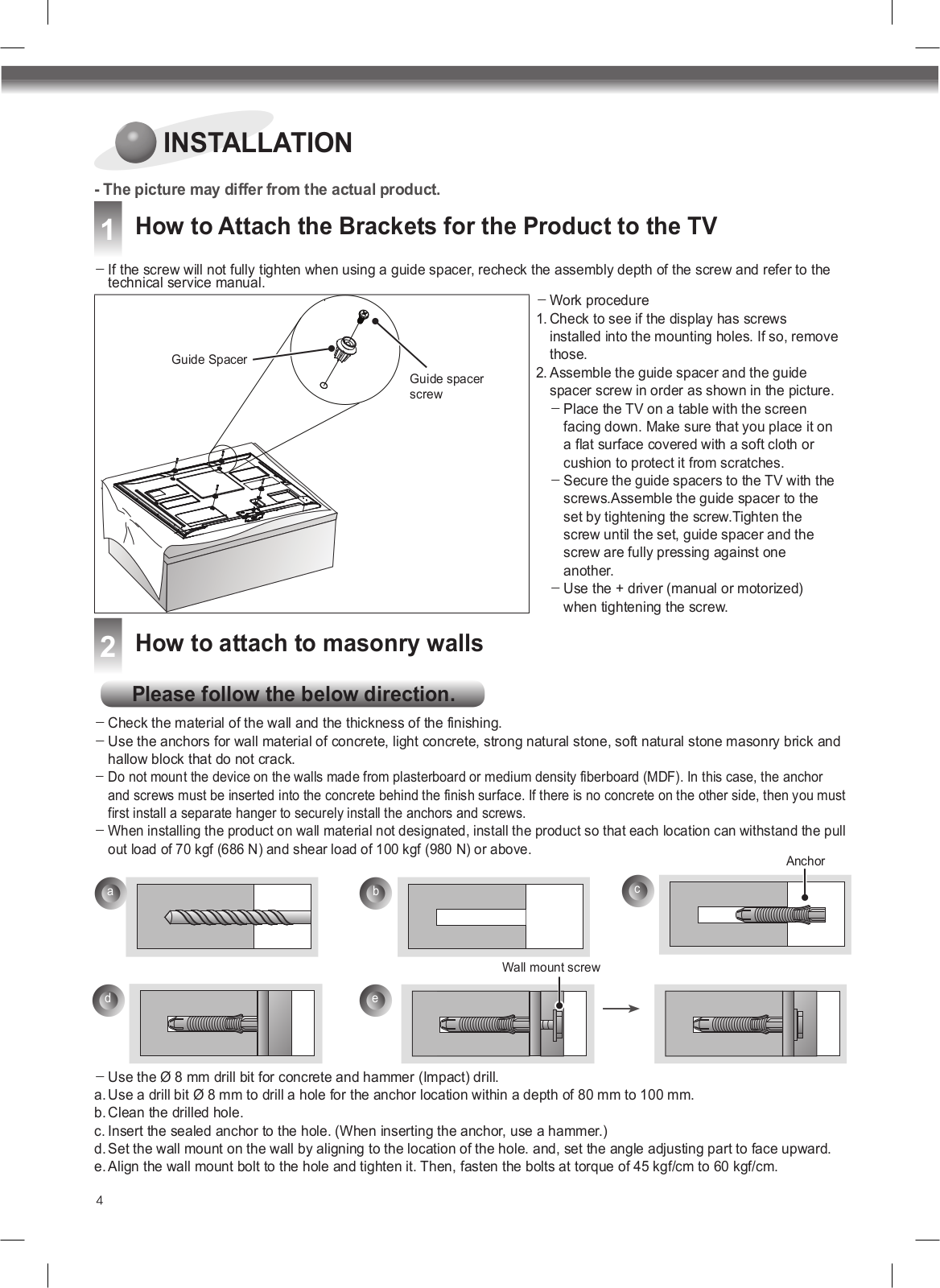
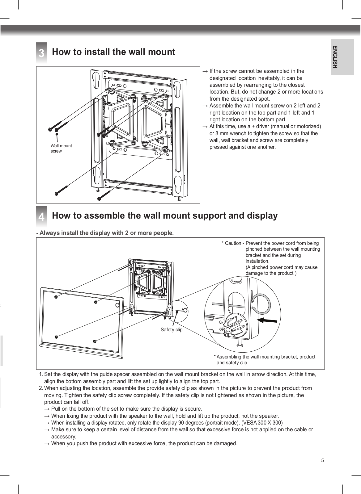
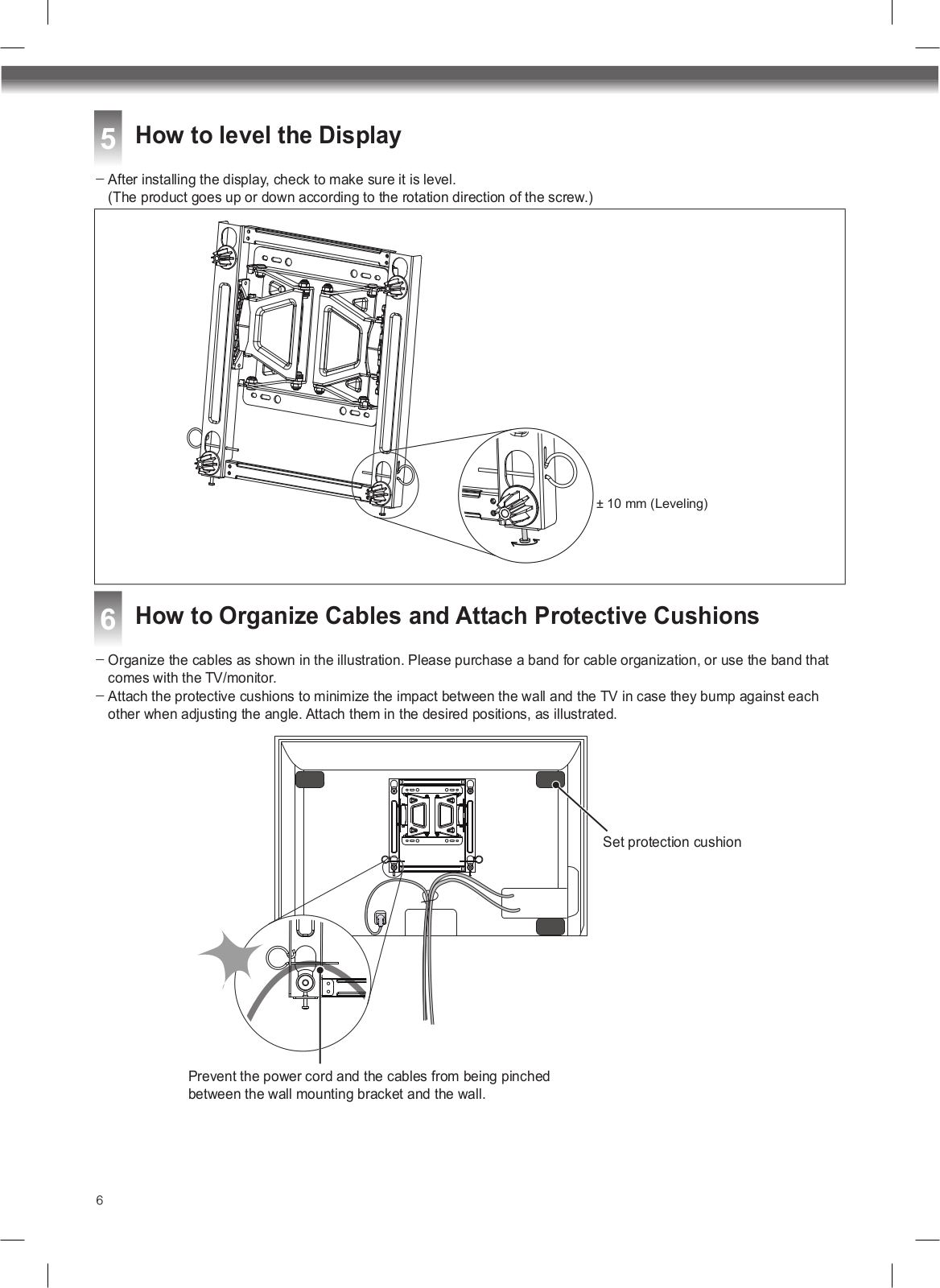
LG LSW350B User Manual
...
LG User Manual
Download
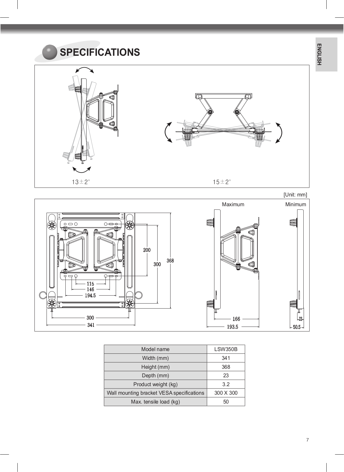
Specifications and Main Features
Frequently Asked Questions
User Manual
Download
Loading...
+
hidden pages
Unhide
You need points to download manuals.
1 point = 1 manual.
You can buy points or you can get point for every manual you upload.
Buy points
Upload your manuals
 Loading...