

Page 1

OWNER’S MANUAL
Smart Station
Please read this manual carefully before operating
your set and retain it for future reference.
MODELS
LSS464
P/NO : MFL
Page 2

2
Contents
1
Introduction
4 Features
5 Recommended PC Requirements
5 Before install the Smart Station
program
2
Getting Started
6 Install the Smart Station on your
PC
6 Starting the Smart Station
7 Smart Station Overview
8 Menu Bar
10 Tool Bar
11 Function windows
11 Status bar
11 Pop-up menu
12 Live window icons
13 Add the device manually
13 Edit the device
14 Remove the device
14 Create a device group
14 Create a new group folder
14 Delete a group folder
14 Edit a group folder
15 Add the device to the
group folder
15 Connect the device
15 Connect the group device
15 Disconnect the device
16 Device setup
16 Confi guration menu
overview
17 System settings
19 Video & Audio settings
22 Network settings
25 User settings
27 Schedule settings
30 Event settings
33 VA(Video Analytics) settings
(option)
38 Event (VA Rule) Setup
3
Operation and settings
13 Register the device
13 Add the device using
search function
38 Open the rule setting
window
38 Rule settings
39 Event settings
41 Station Setup
41 Recording Setting
Page 3

43 System Setting
45 Schedule Setting
47 Recording and Playback
47 Manual recording
47 VA recording
47 Motion recording
48 Schedule recording
48 Search and Playback
49 Export
50 Export Setting
51 EMap
51 EMap Overview
53 PTZ control
56 Log Search
3
57 LG Smart Player
58 Using the IP Utility
58 Starting the IP Utility
58 IP Utility Overview
4
Reference
60 Troubleshooting
65 Open source software notice
Page 4

4 Introduction
1
Introduction
The LG Smart Station is an IP-Surveillance software that works with the LG Video Server and LG
he LG Smart Station is an IP-Surveillance software that works with the LG Video Server and LG
IP cameras to provide video monitoring, recording setting and event management functions.
The software has multiple search functions for recorded events. Remote viewing and playback
are also possible with the use of the Smart Station.
This manual contains instructions on how to use and manage the LG Smart Station in your
networking environment. Some knowledge of networking environments would be beneficial
to the reader.
Should you require any technical assistance, please contact authorized service center.
Features
The LG Smart Station offers the following functions:
Remote setup available for LG IP device.•
Video recording with NAS system and Local HDD drive.•
EMap support•
Device Finder•
Intelligent Video Analytics Function•
Motion detection Function•
64 channels live view •
Multiple playback at the same time•
Camera Pan/Tilt/Zoom Control•
2way audio support•
User Privileges•
AVI File Export•
Various Layout and Intuitive User-Friendly GUI•
Page 5

Recommended PC Requirements
The LG Smart Station must be installed below operating systems for best performance and
stability.
Items Requirements
Operating System Windows XP Professional Service Pack 2 or above
CPU Intel Quad Core 2 Q6700 (2.66GHz) or above
Web Browser Microsoft Internet Explorer 6.0 or above
DirectX DirectX 9.0 or above
Memory 2GB or above RAM
Graphics Card 256 MB or above Video RAM (Use latest graphics card driver.)
Resolution 1280 x1024 (with 32bit color) or above
5Introduction
Network
100 Megabit Network
(Gigabit Network recommended for larger systems)
Before install the Smart Station program
The description pictures may differ from your OS (Operating System) or Web Browser type. •
The pictures used in this manual are based on Windows XP Professional.
Do not use other applications with this Smart Station program. This can cause memory •
shortage and program malfunction.
Check that the LG IP Device is(are) connected to the network and that power is supplied.•
For more information on product installation, see the user manual of your LG IP device.•
Page 6

6 Getting Started
C
2
Getting Started
Install the Smart Station on your PC
nstall the Smart Station on your P
You can install the Smart Station software following steps.
1. Insert the Client Program CD which will be started automatically.
If the disc does not run automatically on your PC, open the Client Program CD and
install the program manually.
2. Run the install file and install the programs to your computer following the on-screen
instructions.
3. After finishing installation, you will find the programs in the start menu or on the desktop.
Starting the Smart Station
1. Run the Smart Station program. To launch Smart Station, select LG Smart Station
from your Start > Programs > LG Electronics > Smart Station > Station > LG Smart
Station or click the LG Smart Station icon on your desktop.
The authorization window is displayed.
2. Enter the user ID and password. (Note that the default user ID and password are
“admin”.)
3. Click the [OK] button and then the LG Smart Station window is displayed.
Page 7
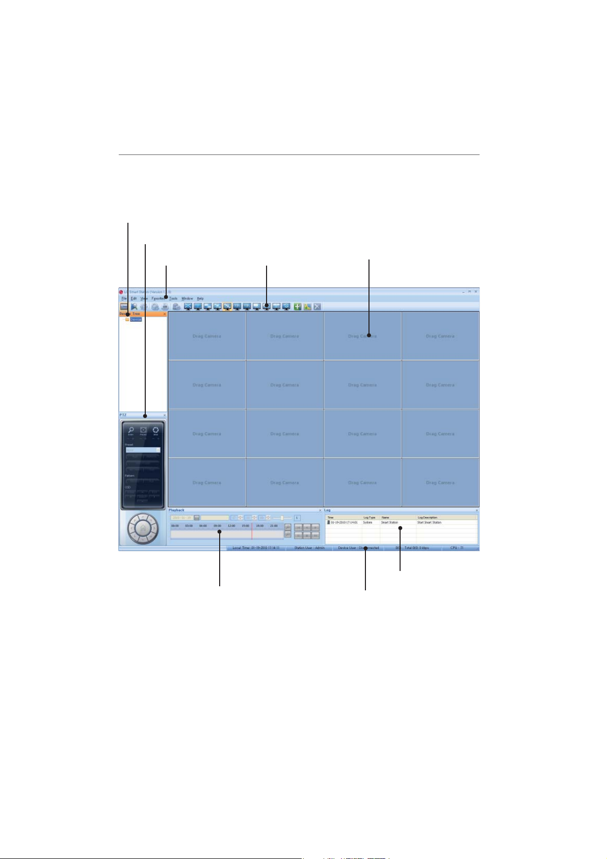
Smart Station Overview
Device Tree window
PTZ Control window
Menu Bar
Tool Bar
7Getting Started
Live window
Playback Control window
Log window
Status bar
Page 8
8 Getting Started
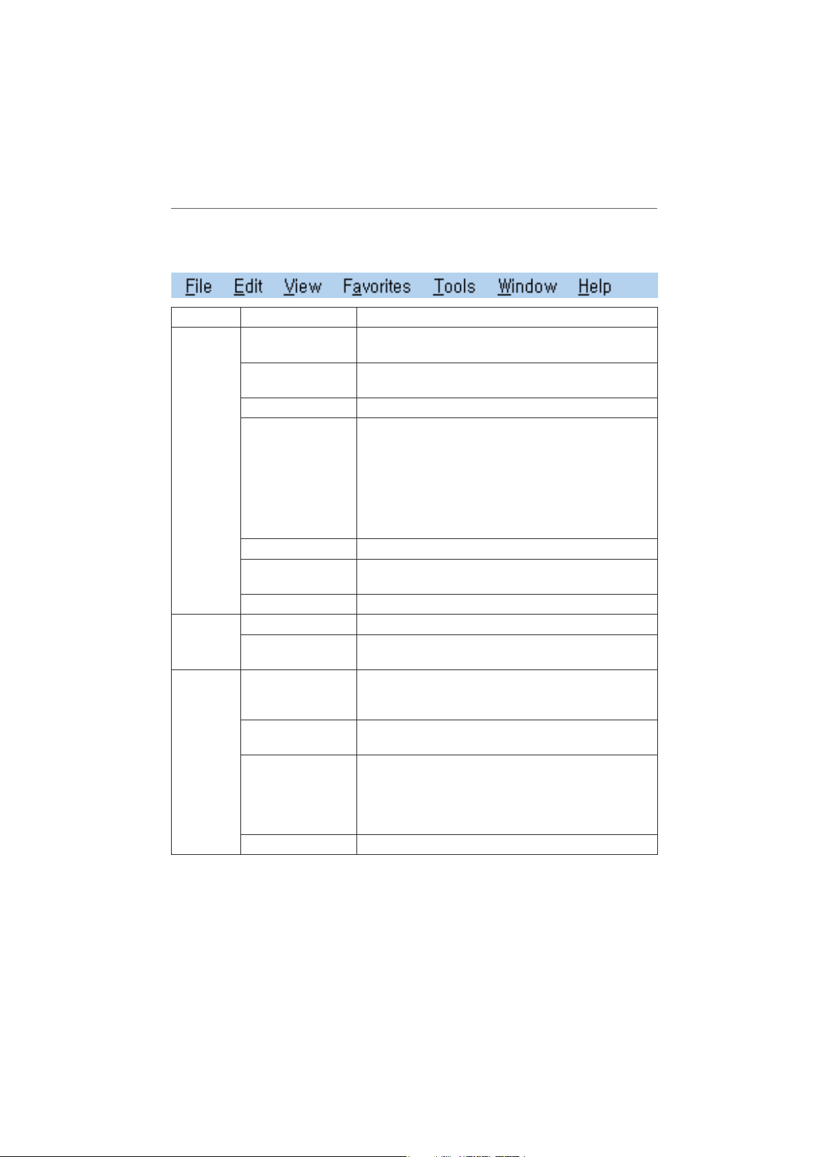
Menu Bar
Menu Sub-Menu Description
File Print You can print the current live image of the selected
Edit Delete Channel Delete the selected channel.
View Toolbar / Status
channel.
User Log-in Selects when you log-in the Smart Station or change
the authorized use.
User Log-out Selects when you want to log-out.
JPEG Saving You can capture and save the current image by JPEG file
format of the selected channel. The save folder is “Root
Drive:\LG Exported Files\JPEG”.
1. Select the channel.
2. Select File > JPEG Saving option. Jpeg Saving win-
dow is displayed.
3. Specify a location and filename, and click [Save].
Connect All Connect all devices of the current screen division mode.
Disconnect All Disconnect all devices of the current screen division
mode.
Exit Exit the Smart Station
Delete Channel All Delete the all channels of the current screen division
mode.
Displays or removes the selected function window.
/ PTZ / Tree /
Playback / Log
OSD Displays or removes the OSD in the selected channel
window.
Sequence View all the channels in sequence in the selected screen
division mode. You cannot use sequence mode with
the 64 split. While the sequence mode condition, if you
change the screen division mode, the sequence function will be canceled.
Language Select the language for Smart Station.
Page 9

Favorites Add to Favorites You can add the current status of the camera mapping
and screen mode to the Favorites menu bar.
1. Select Favorites > Add to Favorites to Favorites
options when you add it to the favorites menu.
2. Type a name for the favorites.
3. Click [OK].
Organize Favorites
Tools Add/Edit/Remove
Device
Station Setup Set the Recording and System options for the Smart
EMap This function gives a visual overview of the cameras
Log Search You can search log history. Logs shows all events and
Window Window1
(17ch~32ch)
Window2
(33ch~48ch)
Window3
(49ch~64ch)
Live Popup Displays the popup window for EMap or log.
Help About Smart Station Displays the Smart Station Information.
Selects when you want to rename or delete the favorite
item.
To rename the favorite item.
1. Select Favorites > Organize Favorites options.
2. Select the favorite item from the favorite list.
3. Type a new name in the [Name] option.
4. Click the [Rename] button to confirm it.
5. Click the [OK] button to exit.
To delete the favorite item.
1. Select Favorites > Organize Favorites options.
2. Select the favorite item from the favorite list.
3. Click the [Delete] button to confirm it.
4. Click the [OK] button to exit.
Add, edit or remove devices in Smart Station.
Station.
in your surveillance environment using the imported
maps.
user actions.
Displays from the 17 channel to the 32 channel in the
one popup window.
Displays from the 33 channel to the 48 channel in the
one popup window.
Displays from the 49 channel to the 64 channel in the
one popup window.
9Getting Started
Page 10
10 Getting Started
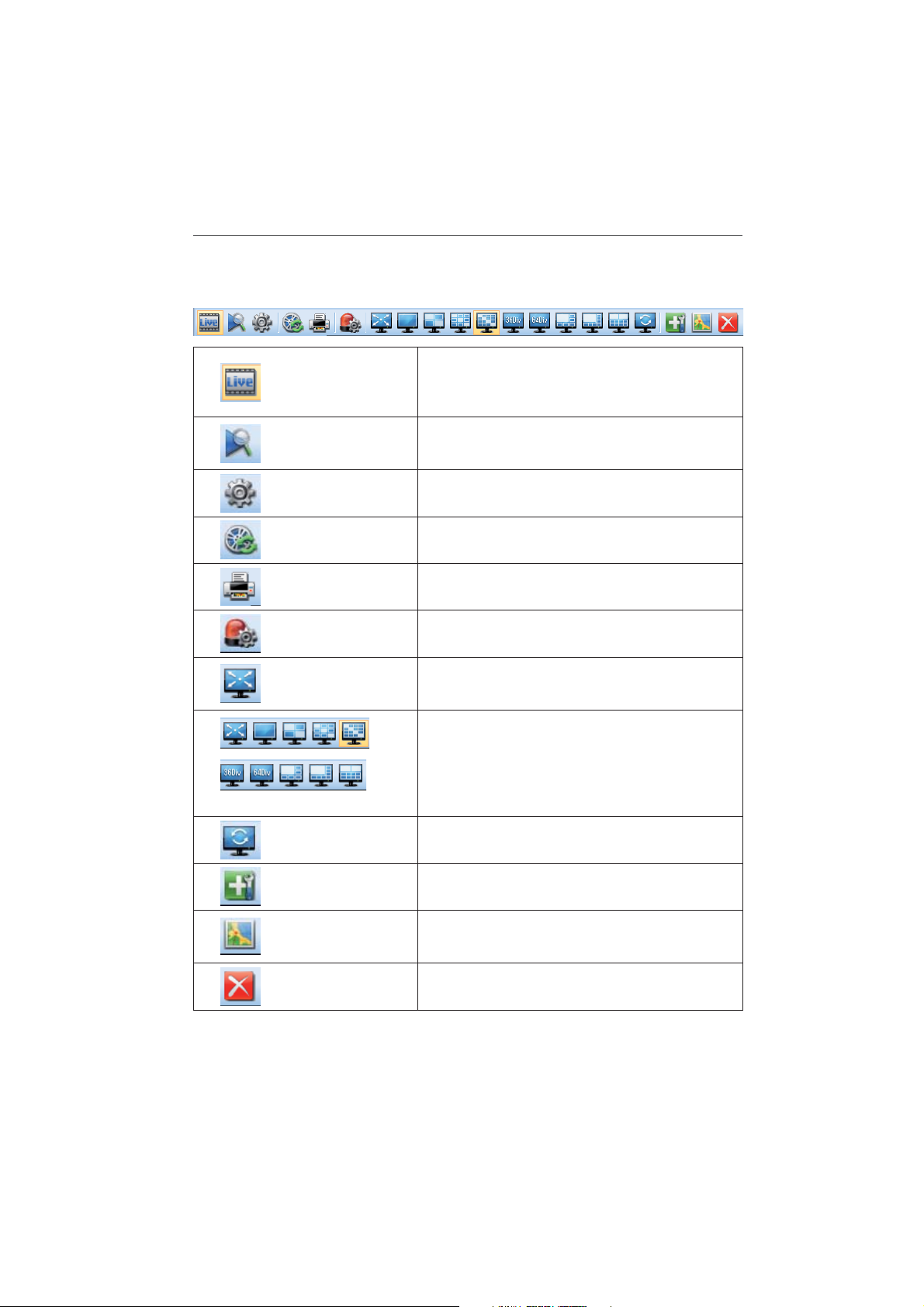
Tool Bar
Live
Search
Device Setup
Displays the live view workspace. You can see the
surveillance camera’s images in the window(s). You
can also control the PTZ camera, playback the data or
view the system and event log list.
Displays the search workspace. You can search and
play the recorded data using the Date/Time or Event
search functions.
You can set the configuration of the selected device in
the Device Tree window via the network.
Export to AVI
Print
Video Analytics
Full Screen
Division
Sequence
Add/Edit/Remove Device
Emap
Delete Channel
Displays the Export pop-up windows.
You can print the current live and playback image of
the selected channel.
Displays the VA ( Video Analytics) event setting popup windows.
You can view the live window in full screen mode. To
return to the normal screen, press the [Ecs] button on
the keyboard.
When the icon is clicked, the screen will be changed
to split mode and if the icon is clicked again, the
screen will be changed by sequence (except 64 split
mode). Choose the screen division mode.
View all the channels in sequence. You cannot use
sequence mode with the 64 split.
Displays the Add/Edit/Remove Device pop-up windows. Add, edit or remove device in Smart Station.
Displays the EMap pop-up windows. This function
gives a visual overview of the cameras in your surveillance environment using the imported maps.
Delete the selected channel.
Page 11
Function windows
Device Tree window
Displays the registered device name and group folder name.
To show or hide a structure level, click the plus (+) or minus (-) signs at the left of the corresponding structure.
PTZ Control window
You can control the PTZ unit that the unit connected to the selected device using these buttons.
Playback Control window
You can playback the recorded data of the selected channel.
Log window
Displays the events and user actions. The log is saved in the “Smart station installed folder\log”
folder per each day. You can search the logs by using log search function.
If you click the right mouse button, the pop-up menu is displayed.
Clear All : All logs are deleted in the log view list. •
Live Popup : Live video will be popup.•
Status bar
11Getting Started
Local Time: Displays the Local Time.•
Station User: Displays user level to the smart station.•
Device User: Displays the connected user to the selected device. •
Framerate/Bitrate: • Displays the Frame rate and Bit rate per second of the selected device.
CPU: Displays the present CPU usage of the client PC.•
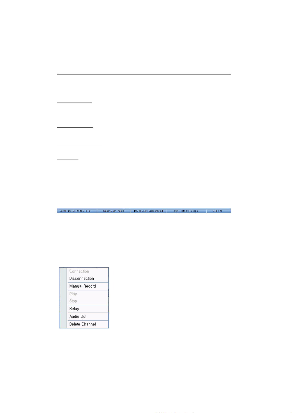
Pop-up menu
Connection: Select to connect the device.•
Disconnection: Select to disconnect the device.•
Manual Record: Select to record manually.•
Play: Select to play the recording data.•
Stop: Select to stop the playback.•
Relay: Select to run the relay of the device.•
Audio Out: Select to activate the two-way audio.•
Delete Channel: Select to delete the registered device.•
Page 12
12 Getting Started
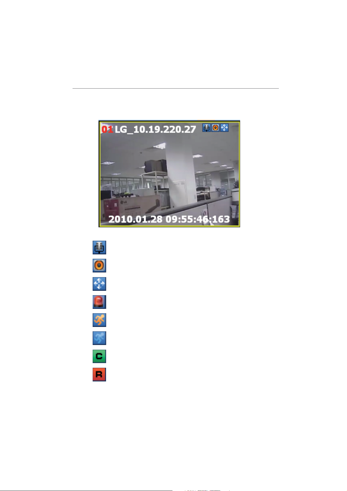
Live window icons
Icons Discription
Displays when the audio input function is available in the
network device.
Displays when the audio funciton is activated in the network
device.
Displays when the PTZ device is connected.
Indicates sensor recording.
Indicates motion detection recording (Yellow icon).
Indicates VA recording (Blue icon).
Indicates Continuous recording.
Indicates instant recording.
Page 13

3
Operation and settings
Register the device
egister the device
The first time Smart Station is started, you should register a LG IP device to control it by the
Smart Station.
Note:
The computer running Smart Station must be on the same network with device.
Add the device using search function
1. Select Tools > Add/Edit/Remove Device option on the menu bar.
2. Click the [Search] button. After a few seconds the found device is(are) displayed.
3. Select the device name in the Device list. If you want to register the all devices, check the
[Select All] option.
4. Click the [Add] button. The Add Device window is displayed.
5. Specify the Device Name, Video Stream, Protocol, User ID, Password and click the [OK] button.
6. Click the [OK] button repeatedly to exit the window.
The registered device name is displayed in the Device Tree windows.
13Operation and settings
Add the device manually
1. Select Tools > Add/Edit/Remove Device option on the menu bar.
2. Click the [Add] button. The Add URL window is displayed.
3. Specify the device Name, Video Stream, Protocol, User ID, Password and click the [OK] button.
4. Click the [OK] button to exit the window.
The registered device name is displayed in the Device Tree windows.
Edit the device
1. Select Tools > Add/Edit/Remove Device option on the menu bar.
2. Select the device name on the device list.
3. Click the [Edit] button. The Edit Device window is displayed.
Page 14

14 Operation and settings
4. Specify the Device Name, Video Stream, Protocol, User ID, Password and click the [OK] button.
5. Click the [OK] button to exit the window.
Remove the device
1. Select Tools > Add/Edit Device option on the menu bar.
2. Select the device name on the device list.
3. Click the [Remove] button. The selected device is removed.
4. Click the [OK] button to exit the window.
Create a device group
You can make the device group to manage it.
Create a new group folder
To create a group under the Device top-level folder, do the following on the Device Tree section:
1. Click the right mouse button on the Device or group folder.
2. Select the [Add Group] option. The dialog window is displayed.
3. Overwrite the default name “New Group” with a group name of your choice.
4. Click the [OK] button to confirm it.
The new group folder is created under the folder you selected.
Delete a group folder
1. Select the required group folder and click the right mouse button.
2. Select the [Delete Group] option.
Notes:
It is not possible to delete the Device top-level folder. •
Deleting a group folder will delete all subgroup folders within the group folder as well. •
If you delete the group folder, the device in the group folder will be moved to the upper
group folder automatically.
Edit a group folder
1. Select the required group folder and click the right mouse button.
2. Select the [Edit Group] option. The dialog window is displayed.
3. Overwrite the existing group name with a new name of your want.
Page 15

4. Click the [OK] button to confirm it.
Note:
You cannot edit the Device top-level folder.
Add the device to the group folder
1. Select the required device name that you want to group.
2. Click the device name then drag and drop to the group folder.
3. Repeat steps 1 to 2 to group the other devices.
Connect the device
1. Select the required device name.
2. Drag and drop the device name to the required position in the live window.
The device is connected automatically and the Live image is displayed in the selected window.
3. Repeat step 1 to 2 to connect the other devices.
15Operation and settings
Connect the group device
1. Select the required device group folder.
2. Drag and drop the device group folder to the required position in the live window.
Each devices are connected automatically and the Live image is displayed in each windows.
3. Repeat step 1 to 2 to connect the other devices.
Disconnect the device
1. Select the device channel.
2. Click the right mouse button on the live window. Select [Disconnection] option.
The device of the selected channel is disconnected. If you want to connect again, click the
right mouse button and select [Connection] option.
3. Repeat step 1 to 2 to connect the other devices.
Page 16

16 Operation and settings
Device setup
You can setup the selected device via the network.
1. Select the live window of the device to setup what you want.
2. Click the Device setup icon.
3. Set the options. For more detail settings, see the next pages.
Con guration menu overview
The following table shows the list of menu items.
Main Menu Sub Menu
Version & Language
System
Video Audio
Network
User
Schedule
Event
VA
Advanced Parameters
Log
Date & Time
Maintenance
Video
Audio
PTZ
Basic
RTP stream
TCP/IP
Notification
DDNS Server
IP filtering
Encryption
Basic
User List
Total Schedule List
Schedule List
Recording server
Event List
Event server
Sensor & Relay
Fan
Preset Mode
OSD
Filter
Basic Parameters
Page 17
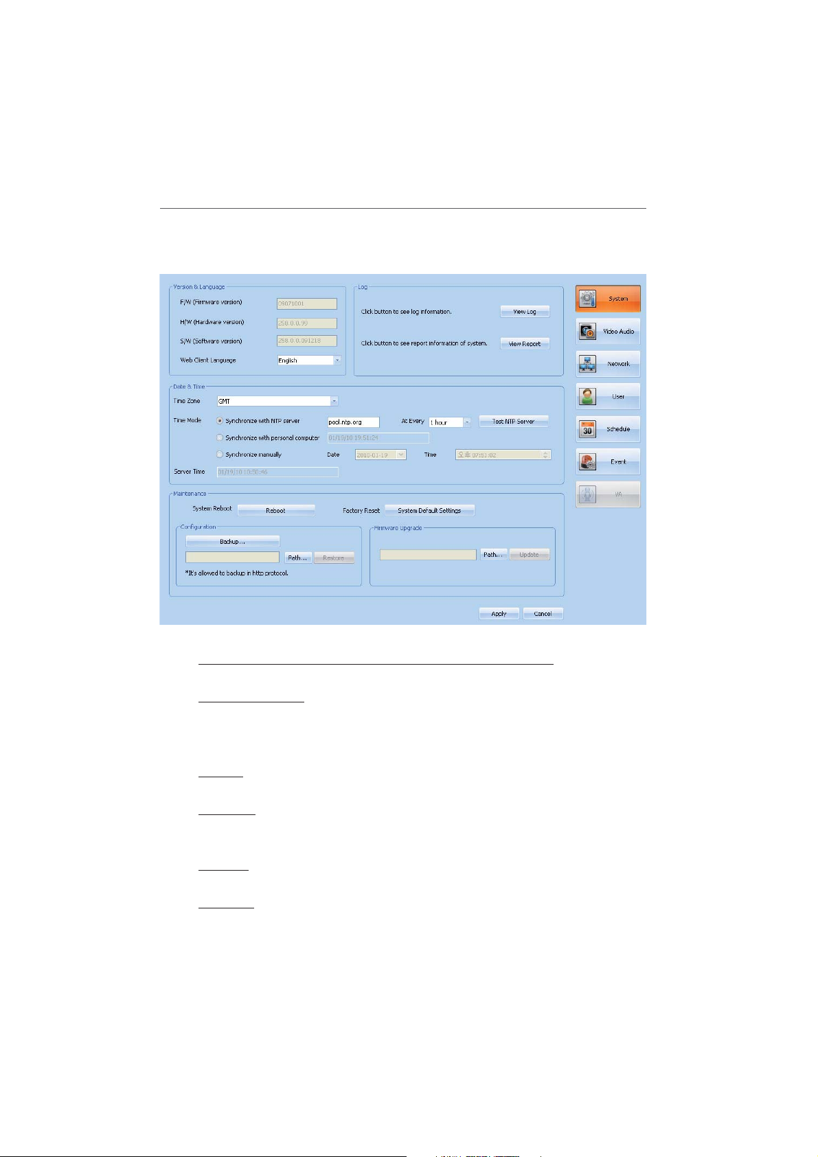
System settings
17Operation and settings
Version & Language
F/W (Firmware version), H/W (Hardware version), S/W (Software version)
Displays the current Firmware, Hardware, Software version.
Web Client Language
Select a language for the Web Client configuration menu and information display.
Log
The System log provides a summary of the status of the selected LG IP device.
View Log
Click this button to display the system log information.
View report
Click this button to display the report window of the system.
Date & Time
Time zone
Select your time zone from the drop-down list.
Time mode
Synchronize with NTP Server: The LG IP device will obtain the time from an NTP >
server every selected time. Specify the NTP server’s IP address or URL. Click the
Page 18

18
Operation and settings
Server Time
Displays the server time.
Maintenance
Notes:
System Reboot, Factory Reset, Configuration restore, Firmware upgrade contains •
operation of “camera reboot”. Therefore connection is disconnected and all of camera
operation is disabled. If network setting of camera is “Static”, connection will be automatically reconnected after camera reboot completed. But if network setting of camera is “DHCP”, IP address of camera may be changed. For register to device , remove list
of changed device and search by “Add/Edit/Remove Device”.
Firmware upgrade contains file uploading and camera reboot and therefore it will may •
takes a few minutes.
System Reboot
Click the [Reboot] button to restart the system. Use this method if the unit is not performed as expected.
Factory Reset
Click the [System Default Settings] button to reset the factory default values (Except
the Network settings, PTZ Protocol and Preset settings). The [System Default Settings]
button should be used with caution.
Configuration
Firmware Upgrade
[Test NTP Server] button to test the server.
Synchronize with personal computer: Set the time from the clock on your com- >
puter.
Synchronize manually: This option allows you to manually set the time and >
date.
Backup: To take a backup of all of the settings. If necessary, it is then possible >
to return to a previous configuration if settings are changed and there is unexpected behavior.
Restore: >
1. Click the [Path] button.
2. Find and locate the saved backup file.
3. Click the [Restore] button then confirmation window is displayed.
4. Click the [OK] button and then the system settings will be restored to the
previous configuration and reboot the system.
Notes:
Backup and Restore can only be used on the same unit running the same •
software version. This feature is not intended for multi-configurations or for
firmware upgrades.
Configuration Backup is supported only http protocol, not https.•
You can update the system manually.
Page 19
Operation and settings
1. Click the [Path] button.
2. Find and open the firmware file.
3. Click the [Update] button to update the firmware.
Note:
After completing the settings on this page, click [Apply] button to confirm the settings.
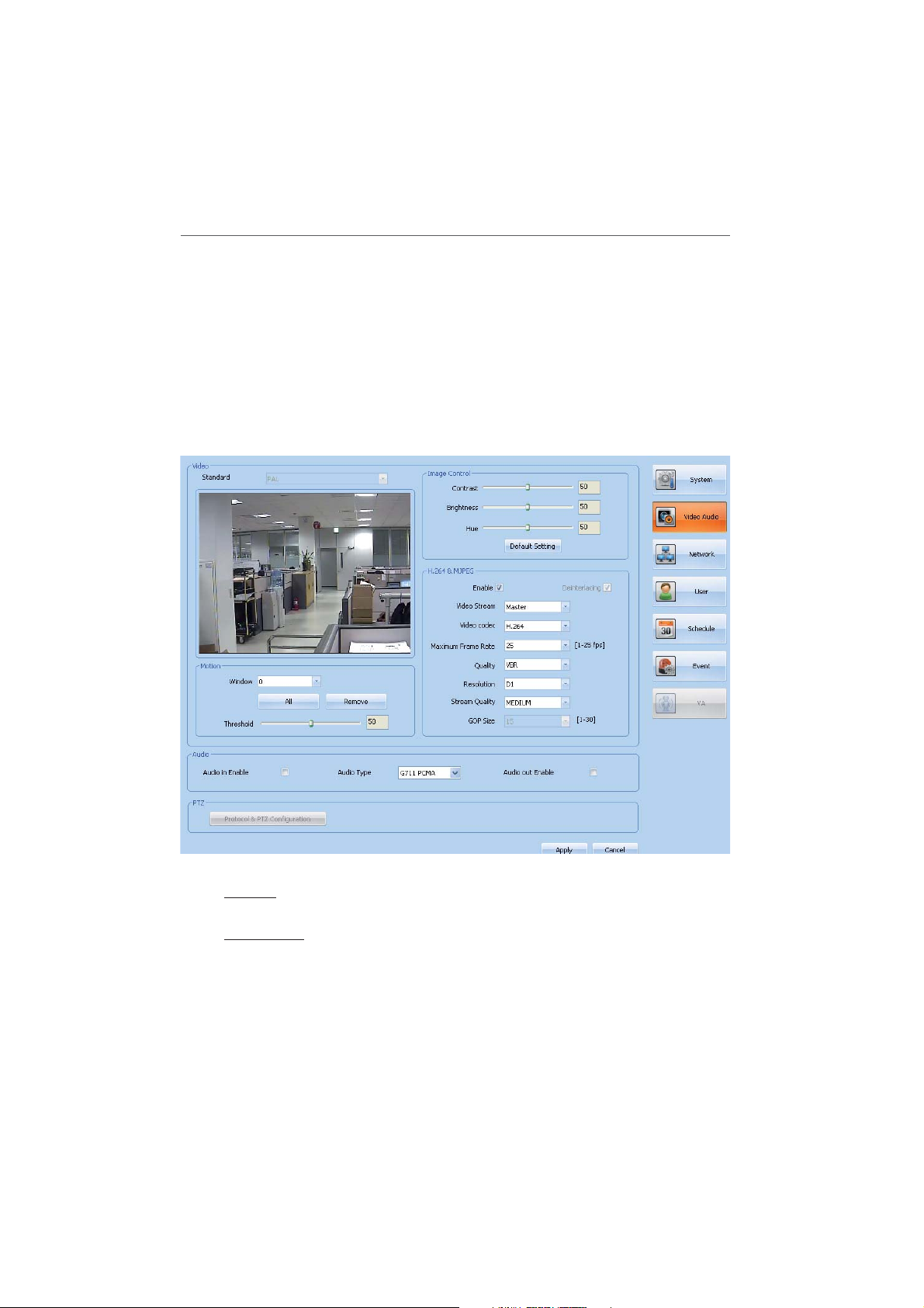
Video & Audio settings
19
Video
Standard
Displays the video system of the camera.
Image Control
Contrast: Select the contrast value. >
Brightness: Select the brightness value. >
Hue: Select the Hue value. >
Default Setting: Click this button to reset the default option to its original factory •
settings.
Page 20

20
Operation and settings
H.264 & MJPEG
Enable: Click to activate the stream function. >
Deinterlacing: Click to use the deinterlacing function. >
Video Stream: Select the video stream between Master and Slave. >
Video Codec: Select the video codec between H.264 and MJPEG. >
Maximum Frame Rate: Select the frame rate. >
NTSC 1 to 30 (fps)
PAL 1 to 25 (fps)
Quality: Select the Quality. >
VBR: The bit rate may vary depending on the complexity of the video to meet the selected quality.
CBR: The video quality may vary in order to preserve a constant bit rate. -
Resolution: Select the resolution of the video stream. >
NTSC
PA L
Stream Quality: If the [Quality] option set to VBR, this option is displayed. Select >
the network stream quality. (Highest, High, Medium, Low and Lowest)
Bit rate: If the [Quality] option set to CBR, this option is displayed. Enter the bit >
rate. Edit the bit rate value from 64 ~ 10240kbps.
GOP Size: Select the GOP size. This setting is valid for H.264. >
Motion
Motion detection window is used to detect movement of the object in the video image.
Motion detection is used to generate an event whenever movement occurs in the video
image. A total of 5 motion detection windows can be configured.
How to set the motion detection event
1. Select Motion Detection window number from the drop-down list.
2. Click one point with the left mouse button on the preview window and drag &
drop to adjust the desired size. The Motion detection window will appear in the
preview window. If you set to all area, click the [All] button.
3. Set the [Threshold] option.
Notes:
You can reset the size and position of the Motion detection window. Click one of the dot
point and drag & drop to adjust the motion detection area. Click the Motion detection
window and drag to the desired position.
If you want to delete the Motion detection window, select window number and click the
[Remove] button.
D1 (720 x 480), HALF D1 (720 x240),
CIF (352 x 240) and QCIF (176 x 120)
D1 (720 x 576), HALF D1 (720 x288),
CIF (352 x 288) and QCIF (176 x 144)
Page 21

Operation and settings
Audio
Audio in Enable
Click to use the audio in function.
Audio type
Select the audio encoding type. (G711 PCMU, G711 PCMA, G726 24K, G726 32K)
Audio out Enable
Click to use the audio out function.
PTZ (option)
Protocol & PTZ Configuration
Click the [Protocol & PTZ Configuration] button to display the Protocol & PTZ setting
window.
Protocol Setting
PTZ Driver >
Follow the instructions below to upload PTZ protocol.
1. Click the [...] button, find and open the file.
2. Click the [Upload PTZ Protocol] button and then the PTZ protocol will be
added.
Protocol: Displays the selected PTZ protocol. You can select the other PTZ pro- >
tocol from the drop-down list.
Edit: Click to displays the selected PTZ protocol window to check the detail option range.
Remove: Click to remove the selected PTZ protocol. -
Note:
The PTZ option range differs depending on the PTZ cameras.
Baud rate: Select the desired speed of communication between the IP device >
and the PTZ device. Confirm selected parameter to the baud rate of the IP
device.
Data bit: Set the number of the data bits for RS-485/422 communication >
Parity: Select the desired parameter. The parity bit, added to the data, to per- >
form parity check.
Stop bit: Enter the desired parameter. The stop bit, added to the last of data, in >
asynchronous communication.
Save• : Click to confirm the settings.
Configuration Setting
Click the [Configuration Setting] button to see the PTZ configuration.
Enable: Click to use the PTZ protocol. >
Camera ID: Enter the PTZ camera ID. Make the same ID as the PTZ camera. >
Pan speed: Enter the panning speed of the PTZ camera. >
Tilt speed: Enter the tilting speed of the PTZ camera. >
21
Page 22

22 Operation and settings
Focus speed: Enter the focus speed of the PTZ camera. >
Zoom speed: Enter the zoom speed of the PTZ camera. >
Preset tour park time: Enter the parking time. >
Save: Click the [Save] button to confirm the settings. >
Note:
After completing the settings on this page, click [Apply] button to confirm the settings.
Network settings
Basic
MAC address: Displays the MAC address. >
Web Port: The default HTTP port number (80) can be changed to any port >
within the range 1025-65535.
RTSP Port: The RTSP protocol allows a connecting client to start an video >
stream. The default setting is 554, and the allowed port range is 1025-65535.
Notes:
The RTSP port number should not be same with the web port number.•
If you change the RTSP port, the current connection is disable and you •
should remove and re-register the device in the “Add/Edit/Remove Device”.
TTL: Set the TTL(Time To Live) value. The default setting is 7, and the allowed >
Page 23

Operation and settings
TTL range is 1-255.
Enable ARP Ping: If you want enable to ARP Ping setting by IP Utility, check to >
“Enable ARP Ping”.
RTP stream
RTP (Real-time Transport Protocol) is an internet protocol that allows programs to manage
the real-time transmission of multimedia data, via unicast or multicast.
Video Stream
Selects the Video Stream from the drop-down list.
RTP unicast
Select when use the RTP unicast.
RTP multicast
Select when use the RTP multicast.
Multicast IP: Set the IP address for RTP multicast. The allowed IP address range >
is 224.0.0.0 - 239.255.255.255.
Video Port: Set the Video RTP port number. The allowed port range is 1025- >
65535.
Audio Port: Set the Audio RTP port number. The allowed port range is 1025- >
65535.
Data Port: Set the VA RTP port number. The allowed port range is 1025-65535. >
Note:
Each stream using multicast needs its own a pair of multicast IP address and port numbers to avoid address conflict.
TCP/IP
DHCP
Select when using the DHCP function. Network settings of this unit are configured
automatically by the DHCP server.
Static IP
Assign the IP address manually.
IP address: Enter an IP address. >
Subnet mask: Enter a subnet mask address. >
Gateway: Enter the gateway address. >
DNS server: Enter the DNS server address. DNS (Domain Name Service) pro- >
vides the translation of domain name to IP addresses on your network.
Secondary DNS server: Enter the Secondary DNS server address. >
Note:
If you change the IP Address or Type (Static b DHCP, DHCP b Static), the device
connection is disconnected and all of operation is disabled. To connect the device
again, remove and re-register the device using the “Add/Edit/Remove Device”
menu.
Apply: Click to confirm the settings.•
23
Page 24

24 Operation and settings
Notification
Notify to SMTP server, if IP address is changed >
If you select this option, notify the user about changed IP address information
by E-mail.
Notes:
You should register the SMTP server on the Event server setting to set this •
function.
This function is activated when you select DHCP option in the TCP/IP set-•
ting.
DDNS Server
This free service is very useful when combined with the LG DDNS Server. It allows the user
to connect the LG IP device using the URL, rather than an IP Address. This also solves the
problem of having a dynamic IP address.
Don’t use DDNS server
Select when disable the DDNS function.
Use DDNS server
Select when enable the DDNS function.
Provider: Displays the DDNS provider. >
Hostname: Enter the hostname you want to use. >
Note:
If you change the Hostname of the device, you must remove and re-register
the device to connect again using the “Add/Edit/Remove Device” menu.
IP filtering
The access of the IP addresses in the list are allowed or denied according to the choice
made in the drop-down list of the Basic policy option. The administrator can add up to 10
IP address entries to the list (a single entry can contain multiple IP addresses). The users
from these IP addresses need to be specified in the user list with the appropriate access
rights.
Basic policy:
Select the basic policy type.
Allow all: Allow all the IP address basically, but the IP addresses in the list are >
denied.
Deny all: Deny all the IP address basically, but the IP addresses in the list are >
allowed. It needs one or more an IP address to activate this function.
Add: Click to add the IP address.•
1. Click the [Add] button.
2. Set the IP options.
Alias: Enter the alias. -
From: Enter the start IP address for the IP filtering. -
To: Enter the end IP address for the IP filtering. -
Page 25

Operation and settings
Note:
If you want to deny or to allow a range of IP addresses, enter th start IP address
to “From” and the end IP address to “To”. You can also add an IP address by
entering the IP address to “From” and “To”.
3. Click the [OK] button.
4. Repeat the steps 1-3 to add additional IP address.
Remove: Click to delete the IP address.•
1. Select the alias from the list.
2. Click the [Remove] button. The IP address will be deleted.
Encryption
Select the HTTP or HTTPS option for security.
Note:
After completing the settings on this page, click [Apply] button to confirm the settings.
User settings
25
Basic
Enable login as custom user
Check the box to enable custom user login - allows the user access for only viewing the live stream image.
Maximum RTP stream connection
Page 26

26 Operation and settings
Maximum number of simultaneous stream connection. >
Set this number to limit the number of simultaneous stream connections.
Note:
Preview window of camera setting and preset setting are affected by this setting.
User list
Add the User
You can register a new user with various access rights.
1. Click the [Add] button. User Setting window is displayed.
2. Enter the new User ID and Password. (Minimum 4 length with alphabet and number).
3. Enter the password again to verify.
4. Select the authority and then click the [Save] to confirm your selection.
Administrator: Unlimited operation of the unit. (Access to the Configuration menu, and you can set the configuration options.)
Power user: Use of the limited functions of the system (The Configuration menu is not allowed. A power user can use the Live View, PTZ control, OSD
control and audio functions.
Normal user: Provides the lowest level of access, which only the live stream image view is available.
Custom user: The user can login and view the live stream image only when the “enable login as custom user” option is checked to enable it.
Edit the registered user
You can change the password or authority.
1. Choose the user ID and then click the [Edit] button.
2. Change the Password or Authority, then click the [Save] button to confirm your
selection.
Delete the registered user
1. Choose the user ID you want to delete.
2. Click the [Remove] button.
Notes:
Remember the password.•
The default administrator user ID ‘admin’, custom user ID ‘anoymous’ are perma-•
nent and cannot be deleted.
Note:
After completing the settings on this page, click [Apply] button to confirm the settings.
Page 27

Operation and settings
Schedule settings
A schedule recording can be activated at preset times, in a repeating pattern on selected
weekdays. If the recording server is not set, this function is not activated.
27
Total schedule List / Schedule List
To set the Recording Schedule
1. Click the [Add] button. Recording schedule setting window is displayed.
2. Set the [Pre alarm] and/or [Post alarm] option.
Pre alarm: Specify the pre-event recording time that records the situation until the input has been detected.
Post alarm: Specify the post-event recording time that records the situation after the input has been detected.
3. Select the [Repeat type] option and set the detail options. It can be configured
in 5 different ways, Repeat None, Daily, Weekly, Monthly and Yearly.
Custom day: If the [Repeat type] option set to [Monthly] or [Yearly], this option is displayed.
Schedule duration: If the [Repeat type] option set to [Repeat none], [Monthly] or [Yearly], this option is displayed.
4. Select the recode mode and set the recording schedule time using drag on the
time table.
Page 28

28 Operation and settings
None: No scheduled recording -
Continuity: Recording starts automatically from the preset time. -
Sensor: Recording starts automatically when the sensor input is activated within a designated time.
Motion: Recording starts automatically when motion is detected within a designated time.
VA: Recording starts automatically when the object or event is detected within a designated time.
C+S: Recording starts automatically from the preset time. When the input is activated within a designated time, change the continuous recording mode
to the sensor event recording mode and recording starts automatically.
M+S: Recording starts automatically when the sensor alarm signal has input or motion has been detected.
V+S: Recording starts automatically when the object or event is detected or the sensor input is activated within a designated time.
C+V: Recording starts automatically from the preset time. When the object or event has been detected within a designated time, change the continuous recording mode to VA event recording mode and recording starts
automatically.
C+M: Recording starts automatically from the preset time. When the motion is detected within a designated time, change the continuous
recording mode to motion event recording mode and recording starts
automatically.
C+V+S: Recording starts automatically from the preset time. When VA or SENSOR event is detected, change the continuous recording mode to the
VA event recording mode or the sensor event recording mode.
C+M+S: Recording starts automatically from the preset time. When Motion or Sensor event is detected, change the continuous recording mode to the
motion event recording mode or the sensor event recording mode.
5. Click the [Save] button to confirm the settings.
To edit the Recording Schedule
1. Choose the schedule in the Total schedule list or Schedule list.
2. Click the [Edit] button.
You can check or change the recording schedule options except for repeat
type.
To activate the Recording Schedule
1. Set the [Stream] option.
2. Choose the schedule in the Total schedule list and then click the [Allocate] button.
To deactivate the Recording Schedule
1. Choose the schedule in the Schedule list.
Page 29

Operation and settings
2. Click the [DeAllocate] button.
To delete the Recording Schedule
1. Choose the schedule in the Total Schedule list.
2. Click the [Remove] button.
Recording server
Recording server is used to save the recorded data files.
Recording Server
These options can be set using the Recording Storage Settings in the Station Setup
menu.
Disk full notification of recording server.
Run relay: Marks up to activate the alarm. Alarm is activated when the >
Recording Server fully recorded via relay output.
SMTP server: Select the SMTP server address. Sends an e-mail when the >
Recording Server fully recorded.
Note:
You should register the SMTP server on the Event server setting to set this
function.
Note:
After completing the settings on this page, click [Apply] button to confirm the settings.
29
Page 30

30 Operation and settings
Event settings
Event List
An event will be started by some sort of external signal, such as sensor or video analytics
event.
To edit the Event Schedule
1. Click the trigger event in the event schedule list. Event schedule window is displayed.
2. Set the options.
Trigger: Displays the selected trigger event. -
Time: Sets the weekday, Start, End, Pre Alarm, Post Alarm and Ignore inter- val time options.
Action: Selects the options. This occurs when the event runs, for example, uploading of images to an FTP server, or e-mail notification.
Stream: Selects the stream of the connected camera. -
Default: Sets to default setting value. -
3. Click the [Save] button to confirm the settings.
Note:
You should register the SMTP and FTP server on the Event server setting to set
this function.
Page 31

Operation and settings
Event Server
Event Servers are used to receive the recorded video clip and/or notification messages.
FTP server list
FTP server is used to receive the recorded video clip.
To add the FTP server >
1. Click the [Add] button. FTP server setting window is displayed.
2. Set the FTP server options.
Alias: Enter the alias. -
Address: Enter the FTP server address. -
Port: Enter the port number. -
User ID: Enter the user ID of the sever. -
Password: Enter the password. -
Folder: Enter the data save folder name. -
Test: Click the [Test] button to test the server. -
3. Click the [Save] button to confirm the settings.
To edit the FTP server >
1. Choose the FTP server in the FTP server list.
2. Click the [Edit] button.
You can check or change the FTP server options.
To delete the FTP server >
1. Choose the FTP server in the FTP server list.
2. Click the [Remove] button.
SMTP server list
SMTP server is used to receive the notification messages.
To add the SMTP server >
1. Click the [Add] button. SMTP server setting window is displayed.
2. Set the SMTP server options.
Alias: Enter the SMTP server name. -
User ID: Enter the user ID of the SMTP server. -
Password: Enter the password. -
Address: Enter the SMTP server address. -
Port: Enter the port number. -
Enable SSL: Check when use the SSL (Secure Socket Layer) protocol. SSL protocol is cryptographic protocols that provide secure communication on a network.
Receiving address: Enter the receiving address. -
Administrator address: Enter the administrator address. -
Subject: Enter the subject. -
31
Page 32

32 Operation and settings
3. Click the [Save] button to confirm the settings.
To edit the SMTP server >
1. Choose the SMTP server in the SMTP server list.
2. Click the [Edit] button.
You can check or change the SMTP server options.
To delete the SMTP server >
1. Choose the SMTP server in the SMTP server list.
2. Click the [Remove] button.
Sensor & Relay
Sensor
To edit the Sensor >
1. Select the sensor in the Sensor list.
2. Click the [Edit] button. The Sensor window is displayed.
3. Check or change the sensor options.
4. Click the [OK] button to confirm and exit the sensor window.
Relay
To edit the Relay >
1. Select the relay in the Relay list.
2. Click the [Edit] button. The Relay window is displayed.
3. Check or change the Relay options.
To run the Relay >
1. Select the relay on the Relay list.
2. Click the [Run] button to activate the relay.
To Stop the Relay >
1. Select the relay in the Relay list.
2. Click the [Stop] button to stop the relay.
Message: Enter the notification messages. -
Test: Click the [Test] button to test the server. -
Enable: Marks up when you want to activate the sensor. -
Alias: Displays the sensor name. -
Type: Select the sensor type. -
Control duration: Enter the relay time. -
Alias: Displays the relay name. -
Type: Select the relay type. -
Page 33

Operation and settings
Fan (option)
Fan fail notification
Control relay: Marks up when you want to activate the selected relay. >
SMTP server: Selects the SMTP server. If you select this option, notify the user >
about the fan fail information by E-mail.
Note:
After completing the settings on this page, click [Apply] button to confirm the settings.
VA(Video Analytics) settings (option)
You will need professional knowledge to set VA functions. You must be careful to change the
options.
Video analytics is possible to detect specific events. Video analytics makes it possible to filter
video when you defined events have been detected.
33
Activate video analytics processing at DSP
Check the box to enable the video analytics.
Preset Mode
It provides multiple pre-defined configuration data sets each are proper to the condition
of the environment where surveillance cameras are located.
Location
Select the location from the drop-down list.
Lightness
Page 34

34 Operation and settings
Select the lightness from the drop-down list.
Distance
Select the Distance from the drop-down list.
Note:
After the location option have been selected, you can set the lightness and distance
options.
If these options are set, the Basic and Advanced parameters are set automatically to
default value.
OSD
Tracking box
Check the box to display the object tracking box. The object tracking box is displayed
with green color on the preview window.
(contour check box enabled when “contour activated” in advanced parameters.)
ID
Check the box to display the object tracking ID. The object tracking ID is displayed
with white color on the preview window.
Contour
Check the box to display the object contour. The object contour is displayed with blue
color on the preview window.
Trajectory
Check the box to display the object trajectory. The object trajectory is displayed with
red color on the preview window.
Page 35

Operation and settings
Filter
You can set the filter size for tracking the object within the filter box.
None
Selects when you do not use this function.
Normal filter
Objects whose size are out of the range between Minimum size and Maximum size will
be filtered.
If you select this option, the blue and pink box is displayed on the preview window.
Click on the edge of a box and drag it larger or smaller as required. Click on the other
edge of the box and drag it larger or smaller to resize it appropriately.
Blue box (Maximum pixel size) : This option determines the maximum size of >
the objects to be filtered among the final detection results.
Pink box (Minimum pixel size) : This option determines the minimum size of >
the objects to be filtered among the final detection results. (Display pink box in
preview)
Perspective filter
For certain video analytics, use the perspective filter function.
If you select this option, the blue and pink box is displayed on the preview window.
Click on the edge of a box and drag it larger or smaller as required. Click on the other
edge of the box and drag it larger or smaller to resize it appropriately.
Pink box (Perspective plane polygon): This parameter determines the perspec- >
tive plane.
Blue box (Mini size polygon): This option determines the minimum size of the >
objects to be filtered among the final detection results.
Basic Parameters
Basic parameters are direct related for the video analytics.
Object Detection
Detection sensitivity: Select the sensitivity to detect the object. If this option >
is set as relatively high value, even a slight local change in the scene will be
detected as an object and vice versa.
Object Tracking
Strictness: Select the strictness for object tracking. If this option is set as >
relatively low value, system will track objects even though the similarities of
objects between frames are low and vice versa.
35
Advanced Parameters
For more detailed parameter settings, use these options.
Object Detection
Detection sensitivity: Selects the sensitivity to detect the object. If this option >
is set as relatively high value, even a slight local change in the scene will be
detected as an object and vice versa.
Page 36

36 Operation and settings
Grouping sensitivity: Selects the grouping sensitivity for the degree of ‘object >
grouping’. If this option is set as relatively high value, local changes which are
proximally positioned in the scene will be grouped as one object and vice
versa.
Object Tracking
Strictness: Selects the strictness for object tracking. If this option is set as >
relatively low value, system will track objects even though the similarities of
objects between frames are low and vice versa.
Search range: Selects the search range of ‘tracking’. If this option is set as >
relatively low value, system will search the small range of region to track the
objects in next frame and vice versa.
Count for withdrawal: Selects the time to make decision for object’s withdrawal >
in the scene. If this option is set as relatively low value, system will decide the
withdrawal of objects in small amount of time and vice versa.
Background Modeling
Learning time: Selects the Learning time when the tracking loss occurred. If >
this option is set as relatively low value, the background learning will be carried out in a short time interval and vice versa.
Shadow Removal
Activate: Check to activate the shadow removal function. If this option is set, >
the region classified as shadow will be filtered among the final detection
results and vice versa.
Variance of shadow: Selects the maximum variance of the color of the shadow >
region. If this option is set as relatively low value, the region with uniform color
will only be classified as shadow and vice versa.
Blind Update
Activate: Check to activate the blind update function. If this option is set, >
detected objects with little movement progressively will be recognized as the
environment after certain amount of time (blind update). If this parameter is
not set, detected objects will never be recognized as the environment (selective update).
Speed: Selects the blind update speed. If this option is set as relatively high >
value, objects with little movement will be recognized as the background fast
and vice versa.
Camera Tampering
Sensitivity: Selects the sensitivity of ‘camera tampering’. If this option is set as >
relatively low value, the system will dully detect the movement, the veiling of
cameras and vice versa.
Contour
Activate: Check to activate the contour function. If this option is set, contour >
processing is on at DSP and detected objects with contour will be display. If
this option is not set, contour processing is off at DSP and detected objects
with contour will never display.
Page 37

Operation and settings
Restart background modeling •
Compulsorily initialize the background model and make the system to learn the background.
Initialize VA•
Initializes the VA options as default values.
Apply•
After completing the settings on this page, click [Apply] button to confirm the settings.
Cancel•
Cancels the setting of current values.
37
Page 38

38 Operation and settings
Event (VA Rule) Setup
By setting the rules, you can manage the event detection settings per each camera. It is available to save maximally 10 rules at a time and to apply 1 rule per each camera.
Open the rule setting window
If the camera have the VA function, the Event (Video Analytics) icon is activated.
Select the channel window and click the
(Event) icon. The VA setting window is displayed.
Rule settings
Make a rule
1. Select the rule name from the Rule List drop-down list.
2. Select a name option.
3. Overwrite the existing rule name with a new name of your want.
4. Click the [Rename] button. The new name is added in the Rule list.
Delete the rule
1. Select the rule name from the Rule List drop-down list.
Page 39

2. Click the [Delete] button. The rule name is deleted in the Rule list.
Enable the rule
1. Select the rule name from the Rule List drop-down list.
2. Click the [Enable] button.
Disable the rule
1. Select the rule name from the Rule List drop-down list.
2. Click the [Disable] button.
Event settings
Set the event options for the Rule.
1. Select the event type from the drop-down list.
Intrusion Event: When the perceived object is(are) move into the event area, the Intrusion Event is activated.
Crossing Line Event: When the perceived object go through a setting lines, the Crossing Line Event is activated.
Object Counting Event: When the perceived object go through a setting line, the Object Counting Event is activated.
Object Removal Event: When the object is disappear from the setting area, the Object Removal Event is activated.
Tampering Event: When the camera condition is changed such as the screening camera or shaking the image and so on. (You can set this function for once).
2. Select the event from the drop-down list.
Note:
If you want to change the event name, select the Name option and overwrite the
existing name with a new name. Click the [Rename] button.
3. Set the event area on the preview window using the event tool button.
Operation and settings
39
Use for Intrusion and Object Removal event.
You can set the rectangle event area.
Use for Intrusion and Object Removal event. You can set the
polygon event area. (The maximum number of polygon’s vertex is constrained to 32).
Page 40

40
Operation and settings
4. Click the [Event Save] button to save the settings.
Use for Crossing Line event.
Draw the line for crossing line event. Yellow and black arrows
will be displayed at the center of line. Two arrows mean the
event-triggering direction. Default setting is bi-direction. If you
want to change it to single direction, select yellow direction or
black direction button.
Use for Object Counting event. Draw the line for Object
Counting event. Yellow and black plus (+) symbols will be displayed at the center of line.
Yellow and black color means direction of passing object. (+)
symbol and (-) symbol mean the plus and minus counting
respectively. Thus default setting is bi-directional plus counting. If you want to change the default setting, select another
option. Additionallly, you can set the limit of counting with
Max Count.
Use to delete the saved event.
Filtering maximum size of object
Set the filtering size of the object. The maximum filtering size is displayed with blue
color on the preview window.
Width of object: Adjusts the vertical filtering size of the object. >
Height of object: Adjusts the horizontal filtering size of the object. >
Filtering minimum size of object
Set the filtering size of the object. The minimum filtering size is displayed with pink
color on the preview window.
Width of object: Adjusts the vertical filtering size of the object. >
Height of object: Adjusts the horizontal filtering size of the object. >
Page 41

Operation and settings
Station Setup
Recording Setting
Select Tools > Station Setup option on the menu bar. The Station setup window is displayed.
Click the [Recording] button to display the recording setting option.
41
Add the recording drive
1. Click the [Map Local Disk..] or [Map Network Drive...] button.
2. Set the detail options.
[Map Local Disk..] options.•
Local Disk: - Selects the local HDD drive of your PC.
Directory: Enter the folder name to save the recorded data files. -
[Map Network Drive...] options.•
Drive: Selects the network - drive name.
Folder: Enter the network drive address with folder name. -
User ID: Type the user ID for the Folder access in the Network drive. -
Password: Type the password for the folder access in the Network -drive.
Page 42

42
Operation and settings
Recording and playback device setting
3. Click the [Connect] button.
4. Click the [Apply] button to confirm the settings.
1. Select the device name on the device list.
2. Click the [Edit] button. The Recording Server Setting window is displayed.
3. Set the options of the [Recording Storage device].
Enable: Check to enable the - Storage device recording.
Overwrite: Select when allow the overwrite recording. This function is pos- sible when the selected Storage device has fully recorded.
Device Recording: - Check to enable the record from the network device to
the NAS recording server. It is not available to record with local HDD drive.
Drive: Select the - Storage device drive.
Capacity: You can set the limit data capacity of the folder to record the data.
Address, User ID, Password, Folder, Type: Displays the selected - Storage
device system option value.
4. Click the [>>] button to copy the information of the Storage device for playback and export.
5. Click the [Save] button.
6. Click the [Apply] button to confirm the settings.
Note:
If you select NAS as Storage device, the Storage device supports up to 16 device
connection for each recording and playback. A local HDD drive supports unlimited
connection. If you have not the SW lock key, you can connect only one Storage
device.
Page 43

System Setting
Select Tools > Station Setup option on the menu bar. The Station setup window is displayed.
Click the [System] button to display the system setting option.
You can set the options for the Smart Station.
43Operation and settings
User setting
Add the User >
You can register a new user with various access rights.
1. Click the [Add] button. User Setting window is displayed.
2. Enter the new User ID and Password. (Minimum 4 length with alphabet
and number).
3. Enter the password again to verify.
4. Select the user level.
5. Select the user authority and then click the [Save] to confirm your
selection.
Edit the registered user >
You can change the password user level or authority.
1. Choose the user ID and then click the [Edit] button.
Page 44

44 Operation and settings
2. Change the Password, User Level or Authority, then click the [Save] but-
Delete the registered user >
1. Choose the user ID you want to delete.
2. Click the [Remove] button.
ton to confirm your selection.
Add/
User Level Live PTZ
Administrator OOO OOOOO
Power user OO O O/X O/X O/X O/X O/X
Normal user OOO/X X O/X O/X O/X O/X
Guest OXX XXXXX
Defualt setting (Not
changeable)
Sequence Time setting
Select the sequence time for each division mode.
Firmware upgrade setting
1. Select the model on the Camera on Server list.
If you want to upgrade the all devices, check the [Select All] option.
2. Click the [Path] button.
2. Find and open the firmware file.
3. Click the [Firmware Upgrade] button to update the firmware.
Note:
This “Upgrade” is multi upgrade in system setting page. Therefore it needs more
time than single upgrade in Device setup maintenence. So upgrade time has relation to number of camera or SmartStation status. But this operation is useful for
management of many devices.
Auto logout time setting
Set auto logout time for Smart Station. Logout is automatically at fixed intervals.
Note:
After completing the settings on this page, click [Apply] button to confirm the settings.
Edit
Camera
Search Export Event Emap
Changeable setting
Log
Search
Page 45

Schedule Setting
Select Tools > Station Setup option on the menu bar. The Station setup window is displayed.
Click the [Schedule] button to display the schedule setting option.
45Operation and settings
To set the Recording Schedule
1. Click the [Add] button. Recording schedule setting window is displayed.
2. Enter the schedule alias.
3. Select the repeat type and set the detail options. It can be configured in 5 different ways, Repeat None, Daily, Weekly, Monthly and Yearly.
Custom day: If the [Repeat type] option set to [Monthly] or [Yearly], this option is displayed.
Schedule duration: If the [Repeat type] option set to [Repeat none], [Monthly] or [Yearly], this option is displayed.
4. Select the record mode and set the recording schedule time using drag on the
time table. The record mode differ from the model. The Samrt Station is displayed the record mode automatically as the connected network device.
None: No scheduled recording -
Continuity: Recording starts automatically from the - pre-setting time.
Motion: Recording starts automatically when motion is detected within a designated time.
Page 46

46 Operation and settings
VA: Recording starts automatically when the object or event is detected within a designated time.
Sensor: Recording starts automatically when the sensor input is activated within a designated time.
C+V: Recording starts automatically from the preset time. When the object or event has been detected within a designated time, change the continuous recording mode to VA event recording mode and recording starts
automatically.
C+S: Recording starts automatically from the preset time. When the input is activated within a designated time, change the continuous recording mode
to the sensor event recording mode and recording starts automatically.
V+S: Recording starts automatically when the object or event is detected or the sensor input is activated within a designated time.
C+V+S: Recording starts automatically from the preset time. When VA or SENSOR event is detected, change the continuous recording mode to the
VA event recording mode or the sensor event recording mode.
C+M: Recording starts automatically from the preset time. When the motion is detected within a designated time, change the continuous
recording mode to motion event recording mode and recording starts
automatically.
M+S: Recording starts automatically when the sensor alarm signal has input or motion has been detected.
C+M+S: Recording starts automatically from the preset time. When Motion or Sensor event is detected, change the continuous recording mode to the
motion event recording mode or the sensor event recording mode.
5. Click the [Save] button to confirm the settings.
To edit the Recording Schedule
1. Choose the schedule in the Schedule list.
2. Click the [Edit] button.
You can check or change the recording schedule options except for repeat
type.
To activate the Recording Schedule
1. Select the device from the drop-down list of the [Device Name] option.
2. Choose the schedule in the schedule list and then click the [Allocate to Device]
button.
To deactivate the Recording Schedule
1. Choose the schedule in the Device list.
2. Click the [Delete] button in the Device list..
To delete the Recording Schedule
1. Choose the schedule in the Schedule list.
2. Click the [Delete] button in the Schedule list.
Page 47

Note:
After completing the settings on this page, click [Apply] button to confirm the settings.
Recording and Playback
Before you start recording, first check the recording settings in the Station setup menu. If
there is no recording drive, set the Recording Storage device.
Manual recording
1. In the Live mode, select the live channel you want to record.
2. Click the right mouse button on the live window channel and then the sub menu is displayed.
3. Select the [Manual Record] option.
4. The REC text is displayed on the selected channel and recording is started.
5. Click the right mouse button on the live window channel and then select the [Manual
Record] option again to stop the recording.
47Operation and settings
VA recording
For the VA Recording, you must set the schedule in the device setup and set the VA rule in the
Video Analytics Event setup menu.
1. In the Live mode, select the live channel you want to record.
2. Set the Recording Storage Device for each device on Recording setting of Station Setup.
3. Click the Video Analytics Event Settings icon and set the VA rules.
Motion recording
For the Motion Recording, you must set the schedule in the device setup and set the Motion
detection Window in the device setup menu.
1. In the Live mode, select the live channel you want to record.
2. Set the Recording Storage Device for each device on Recording setting of Station Setup.
3. Set the motion detection window in the Video & Audio setting menu of the device setup
menu.
Page 48

48 Operation and settings
Schedule recording
1. Set recording schedule on Schedule page.
2. Set the Recording Storage Device for each device on Recording setting of Station Setup.
3. The Recording will be start automatically as schedule.
Search and Playback
You can search and play back the recorded data of a selected IP device. Use to search recorded
data by specifying date and time.
To start playback, you must connect the recording Storage Device. Check the recording
Storage Device condition in the Station setup menu.
1. Select the (Search) icon .
2. Select the channel window you want to view. Mark up the [Select All] option when you
want to view from all playback channel windows.
3. Click the date icon and select the date. The day is displayed in a blue text when recorded data exists.
4. Select playback start time using the time-line and time input column. When using
time-line to search a start time, use the zoom in/out icons for more detailed searches
(4 step).
Page 49

5. Select the playback speed.
6. Start playback using the playback control buttons.
Note:
When you play back the recorded data, the data could be intermittent according to the PC
or Network condition.
Export
You can export the recorded data to AVI file from the recording Storage Device to the PC. This
function is permitted for Administrator and Power user.
49Operation and settings
Page 50

50 Operation and settings
Export Setting
Device Name: Displays the selected IP device name. •
Storage device• date/Recording files: Displays the recorded day with the blue color, recording data file and time-line.
Exported Date: Displays the selected date. •
Start Time: Set the start time to copy.•
End Time: Set the end time to copy.•
Store in: Displays the current exported data save folder. You can select (or make) the •
folder on the computer to save the exported data. The initial save folder is “Root Drive:\LG
Exported Files\AVI”. If you want to change the exported data save folder, click the [...] icon
of the [Store in] option and select the new folder.
Progress: Views the export data condition while the export is in progress.•
Export: Click to start export the data of the selected export setting. •
Cancel: Click it to cancel data exporting.•
Clear: Delete the selected export setting schedule from the list. •
Close: Click to exit the window.•
How to export the data
1. In the Live mode, select the live channel.
2. Select the Export icon.
3. Select the date and recording data file.
4. Select playback start time using the time-line and time input column.
5. Select the folder on the computer to save the exported data.
8. Click the [Export] button to begin the export. The export status will be displayed on
the progress option.
Note:
The exported data file name is made automatically as the [IP device name_export •
date_export start time.avi] type.
If you set the time for data that does not exist, the export function is not activated.•
The warning message appears for the conditions listed below.•
When the start date/time and end date/time are the same. -
When the start date/time is later than the end date/time. -
Page 51

EMap
This function gives a visual overview of the cameras in your surveillance environment.
EMap Overview
EMap setup icon
Map View
Division
Mode
selection
icons
EMap List
EMap View
51Operation and settings
Map View Division Mode selection icons•
When the icon is clicked, the screen will be changed to split mode. Choose the Map View •
division mode.
EMap setup icon•
Click to setup the EMap options.
Event Action Type: Select the event action type from the drop down list. >
Draw Rectangle: Displays the rectangle box in the live window with red blinking box when the event is occurred. The rectangle box will blink during the operation
time.
Display 1 Division: Displays the event image in the live window as 1 division mode when the event is occurred.
Live Popup: Displays the live popup window when the event is occurred. -
Note:
If the EMap window is closed, the Event Action does not work.
Page 52

52 Operation and settings
Operation Time: Select the operation time. >
Folder Size: Select the folder size to save the event image. >
EMap List•
Displays the imported Maps.
EMap View•
Displays the registered EMaps.
Add the Map
1. Click the [Add] icon in the EMap window. The Add/Edit EMap window is displayed.
2. Click the [...] button in the EMap path option.
3. Find and open the map file. If you want to change the EMap name, select the EMap
name option and overwrite the existing name with a new name.
4. Drag-and-drop cameras on the map.
Note:
To delete the registered camera, follow these steps:
4.1 Select the camera and click right mouse button on the selected camera
4.2 Select [Delete] option to delete it.
5. Click [Add] button to save settings and close the window.
6. Repeat steps 1~5 to add the other EMaps.
Activate the Map
1. Select the required EMap.
2. Drag and drop the Emap on the required position of the EMap View window.
3. Repeat steps 1~2 to add the other EMaps.
Edit the Map
1. Select the required EMap.
2. Click the [Edit] button. The EMap Add/Edit window is displayed.
3. Edit the camera position, EMap name or delete the camera.
4. Click the [Add] button to exit the window.
Delete the Map
1. Select the required EMap.
2. Click the [Delete] button. The selected EMap is deleted.
Reset the event image
Click to reset the event images. If you click the [Reset Image] button, all event images are
deleted.
Page 53

PTZ control
You can control the PTZ device via the network.
1. Select the PTZ channel window.
2. Use virtual remote control buttons to control the PTZ device.
ZOOM + / - icon
To adjust the camera zoom.
FOCUS + / - icon
To manually adjust the focus of a camera.
IRIS + / - icon
To manually adjust the iris of a camera.
53Operation and settings
PRESET
•
Click to add the preset position.
1. Click the [Add] button.
2. Select the preset index number.
3. Enter the preset alias.
4. Click the [Save] button.
5. Repeat the steps 1-4 to add other positions.
Note:
If you set the HOME position, check the [Set home position] option.
•
Click to delete the preset position.
1. Select the preset from the list.
2. Click the [Remove] button. The preset will be deleted.
Page 54

54 Operation and settings
•
Move to the preset position.
1. Select the preset from the list.
2. Click the [Go to preset]. The camera will be moved to the selected preset.
•
A preset tour is composed of a group of preset positions that the operator can link
together in a sequence.
Click to display the preset tour setting menu.
1. Choose the preset in the [Preset list].
2. Click the [u] button.
3. Repeat the steps 1-2 to add another preset.
4. Click the [Save] button to confirm the preset tour setting.
Note:
Use the [u] [U] buttons in the right side of the preset tour order list to change the preset tour order.
•
Click to start or stop the preset tour.
Note:
If you control the PTZ or OSD, the preset tour will be stopped.
PATTERN
You can activate the camera in a repeating pattern. The pattern is programed by recording
your manual pan, tilt, and zoom operations. The camera stores the movements you performed in memory.
To record the pattern >
1. Click the [Record] button to start the pattern recording.
2. Move the camera through the desired movement.
3. Click the [Record] button again to stop the pattern recording.
Note:
The available total time of pattern differs depending on connected PTZ device and
operation.
To play the pattern >
1. Click the [Run] button to play the programmed pattern.
2. Click the [Run] button again to stop playing.
Page 55

Note:
If you control the PTZ or OSD, the pattern run will be stopped.
OSD
Use these buttons to setup the Camera.
Arrow buttons
Use these buttons to control the PTZ unit. Click button to move the home preset.
55Operation and settings
Page 56

56 Operation and settings
Log Search
You can search log history.
1. Select Tools > Log Search options.
2. Click the [Calendar] button and select the day. (The selectable days are displayed in blue
color.)
3. Select the event type and then the log search result is displayed on the list.
4. Use [Prev] or [Next] to see the previous or next log list. If you move to the beginning page
of the log list, click the [First] button.
5. Click the [Close] button to exit the window.
Page 57

LG Smart Player
You can playback from the recording data in the Storage device or in the FTP server.
1. Run the LG Smart Player program.
57Operation and settings
2. Click the [Open] button. The open window is displayed.
3. Find and open the DAT file.
4. Select the play speed from the drop-down list.
5. Use the control buttons to play the file.
Starts playback.
Stops playback.
Frame-by-frame playback.
Notes:
You can search the image directly using the slide bar in stop mode. Click the slide bar •
and move to the other point you want and then release it. Or, Click the point on the
slide bar you want to playback.
The slide search is available when the DAT file and INFO file exist in the same folder.•
6. Click the [Close] button to exit the window.
Page 58

58 Operation and settings
Using the IP Utility
The IP Utility can automatically discover and display LG IP devices on your network. The IP
Utility shows the MAC address, IP address, Model name and so on.
Note:
The computer running the IP Utility must be on the same network segment (physical subnet)
as the LG IP device.
Starting the IP Utility
1. Insert the Client Program CD.
2. Find and Copy IP utility folder to your PC.
3. Run the IP Utility program.
IP Utility Overview
Menu Bar
Search icon
Network
Setting
icon
Web Page
Connect
icon
Searched
IP device
list
Page 59

Menu Sub-Menu Description
Device Search Search Click to discover the LG IP device. After a few seconds the
found LG IP device is(are) displayed in the Device List.
Exit Exit the program.
Tools Connect Web
Page
Network
Setting
IP Setting by
ARP_PING
Help About IP
Utility
1. Select the LG IP device in the Device List.
2. Select the [Connect Web Page] option in the Tools
menu. When accessing the selected LG IP device, the
login window will be displayed on the screen.
3. Enter the user name and password. (Note that the
default administrator user ID and password are
“admin”.)
4. Click the [OK] button and then the LG Smart Web
Viewer is displayed in your browser.
Note:
You can also access the LG Smart Web Viewer as doubleclick the IP device in the Device list.
1. Select the LG IP device in the Device List.
2. Select the [Network Setting] option in the Tools menu.
The login window will be displayed.
3. Enter the administrator user name and password.
4. Click the [OK] button and then the Device Network
Settings window is displayed.
5. Set the options and click the [Apply] button to confirm your settings.
1. Select the LG IP device in the Device List.
2. Select the [IP Setting by ARP_PING] option in the
Tools menu. The login window will be displayed.
3. Enter the administrator user name and password.
4. Click the [OK] button and then the IP Setting by Serial
number window is displayed.
5. Enter the IP address and click the [Apply] button to
change the IP address.
Note:
You can also access the tools menu. Click the right mouse
button on the IP device in the Device list.
Displays the IP Utility Information.
59Operation and settings
Page 60

60 Reference
g
4
Reference
Troubleshooting
roubleshootin
Symptoms Resolutions
The Smart Station does
not activate properly
Repeat error message
“Unable to connect to
device”
Connection refused,
server is not accepting any connections.
Connection suceeded
but unable to the video
There is no audio in the
live view
Check your PC system. Please use the recommended PC sys-•
tem with Smart Station program.
Do not use other applications with this Smart Station pro-•
gram.
Use the graphics card in your computer with the latest driver.•
Reduce the CPU usage and Network bandwidth using the device
setting for each device. Reduce the resolution, increase the compression setting and lower the frame rate.
Check that internet and security firewall are not blocking a connection to the device.
If audio was not enable in audio settings of the device there will
not be audio in the live view.
Follow these steps to troubleshoot audio.
1. Select a channel
2. Click the Device setup button
3. Click the Video/Audio
4. Enable the Audio In
5. Go to the live view and reconnect to device with enabled
audio.
Note:
If there is a noise, Reduce the CPU usage and Network bandwidth
using the device setting for each device.
Page 61

Symptoms Resolutions
The Graphics card driver
is more than 6 months
old
The Graphics card driver is more than 6 months old. For Smart
Station to run properly, the graphics card in your computer has
been updated with the latest driver. To find out what graphics
card is installed in your computer, a diagnostic program called
dxdiag can be used. DirectX version is 9.0 or higher.
In Windows XP
1. Select Start
2. Choose Run
3. Enter dxdiag in the Run dialog and click OK
4. If a prompt appears for the Diagnostic Tool, click [Yes].
5. Select the Display tab. The name of the Graphics card
appears under Device
6. If Direct3D is not enabled then change to enable.
In Windows Vista
1. Select Start
2. Enter dxdiag in the Start Search field.
3. If a prompt appears for the Diagnostic Tool, click [Yes].
4. Select the Display tab. The name of the Graphics card
appears under Device
5. If Direct3D is not enabled then change to enable.
To download the latest driver you need to visit the graphics card
manufacturer’s web site. Some of the more common ones are
nVidia - www.nvidia.com•
ATI - www.amd.com•
S3 - http://www.s3graphics.com•
To upgrade the graphics card drivers on your computer:
1. Download the driver from the manufacturers web site to your
hard drive
2. Make sure that there are no other programs running on your
computer.
3. Uninstall the existing drivers.
4. Run the installer and follow the wizard to install necessary
files.
5. Reboot to activate the change.
61Reference
Page 62

62 Reference
Symptoms Resolutions
Video Streaming
Problem
UI is not drag & drop
If the client PC’s are unable to access the multicast stream, •
check with the system administrator for the use of a valid
multicast address or check if the router is supporting multicasting.
If the images appear to have white of gray stripes on it, •
upgrade the Video graphics driver on the client PC to the latest version.
If two different video streams were mixed in one channel, •
check they have same multicast address.
Reduce the CPU usage and device connection number.
Disconnect the device or reduce the frame rate.
Error message was
shown except authentication deny while loading the device setup
Suffer a long time to
load timetable data
and to play video/audio
data from the recording
server (NAS)
Fail to read Timetable
data from the recording
server (NAS)
Check the device status such as IP configuration, network connection and the network bandwidth usages of the smart station.
Check that the usages of recording server (NAS) meets it’s •
requirements and the network bandwidth usages.
At the same time while recording video/audio data, the •
reading of it may cause delay.
Check network drive setting for playback in the Station Setup or
the IP device’s system time
Page 63

Symptoms Resolutions
63Reference
Device Search_
Add/Edit/Remove
There is no Search device.
1. Check the Device Status.
ex) network connection , booting operation of device and
power connection of device.
cf) network condition : Client(SmartStation installed PC)
network and device network are the same local area.
2. Check the Client Status.
ex) check the network connection or check that a firewall
is not blocking a “Bonjour”.
If firewall refused “Bonjour” or “UDP Packet” , please set to the
accept “Bonjour” and “UDP Packet”.
3. Not supported “port forwarding”.
ex) Unique value of device is only IP Address in
SmartStation Device Search. So SmartStation is not supprted “Port forwarding”.
Too long Device Search time
Check the CPU Usage. If CPU usage is over 90%, all of operation of SmartStation couldn’t normal performance.
Can’t manual registration of device .(not search registration)
Manual registration is possible only connectable device.
Check the device information for register condition. Ex) IP
Address, User ID , Password.
There are same IP address in searched results.
It is IP Conflict. If the LG network device is set with a static
IP address and if the DHCP option is set then there may be
ip’s same as the network device and other network partner.
Hence set the static ip address to 0.0.0.0 to resolve this conflict.
Page 64

64 Reference
Symptoms Resolutions
IP Utility
There is no Search device.
1) Check the Device Status.
ex) network connection , booting operation of device and
power connection of device.
cf) network condition : Client(SmartStation installed PC)
network and device network are the same local area.
2) Check the Client Status.
ex) check the network connection or check that a firewall
is not blocking a “Bonjour”.
If firewall refused “Bonjour” or “UDP Packet” , please set to
the accept “Bonjour” and “UDP Packet”.
3) Not supported “port forwarding”.
ex) Unique value of device is only IP Address in
SmartStation Device Search. So SmartStation is not supprted “Port forwarding”.
4) There are same IP address in searched results.
It is IP Conflict. If the LG network device is set with a static
IP address and if the DHCP option is set then there may
be ip’s same as the network device and other network
partner. Hence set the static ip address to 0.0.0.0 to
resolve this conflict.
Can’t network setting.
1) For network setting, Client(SmartStation installed PC) network and device network have to the same local area.
2) Check that a firewall is not blocking a port number 81.
“81 port” is used WSDL communication for network setup.
Please set to the accept “81 Port”.
Can’t IP setting by ARP_PING of device.
1) For IP setting by ARP_PING, client IP address and device
address is the same local area .For example, If the client IP address is 10.164.47.ooo , device IP address must
10.164.47.xxx . That is ARP_PING SPEC.
2) Check the device setting of Enable ARP Ping in
SmartStation_RemoteSetup. If this setting is not checked ,
ARP Ping is disabled.
Page 65

Open source software notice
The following GPL executables and LGPL libraries used in this product are subject to the
GPL2.0/LGPL2.1 License Agreements:
GPL EXECUTABLES:
Linux kernel 2.6, bash, busybox, gdbm, libreadline, module-init-tools, mount, mtd-utils, nettools, quftp, tar, util-linux
LGPL LIBRARIES:
Glibc, libelf, libesmtp, live.media
LG Electronics offers to provide source code to you on CD-ROM for a charge covering the cost
of performing such distribution, such as the cost of media, shipping and handling upon e-mail
request to LG Electronics at:
opensource@lge.com
This offer is valid for a period of three (3) years from the date of the distribution of this product by LG Electronics.
You can obtain a copy of the GPL, LGPL licenses from http://www.gnu.org/licenses/old-licenses/gpl-2.0.html and http://www.gnu.org/licenses/old-licenses/lgpl-2.1.html .
65Reference
This product includes mDNSResponder component which is licensed under the terms of the
Apache License, Version 2.0.
You can obtain a copy of the Apache license from http://www.apache.org/licenses/LICENSE-
2.0.html .
This product includes
dhcp client : z
Copyright © 2004-2008 by Internet Systems Consortium, Inc. (“ISC”)
Copyright © 1995-2003 by Internet Software Consortium
expat library : copyright © 2006 expat maintainers.z
libcapz
libjpeg : Independent JPEG Group copyright © 1991 1998, Thomas G. Lane.z
libmd5 : Copyright © 2002 Aladdin Enterprises.z
libncurses : Copyright © 1998,2002 Free Software Foundation, Inc.z
libpcre : Copyright © 1997-2009 University of Cambridgez
libxml2 : Copyright © 1998-2003 Daniel Veillard.z
lighttpd : copyright © 2004, Jan Kneschke, incrementalz
Page 66

66 Reference
All rights reserved.
ntpdate : copyright © David L. Mills 1992-2006z
OpenSSL : z
cryptographic software written by Eric Young (eay@cryptsoft.com).
software written by Tim Hudson ( tjh@cryptsoft.com).
software developed by the OpenSSL Project for use in the OpenSSL Toolkit.
(http://www.openssl.org)
PHP software, freely available from z http://www.php.net/software/ : Copyright ©
1999 - 2009 The PHP Group.
Speex :z
Copyright 2002-2008 Xiph.org Foundation
Copyright 2002-2008 Jean-Marc Valin
Copyright 2005-2007 Analog Devices Inc.
Copyright 2005-2008 Commonwealth Scientific and Industrial Research
Organisation (CSIRO)
Copyright 1993, 2002, 2006 David Rowe
Copyright 2003 EpicGames
Copyright 1992-1994 Jutta Degener, Carsten Bormann
Zlib : Copyright © 1995-2002 Jean-loup Gailly and Mark Adler.z
Permission is hereby granted, free of charge, to any person obtaining a copy of this software
and associated documentation files (the “Software”), to deal in the Software without restriction, including without limitation the rights to use, copy, modify, merge, publish, distribute,
sublicense, and/or sell copies of the Software, and to permit persons to whom the Software is
furnished to do so, subject to the following conditions:
THE SOFTWARE IS PROVIDED “AS IS”, WITHOUT WARRANTY OF ANY KIND, EXPRESS OR IMPLIED,
INCLUDING BUT NOT LIMITED TO THE WARRANTIES OF MERCHANTABILITY, FITNESS FOR A
PARTICULAR PURPOSE AND NONINFRINGEMENT. IN NO EVENT SHALL THE AUTHORS OR
COPYRIGHT HOLDERS BE LIABLE FOR ANY CLAIM, DAMAGES OR OTHER LIABILITY, WHETHER IN
AN ACTION OF CONTRACT, TORT OR OTHERWISE, ARISING FROM, OUT OF OR IN CONNECTION
WITH THE SOFTWARE OR THE USE OR OTHER DEALINGS IN THE SOFTWARE.
Page 67

 Loading...