

Page 1

SERVICE MANUAL
Room Air Conditioner
CAUTION
-BEFORE SERVICING THE UNIT, READ THE SAFETY
PRECAUTIONS IN THIS MANUAL.
-ONLY FOR AUTHORIZED SERVICE PERSONNEL.
MODEL : LS-Q076ABL/BBG/BEL/ABG
LS-Q096ABL/BBG/BEL/AEL
LS-Q096ACG/ADG/ADL/BDL
LS-Q096AHG/ABG/ABM/AEM
LS-Q096BAG/BDG
LS-Q096ACL/AAG
LS-Q082BAG/BAM
LS-Q082AAL/ACG/ACL/ACM
LS-H096QNA0
LS-Q096BEG
LS-C082QMA0/QNA0
LS-C096QLA0/QNA0
LS-C096QGL0
LS-H096QGL1
WEBSITE http://biz.LGservice.com
E-MAIL http://www.LGEservice.com/techsup.html
Page 2

Contents
Details of LG Model Name(2002) .......................................................................................... 3
Details of LG Model Name(2003) .......................................................................................... 4
Functions................................................................................................................................5
Product References .............................................................................................................. 8
Dimensions........................................................................................................................... 10
Refrigeration Cycle Diagram............................................................................................... 13
Wiring Diagram..................................................................................................................... 14
Operation Details ................................................................................................................. 15
Display Function .................................................................................................................. 22
Self-diagnosis Function....................................................................................................... 22
Installation ............................................................................................................................ 23
Operation .............................................................................................................................. 34
Disassembly of the parts (Indoor Unit).............................................................................. 36
2-way, 3-way Valve................................................................................................................ 39
Cycle Troubleshooting Guide.............................................................................................. 46
Electronic Parts Troubleshooting Guide............................................................................ 47
Electronic Control Device.................................................................................................... 54
Schematic Diagram.............................................................................................................. 59
Exploded View and Replacement Parts List...................................................................... 64
-2-
Page 3
Details of LG Model Name(2002)
-3-
12
3456789
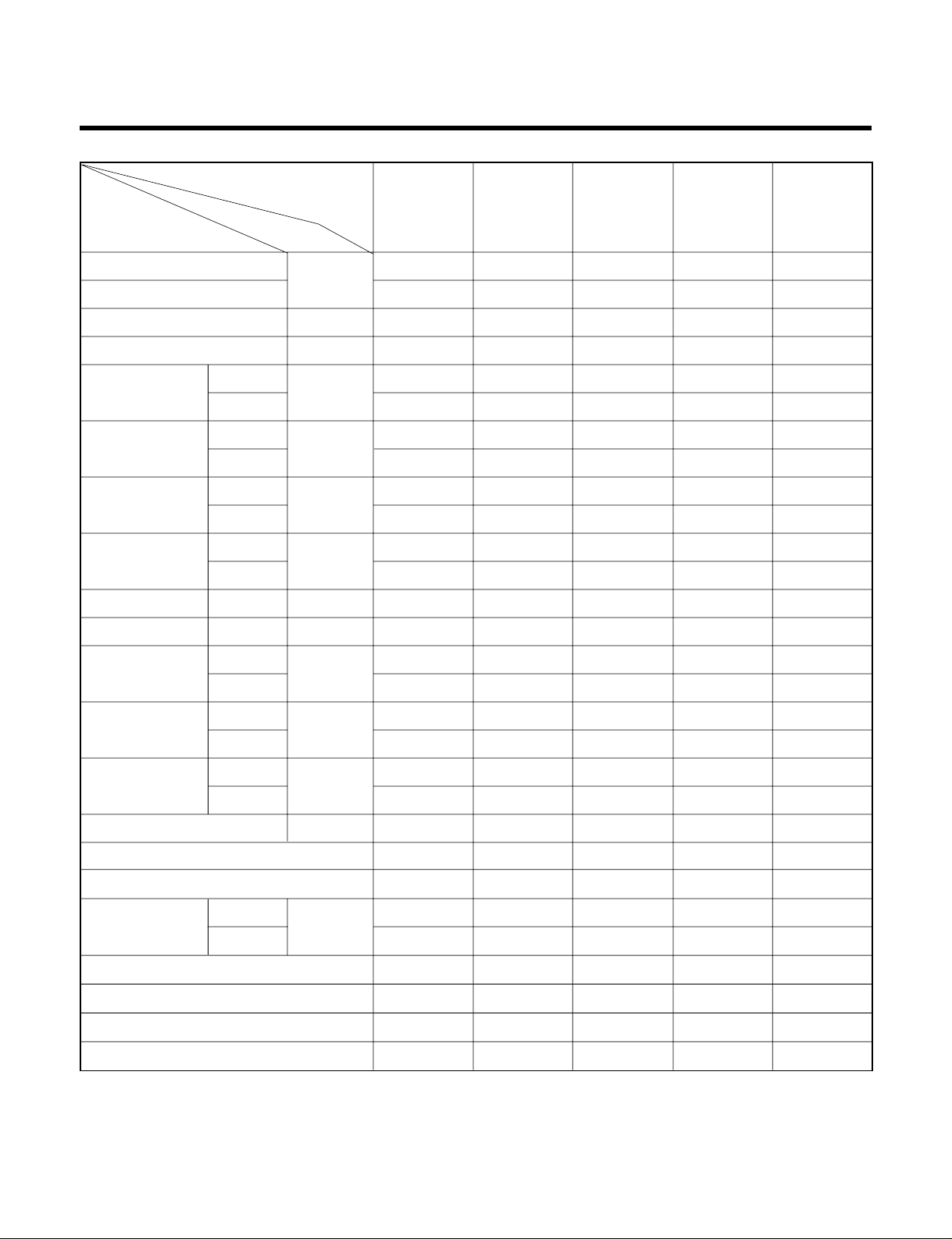
Code Type Code of Model Meaning
1,2 Type of Airconditioner A~Z LS: LG Split Type Airconditioner
3 Chassis A~Z Name of toll of Unit
Ex. LS-R ➔ S R Chassis
4,5 Capacity(Btu/h) 1~9 Cooling/Heating Capacity
Ex. "09" ➔ 9,000Btu/h
6 Electric Range 1~9 Electric Standard
1 ➔ 115V/60Hz 6 ➔ 220~240V/50Hz
2 ➔ 220V/60Hz 7 ➔ 110V, 50/60Hz
3 ➔ 208~230V/60Hz 8 ➔ 380~415V/50Hz
5 ➔ 200~220V/50Hz 9 ➔ 380~415V/60Hz
7 Serial No. 0~9
A~Z
8 Cooling/Heating A~Z
9 LG/OEM Brand A~Z L: LG Brand M: 1st OEM Brand
G: 2nd LG Brand N: 2nd OEM Brand
-
Basic A 0
Plasma Filter B 1
Auto Swing
+ Plasma Filter C 2
Telephone + LED Display D 3
Telephone + LCD Display E 4
Auto Swing
+ Plasma Filter + Telephone + LCD
F5
Low Ambient + Ambient/change G 6
Plasma Filter + Low Ambient + Ambient/change
H7
Internet J 8
Auto Swing + Plasma Filter + Oxygen Generator
K9
Auto Swing + Soft Start L Z
Auto Swing + Star Rating M Y
Auto Swing + Star Rating + Plasma Filter N X
Auto Swing + Soft Start + Star Rating P W
Auto Swing + Soft Start + Star Rating 4 + Plasma
QV
Auto Swing + Telephone + LCD R U
Auto Swing + Telephone + LCD + Soft Start
ST
C/O
C
A
D
G
K
H/P
H
B
E
J
L
E/H+C/O
X
5
7
-
-
E/H+H/P
Y
6
8
-
-
C/O
F
M
Q
-
-
H/P
R
P
S
-
-
C/O
V
W
1
3
H/P
N
Y
2
4
H/PTH/P
U
INDOOR
BASIC
BASIC
PLASMA
PLASMA
GOLD FIN
OUTDOOR
BASIC
GOLD FIN
GOLD FIN
BASIC
GOLD FIN
UNIT
R22
HFC R22+AC INV.
HFC+AC
INV.
HFC+DC
INV.
Page 4
Details of LG Model Name(2003)~
-4-
12 - 345678910
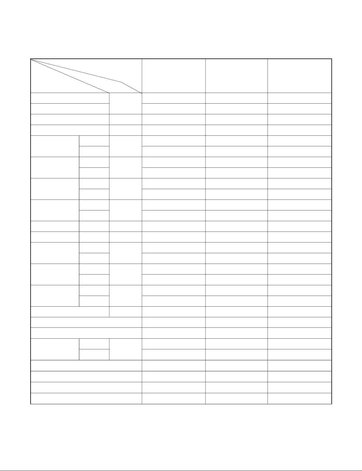
Code Type Code of Model Meaning
1 Producing Center, A~Z L: Chang-won R22 N: India
Refrigerant A: Chang-won R410A Z: Brazil
C: Chang-won R407C D: Indonesia
T: China M: Mexico
K: Turkey R22 V: Vietnam
E: Turkey R410A S: Out Sourcing
H: Thailand
2 Product Type A~Z S: Split Type Air Conditioner
3 Cooling/Heating/Inverter A~Z C: Cooling only
H: Heat pump
X: C/O + E/Heater
Z: H/P + E/Heater
V: AC Inverter C/O
N: AC Inverter H/P
Q: DC Inverter C/O
W: DC Inverter H/P
4, 5 Capacity 0~9 Cooling/Heating Capacity
Ex. "09" → 9,000 Btu/h
6 Electric Range 1~9 1: 115V/60Hz, A: 220V, 50Hz, 3Phase
A~Z 2: 220V/60Hz B: 208~230V, 60Hz, 3Phase
3: 208-230V/60Hz C: 575V, 50Hz, 3Phase
5: 200-220V/50Hz D: 440~460, 60Hz, 3Phase
6: 220-240V/50Hz E: 265V, 60Hz
7: 110V, 50/60Hz F: 200V, 50/60Hz
8: 380-415V/50Hz
9: 380-415V/60Hz
7 Chassis A~Z Name of Chassis of Unit
Ex. LSP → SP Chassis
8 Look A~Z Look,
Color (Artcool Model)
9 Function A~Z
10 Serial No. 1~9 LG Model De
* ARTCOOL COLOR
velopment Serial No.
Basic A
Basic+4Way B
Plasma Filter C
Plasma Filter+4 Way D
Tele+LCD E
Tele+LCD+Nano plasma+4Way F
Nano Plasma F+(A/changeove)+A/clean+Low A G
Nano Plasma F+(A/changeove)+A/clean+4way+Low A H
Tele+LED+4way I
Internet J
Plasma F+4Way+Oxy generator K
Nano Plasma F+(A/changeove)+A/clean L
Nano Plasma F+(A/changeove)+A/clean+4way M
Nano Plasma F+(A/changeove)+A/clean+PTC N
Nano Plasma F+(A/changeove)+Autoclean+4way+PTC P
Nano Plasma F+(A/changeove)+A/clean+4way+Low A+PTC Q
Negative ION+A/Clean R
(Nano)Plasma+Negative ION+A/Clean S
4way+(Nano)Plasma F+Negative ION+Healthy dehumidification+A/Clean
T
Nano Plasma F+4Way+(A/changeove)+A/clean+ U
R Mirror
W White
B Blue
D Wood
M Metal
C Cherry
Page 5
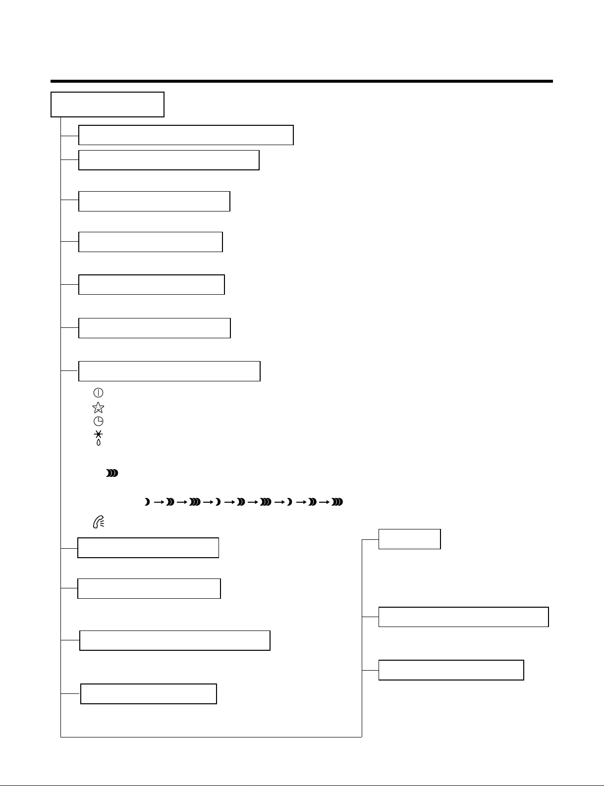
Functions
• Room temperature sensor. (THERMISTOR)
• Maintains the room temperature in accordance with the Setting Temp.
• Indoor fan is delayed for 5 sec at the starting.
• Restarting is inhibited for approx. 3 minutes.
• High, Med, Low, CHAOS, JET COOL
---
Lights up in operation
---
Lights up in Sleep Mode
---
Lights up in Timer Mode
---
Lights up in Defrost Mode (for Heating Model)
OUTDOOR---
Lights up in compressor operation (for Cooling Model)
---
The function illustrates its dynamic mode
by using a multiple lighting system.
()
---
Linghts up in Telephone Control operation.
• Intermittent operation of fan at low speed.
• The fan is switched to low(Cooling), med(Heating) speed.
• The unit will be stopped after 1, 2, 3, 4, 5, 6, 7 hours.
• The fan is switched to intermittent or irregular operation
•
The fan speed is automatically switched from high to low speed.
• The louver can be set at the desired position or swing
up and down automatically.
Indoor Unit
Operation ON/OFF by Remote controller
Sensing the Room Temperature
Room temperature control
Starting Current Control
Time Delay Safety Control
Indoor Fan Speed Control
Operation indication Lamps (LED)
Soft Dry Operation Mode
• The function will be operated while in any
operation mode with selecting the function.
• The function is to be stopped while it is
operating with selecting the function.
• Both the indoor and outdoor fan stops during defrosting.
• The indoor fan stops until the
evaporator pipe temperature will be reached
at 28°C.
Sleep Mode Auto Control
Natural Air Control by CHAOS Logic
Airflow Direction Control
-5-
Defrost(Deice) control (Heating)
Hot-start Control (Heating)
PLASMA
PLASMA
Page 6
-6-
Healthy Dehumidification Operation Mode.
( )
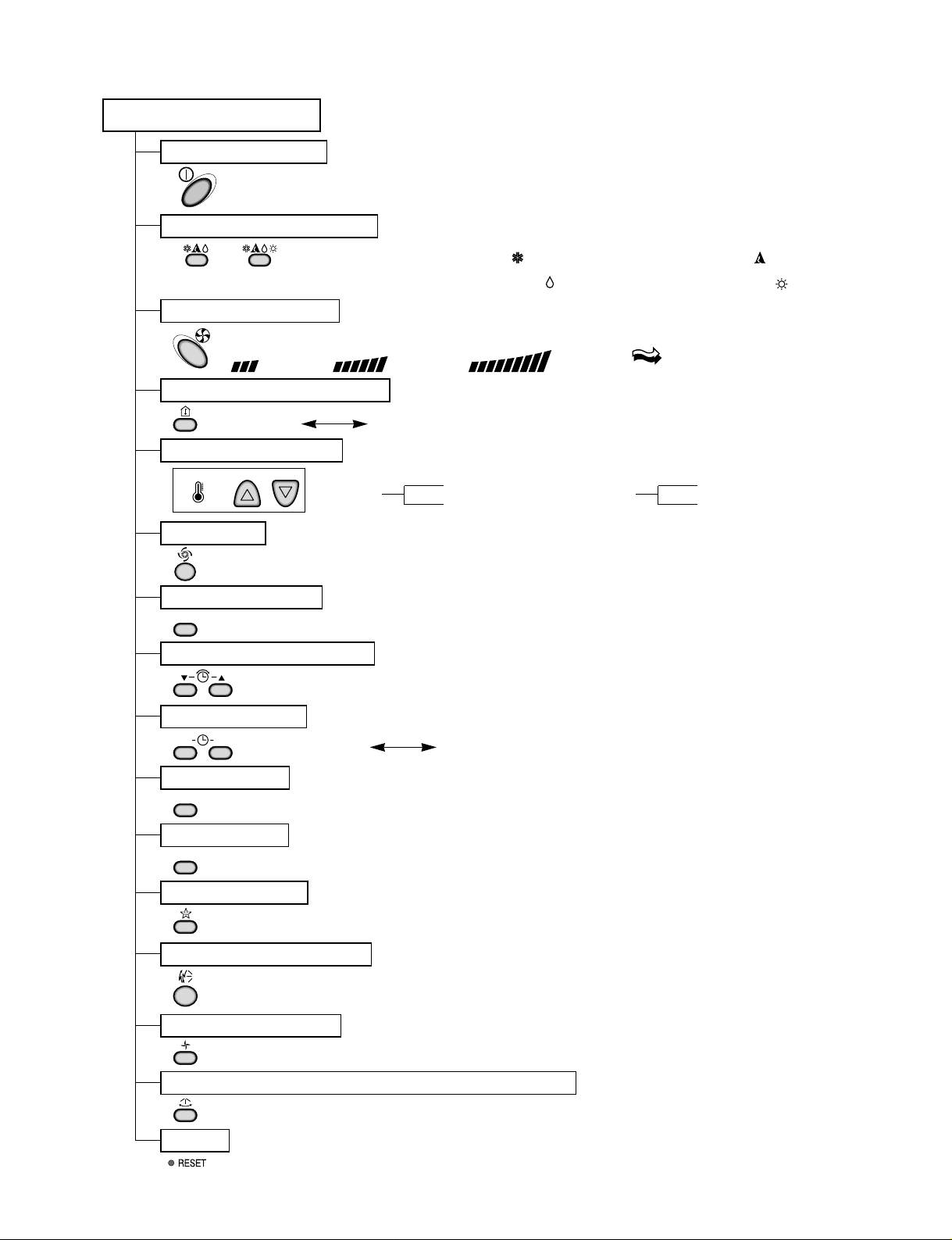
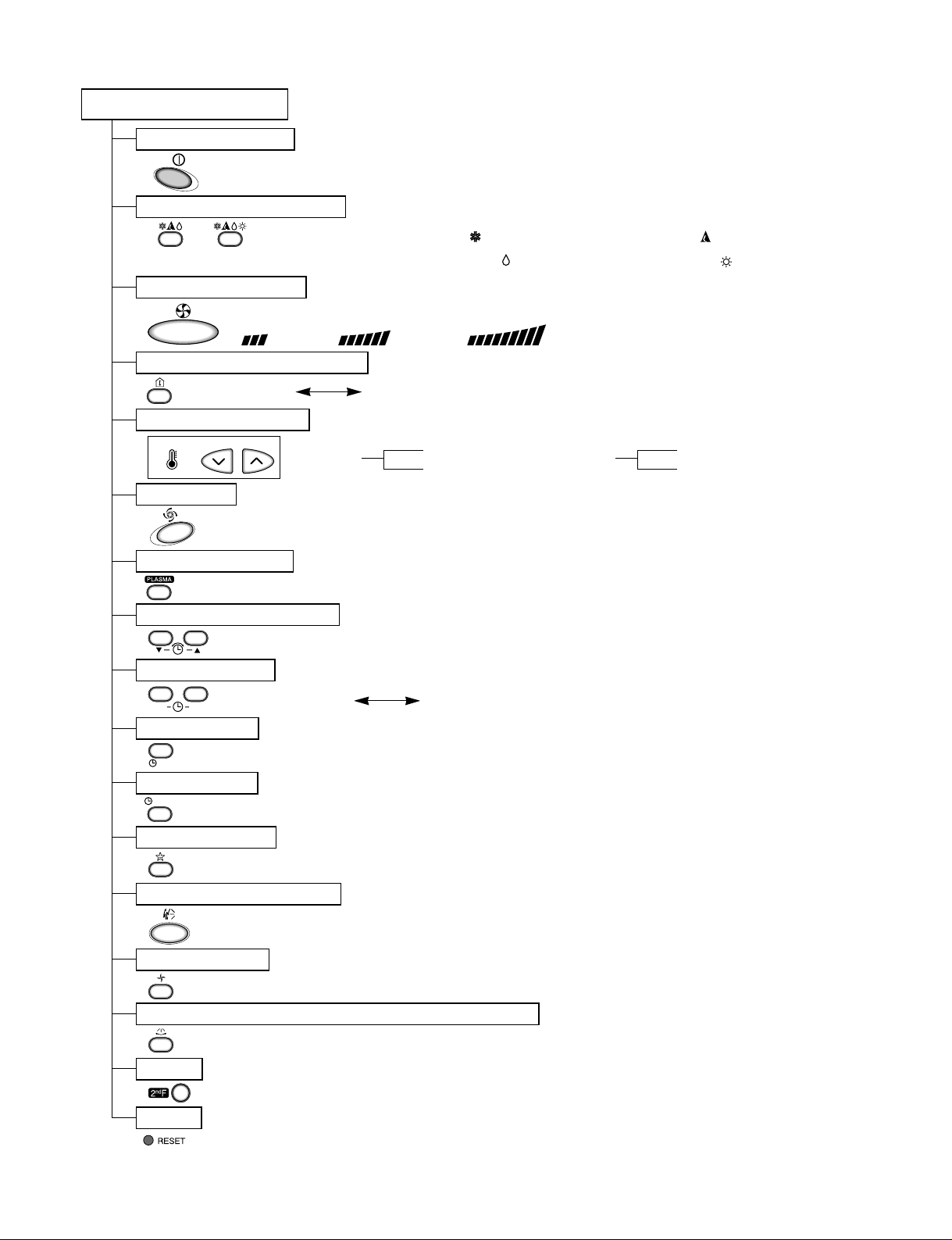
Remote Control
Operation ON/OFF
Reset
Operation Mode Selection
Temperature Setting
Timer Selection
Timer Setting
JET COOL
Timer Cancel
Sleep Operation
Airflow Direction Control
(Cooling
model only)
(Heating
model only)
TEMPERATURE
LOW HIGH
Cooling Operation Mode.( )
Heating Operation Mode.( )
Auto Operation Mode.( )
Fan Operation Mode
Horizontal Airflow Direction Control Button(Optional)
Room, Temperature Display
Setting the Time or Timer
PLASMA(Optional)
ON OFF
SET
PLASMA
CANCEL
Fan Speed Selection
(Low) (Med) (High) (CHAOS)
: (High:39°C Low:11°C)
: OFF, ON, OFF ON
: Cancel Sleep Mode, Timer ON or Timer OFF
: 1, 2, 3, 4, 5, 6, 7, Off Timer
: Fan Operates without cooling or heating.
Cooling
Down to 18°C
Up to 30°C
Heating
Down to 16°C
Up to 30°C
Page 7
-7-
Healthy Dehumidification Operation Mode.
( )
Remote Control
Operation ON/OFF
Reset
Operation Mode Selection
Temperature Setting
Timer Selection
Timer Setting
JET COOL
Timer Cancel
Sleep Operation
Airflow Direction Control
(Cooling
model only)
(Heating
model only)
TEMPERATURE
LOW HIGH
Cooling Operation Mode.( )
Heating Operation Mode.( )
Auto Operation Mode.( )
Air Circulation
Horizontal Airflow Direction Control Button(Optional)
Room, Temperature Checking
Setting the Time or Timer
PLASMA(Optional)
Fan Speed Selection
(Low) (Med) (High)
ON
OFF
CANCEL
SET
2nd F
: (High:39°C Low:11°C)
: OFF, ON, OFF ON
: Cancel Sleep Mode, Timer ON or Timer OFF
: 1, 2, 3, 4, 5, 6, 7, Off Timer
: Fan Operates without cooling or heating.
Cooling
Down to 18°C
Up to 30°C
Heating
Down to 16°C
Up to 30°C
Page 8
-8-
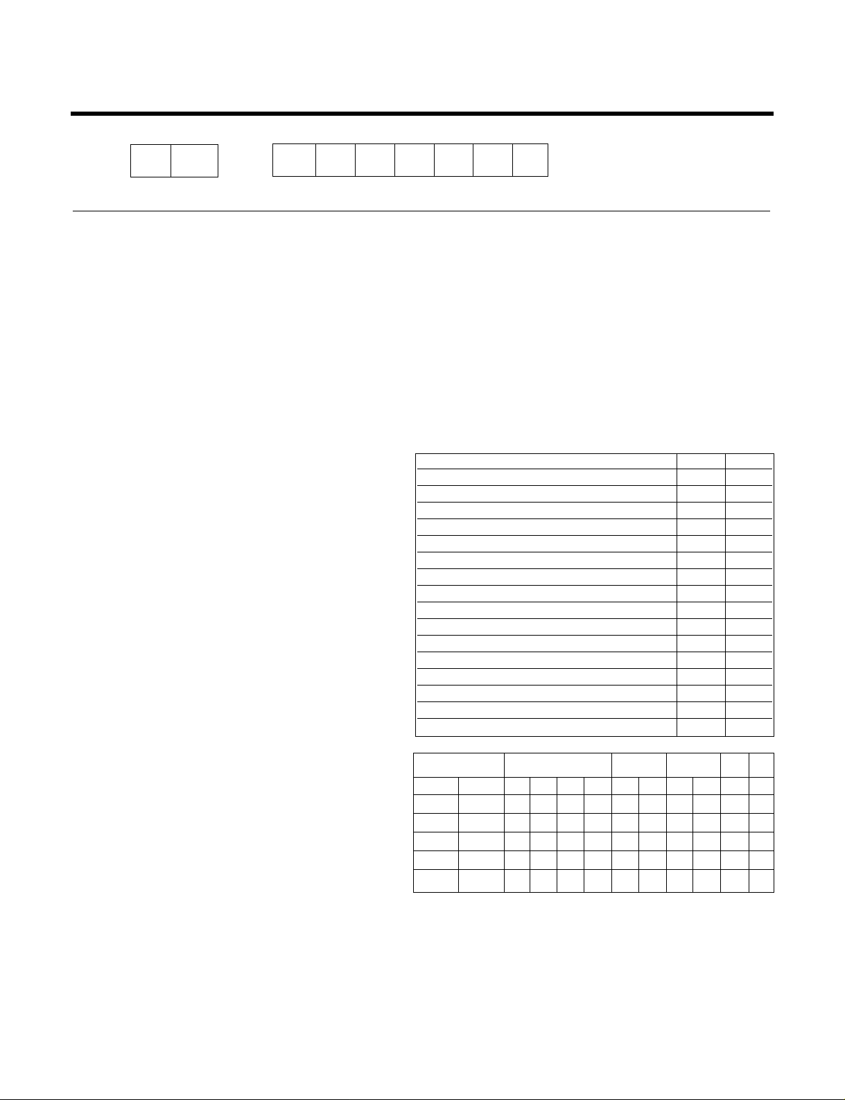
Product References
NOTE: Please refer to Label Quality on the product since this specification may be changed for improving
performance
Model Name
Item Unit
Cooling Capacity
Btu/h
Heating Capacity
Moisture Removal l/h
Power Source Ø,V,Hz
Cooling
W
Heating
Running Cooling
A
Current Heating
E.E.R. Cooling Btu/hW
C.O.P Heating
Refrigerant g
Airflow Direction Control (Up & Down)
Remocon Type
inch(mm)
Sleeping Operation
Drain Hose
Connecting Cable
Power Cord
LS-Q076BBG
LS-Q076BEL
LS-Q076ABL
LS-Q076ABG
LS-Q096BAG, LS-Q096ACG
LS-Q096ACL, LS-Q096AAL
LS-Q096ADG, LS-Q096ADL
LS-Q096BDG, LS-Q096BDL
LS-Q096AAG
LS-Q096BBG, LS-Q096BEL
LS-Q096AHG, LS-Q096ABL
LS-Q096ABG, LS-Q096AEL
LS-Q096ABM, LS-Q096AEM
LS-Q096BEG
LS-Q082BAG/BAM
LS-Q082AAL/ACG
LS-Q082ACL/ACM
LS-H096QNA0
7,000 9,000 9,000 8,000 8,500
7,300 - 9,300 - 8,750
1.0 1.0 1.0 1.0 1.0
1Ø, 220-240V, 50Hz 1Ø, 220-240V, 50Hz 1Ø, 220-240V, 50Hz 1Ø, 220V, 60Hz 1Ø, 220-240V, 50Hz
5.9 6 6 6 6
20 20 25 20 25
34 36 36 36 36
48 48 48 48 48
660 900 900 650 950
640 - 870 - 860
3.0 4.0 3.9 3.0 4.2
2.9 - 3.8 - 3.8
10.6 10 10 10 8.9
3.3 - 3.13 - 2.8
5 5.7 5.7 7.6 8.4
14 14.5 14.5 18.7 13.6
824 x 260 x 155 824 x 260 x 155 824 x 260 x 155 824 x 260 x 155 824 x 260 x 155
525 x 564 x 265 525 x 564 x 265 770 x 540 x 245 525 x 564 x 265 770 x 540 x 245
77777
23 23 33 23 23
610(R22) 530(R22) 640(R22) 630(R22) 680(R22)
OOOOO
L.C.D Wireless L.C.D Wireless L.C.D Wireless L.C.D Wireless L.C.D Wireless
1/4" (6.35) 1/4" (6.35) 1/4" (6.35) 1/4" (6.35) 1/4" (6.35)
3/8" (9.52) 3/8" (9.52) 3/8" (9.52) 3/8" (9.52) 3/8" (9.52)
OOOOO
OOOOO
0.75mm
2
0.75mm
2
0.75mm
2
0.75mm
2
0.75mm
2
0.75mm
2
0.75mm
2
0.75mm
2
0.75mm
2
0.75mm
2
Air Circulation
Noise Level
Input
m3/min
dB (A)±3
Indoor
Outdoor
Indoor
Outdoor
Indoor
Outdoor
Indoor
Outdoor
Indoor
Outdoor
Liquid
Gas
Service Valve
Motor Output
Dimensions
(WxHxD)
Net. Weight
W
mm
kg
Page 9
-9-
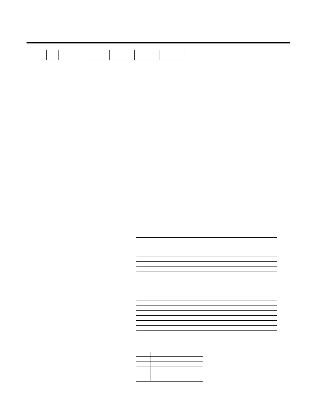
NOTE: Please refer to Label Quality on the product since this specification may be changed for improving
performance
Model Name
Item Unit
Cooling Capacity
Btu/h
Heating Capacity
Moisture Removal l/h
Power Source Ø, V, Hz
Cooling
W
Heating
Running Cooling
A
Current Heating
E.E.R. Cooling Btu/hW
C.O.P Heating
Refrigerant g
Airflow Direction Control (Up & Down)
Remocon Type
inch(mm)
Sleeping Operation
Drain Hose
Connecting Cable
Power Cord
LS-C096QLA0
QNA0/QGL0
LS-C082QMA0/QNA0 LS-H096QGL1
9,000 8,000 9,000
- - 9,300
1.0 1.0 1.0
1Ø, 220-240V, 50Hz 1Ø, 220V, 60Hz 1Ø, 220-240V, 50Hz
66 6
20 20 25
36 36 36
48 48 48
900 650 950
- - 860
4.0 3.0 4.2
- - 3.8
10 10 9.5
- - 2.8
5.7 7.6 8.4
14.5 18.7 13.6
824 x 260 x 155 824 x 260 x 155 824 x 260 x 155
525 x 564 x 265 525 x 564 x 265 770 x 540 x 245
77 7
23 23 23
530(R22) 630(R22) 680(R22)
OO O
L.C.D Wireless L.C.D Wireless L.C.D Wireless
1/4" (6.35) 1/4" (6.35) 1/4" (6.35)
3/8" (9.52) 3/8" (9.52) 3/8" (9.52)
OO O
OO O
0.75mm
2
0.75mm
2
0.75mm
2
0.75mm
2
0.75mm
2
0.75mm
2
Air Circulation
Noise Level
Input
m
3
/min
dB (A)±3
Indoor
Outdoor
Indoor
Outdoor
Indoor
Outdoor
Indoor
Outdoor
Indoor
Outdoor
Liquid
Gas
Service Valve
Motor Output
Dimensions
(W x H x D)
Net. Weight
W
mm
kg
Page 10
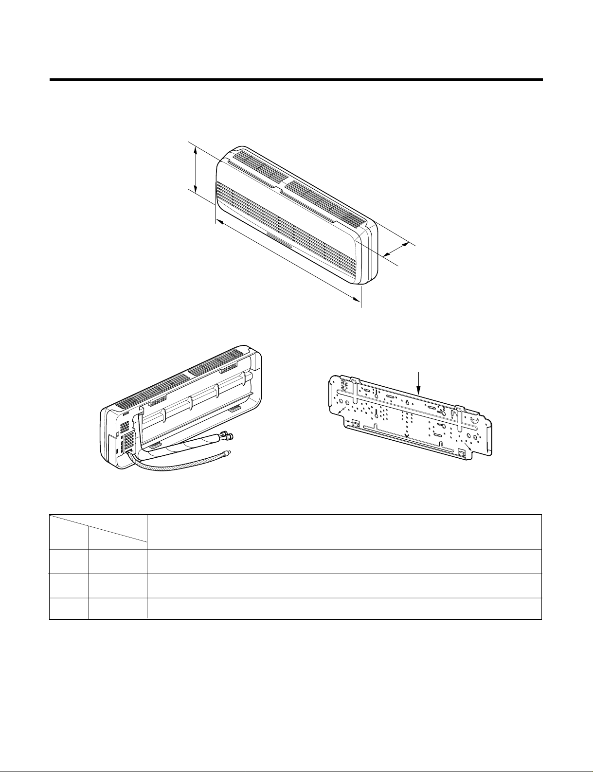
-10-
Installation plate
D
H
W
MODEL
DIM Unit
W mm 824
H mm 260
D mm 155
All Models
Dimensions
(1) Indoor Unit
Page 11
-11-
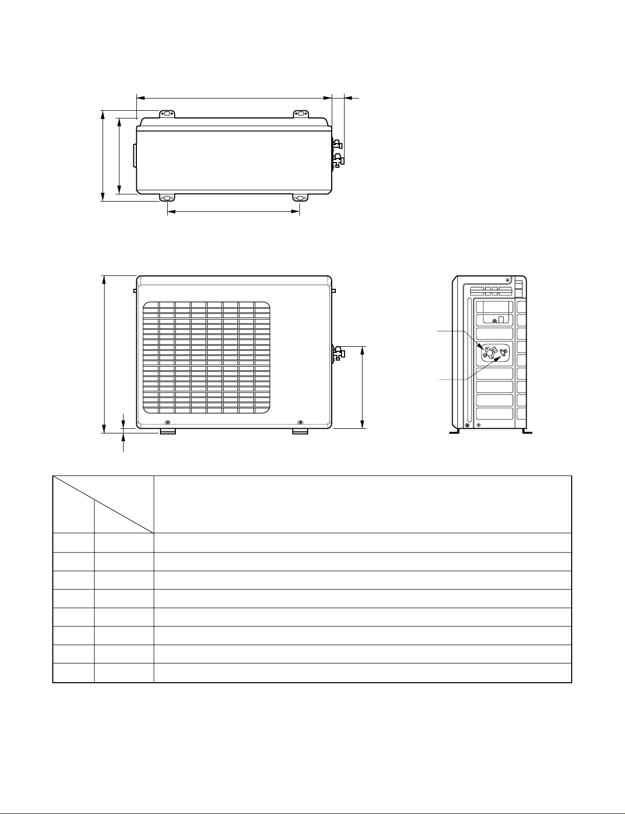
(2) Outdoor Unit
W
L2
L3
L1
D
H
L4
L5
Gas side
(3-way valve)
Liquid side
(2-way valve)
MODEL
DIM unit
W mm 564
H mm 525
D mm 265
L1 mm 294
L2 mm 66
L3 mm 374
L4 mm 17
L5 mm 270
7k Heat Pump, 8k Cooling, 9k Cooling
Page 12
-12-
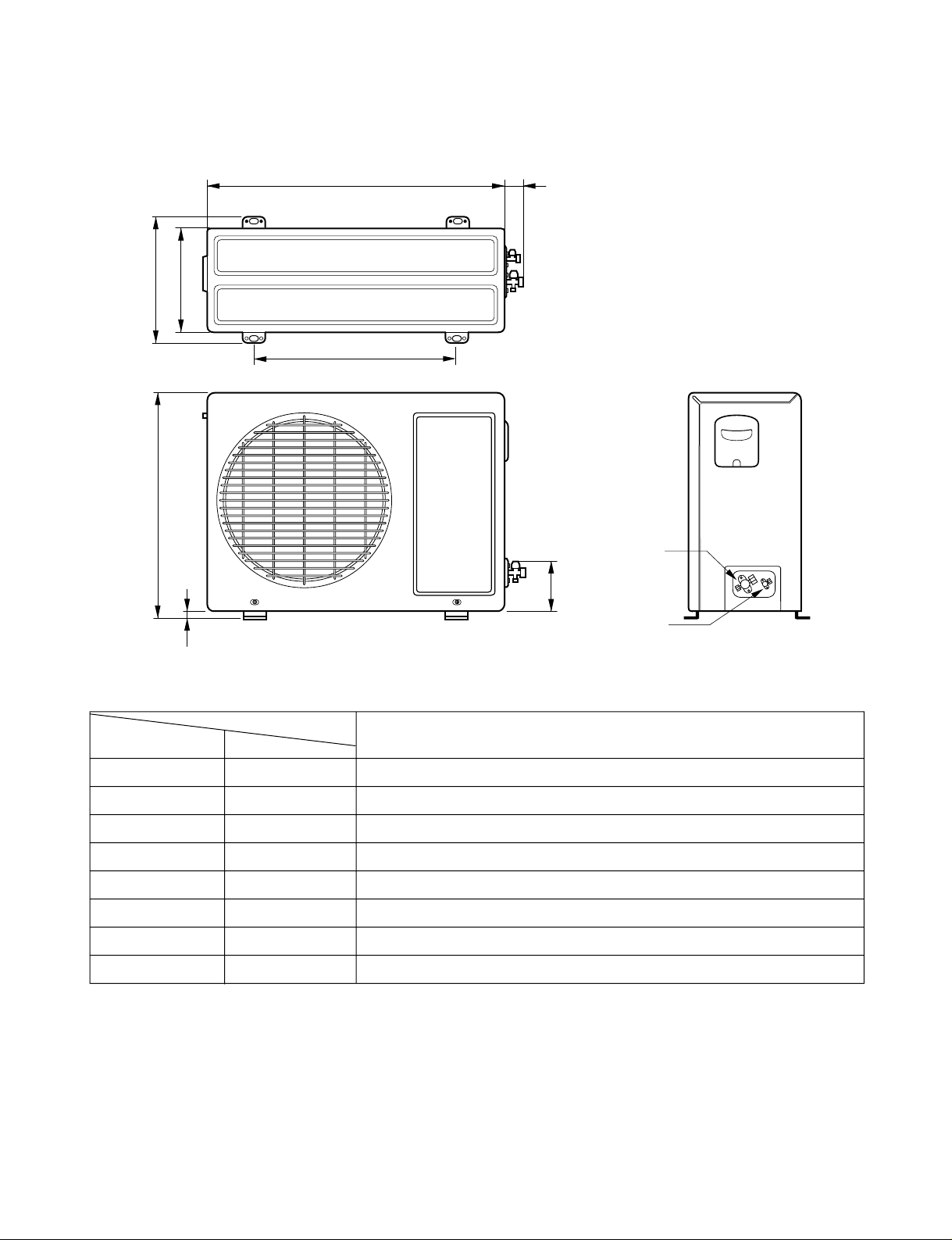
(3) Outdoor Unit
W
L2
L3
L1
D
H
L4
L5
Gas side
(3-way valve)
Liquid side
(2-way valve)
MODEL
9k Heat Pump
DIM unit
W mm 770
H mm 540
D mm 245
L1 mm 285
L2 mm 65
L3 mm 518
L4 mm 10
L5 mm 100
Page 13
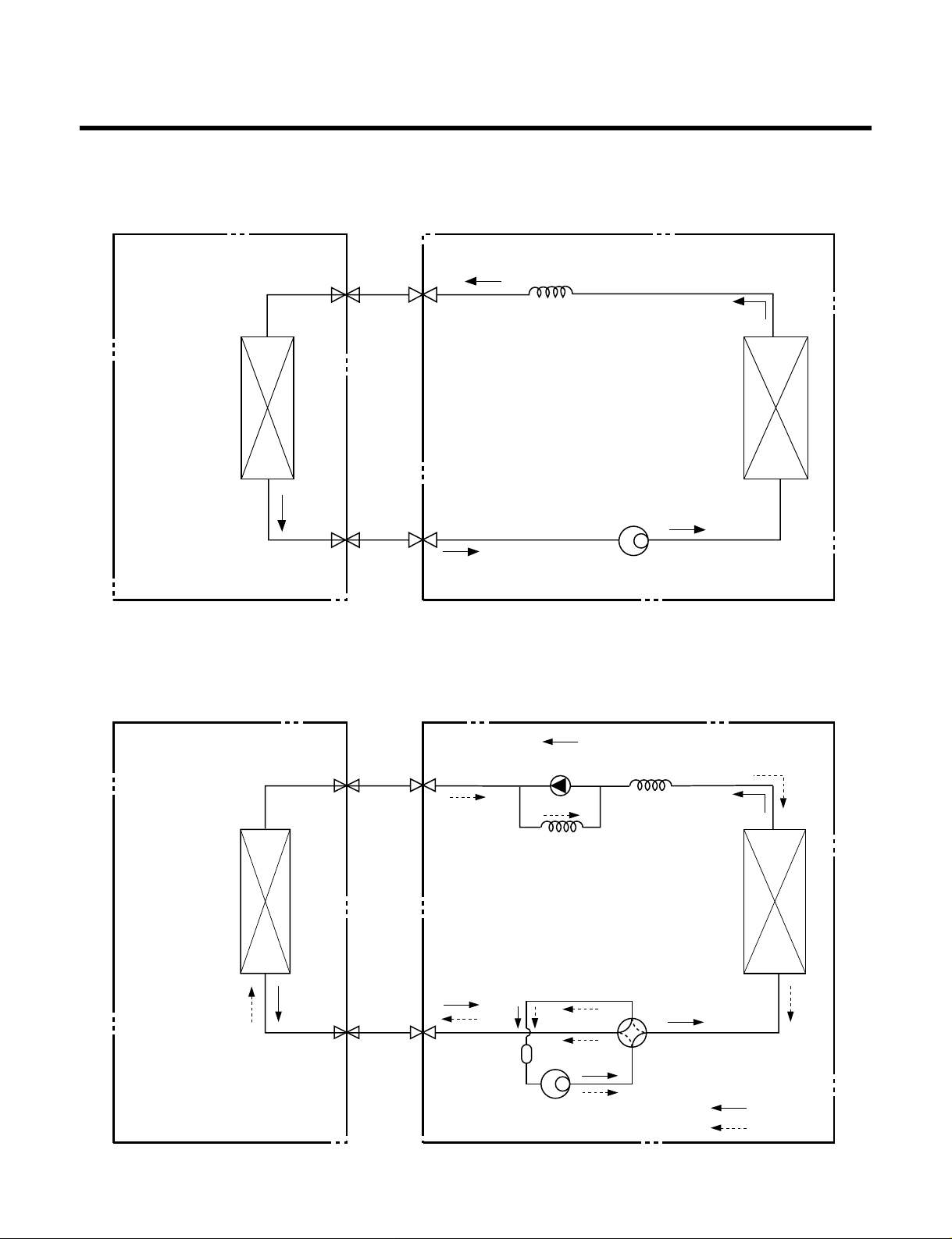
Refrigeration Cycle Diagram
-13-
INDOOR UNIT OUTDOOR UNIT
INDOOR UNIT OUTDOOR UNIT
HEAT
EXCHANGE
(EVAPORATOR)
HEAT
EXCHANGE
(EVAPORATOR)
HEAT
EXCHANGE
(CONDENSER)
HEAT
EXCHANGE
(CONDENSER)
COMPRESSOR
COMPRESSOR
ACCUMU
LATOR
GAS SIDE
GAS SIDE
VALVE
LIQUID SIDE
LIQUID SIDE
VALVE
CAPILLARY TUBE
CAPILLARY TUBE
CHECK VALVE
(Heating Model only)
COOLING
HEATING
REVERSING
VALVE
(Heating Model Only)
(1) Cooling Only Models
(2) Cooling & Heating Models
Page 14
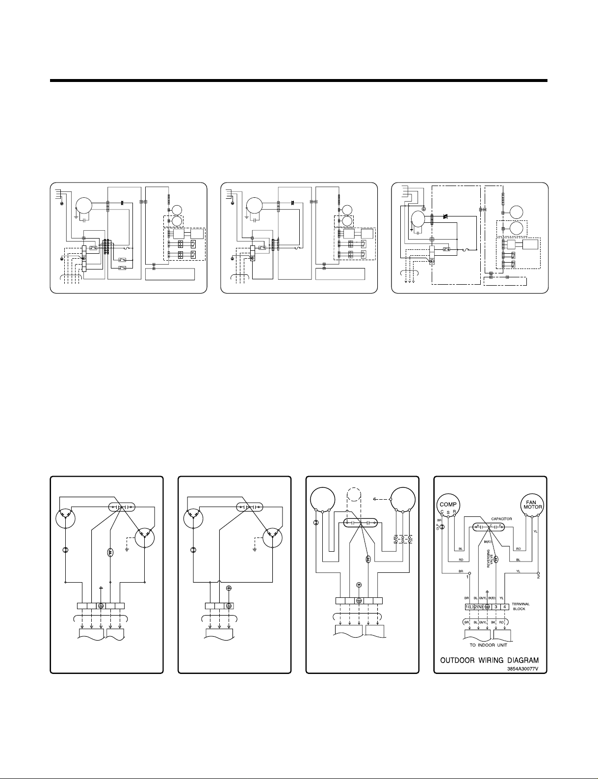
Wiring Diagram
-14-
(1) Indoor Unit
(2) Outdoor Unit
1.
LS-Q076ABL, LS-Q076BBG, LS-Q076BEL
LS-Q096ABL, LS-Q096ABG, LS-Q066AHG
LS-Q096AEL, LS-Q096BBG, LS-Q096ABM
LS-Q096AEM, LS-H096QNA0, LS-Q096BEG
2. LS-Q096AAG, LS-Q096AAL, LS-Q096ACG
LS-Q096ADL, LS-Q096ADG, LS-Q096BAG
LS-Q096BAG, LS-Q096BDG, LS-Q096BDL
LS-Q082BAM, LS-C096QGL0, LS-C096QLA0,
LS-C096QNA0, LS-H096QGL1
3. LS-Q082BAG, LS-Q096ACL, LS-Q082AAL
LS-Q082ACG, LS-Q082ACL, LS-Q082ACM
LS-C082QMA0, LS-C082QNA0
1. LS-Q076ABL, LS-Q076ABG,
LS-Q076BBG
LS-Q076BEL
2. LS-Q096AAG, LS-Q096AAL,
LS-Q096ACG, LS-Q096ADL,
LS-Q096ADG, LS-Q096ACL
LS-Q096BAG, LS-Q096BDG,
LS-Q096BDL LS-Q082BAG,
LS-Q096ABM, LS-Q082AAL
LS-Q082BAM, LS-Q082ACG,
LS-Q082ACL, LS-Q082ACM
LS-C082QMA0, LS-C082QNA0
LS-C096QCL0, LS-C096QLA0
LS-C096QNA0, LS-H096QGL1
3. LS-Q096ABL, LS-Q096AEL,
LS-Q096ABG, LS-Q096AHG,
LS-Q096BBG, LS-Q096BEL
LS-Q096ABM, LS-Q096AEM,
LS-Q096BEG
4. LS-H096QNA0, LS-H096QNA0
POWER
BR
(
BK/Plained
)
GN/YL
BRBLGN/YL
BL
(
WH/Ribbed
)
1(L) 2(N)
MOTOR
CN-MOTOR
CN-TAB1
CN-AC/DC
CN-AC/DC
CN-TH
THERMISTOR
STEP
MOTOR
STEP
MOTOR
H.V.
ASM
RD
AIR
CLEAN
(
PLASMA
)
SAFETY S/W1
SAFETY S/W2
BK
BK
BK
BK
BK
CN-U/D
CN-L/R
CN-DISP
DISPLAY PWB ASM
INDOOR WIRING DIAGRAM
3854A20142B
SW(FORCE)
T/BLOCK
TO OUTDOOR UNIT
TRIAC
AC PWB ASM DC PWB ASM
OR
BK
BR
4
RY-COMP
FUSE
250V T2A
3
YL
SH-CAPA
MOTOR
OR
RD
BK
BK BK
BK BK
BK BK
BK BK
POWER
BR(BK/Plained)
BL(WH/Ribbed)
BK
YL
SH-CAPA
T/BOARD
T-BLOCK
CN-MOTOR
THERMISTOR
STEP
MOTOR
CN-ACDC1
CN-ACDC2
CN-THCN-U/DCN-L/RCN-HVBCN-12V
CN-DISP
DISPLAY PWB ASM.
P/No : 3854A20238J
CN-CONT
TRIAC
AC PWB ASM. DC PWB ASM.
CN-TAB
RY-COMP
TO OUTDOOR UNIT
INDOOR WIRING DIAGRAM
43
1(L)
BR
BR
BL
GN/YL
2(N)
FUSE
250V T2A
STEP
MOTOR
H.V.
ASM.
S/W1
S/W2
AIR
CLEAN
(PLASMA)
GN/YL
GN/YL
MOTOR
OR
RD
BK
BK BK
BK BK
BK BK
BK BK
POWER
GN/YL
GN/YL
BR(BK/Plained)
BL(WH/Ribbed)
BK
YL
SH-CAPA
T/BOARD
T-BLOCK
RY-4WAY
RY-FAN
CN-MOTOR
THERMISTOR
STEP
MOTOR
CN-ACDC1
CN-ACDC2
CN-THCN-U/DCN-L/RCN-HVBCN-12V
CN-DISP
DISPLAY PWB ASM.
P/No : 3854A20238H
CN-CONT
TRIAC
AC PWB ASM. DC PWB ASM.
CN-TAB
RY-COMP
TO OUTDOOR UNIT
INDOOR WIRING DIAGRAM
43
1(L)
BR
BR
BL
BK
RD
GN/YL
2(N)
3 4
FUSE
250V T2A
STEP
MOTOR
H.V.
ASM.
S/W1
S/W2
AIR
CLEAN
(PLASMA)
TO INDOOR UNIT
BLACK GRAY
PILLAR
TERMINAL
BR
BR
YL
BK
OLP
123
COMP
RD
BK BLBL
FAN
MOTOR
REVERSING
VALVE
GN/YL
RD
BL
CAPACITOR
HC F
RCS
BR
BL BK RD
GN/YL
BR BL BK RD
GN/YL
1(L
) 2(N)
34
3854AR2262E
OUTDOOR WIRING DIAGRAM
TO INDOOR UNIT
BLACK
PILLAR
TERMINAL
BR
BR(YL)
OLP
1
COMP
RD
BL
BL
YL
FAN
MOTOR
GN/YL
RD
BL
CAPACITOR
HC F
RCS
BR
BL
GN/YL
BR BL
GN/YL
1(L
) 2(N)
3854AR2262F
OUTDOOR WIRING DIAGRAM
COMP
C
S
R
FAN
MOTOR
OLP
BR RD BL
BR BL
BK(RD)
YL
GN/YL
BR BL BK RD
GN/YL
BL BL
REVERSING
VALVE
RD BL YL
GN/YL
BK(RD)
CAPACITOR
RD
BL
YL
TO INDOOR UNIT
OUTDOOR WIRING DIAGRAM
3854A30077D
TERMINAL
BLOCK
HCF
PTC
1(L)2(N
)
34
Page 15

Operation Details
1. MAIN UNIT FUNCTION
• DISPLAY
1) C/O Model
Operation Indicator
• ON while in appliance operation, OFF while in appliance pause.
• Flashing while in disconnection or short in Thermistor. (3 sec off / 0.5 sec on)
Sleep Timer Indicator
• ON while in sleep timer mode, OFF when sleep timer cancel or appliance operation pause.
Timer Indicator
• ON while in timer mode (on/off), OFF when timer mode is completed or canceled.
Comp. Running Incidator
• While in appliance operation, ON while in outdoor unit compressor running, OFF while in compressor off.
2) H/P Model
Operation Indicator
• ON while in appliance operation, OFF while in appliance pause.
• Flashing while in disconnection or short in Thermistor. (3 sec off / 0.5 sec on)
Sleep Timer Indicator
• ON while in sleep timer mode, OFF when sleep timer cancel or appliance operation pause.
Timer Indicator
• ON while in timer mode (on/off), OFF when timer mode is completed or canceled.
Defrost Indicator
• OFF except when hot start during heating mode operation or while in defrost control.
■ Cooling Mode Operation
• When the intake air temperature reaches 0.5°C below the setting temp, the compressor and the outdoor fan
stop.
• When it reaches 0.5°C above the setting temp, they start to operate again.
Compressor ON Temp ➲ Setting Temp+0.5°C
Compressor OFF Temp ➲ Setting Temp-0.5°C
• While in compressor running, operating with the airflow speed set by the remote control. While in compressor
not running, operating with the low airflow speed regardless of the setting.
■ Healthy Dehumidification Mode
• When the dehumidification operation input by the remote control is received, the intake air temperature is
detected and the setting temp is automatically set according to the intake air temperature.
26°C ≤ Intake Air Temp ➲ 25°C
24°C ≤ Intake Intake Air Temp<26°C ➲ Intake Air Temp-1°C
18°C ≤ Intake Intake Air Temp<24°C ➲ Intake Air Temp-0.5°C
Intake Air Temp<18°C ➲ 18°C
-15-
Page 16

• While in compressor off, the indoor fan repeats low airflow speed and pause.
• While the intake air temp is between compressor on temp. and compressor off temp., 10-min dehumidifica-
tion operation and 4-min compressor off repeat.
Compressor ON Temp. ➲ Setting Temp+0.5°C
Compressor OFF Temp. ➲ Setting Temp-0.5°C
• In 10-min dehumidification operation, the indoor fan operates with the low airflow speed.
■ Heating Mode Operation
• When the intake air temp reaches +3°…above the setting temp, the compressor is turned off. When below
the setting temp, the compressor is turned on.
Compressor ON Temp. ➲ Setting Temp.
Compressor OFF Temp. ➲ Setting Temp.+3°C
• While in compressor on, the indoor fan is off when the indoor pipe temp. is below 20°C, when above 28°C,it
operates with the low or setting airflow speed. When the indoor pipe temp is between 20°C and 28°C, it operates with Super-Low(while in sleep mode, with the medium airflow speed).
• While in compressor off, the indoor fan is off when the indoor pipe temp is below 33°C, when above 35°C,it
operates with the low airflow speed.
• If overloaded while in heating mode operation, in order to prevent the compressor from OLP operation, the
outdoor fan is turned on/off according to the indoor pipe temp.
• While in defrost control, both of the indoor and outdoor fans are turned off.
■ Defrost Control
• While in heating mode operation in order to protect the evaporator pipe of the outdoor unit from freezing,
reversed to cooling cycle to defrost the evaporator pipe of the outdoor unit.
• After 40 min heating mode operation, at 4 min interval, whether to carry out defrost control or not and the time
of defrost control are determined according to the followingconditions.
1) While in heating mode operation, the maximum of the indoor pipe temperature is measured and it is com-
pared with the present indoor pipe temperature to get the difference of the indoor pipe temperatures (=the
maximum temperature of indoor pipe ? the present temperature of indoor pipe), according to which, whether
to carry out defrost control or not is determined.
2) According to the need of defrost control shown above and the elapsed time of heating mode operation at that
moment, the defrost control time is determined.
3) When the determined time of defrost control is below 7 min, heating mode operation continues without carry-
ing out defrost control. According to the procedure stated above, the determination is made again. When the
defrost control time is 7 min or longer, defrost control is then carried out.
• While in defrost control, the minimum temp of the indoor pipe is measured and it is compared with the present
temp of the indoor pipe to get the difference of the indoor pipe temperatures (=the present temperature of the
indoor pipe ? the minimum temperature of the indoor pipe). When the difference is 5°C or higher, defrost control is completed and heating mode operation is carried out.
• While in defrost control, if the defrost time determined before the start of defrost control is completed, defrost
control stops and heating mode operation is carried out regardless of the above condition.
• When the indoor pipe temp is 42°C or above, defrost control is not carried out even if the condition is one of
the defrost conditions above.
• While in defrost control, the compressor is on and the indoor fan, the outdoor fan, and the 4 way valve are off.
-16-
Page 17

-17-
■ Fuzzy Operation (C/O Model)
• According to the temperature set by Fuzzy rule, when the intake air temp is 0.5°C or more below the setting
temp, the compressor is turned off. When 0.5°C or more above the setting temp, the compressor is turned on.
Compressor ON Temp ➲ Setting Temp + 0.5°C
Compressor OFF Temp ➲ Setting Temp + 0.5°C
• At the beginning of Fuzzy mode operation, the setting temperature is automatically selected according to the
intake air temp at that time.
26°C ≤ Intake Air Temp ➲ 25°C
24°C ≤ Intake Air Temp < 26°C ➲ Intake Air Temp + 1°C
22°C ≤ Intake Air Temp < 24°C ➲ Intake Air Temp + 0.5°C
18°C ≤ Intake Air Temp < 22°C ➲ Intake Air Temp
Intake Air Temp<18°C ➲ 18°C
• When the Fuzzy key (Temperature Control key) is input after the initial setting temperature is selected, the
Fuzzy key value and the intake air temperature at that time are compared to select the setting temperature
automatically according to the Fuzzy rule.
• While in Fuzzy operation, the airflow speed of the indoor fan is automatically selected according to the
temperature.
■ Fuzzy Operation (H/P Model)
• When any of operation mode is not selected like the moment of the power on or when 3 hrs has passed since
the operation off, the operation mode is selected.
• When determining the operation mode, the compressor, the outdoor fan, and the 4 way valve are off and only
the indoor fan is operated for 15 seconds. Then an operation mode is selected according to the intake air
temp at that moment as follows.
24°C ≤ Inatake Air Temp ➲ Fuzzy Operation for Cooling
21°C ≤ Inatake Air Temp<24°C ➲ Fuzzy Operation for Dehumidification
Inatake Air Temp<21°C ➲ Fuzzy Operation for Heating
• If any of the operation modes among cooling / dehumidification / heating mode operations is carried out for 10
sec or longer before Fuzzy operation, the mode before Fuzzy operation is operated.
1) Fuzzy Operation for Cooling
• According to the setting temperature selected by Fuzzy rule, when the intake air temp is 0.5°C or more below
the setting temp, the compressor is turned off. When 0.5°C or more above the setting temp, the compressor
is turned on.
Compressor ON Temp ➲ Setting Temp +0.5°C
Compressor OFF Temp ➲ Setting Temp + 0.5°C
• At the beginning of Fuzzy mode operation, the setting temperature is automatically selected according to the
intake air temp at that time.
26°C≤ Intake Air Temp ➲ 25°C
24°C≤ Intake Air Temp<26°C ➲ Intake Air Temp + 1°C
22°C≤ Intake Air Temp<24°C ➲ Intake Air Temp + 0.5°C
18°C≤ Intake Air Temp<22°C ➲ Intake Air Temp
Intake Air Temp<18°C ➲ 18°C
• When the Fuzzy key (Temperature Control key) is input after the initial setting temperature is selected, the
Fuzzy key value and the intake air temperature at that time are compared to select the setting temperature
automatically according to the Fuzzy rule.
• While in Fuzzy operation, the airflow speed of the indoor fan is automatically selected according to the temperature.
Page 18

-18-
2) Fuzzy Operation for Dehumidification
• According to the setting temperature selected by Fuzzy rule, when the intake air temp is 0.5°C or more below
the setting temp, the compressor is turned off. When 0.5°C or more above the setting temp, the compressor
is turned on.
Compressor ON Temp ➲ Setting Temp + 0.5°C
Compressor OFF Temp ➲ Setting Temp+0.5°C
• At the beginning of Fuzzy mode operation, the setting temperature is automatically selected according to the
intake air temp at that time.
26°C ≤ Intake Air Temp ➲ 25°C
24°C ≤ Intake Air Temp<26°C ➲ Intake Air Temp+1°C
22°C ≤ Intake Air Temp<24°C ➲ Intake Air Temp+0.5°C
18°C ≤ Intake Air Temp<22°C ➲ Intake Air Temp
Intake Air Temp<18°C ➲ 18°C
• When the Fuzzy key (Temperature Control key) is input after the initial setting temperature is selected, the
Fuzzy key value and the intake air temperature at that time are compared to select the setting temperature
automatically according to the Fuzzy rule.
• While in Fuzzy operation, the airflow speed of the indoor fan repeats the low airflow speed or pause as in
dehumidification operation.
3) Fuzzy Operation for Heating
• According to the setting temperature selected by Fuzzy rule, when the intake air temp is 3°Cormoreabove
the setting temp, the compressor is turned off. When below the setting temp, the compressor is turned on.
Compressor ON Temp ➲ Setting Temp
Compressor OFF Temp ➲ Setting Temp + 3°C
• At the beginning of Fuzzy mode operation, the setting temperature is automatically selected according to the
intake air temp at that time.
20°C≤Intake Air Temp ➲ Intake Air Temp + 0.5°C
Intake Air Temp<20°C ➲ 20°C
• When the Fuzzy key (Temperature Control key) is input after the initial setting temperature is selected, the
Fuzzy key value and the intake air temperature at that time are compared to select the setting temperature
automatically according to the Fuzzy rule.
• While in Fuzzy operation, the airflow speed of the indoor fan is set to the high or the medium according to the
intake air temperature and the setting temperature.
■ Airflow Speed Selection
• The airflow speed of the indoor fan is set to high, medium, low, or chaos (auto) by the input of the airflow
speed selection key on the remote control.
■ On-Timer Operation
• When the set time is reached after the time is input by the remote control, the appliance starts to operate.
• The timer LED is on when the on-timer is input. It is off when the time set by the timer is reached.
• If the appliance is operating at the time set by the timer, the operation continues.
Page 19
-19-
■ Off-Timer Operation
• When the set time is reached after the time is input by the remote control, the appliance stops operating.
• The timer LED is on when the off-timer is input. It is off when the time set by the timer is reached.
• If the appliance is on pause at the time set by the timer, the pause continues.
■ Off-Timer ↔ On-Timer Operation
• When the set time is reached after the on/off time is input by the remote control, the on/off-timer operation is
carried out according to the set time.
■ Sleep Timer Operation
• When the sleep time is reached after <1,2,3,4,5,6,7,0(cancel) hr> is input by the remote control while in appliance operation, the operation of the appliance stops.
• While the appliance is on pause, the sleep timer mode cannot be input.
• While in cooling mode operation, 30 min later since the start of the sleep timer, the setting temperature
increases by 1°C. After another 30 min elapse, it increases by 1°C again.
• When the sleep timer mode is input while in cooling cycle mode, the airflow speed of the indoor fan is set to the
low.
• When the sleep timer mode is input while in heating cycle mode, the airflow speed of the indoor fan is set to
the medium.
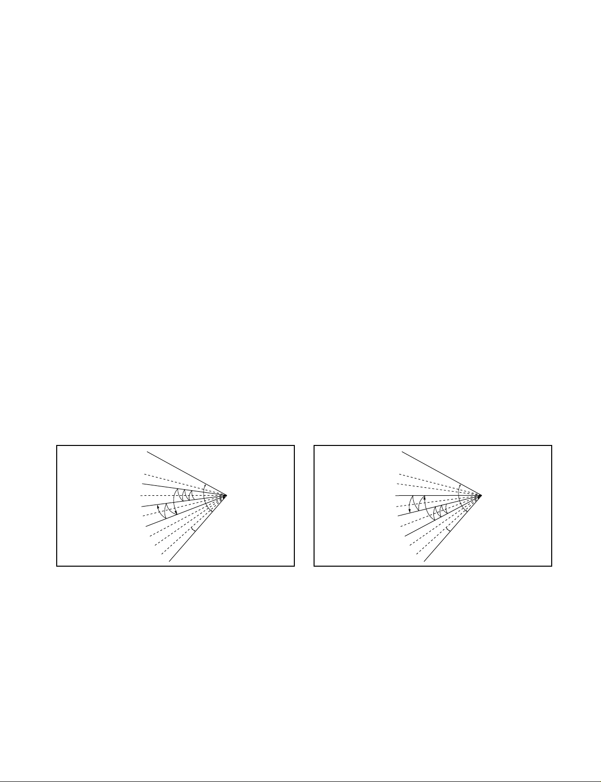
■ Chaos Swing Mode
• By the Chaos Swing key input, the upper/lower vane automatically operates with the Chaos Swing or they are
fixed to the desired direction.
• While in Chaos Swing mode, the angles of cooling and heating cycle operations are different.
■ Chaos Natural Wind Mode
• When the Chaos Natural Wind mode is selected and then operated, the high, medium, or low speed of the airflow mode is operated for 2~15 sec. randomly by the Chaos Simulation.
CLOSED
OPEN
< Cooling Mode >
7°
CLOSED
OPEN
< Heating Mode >
7°
Page 20
-20-
■ Jet Cool Mode Operation (C/O Model)
• If the Jet Cool key is input at any operation mode while in appliance operation, the Jet Cool mode operates.
• In the Jet Cool mode, the indoor fan is operated at super-high speed for 30 min at cooling mode operation.
• In the Jet Cool mode operation, the room temperature is controlled to the setting temperature, 18°C
• When the sleep timer mode is input while in the Jet Cool mode operation, the Jet Cool mode has the priority.
• When the Jet Cool key is input, the upper/lower vanes are reset to those of the initial cooling mode and then
operated in order that the air outflow could reach further.
■ Jet Cool Mode Operation (H/P Model)
• While in heating mode or Fuzzy operation, the Jet Cool key cannot be input. When it is input while in the other
mode operation (cooling, dehumidification, ventilation), the Jet Cool mode is operated.
• In the Jet Cool mode, the indoor fan is operated at super-high speed for 30 min at cooling mode operation.
• In the Jet Cool mode operation, the room temperature is controlled to the setting temperature, 18
°C.
• When the sleep timer mode is input while in the Jet Cool mode operation, the Jet Cool mode has the priority.
• When the Jet Cool key is input, the upper/lower vanes are reset to those of the initial cooling mode and then
operated in order that the air outflow could reach further.
■ Forced Operation
• Operation procedures when the remote control can't be used.
• The operation will be started if the power button is pressed.
• If you want to stop operation, re-press the button.
• While in forced operation, the key input by the remote control has no effect and the buzzer sounds 10 times to
indicate the forced operation.
■ Test operation
•
During the TEST OPERATION, the unit operates in cooling mode at high speed fan, regardless of room temperature and resets in 18±1 minutes.
•
During test operation, if remote controller signal is received, the unit operates as remote controller sets.
If you want to use this operation, open the front panel upward and Press the power button let it be pressed for
about 3 seconds.
•
If you want to stop the operation, re-press the button.
■ Auto restart
•
In case the power comes on again after a power failure, Auto Restarting Operation is the function to operate
procedures automatically to the previous operating conditions.
■ Air Cleaner Operation
•
When an air cleaner function is selected during Air Conditioner operation
- Plasma air cleaner function will be operated while in any operation mode with selecting the function.
- The function is to be stopped while it is operating with selecting the function.
•
When an air cleaner function is selected during operation off
- The function will be only operated.
•
When inlet grille of air conditioner is opened during plasma operation, High Voltage Generator(H.V.B) is to be
stopped. When inlet grille of air conditioner is closed during plasma operation, High Voltage Generator(H.V.B)
will be operated again.
Heat pump Model
Cooling Model
Room Temp.≥ 24°C21°C ≤ Room Temp. < 24°C Room Temp. < 21°C
Operating mode Cooling Cooling Healthy Dehumidification Heating
Indoor FANSpeed
High High High High
Setting Temperature
22°C22°C23°C24°C
Page 21

-21-
■ Remote Control Operation Mode
• When the remote control is selected by the slide switch on the main unit, the appliance operates according to
the input by the remote control.
■ Protection of the evaporator pipe from frosting
• If the indoor pipe temp is below 0°C in 7 min. after the compressor operates without any pause while in cooling cycle operation mode, the compressor and the outdoor fan are turned off in order to protect the indoor
evaporator pipe from frosting.
• When the indoor pipe temp is 7°C or higher after 3 min. pause of the compressor, the compressor and the
outdoor fanis turned on according to the condition of the room temperature.
■ Buzzer Sounding Operation
• When the appliance-operation key is input by the remote control, the short "beep-beep-" sounds.
• When the appliance-pause key is input by the remote control, the long "beep—" sounds.
• When a key is input by the remote control while the slide switch on the main unit of the appliance is on the
forced operation position, the error sound "beep-beep-beep-beep-beep-" is made 10 times to indicate that the
remote control signal cannot be received.
Page 22
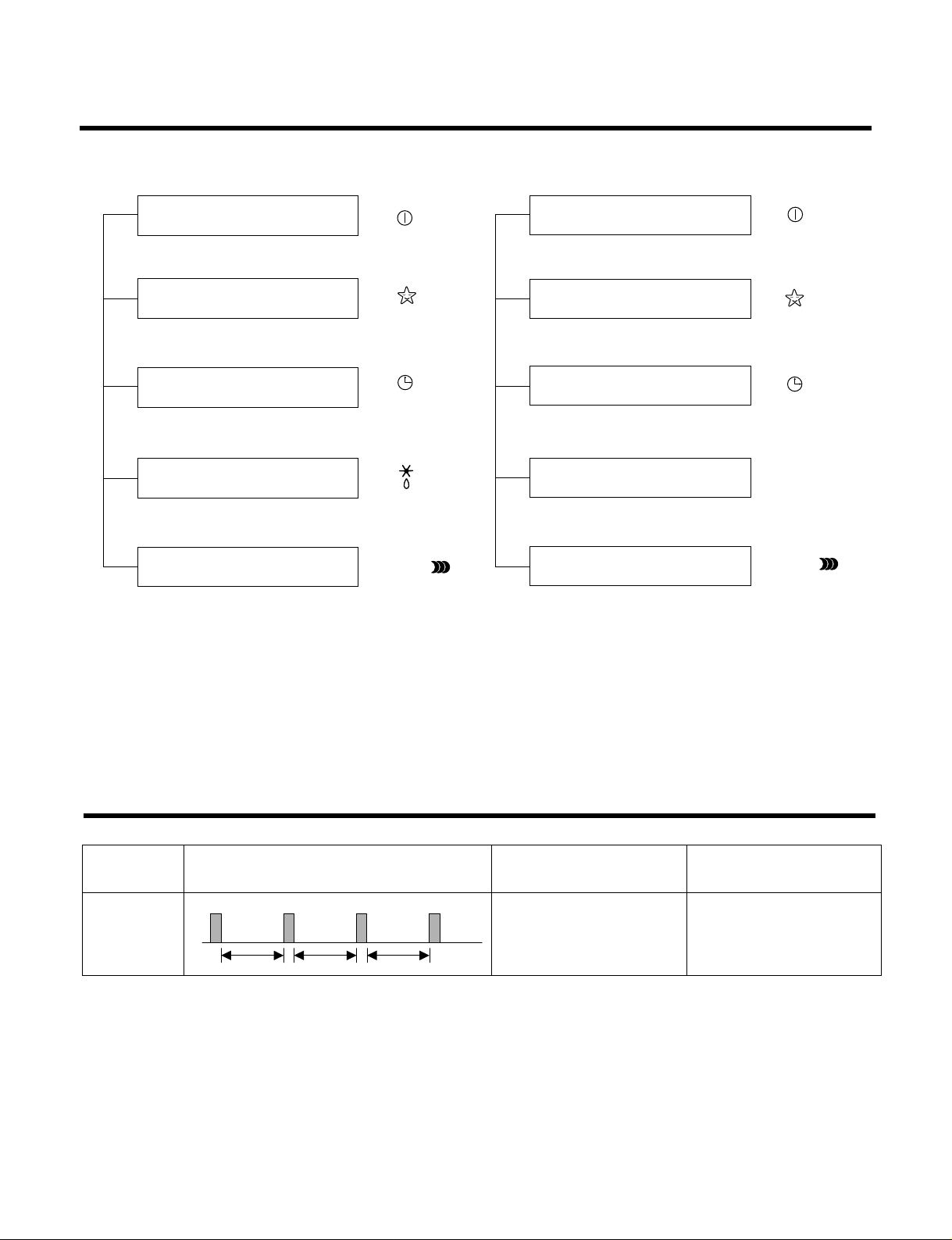
Display Function
-22-
Self-diagnosis Function
3sec 3sec 3sec
(once)
Error
Code
1
Error Display LED
(Indoor body operation LED)
Error contents
• Indoor room temperature
thermistor open/short
• Indoor pipe temperature
thermistor open/short.
• Indoor Thermistor
assembly check
SVC check point
1. Heating Model 2. Cooling Model
• Cooling, Soft Dry, Fan, Heating • Cooling, Soft Dry, Fan
• Sleep Mode • Sleep Mode
• Timer Mode • Timer Mode
• Hot-start, Defrost
• PLASMA Mode • PLASMA Mode
Operation Indicator
Timer Indicator
Sleep Timer Indicator
Defrost Indicator
PLASMA Indicator
Operation Indicator
Timer Indicator
Sleep Timer Indicator
Compressor Indicator
PLASMA Indicator
OUTDOOR
PLASMA
PLASMA
Page 23
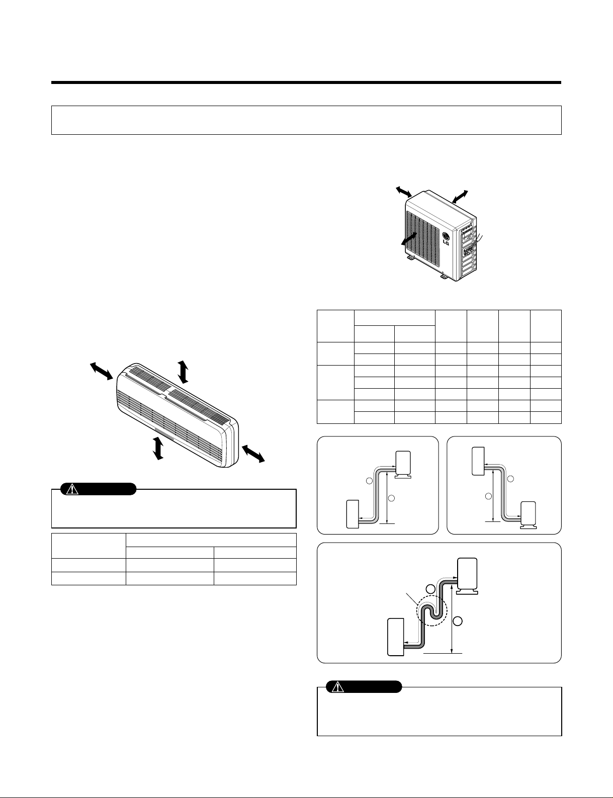
1) Selection of the best location
1. Indoor unit
• Do not have any heat or steam near the unit.
• Select a place where there are no obstacles in front of
the unit.
• Make sure that condensation drainage can be conveniently routed away.
Do not install near a doorway.
• Ensure that the space around the left and right of the
unit is more than "A". The unit should be installed as
high on the wall as possible, allowing a minimum of
"B" from ceiling.
• Use a stud finder to locate studs to prevent unnecessary damage to the wall.
2. Outdoor unit
• If an awning is built over the unit to prevent direct sunlight or rain exposure, make sure that heat radiation
from the condenser is not restricted.
• Ensure that the space around the back and sides is
more than 10cm. The front of the unit should have
more than 70cm of space.
• Do not place animals and plants in the path of the
warm air.
• Take the air conditioner weight into account and select
a place where noise and vibration are minimum.
• Select a place so that the warm air and noise from the
air conditioner do not disturb neighbors.
2) Piping length and elevation
Installation
1. Installation of indoor, Outdoor unit
-23-
More than "A"
More than "B"
More than 2.3m
More than "B"
More than 10 cm
More than 10 cm
More than 70 cm
Install the indoor unit on the wall where the height
from the floors more than 2.3 meters.
CAUTION
• Capacity is based on standard length and maximum
allowance length is on the basis of reliability.
• Oil trap should be installed every 5~7 meters.
CAUTION
Grade
Clearance(cm)
AB
7K~28K 10 5
30K~38K 30 12
Pipe Size
Capacity
(Btu/h)
GAS LIQUID
Max.
Length
A (m)
Additional
Refrigerant
(g/m)
Max.
Elevation
B (m)
Standard
Length
(m)
7k~14k
3/8"(Ø9.52) 1/4"(Ø6.35) 4or 7.5 7 15 20
1/2"(Ø12.7) 1/4"(Ø6.35) 4or 7.5 7 15 20
1/2"(Ø12.7) 1/4"(Ø6.35) 4or 7.5 15 30 20
18k~28k 5/8"(Ø15.88) 1/4"(Ø6.35) 4 or 7.5 15 30 20
5/8"(Ø15.88) 3/8"(Ø9.52) 4or 7.5 15 30 30
30k~38k
5/8"(Ø15.88) 3/8"(Ø9.52) 7.5 15 30 30
3/4"(Ø19.05) 3/8"(Ø9.52) 7.5 15 30 50
If case more than 5m
Outdoor unit
Indoor unit
A
B
Outdoor unit
Indoor unit
A
B
A
Oil trap
Outdoor unit
Indoor unit
B
I
Page 24

-24-
3) How to fix installation plate
The wall you select should be strong and solid enough
to prevent vibration
1. Mount the installation plate on the wall with four
type A screws. If mounting the unit on a concrete
wall, use anchor bolts.
• Mount the installation plate horizontally by aligning
thecenterlineusingalevel.
2. Measure the wall and mark the centerline. It is
also important to use caution concerning the
location of the installation plate-routing of the
wiring to power outlets is through the walls typically. Drilling the hole through the wall for piping
connections must be done safely.
4) Drill a hole in the wall
• Drill the piping hole with a ø70mm hole core drill. Drill
the piping hole at either the right or the left with the
hole slightly slanted to the outdoor side.
Installation Plate
Type "A" screw
5-7mm
(3/16"~5/16")
Indoor
WALL
Outdoor
Installation plate
Ø70mm
Left rear piping Right rear piping
C
D
B
A
Ø70mm
Ø70mm
Left rear piping
Right rear piping
CE A
B
D
Installation plateInstallation plate
ABCD
SJ 90 20 80 20
SL, SK 45 40 80 20
SQ 75 12 80 12
SR 0 40 20 40
ST 105 0 210 0
CHASSIS
(Grade)
Distance (mm)
ABCDE
SM 180 115 - 115 50
SN 180 115 195 115 -
CHASSIS
(Grade)
Distance (mm)
Page 25
-25-
2. Flaring Work and Connection of Piping
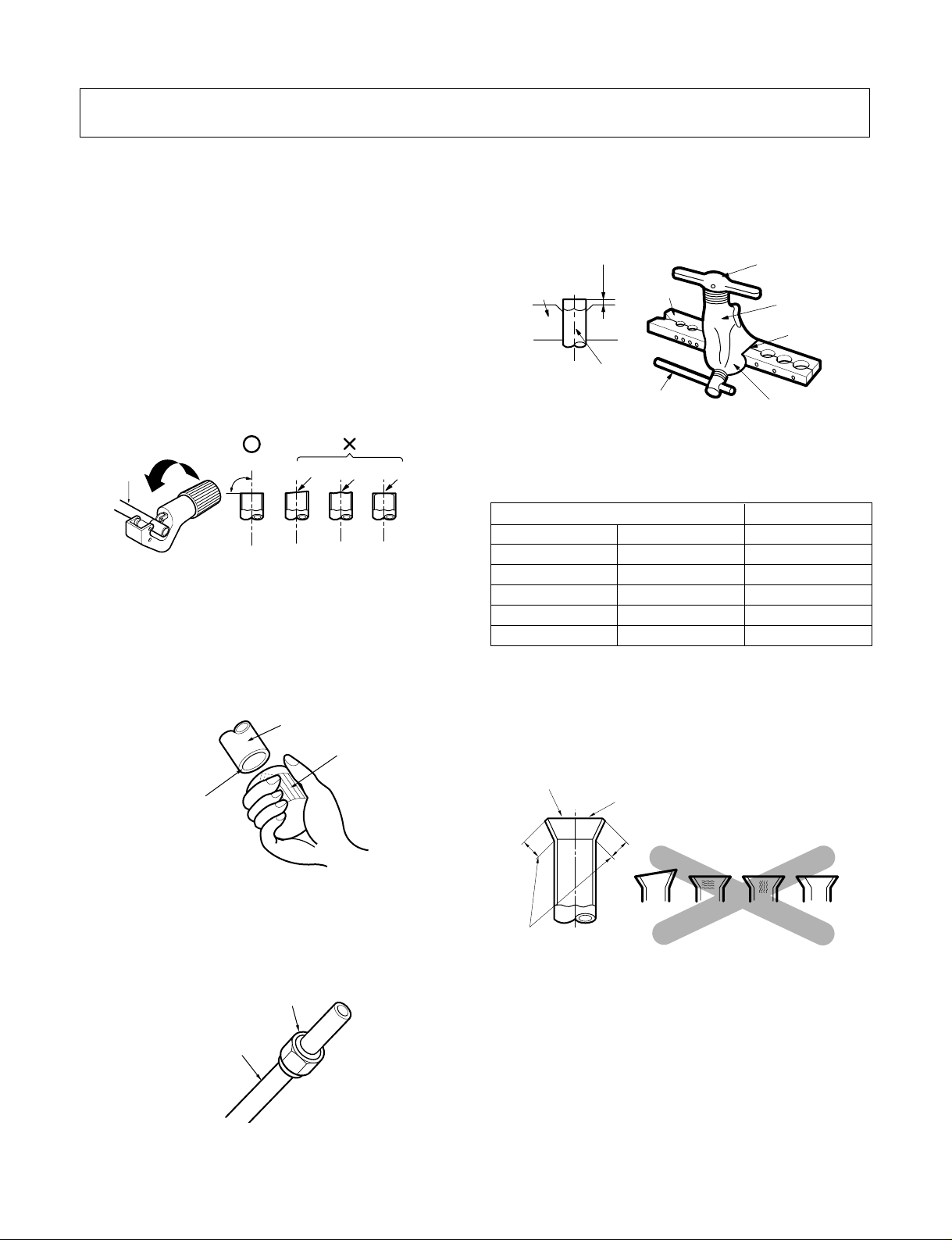
1) Flaring work
Main cause for refrigerant leakage is due to defect in
the flaring work. Carry out correct flaring work using the
following procedure.
1. Cut the pipes and the cable.
•
Use the piping kit accessory or pipes purchased locally.
• Measure the distance between the indoor and the
outdoor unit.
• Cut the pipes a little longer than the measured
distance.
• Cut the cable 1.5m longer than the pipe length.
2. Burr removal
• Completely remove all burrs from the cut cross section of pipe/tube.
• Put the end of the copper tube/pipe in a downward
direction as you remove burrs in order to avoid dropping burrs into the tubing.
3. Putting nut on
• Remove flare nuts attached to indoor and outdoor
unit, then put them on pipe/tube having completed
burr removal.
(not possible to put them on after flaring work)
4. Flaring work
• Firmly hold copper pipe in a die in the dimension
showninthetableabove.
• Carry out flaring work using flaring tool as shown
below.
5. Check
• Compare the flared work with figure below.
• If flare is noted to be defective, cut off the flared sec-
tion and re-flare it.
Copper
pipe
90°
Slanted Uneven Rough
Bar
Copper pipe
Clamp handle
Red arrow mark
Cone
Yoke
Handle
Bar
"A"
Inclined
Inside is shiny without scratches
Smooth all round
Even length
all round
Surface
damaged
Cracked Uneven
thickness
= Improper flaring =
Pipe
Reamer
Point down
Flare nut
Copper tube
mm inch mm
Ø6.35 1/4 0~0.5
Ø9.52 3/8 0~0.5
Ø12.7 1/2 0~0.5
Ø15.88 5/8 0~1.0
Ø19.05 3/4 1.0~1.3
Outside diameter
Page 26

-26-
2) Connection of piping Indoor
• Preparing the indoor unit's piping and drain hose for
installation through the wall.
• Remove the plastic tubing retainer(see illustration
below) and pull the tubing and drain hose away from
chassis.
• Replace the plastic tubing holder in the original position.
1. Route the indoor tubing and the drain hose in the
direction of rear right.
2. Insert the connecting cable into the indoor unit
from the outdoor unit through the piping hole.
• Do not connect the cable to the indoor unit.
• Make a small loop with the cable for easy
connection later.
3. Tape the tubing, drain hose, and the connecting
cable. Be sure that the drain hose is located at the
lowest side of the bundle. Locating at the upper
side can cause drain pan to overflow inside the
unit.
NOTE: If the drain hose is routed inside the room,
insulate the hose with an insulation material* so that
dripping from "sweating"(condensation) will not damage
furniture or floors.
*Foamed polyethylene or equivalent is recommended.
4. Indoor unit installation
• Hook the indoor unit onto the upper portion of the
installation plate.(Engage the two hooks of the rear
top of the indoor unit with the upper edge of the installation plate.) Ensure that the hooks are properly seated on the installation plate by moving it left and right.
Press the lower left and right sides of the unit against
the installation plate until the hooks engage into their
slots(clicking sound).
4. Connecting the pipings to the indoor unit and drain
hose to drain pipe.
• Align the center of the pipes and sufficiently tighten
the flare nut by hand.
For right rear piping
CAUTION
When install, make sure
that the remaining parts
must be removed clearly
so as not to damage the
piping and drain hose,
especially power cord
and connecting cable.
Loop
Tubing holder
Connecting
cable
Drain hose
Gas side
piping
Liquid side
piping
Connecting
cable
Drain hose
Drain hose
Indoor unit tubing Flare nut Pipes
Page 27

-27-
• Tighten the flare nut with a wrench.
• When extending the drain hose at the indoor unit,
install the drain pipe.
5. Wrap the insulation material around the connecting
portion.
• Overlap the connection pipe insulation material and
the indoor unit pipe insulation material. Bind them
together with vinyl tape so that there is no gap.
• Wrap the area which accommodates the rear piping
housing section with vinyl tape.
• Bundle the piping and drain hose together by wrapping them with vinyl tape for enough to cover where
they fit into the rear piping housing section.
1. Route the indoor tubing and the drain hose to the
required piping hole position.
2. Insert the piping, drain hose, and the connecting
cable into the piping hole.
For left rear piping
mm inch kg.m
Ø6.35 1/4 1.8
Ø9.52 3/8 4.2
Ø12.7 1/2 5.5
Ø15.88 5/8 6.6
Ø19.05 3/4 6.6
Outside diameter Torque
Wrench
Indoor unit tubing
Open-end wrench (fixed)
Connection pipe
Flare nut
Vinyl tape(narrow)
Adhesive
Drain pipe
Indoor unit drain hose
Plastic bands
Insulation material
Vinyl tape(narrow)
Connection
pipe
Connecting cable
Vinyl tape
(wide)
Wrap with vinyl tape
Indoor
unit pipe
Pipe
Wrap with vinyl tape
Drain hose
Pipe
Vinyl tape(wide)
Drain pipe
Connecting cable
Page 28

-28-
3. Insert the connecting cable into the indoor unit.
• Don't connect the cable to the indoor unit.
• Make a small loop with the cable for easy connection
later.
4. Tape the drain hose and the connecting cable.
• Connecting cable
5. Indoor unit installation
• Hang the indoor unit from the hooks at the top of the
installation plate.
• Insert the spacer etc. between the indoor unit and the
installation plate and separate the bottom of the
indoor unit from the wall.
6. Connecting the pipings to the indoor unit and the
drain hose to drain pipe.
• Align the center of the pipes and sufficiently tighten
the flare nut by hand.
• Tighten the flare nut with a wrench.
• When extending the drain hose at the indoor unit,
install the drain pipe.
7. Wrap the insulation material around the connecting portion.
• Overlap the connection pipe heat insulation and the
indoor unit pipe heat insulation material. Bind them
together with vinyl tape so that there is no gap.
• Wrap the area which accommodates the rear piping
housing section with vinyl tape.
mm inch kg.m
Ø6.35 1/4 1.8
Ø9.52 3/8 4.2
Ø12.7 1/2 5.5
Ø15.88 5/8 6.6
Ø19.05 3/4 6.6
Outside diameter Torque
Vinyl tape
Adhesive
Drain hose
Indoor unit drain hose
(narrow)
Plastic bands
Insulation material
Vinyl tape(narrow)
Connection
pipe
Connecting cable
Indoor
unit piping
Pipe
Vinyl tape
(wide)
Wrap with vinyl tape
Installation plate
Spacer
Indoor unit
8cm
Indoor unit tubing Flare nut Pipes
Wrench
Connection pipe
Flare nut
Open-end wrench (fixed)
Page 29

-29-
• Bundle the piping and drain hose together by wrapping them with cloth tape over the range within which
they fit into the rear piping housing section.
8. Reroute the pipings and the drain hose across the
back of the chassis.
9. Set the pipings and the drain hose to the back of
the chassis with the tubing holder.
• Hook the edge of tubing holder to tap on chassis and
push the bottom of tubing holder to be engaged at the
bottom of chassis.
10. Indoor unit installation
• Remove the spacer.
• Ensure that the hooks are properly seated on the
installation plate by moving it left and right.
Press the lower left and right sides of the unit against
the installation plate until the hooks engage into their
slots(clicking sound).
3) Connection of the pipes-Outdoor
1.Align the center of the pipings and sufficiently
tighten the flare nut by hand.
2. Finally, tighten the flare nut with torque wrench
until the wrench clicks.
• When tightening the flare nut with torque wrench,
ensure the direction for tightening follows the arrow on
the wrench.
mm inch kg.m
Ø6.35 1/4 1.8
Ø9.52 3/8 4.2
Ø12.7 1/2 5.5
Ø15.88 5/8 6.6
Ø19.05 3/4 6.6
Outside diameter Torque
Drain hose
Vinyl tape(narrow)
Pipe
Wrap with
vinyl tape(wide)
Piping for
passage through
piping hole
Outdoor unit
Gas side piping
(Bigger diameter)
Liquid side
piping
(Smaller
diameter)
Torque wrench
Outdoor unit
Liquid side piping
(Smaller Dia.)
Torque wrench
Gas side piping
(Bigger Dia.)
LS-Q096ABL
LS-Q096AAL
Tubing holder
Drain hose
Connecting
cable
Page 30

-30-
3. Connecting The Cable Between Indoor Unit and Outdoor Unit
1) Connect the cable to the Indoor unit.
• Connect the cable to the indoor unit by connecting the wires to the terminals on the control board in
dividually according to the outdoor unit connection. (Ensure that the color of the wires of the outdoor unit and
the terminal No. are the same as those of the indoor unit.)
The earth wire should be longer than the common wires.
Air
Conditioner
Main power source
If a power plug is not to be used, provide a circuit breaker
between power source and the unit as shown below.
Circuit Breaker
Use a circuit
breaker or time
delay fuse.
CAUTION
CAUTION
The power cord connected to the "A" unit should be
complied with the following specifications
(Type "B" approved by HAR or SAA).
Grade
5k~9K 12k~14k 18k 24k~28k 30k, 32k 36k, 38k
0.75 1.0 1.5 2.5 2.5 5.5
Unit(A) Indoor Indoor Indoor Indoor Outdoor Outdoor
Cable Type(B)
H05VV-F H05VV-F H05VV-F H05VV-F H05RN-F H05RN-F
NORMAL
CROSS
-SECTIONAL
AREA
5k~9k 12k~14k 18k 24k~28k
0.75 1.0 1.5 2.5
Cable Type(B) H07RN-F H07RN-F H07RN-F H07RN-F
NORMAL
CROSS
-SECTIONAL
AREA
Grade
30k, 32k 36k, 38k
0.75 0.75
Cable Type(B) H07RN-F H07RN-F
NORMAL CROSS
-SECTIONAL AREA
Grade
(mm2)
(mm
2
)
(mm2)
The power connecting cable connected to the indoor
and outdoor unit should be complied with the following
specifications
(Type "B" approved by HAR or SAA).
NORMAL
CROSS-SECTIONAL
AREA 0.75mm2
• The above circuit diagram is subject to change without notice.
• Be sure to connect wires according to the wiring diagram.
• Connect the wires firmly, so that not to be pulled out
easily.
• Connect the wires according to color codes by referring the wiring diagram.
CAUTION
• When installing, refer to the circuit diagram on the
Control Box of Indoor Unit.
• When installing, refer to the wiring diagram on the
Control Cover Inside Outdoor Unit.
Page 31

-31-
2) Connect the cable to the outdoor unit
1. Remove the control cover from the unit by loos-
ening the screw.
Connect the wires to the terminals on the control
board individually.
2. Secure the cable onto the control board with the
cord clamp.
3. Refix the control cover to the original position
with the screw.
4. Use a recognized circuit breaker "A"
between the power source and the unit.
A disconnecting device to adequately disconnect
all supply lines must be fitted.
Connecting
cable
Terminal block
(Pillar terminal)
Cover control
Outdoor unit
Outdoor unit
Over
5mm
Holder for
connecting
cable
Over 5mm
Terminal block
(Pillar terminal)
Holder for
power supply
cord
Cover control
Connecting cable
LS-Q096AAL
LS-Q096ABL
After the confirmation of the above conditions, prepare the wiring as follows:
1) Never fail to have an individual power circuit specifically for the air conditioner. As for the method of
wiring, be guided by the circuit diagram posted on the inside of control cover.
2) The screw which fasten the wiring in the casing of electrical fittings are liable to come loose from
vibrations to which the unit is subjected during the course of transportation. Check them and make
sure that they are all tightly fastened. (If they are loose, it could cause burn-out of the wires.)
3) Specification of power source.
4) Confirm that electrical capacity is sufficient.
5) See to that the starting voltage is maintained at more than 90 percent of the rated voltage marked on
thenameplate.
6) Confirm that the cable thickness is as specified in the power source specification.
(Particularly note the relation between cable length and thickness. (Refer to page 30))
7) Always install an earth leakage circuit breaker in a wet or moist area.
8) The following would be caused by voltage drop.
• Vibration of a magnetic switch, which will damage the contact point, fuse breaking, disturbance of the normal
function of the overload.
9) The means for disconnection from a power supply shall be incorporated in the fixed wiring and have an
air gap contact separation of at least 3mm in each active(phase) conductors.
CAUTION
7k~14k 18k 24k~28k 30k, 32k 36k, 38k
15 20 30 30 40
Circuit
Breaker
(A)
Grade
Page 32

-32-
4. Checking the Drainage and Forming the Pipings
1) Checking the drainage
1. To remove the front panel from the indoor unit.
• Set the air direction louvers up-and-down to the position(horizontally) by hand.
• Remove the securing screws that retain the front panel. Pull the lower left and right sides of the grille
towardyouandliftitoff.
2. To check the drainage.
• Pour a glass of water on the evaporator.
• Ensure the water flows through the drain hose of the
indoor unit without any leakage and goes out the drain
exit.
3. Drain piping
• The drain hose should point downward for easy drain
flow.
• Do not make drain piping.
2) Form the piping
1. Form the piping by wrapping the connecting portion of the indoor unit with insulation material and
secure it with two kinds of vinyl tapes.
• If you want to connect an additional drain hose, the
end of the drain outlet should be routed above the
ground. Secure the drain hose appropriately.
2. In cases where the outdoor unit is installed below
the indoor unit perform the following.
• Tape the piping, drain hose and connecting cable from
down to up.
• Secure the tapped piping along the exterior wall using
saddle or equivalent.
3. In cases where the Outdoor unit is installed above
the Indoor unit perform the following.
•
Tape the piping and connecting cable from down to up.
• Secure the taped piping along the exterior wall. Form
a trap to prevent water entering the room.
• Fix the piping onto the wall by saddle or equivalent.
Pull the right and
the left side.
Taping
Drain
hose
Pipings
Connecting
cable
Trap is required to prevent water
from entering into electrical parts.
Seal small openings
around pipings with a
gum type sealer.
Taping
Drain hose
Pipings
Connecting
cable
LS-Q096AAL LS-Q096ABL
Seal a small opening
around the pipings
with gum type sealer.
Trap
Trap
Downward slope
Do not raise
Accumulated
drain water
Tip of drain hose
dipped in water
Air
Waving
Water
leakage
Water
leakage
Ditch
Less than
50mm gap
Water
leakage
Page 33

-33-
1. Check that all tubing and wiring have been properly
connected.
2. Check that the gas and liquid side service valves are
fully open.
1. Prepare remote control
1. Remove the battery cover
by pulling it according to the
arrow direction.
2. Insert new batteries making
sure that the (+) and (–)of
battery are installed correctly.
3. Reattach the cover by
pushing it back into position.
NOTE:
• Use 2 AAA(1.5volt) batteries.Do not use recharge-
able batteries.
• Remove the batteries from the remote control if the
system is not going to be used for a long time.
2. Settlement of outdoor unit
• Anchor the outdoor unit with a bolt and nut(ø10mm)
tightly and horizontally on a concrete or rigid mount.
• When installing on the wall, roof or rooftop, anchor the
mounting base securely with a nail or wire assuming
the influence of wind and earthquake.
• In the case when the vibration of the unit is conveyed
to the hose, secure the unit with an anti-vibration
bushing.
3. Evaluation of the performance
Operate unit for 15~20 minutes, then check the system
refrigerant charge:
1. Measure the pressure of the gas side service valve.
2. Measure the temperature of the intake and discharge
of air.
3. Ensure the difference between the intake temperature and the discharge is more than 8°C(46°F) (Cooling) or (Heating).
4. For reference; the gas side pressure of optimum condition is as below.(Cooling)
NOTE: If the actual pressure is higher than shown, the
system is most likely over-charged, and charge
should be removed. If the actual pressure are
lower than shown, the system is most likely
undercharged, and charge should be added.
The air conditioner is now ready for use.
Bolt
Tubing connection
Discharge
temperature
Discharge air
Intake temperature
5. Test Running
R-22 35°C(95°F) 4~5kg/cm2G(56.8~71.0 P.S.I.G.)
Outside ambient
TEMP.
Refrigerant
The pressure of the gas side
service valve.
This is performed when the unit is to be relocated
or the refrigerant circuit is serviced.
Pump Down means collecting all refr igerant i n the
outdoor unit without loss in refrigerant gas.
CAUTION:
Be sure to perform Pump Down procedure with the
unit cooling mode.
Pump Down Procedure
1. Connect a low-pressure gauge manifold hose to
thechargeportonthegassideservicevalve.
2. Open the gas side service valve halfway and purge
the air from the manifold hose using the refrigerant
gas.
3. Close the liquid side service valve(all the way in).
4. Turn on the unit's operating switch and start the
cooling operation.
5. When the low-pressure gauge reading becomes 1
to 0.5kg/cm2 G(14.2 to 7.1 P.S.I.G.), fully close the
gas side valve stem and then quickly turn off the
unit. At that time, Pump Down has been completed
and all refrigerant gas will have been collected in
the outdoor unit.
PUMP DOWN
Page 34

-34-
START/STOP BUTTON
Operation starts when this button is pressed and stops
when the button is pressed again.
OPERATION MODE SELECTION BUTTON
Used to select the operation mode.
ROOM TEMPERATURE SETTING BUTTONS
Used to select the room temperature.
INDOOR FAN SPEED SELECTOR
Used to select fan speed in four steps
low, medium, high and CHAOS.
JET COOL
Used to start or stop the speed
cooling. (Speed cooling operates
super high fan speed in cooling mode.)
CHAOS SWING BUTTON
Used to stop or start louver movement and set the
desired up/down airflow direction.
ON/OFF TIMER BUTTONS
Used to set the time of starting and stopping operation.
TIME SETTING BUTTONS
Used to adjust the time.
TIMER SET/CANCEL BUTTONS
Used to set the timer when the desired time is obtained
and to cancel the Timer operation.
SLEEP MODE AUTO BUTTON
Used to set Sleep Mode Auto operation.
AIR CIRCULATION BUTTON
Used to circulate the room air without cooling or heating.
ROOM TEMPERATURE CHECKING BUTTON
Used to check the room temperature.
PLASMA(OPTION)
Used to start or stop the plasma-purification function.
RESET BUTTON
Used prior to resetting time or after replacing batteries.
HORIZONTAL AIRFLOW DIRECTION CONTROL BUTTON(NOTONALLMODELS)
Used to set the desired horizontal airflow direction.
Operation
Name and Function-Remote Control
The remote control transmits the signals to the system.
1
2
345
678
9
10
11
12
13
14
15
ON OFF
PLASMA
SET
CANCEL
6
1
3
5
4
Cooling Operation
Auto Operation
Healthy Dehumidification Operation
Flip-up door
(opened)
Heating Operation
Signal transmitter
10
11
12
13
1415
7
8
9
2
•
Cooling Model( ), Heat Pump Model( )
Remote Control
Operation Mode
Page 35

-35-
Name and Function-Remote Control
The remote control transmits the signals to the system.
START/STOP BUTTON
Operation starts when this button is pressed and stops
when the button is pressed again.
OPERATION MODE SELECTION BUTTON
Used to select the operation mode.
ROOM TEMPERATURE SETTING BUTTONS
Used to select the room temperature.
INDOOR FAN SPEED SELECTOR
Used to select fan speed in four steps low, medium, high
and CHAOS.
JET COOL
Used to start or stop the speed cooling. (Speed cooling
operates super high fan speed in cooling mode.)
CHAOS SWING BUTTON
Used to stop or start louver movement and set the desired
up/down airflow direction.
ON/OFF TIMER BUTTONS
Used to set the time of starting and stopping operation.
TIME SETTING BUTTONS
Used to adjust the time.
TIMER SET/CANCEL BUTTON
Used to set the timer when the desired time is obtained
andtocanceltheTimeroperation.
SLEEP MODE AUTO BUTTON
Used to set Sleep Mode Auto operation.
AIR CIRCULATION BUTTON
Used to circulate the room air without cooling or heating.
ROOM TEMPERATURE CHECKING BUTTON
Used to check the room temperature.
PLASMA(OPTIONAL)
Used to start or stop the plasma-purification function.
HORIZONTAL AIRFLOW DIRECTION CONTROL
BUTTON (NOT ON ALL MODELS)
Used to set the desired horizontal airflow direction.
RESET BUTTON
Used prior to resetting time or after replacing batteries.
2ndFButton
Used prior to using modes printed in blue at the bottom of
buttons.
1
2
3
4
5
6
789
10
11
12
13
14
15
16
ON
OFF
CANCEL
SET
1
3
5
4
9
10
12
14
16
7
2
8
13
15
11
6
Cooling Operation
Auto Operation
Healthy Dehumidification Operation
Flip-up door
(opened)
Heating Operation
Signal transmitter
•
Cooling Model( ), Heat Pump Model( )
Remote Control
Operation Mode
Page 36

-36-
Disassembly of the parts (Indoor unit)
Warning :
Disconnect the unit from power supply before making
any checks.
Be sure the power switch is set to “OFF”.
To remove the Grille from the Chassis.
• Set the up-and-down air discharge louver to open
position (horizontally) by finger pressure.
• Remove the securing screws.
• To remove the Grille, pull the lower left and right
side of the grille toward you (slightly tilted) and lift it
straight upward.
1. Before removing the control box, be sure to
take out the wire screwed at the other end.
Display
P.C.B
Conductor
Step Motor
Conductor
Earth
Conductor
Motor
Conductor
Sensor
Conductor
Earth
Conductor
Page 37

-37-
2. To remove the Control Box.
• Remove securing screws.
• Pull the control box out from the chassis careful-
ly.
3. To remove the Discharge Grille.
• Unhook the discharge grille and pull the discharge grille out from the chassis carefully.
4. To remove the Evaporator.
• Remove 3 screws securing the evaporator(at the
left 2EA in the Eva Holder, at the right 1EA).
Caution label
When repair, do not damage the Caution
label.
Caution label
Page 38

-38-
• Unhook the tab on the right inside of the chassis
at the same time, slightly pull the evaporator
toward you until the tab is clear of the slot.
5. To remove the Motor Cover
• Remove 2 securing screw.
• Pull the motor cover out from the chassis
carefully.
6. To remove the Cross-Flow Fan
• Loosen the screw securing the cross-flow fan to
the fan motor (do not remove).
• Lift up the right side of the cross-flow fan and the
fan motor, separate the fan motor from the
cross-flow fan.
• Remove the left end of the cross-flow fan from
the self-aligning bearing.
Motor cover
Page 39

2-way, 3-way Valve
2-way Valve (Liquid Side) 3-way Valve (Gas Side)
Shaft position Shaft position Service port
Closed Closed Closed
(with valve cap) (with valve cap) (with cap)
Open Closed Open
(counter-clockwise) (clockwise) (push-pin or with
vacumm pump)
Open Open Closed
(with valve cap) (with valve cap) (with cap)
Closed Open Open
(clockwise) (counter-clockwise) (connected manifold
gauge)
Open Open Open
(with charging
cylinder)
Open Open Open
(with charging
cylinder)
Open Open
Open Open
Works
Shipping
Air purging
(Installation)
Operation
Pumping down
(Transfering)
Evacuation
(Servicing)
Gas charging
(Servicing)
Pressure check
(Servicing)
Gas releasing
(Servicing)
1.
2.
3.
4.
5.
6.
Valve cap
Open position
Closed position
Pin
Service
port
Service
port cap
To outdoor unit
Flare nut
To
piping
connection
To outdoor unit
Hexagonal wrench (4mm)
Open position
Closed position
To
piping
connection
Flare nut
-39-
Open
(with charging cylinder)
Open
(with charging cylinder)
Page 40

1. Air purging
Required tools : hexagonal wrench, adjustable
wrench, torque wrenches, wrench to
hold the joints, and gas leak detector.
The additional gas for air purging has been charged
in the outdoor unit.
However, if the flare connections have not be done
correctly and there gas leaks, a gas cylinder and the
charge set will be needed.
The air in the indoor unit and in the piping must be
purged. If air remains in the refrigeration pipes, it will
affect the compressor, reduce to cooling capacity, and
could lead to a malfunction.
• Procedure
(1) Recheck the piping connections.
(2) Open the valve stem of the 2-way valve coun-
terclockwise approximately 90°, wait 10 seconds, and then set it to closed position.
– Be sure to use a hexagonal wrench to operate
the valve stem.
(3) Check for gas leakage.
– Check the flare connections for gas leakage.
(4) Purge the air from the system.
– Set the 2-way valve to the open position and
remove the cap from the 3-way valve’s service
port.
– Using the hexagonal wrench to press the valve
core pin, discharge for three seconds and then
wait for one minute. Repeat this three times.
(5) Use torque wrench to tighten the service port
nut to a torque of 1.8kg.cm.
(6) Set the 3-way valve to the back seat.
(7) Mount the valve stem nuts to the 2-way and 3-
way valves.
(8) Check for gas leakage.
– At this time, especially check for gas leakage
from the 2-way and 3-way valve’s stem nuts,
and from the service port nut.
Caution
If gas leakage are discovered in step (3) above,
take the following mesures :
If the gas leaks stop when the piping connections
are tightened further, continue working from step (4).
If the gas leaks do not stop when the connections
are retightened, repair the location of the leak, discharge all of the gas through the service port, and
then recharge with the specified amount of gas
from a gas cylinder.
Service port nut:
Be sure, using a torque wrench to tighten the service port nut (after using the service port), so that it prevents the
gas leakage from the refrigeration cycle.
* CAUTION : Do not leak the gas in the air during Air purging.
Liquid side
Outdoor unit
3-way
valve
Gas side
Indoor unit
2-way
valve
Open
Clsed
-40-
Page 41

2. Pumping down
• Procedure
(1) Confirm that both the 2-way and 3-way valves
are set to the open position.
– Remove the valve stem caps and confirm that
the valve stems are in the raised position.
– Be sure to use a hexagonal wrench to operate
the valve stems.
(2) Operate the unit for 10 to 15 minutes.
(3) Stop operation and wait for 3 minutes, then
connect the charge set to the service port of
the 3-way valve.
– Connect the charge hose with the push pin to
the service port.
(4) Air purging of the charge hose.
– Open the low-pressure valve on the charge set
slightly to air purge from the charge hose.
(5) Set the 2-way valve to the closed position.
(6) Operate the air conditioner at the cooling
cycle and stop it when the gauge indicates
1kg/cm2g.
(7) Immediately set the 3-way valve to the closed
position.
– Do this quickly so that the gauge ends up indi-
cating 3 to 5kg/cm2g.
(8) Disconnect the charge set, and mount the 2-
way and 3-way valve’s stem nuts and the service port nut.
– Use torque wrench to tighten the service port
nut to a torque of 1.8 kg.m.
– Be sure to check for gas leakage.
Lo
Closed
Purge the air
Outdoor unit
Indoor unit
Liquid side
Gas side
CLOSE
Open
2-Way
valve
3-Way
valve
CLOSE
-41-
Page 42

1) Re-air purging
(Re-installation)
• Procedure
(1) Confirm that both the 2-way valve and the 3-
way valve are set to the closed position.
(2) Connect the charge set and a gas cylinder to
the service port of the 3-way valve.
– Leave the valve on the gas cylinder closed.
(3) Air purging.
– Open the valves on the gas cylinder and the
charge set. Purge the air by loosening the flare
nut on the 2-way valve approximately 45° for 3
seconds then closing it for 1 minute; repeat 3
times.
– After purging the air, use a torque wrench to
tighten the flare nut on the 2-way valve.
(4) Check for gas leakage.
– Check the flare connections for gas leakage.
(5) Discharge the refrigerant.
– Close the valve on the gas cylinder and dis-
charge the refrigerant until the gauge indicates
3 to 5 kg/cm2g.
(6) Disconnect the charge set and the gas cylin-
der, and set the 2-way and 3-way valves to the
open position.
– Be sure to use a hexagonal wrench to operate
the valve stems.
(7) Mount the valve stem nuts and the service
port nut.
– Use torque wrench to tighten the service port
nut to a torque of 1.8 kg.m.
– Be sure to check for gas leakage.
* CAUTION:
Do not leak the gas in the air during Air Purging.
Lo
Closed
OPEN
Closed
Gas cylinder
R22
Outdoor unit
Indoor unit
Liquid side
Gas side
CLOSE
2-Way
valve
3-Way
valve
-42-
Page 43

2) Balance refrigerant of the 2-way, 3-way valves
(Gas leakage)
• Procedure
(1) Confirm that both the 2-way and 3-way valves
are set to the back seat.
(2) Connect the charge set to the 3-way valve’s
port.
– Leave the valve on the charge set closed.
– Connect the charge hose with the push pin to
the service port.
(3) Open the valve (Lo side) on the charge set
and discharge the refrigerant until the gauge
indicates 0 kg/cm2G.
– If there is no air in the refrigerant cycle (the
pressure when the air conditioner is not running is higher than 1 kg/cm2G), discharge the
refrigerant until the gauge indicates 0.5 to 1
kg/cm2G. if this is the case, it will not be necessary to apply a evacuatin.
– Discharge the refrigerant gradually; if it is dis-
charged too suddenly, the refrigeration oil will
also be discharged.
Lo
Open
Open
3-Way
valve
2-Way
valve
Gas side
CLOSEOPEN
Outdoor unit
Liquid side
Indoor unit
-43-
Page 44

3. Evacuation
(All amount of refrigerant leaked)
• Procedure
(1) Connect the vacuum pump to the charge set’s
center hose
(2) Evacuation for approximately one hour.
– Confirm that the gauge needle has moved
toward -76 cmHg (vacuum of 4 mmHg or less).
(3) Close the valve (Lo side) on the charge set,
turn off the vacuum pump, and confirm that
the gauge needle does not move (approximately 5 minutes after turning off the vacuum
pump).
(4) Disconnect the charge hose from the vacuum
pump.
– Vacuum pump oil.
If the vacuum pump oil becomes dirty or
depleted, replenish as needed.
Lo
Open
Open
Vacuum pump
2-Way
valve
Outdoor unit
Liquid side
Indoor unit
Gas side
3-Way
valve
CLOSE
OPEN
-44-
Page 45

4. Gas Charging
(After Evacuation)
• Procedure
(1) Connect the charge hose to the charging
cylinder.
– Connect the charge hose which you dis-con-
nected from the vacuum pump to the valve at
the bottom of the cylinder.
– If you are using a gas cylinder, also use a scale
and revers the cylinder so that the system can
be charged with liquid.
(2) Purge the air from the charge hose.
– Open the valve at the bottom of the cylinder
and press the check valve on the charge set to
purge the air. (Be careful of the liquid refrigerant). The procedure is the same if using a gas
cylinder.
(3) Open the valve (Lo side on the charge set and
charge the system with liquid refrigerant.
– If the system can not be charged with the spec-
ified amount of refrigerant, it can be charged
with a little at a time (approximately 150g each
time) while operating the air conditioner in the
cooling cycle; however, one time is not sufficient, wait approximately 1 minute and then
repeat the procedure (pumping down-pin).
(4) Immediately disconnect the charge hose from
the 3-way valve’s service port.
– Stopping partway will allow the gas to be dis-
charged.
– If the system has been charged with liquid
refrigerant while operating the air conditioner
turn off the air conditioner before disconnecting
the hose.
(5) Mount the valve stem nuts and the service
port nut.
– Use torque wrench to tighten the service port
nut to a torque of 1.8 kg.m.
– Be sure to check for gas leakage.
\
This is different from previous procedures.
Because you are charging with liquid refrigerant
from the gas side, absolutely do not attempt to
charge with larger amounts of liquid refrigerant
while operating the air conditioner.
-45-
Indoor unit
Liquid side
Gas side
Check valve
Charging
cylinder
Lo
(1)
OPEN
CLOSE
Open
Outdoor unit
2-Way
valve
Open
3-Way
valve
Page 46

Cycle Troubleshooting Guide
Trouble analysis
1. Check temperature difference between intake and discharge air and operating current.
Temp. Difference
Temp. difference : approx. 0°C
Current : less than 80% of
rated current
Temp. difference : approx. 8°C
Current : less than 80% of
rated current
Temp. difference : less than 8°C
Current : over the reated
current
Temp. difference : over 8°C
Operating Current
• All amount of refrigerant leaked
out. Check refrigeration cycle.
• Refrigerant leakege
Clog of refrigeration cycle
Defective compressor
• Excessive amount of refrigerant
• Normal
Notice :
Temperature difference between intake and discharge air depends on room air humidity. When the room air
humidity is relativery higher, temperature difference is smaller. When the room air humidity is relatively lower temperature difference is larger.
2. Check temperature and pressure of refrigeration cycle.
Notice :
1. The suction pressure is usually 4.5~6.0 kg/cm2G(Cooling) at normal condition.
2. The temperature can be measured by attaching the thermometer to the low pressure tubing and wrap it with
putty.
Suction pressure Temperature
(Compared with (Compared with Cause of Trouble Description
the normal value) the normal valve)
Defective compressor Current is low.
Defective 4-way reverse valve
Excessive amount of High pressure does not quickly
Normal refrigerant rise at the beginning of
operation.
Insufficient amount of Current is low.
Lower Higher refrigerant (Leakage)
Clogging Current is low.
High
Higher
-46-
Page 47

-47-
Electronic Parts Troubleshooting Guide
1. Product does not operate at all.
(* Refer to Electronic Control Device drawing and Schematic diagram.)
Turn off Main Power
Turn on Main Power
Does "beeping" sound is made from the Indoor Unit?
Primarily, the operating condition of Micom is OK.
Check the voltageof power(About AC220V,60Hz)
(About AC 220/240V, 50Hz)
• Main power's voltage
• Voltage applied to the unit
• Connecting method of Indoor/Outdoor connecting
cable
• Check PWB Assembly
-Fuse
- Pattern damage
- Varistor(ZNR01J)
Check the connection housing forcontacting
• Connector related to CN-TAB1, RY-COMP NO.3
• Connector related to CN-MOTOR
• Connector contacting of Outdoor Fan/Compressor
• Display PWB Assembly Check
Check each load(Indoor/Outdoor Fan Motor, Compressor, Stepping Motor) and contacting
condition of related connector
Main PCB Board Operation Check
Items
• SMPS Transformer
(Indoor unit)
- Input Voltage
- Output Voltage(ZD02D)
• IC04D(7805) Output
(Indoor/Outdoor unit)
• IC01A(KIA7036, Reset IC)
X01(8MHz)
• Replace Trans
• Replace IC04D
• Replace faulty parts
- About AC220V/240V±10% - Check the power voltage
- About DC12V
• DC+5V
• Voltage of Micom No. 2,
(DC +4.5V over) and Soldering condition.
Content Remedy
NO
YES
(After 10 seconds)
Page 48

-48-
2. The product is not operate with the remote control.
Turn on Main Power
While the compressor has been stopped, the compressor does not
operate owing to the delaying function for 3 minutes after stopped.
Caused by other parts except the remote control
Cause by the remote control
When the mark( ) is display edin LCDscreen, replace
battery .
Check the contact of CN-DISP1 connector.
When the compressor stopped Indoor Fan is driven by a low speed.
At this point the wind speed is not controlled by the remote controller.
(When operated in the Sleeping Mode, the wind speed is set to the
low speed by force.)
Check Display PWB Assembly
- Voltage between CN DISP1 - :DC+5V
Check the connecting circuit betweenthe remotecontroller
MICOM (No. ) - R17(2Ω)-IRLED-TR-R16(2.2KΩ).
Check point
• Check the connecting circuit between CN-DISP1
-
R01L(5.1K) - C01L(680pF) - MICOM PIN
• Check Receiver Assembly
43
2
Page 49

-49-
3. Compressor/Outdoor Fan are unable to drive.
Turn on Main Power
Operate "Cooling Mode( )" by setting the desired temperature of the
remote controller is less than one of the indoor temperature by 1°C at least.
When in Air Circulation Mode, Compressor/Outdoor Fan is stopped.
Check the sensor for indoor temperature is attached as close as to be
effected by the temperature of Heat Exchanger(EVA).
When the sensor circuit for indoor temperature and connector are in bad
connection or are not engaged, Compressor/Outdoor Fan is stopped.
• Check the related circuit of RY-FAN.
•Check the indoor temperature sensor is disconnected or not(About10kΩ /at25°C).
Turn off Main Power
• Check the electrical wiring diagram of outdoor side.
• Check the abnormal condition for the component of Compressor/Out-
door Fan Motor.
• Check the "open" or "short" of conmecting wires between indoor and
outdoor.
Check Relay(RY - COMP) for driving compressor.
• When the power(About AC220V/240V) is applied to the connecting wire
terminal support transferred to compressor, PWB Assembly is normal.
• Check the circuit related to the relay.
Check point COMP ON COMP OFF
Between Micom(No.
DC5V DC0V
62) and GND
Between IC01M(No. 14) BelowDC 1V
About DC12V
and GND (app)
Page 50

-50-
Check the TRIAC high speed operation by remote control.
(The Indoor Fan Motor is connected)
Turn off Main power
Check the connection of CN-MOTOR
Check the Fan Motor
Check the Fuse(AC250V/T2A)
Turn ON Main Power
Check the related circuit of indoor Fan Motor.
• The pin NO 58 of Micom, and the part for driving TRIAC(the input and
output signal of IC01M, PIN NO 7, 10)
• Check the pattern
• Check the TRIAC
- TRIACOpen: Indoor Fan Motor never operate
- TRIACshort: Indoor Fan Motor always operates in case of ON or OFF.
4. When indoor Fan does not operate.
The voltage of PIN NO 1(orange) and 3(yellow) of CN-MOTOR.
About AC 180V over About AC 50V over
TRIAC is not damaged TRIAC Check
Page 51

-51-
• Confirm that the Vertical Louver is normally geared with the shaft of
Stepping Motor.
• If the regular torque is detected when rotating the Vertical Louver with
hands Normal
• Check the connecting condition of CN-U/D Connector
• Check the soldering condition(on PWB) of CN-U/D Connector
If there are no problems after above checks
• Confirm the assembly conditions that are catching and interfering parts
in the rotation radial of the Vertical Louver
5. When Vertical Louver does not operate.
Check the operating circuit of the Vertical Louver
• Confirm that there is DC+12V between pin (RED) of CN-U/D and
GND.
• Confirm that there is a soldering short at following terminals.
- Between , , and of MICOM
- Between , , and of IC01M
- Between , , and of IC01M
60 61 62 63
Page 52

-52-
6. When Heating does not operate
Operate “Heating Mode( )” by setting the desired temperature of the
remote control is higher than one of the indoor temperature by 2°Cat
least.
In heating Mode, the indoor fan operates in case the pipe temperature
is higher than 28°C.
Check the connector of intake and pipe sensor(thermistors)
• Chec kthe related circuit of RY-4WAY
• Chec kthe indoor room temperature is disconnected or not (about
10KΩ/at 25°C).
• Chec kthe indoor pipe temperature is disconnected or not (about
5KΩ/at 25°C).
Turn ON Main Power
Check the DC voltage on the PWB ASSEMBLY
• The details of check are as followings
Check point
Between Micom
(NO.59) and GND
Between IC01M
(NO.11) and GND
Comp ON
DC 5V
Below DC 1V
Comp OFF
DC 0V
About DC
12V
Check point
Between Micom
(NO.51) and GND
Between IC02M
(NO.11) and GND
4wayON
DC 5V
Below DC 1V
4wayOFF
DC 0V
About DC 12V
Check point
Between Micom
(NO.53) and GND
Between IC02M
(NO.12) and GND
Fan ON
DC 5V
BelowDC1V
Fan OFF
DC 0V
About DC 12V
• Comp Relay.
• 4 way Relay
• Outdoor fan Relay
Page 53

-53-
Turn off Main Power
• Check the electrical wiring diagram of outdoor side.
• Check the abnormal condition for the component of Compressor/Out-
door Fan Motor, 4 way.
• Check the "open" or "short" of connecting wires between indoor and
outdoor.
Page 54

-54-
Electronic Control Device
(1) MAIN P.W.B ASSEMBLY (AC PART)
• TOP VIEW • BOTTOM VIEW
(1) MAIN P.W.B ASM (AC)
• COOLING MODEL • HEAT PUMP MODEL
Page 55

-55-
(2) MAIN P.W.B ASSEMBLY (DC PART)
• TOP VIEW • BOTTOM VIEW
• TOP VIEW • BOTTOM VIEW
Page 56

-56-
• TOP VIEW • BOTTOM VIEW
6871A20220
6871A20219
6871A20218
6871A20217
6871A20216
6871A20164
Page 57

-57-
(3) DISPLAY ASSEMBLY
– 6871A20194
TOP VIEW
BOTTOM VIEW
BOTTOM VIEW
– 6871A30009
TOP VIEW
BOTTOM VIEW
– 6871A20227
TOP VIEW
Page 58

-58-
BOTTOM VIEW
K
K
– 6871A20390
TOP VIEW
BOTTOM VIEW
C01A
C01A
88SEG
– 6871A20391
TOP VIEW
Page 59

Schematic Diagram
TELEPHONE-CONTROL MODEL ONLY
-59-
Page 60

-60-
Cooling Model
• LED TYPE
Page 61

-61-
Cooling Model
• HVB TYPE(PLASMA)
Page 62

-62-
Heat Pump Model
• LED TYPE
VP
16
1
5V
5V
R09H
C104S
Q03T
A104S
Q01T
5V
1K
C104S
Q02T
CN-TELE
C01D
C01T
100uF/25V
0.001uF
1N4148
D01T
A104S
Q04T
50V
TX
5V
C06H
0.1uF/50V
R01T
0.001uF
50V
C02T
RX
1K
CST-3.58M
OSC02B
ZD02H~ZD03H
5.1V, 1/2W
4.7K
R02A
R03A
100
10uF
50V
C01A
RST
R01A
1K
+
KIA7036P
IC01A
1
2
3
5V
DSOQ2Q3Q0DE
EST
15
Q1
D2
NC
X2
D3
DV
121314
VSSD0NC
OE
10
11
D1
100K
VREF
X1
R01X
58964
7
0.1uF/50V
C02H
RY-HOOK
ZNR01
R19H
BSP351L
R15H
10K
R18H
2.7 1/2W
2.7 1/2W
BD
C05H
100V
0.01uF
G6A-234P,5V
HR93F,5V
8
4
R12H
LM358
OP-AMP
1K
-
+
6
5
5V
ZD04H~ZD05H
CN-PHONE
3.9V, 1/2W
1uF DC250V
C01H
ZD05H
ZD04H
R01H
6.2K/1W
RST
DE
BD
100K
R07H
4.7K
R03H
7.5K
C03H
22uF
50V
+
R14H
R13H
750
270
ZD02H
C08H
7
50V
0.1uF
0.15uF
63V
C11H
ZD03H
5V
R05H
27
Q03M
2222A
2
27
3
R06H
63V
Q01M
C3198Y
R01M
4.7K
C09H
1uF
+
1N4004
D01M
100K
R16H
TRANS
T1
1/4W
6.2K
R02H
ZD01H
1.5KE56A
1N4004
D01H~D04H
KTC2016
PC01H
1
R04H
4
TLP621BL
5V
Q02M
RA3
2K
0.1uF
C02X
16
OSC215OSC1
14
4
5
VSS
MCLR3T0CLK
RB4
9
RB3
13
6
RB0
RB5
10
RB6
11
12
8
7
RB2
RB1
RB7
VDD
OP2
10K
DE
DSO
5V
IC-DTMF
(ST9170)
HT9170B
VN
VDD
18
GS
RI
17
50V
51K
R17H
2
3
5V
R01B
1M
Q0Q3Q2
Q1
50V
CST-4.00MGW
OSC01B
C01X
0.01uF
16V
MICOM
RA1
18
17
RA0
1
RA2
2
PIC16C54CR
C04H
1uF
R08H
5V
OP1
10K
TX
RX
S/W(FORCE)
Operation
Defrost
Timer
Sleep
9
13
14
12
16
15
11
10
17
22
20
19
21
18
23
24
63
4
1
3
2
64
5
6
8
7
59
61
60
62
58
57
40
31
25
28
27
26
30
29
36
35
37
33
38
39
34
32
50
53
54
55
51
52
56
45
46
48
47
49
44
41
42
43
DISPLAY
R02E,20
UPD780023AGC-C
ZBF503D
ZD02D
VOLTAGE GND
BZX55C11
2
1
6
8
745
3
HVB
LED1
LED2
LED3
LED4
C01A
RECEIVER
104
Vout
GND
Vcc
R02G 220
R03G 220
R04G 220
R01G 220
AC PART
5V
25V
10V SD
R02D
DC LOW
1/6W
20K
S78DL05L 1W
103
C08D
+
220
C09D
I
O
7805
IC04D
25V
103
C07D
12V
25V SD
C06D
330
L1
IC01G
KID65004AF
HVB OUT
12V
33
1
1
3
2
1
2
2
1
2
1
322
CN-CONT
CN-12V
1
1
3
2
3
CN-HVB
Option
1
2
5V
R11H~R14H
20K 2012
receiver
+
6 66
8
7
8
7
8
7
2
1
5
4
3
4
5
1
2
33
4
251
5V
9
5V
10V
C02L
220uF SD
5V
R11H
OJ1H
OJ2H
OJ3H
8
7
6
5
EEPROM
Vcc
SCL
SDA
WP
G
123
A0
A14A2
CAT24WC01J
R14H
R13H
R12H
20K
R01P
2012
R02P
20K
2012
OJ4H
5V
8
20K
R02F
7
3
4
5
2
6
1
5V
Vss0
Vdd0
C04C
103
Ad1dV
NEC
TERMINAL BOARD
STO2D-200
SD01D
TNY266P
DC HIGH
VOLTAGE GND
D
5
4
1
IC02D
DC HIGH
VOLTAGE GND
TLP421(V4 BL)
C05D
472M
32
104
50V
C02D
EN
4
S
2
BP
1
D07D
UG2D
470/35V/SD
C03D
681
RY-4WAY
1/6W
R03D
39
+
C04D
1
8
5V
CN-ACDC
CN-ACDC2
INT
3
6
2
7
12V
SMPS
5
4
4
5
7
2
6
3
RY-FAN
RY-COMP
4.7uF
VOLTAGE GND
TLP421(V4 BL)
450V/SD
IC01D
DC LOW
IC03D
LL4148
D08D
VOLTAGE GND
1
4
DC HIGH
2
3
1/4W
300K
R06D
NTC SCK-102
+
C01D
INT
INDOOR FAN12V
8
1
12V
12V
R05D
1/4W
300K
3216
5V
27k
1/6W
R04D
D05D
1N4007
IN4007
D01C
D01A
IN4007
R01E
1K
1%
OR1H
F1
OR5H
Med
L2
10nH
Hi
OR6H OR3H
O/L
OR2H
F2
OR4H
Low
C02C
220uF
10V/SD
5V
+
5V
R21H
INT
4WAY
5V
FAN
COMP
R22H
R25H
R26H
R24H
R23H
R21H~R26H
12.1K, 1%
5V
X2
RESET
AVdd
AVref
ssV
A
C03C
103
INT1X1Vss1
INT0
B
Z
CSTS0800MG03-T2
CRTL8.00MSOT
OSC01B
5V
R01B
1M
Q01C
2SC5343
KTC3198-Y
33
6.2K
12.1K
INDOOR FAN
12V
1%
R05H
10K
11
2 2
3.6V
2
1
C01A
3
50V
0.01
R02A,20K
R04H
R02H
KIA7036P
S7136
IC01A
5V
5V
680pF/50V
C01L
R01L 5.1K
R02L,1K
R07D
56K
R06D
12K
BZ01E
5V
receiver
PKM13EPY-4002
5V
INT
44
CN-TH
SM1L43
TRAICS
RY-FAN
250V/T2A
G5N-1A(G5NB-1A)
RY-4WAY
G5N-1A(G5NB-1A)
TVR10561
METAL FILM
METAL FILM
47nM/275V/435D
100nM/275V/436D
4
4
3
3
1/4W
560
R04J
INDOOR FAN
IN4007
D01D
IN4007
D01B
C02J
12V
IC01J
TR01J
TLP762JF
15mH/1A
NF01J
C01J
R02J
100,1/2W
T1
FUSE
ZNR01J
4
5
3
1
2
T2
R03J
680
1/2W
11
13
RY-COMP
G4A-1A-E-LG
12
15
1
4
3
1
1
CN-TAB1
120, 1/2W
RY-COMP
100nF/275V/436D
METAL FILM
C03J
ZNR02J
TVR10561
1
12V
2
6
8
R01J
231
231
CN-MOTOR
12V
RY-COMP
1
3
6
9
5
2
4
SH-CAPACITOR
FAN
MOTOR
INDOOR
PIPE-TH
ROOM-TH
+
123
3.6V
1
1(L)
1
N
L
AC220~240V
50/60Hz
COMPRESSOR
524
2(N)
4
3
OUTDOOR
FAN MOTOR
4-WAY
PK
16
(UP/DOWN)
STEPPING MOTOR
9
KID65004AF
DC PART
CN-U/D
3
2
YLORRD
4
5
PK
BL
1
324
5
1
COMP
HVB OUT
12V
INDOOR FAN
3
2
8
1
4
5
IC01M
6
7
1
STEPPING MOTOR
(LEFT/RIGHT)
BL
2
2
Option
Q03T
C104S
Q02T
A104S
4WAY
9
8
121314 1011
43
7
5
6
FAN
2
15
KID65004AF
IC02M
CN-L/R
RD
545
4
OR
1
1
3
3
YL
12V
1K
5V
C03T
102
R01T
102
A104S
Q04T
Q01T
C104S
5V
C02T
22
104
1N4148
D01T
11
CN-TEL
5V
C01T
33
TELE (OPTION)
2
1
Page 63

-63-
Heat Pump Model
• HVB TYPE
VN
2
10K
-
6
0.001uF
Q03T
A104S
C104S
50V
5V
R09H
BD
A104S
Q01T
5V
1K
C104S
Q02T
5V
CN-TELE
C01D
100uF/25V
1N4148
50V
D01T
Q04T
0.001uF
C01T
8
4
LM358
OP-AMP
+
5
TX
5V
C06H
0.1uF/50V
R01T
1K
C02T
RX
CST-3.58M
OSC02B
10uF
100
50V
ZD02H~ZD03H
5.1V, 1/2W
R03A
4.7K
R02A
C08H
7
50V
0.1uF
0.15uF
63V
C01A
RST
R01A
1K
+
C11H
ZD03H
TRANS
KIA7036P
IC01A
1
2
3
5V
T1
0.1uF
C02X
DSOQ2Q3Q0DE
VDD
18
51K
R17H
15
Q1
D2
NC
X2
D3
DV
121314
VSSD0NC
OE
10
11
D1
100K
EST
VREF
X1GSVP
RI
R01X
17
16
1
58964
7
50V
3
0.1uF/50V
C02H
ZNR01
BSP351L
R15H
CN-PHONE
R18H
R19H
2.7 1/2W
2.7 1/2W
C05H
100V
0.01uF
G6A-234P,5V
RY-HOOK
HR93F,5V
R12H
1K
5V
ZD04H~ZD05H
3.9V, 1/2W
1uF DC250V
C01H
ZD05H
ZD04H
R01H
6.2K/1W
RST
100K
R07H
DE
BD
Q02M
R03H
7.5K
1/4W
6.2K
R02H
C03H
22uF
50V
+
ZD01H
1.5KE56A
R14H
R13H
750
270
ZD02H
KTC2016
5V
R05H
27
Q03M
2222A
2
27
3
PC01H
1
R04H
4.7K
4
R06H
TLP621BL
63V
100K
R16H
Q01M
C3198Y
R01M
4.7K
C09H
1uF
+
1N4004
D01M
1N4004
D01H~D04H
5V
1uF
16V
MICOM
16
OSC215OSC1
14
RA1
18
17
RA0
4
5
VSS
MCLR3T0CLK1RA2
RA3
2
PIC16C54CR
RB4
9
5V
IC-DTMF
(ST9170)
HT9170B
RB3
13
6
RB0
RB5
10
RB6
11
12
8
7
RB2
RB1
RB7
VDD
2K
R08H
OP1
OP2
10K
10K
DE
DSO
5V
R01B
1M
TX
RX
CST-4.00MGW
OSC01B
Q0Q3Q2
Q1
50V
C01X
0.01uF
C04H
5V
7
8
10
11
9
15
16
17
12
14
13
24
23
18
21
19
20
22
63
2
3
1
64
4
6
5
57
58
62
60
61
59
31
29
30
26
27
28
25
42
41
39
38
40
32
34
33
37
35
36
50
52
51
55
54
53
56
49
47
48
46
43
45
44
PK
16
UPD780023AGC-C
ZBF503D
ZD02D
BZX55C11
VOLTAGE GND
DISPLAY
KID65004AF
220 1/8W
R11H~R17H
HVB
104
SW(FORCE)
RECEIVER
Vout
A
3
R11H
OPERATION
LED1
12
Vcc
GND
C01A
SLEEP
LED2
LED3
TIMER
OUTDOOR
LED4
BC
4
R17H
R12H
R14H
R15H
R16H
R13H
AC PART
5V
C08D
103
25V
C09D
10V SD
220
+
R02D
1/6W
20K
DC LOW
S78DL05L 1W
I
IC04D
7805
O
12V
C07D
103
25V
L1
330
C06D
25V SD
KID65004AF
9
2 2 22
Force
12V
HVB OUT
11
1
1
2
1
3
2
2
1
2
3
322
3
1
1
CN-12V
CN-CONT
11 1
3
2
Option
CN-HVB
1
3
2
20K 2012
R11H~R14H
C02L
10V
220uF SD
+
5V
receiver
4
7
7
8
76543
7
8
76543
3
567
8
7
8
CN-DISP2
5
347
6
5
6
234
11
5
6
234
4
231
6
5
2
3
1
4
CN-DISP1
5
6
5V
Q12G
Q11G
KRA107S
KRA107S
KRA107S
Q13G
5V
R13H
OJ1H
R11H
R12H
OJ2H
OJ3H
5
6
7
8
A24A1
A0
321
G
WP
SDA
SCL
Vcc
EEPROM
R14H
CAT24WC01J
5V
2012
20K
R02P
2012
R01P
20K
OJ4H
Force
1
8
IC01G
5V
5V
6
5
7
4
3
2
Vdd0
Vss0
C04C
103
R02F
20K
Vd1dA
NEC
STEPPING MOTOR
(UP/DOWN)
9
DC PART
BL
PK
5
4RD1
OR
YL
2
3
5
CN-U/D
412
3
INDOOR FAN
12V
HVB OUT
COMP
7
5
6
4
1
IC01M
8
2
3
1
STEPPING MOTOR
2
2
BL
(LEFT/RIGHT)
Option
TERMINAL BOARD
+
SD01D
STO2D-200
TNY266P
VOLTAGE GND
DC HIGH
IC02D
TLP421(V4 BL)
DC HIGH
VOLTAGE GND
4
3
1
2
472M
C05D
C02D
50V
104
5
4
EN1BP
D2S
RY-4WAY
681
C03D
470/35V/SD
UG2D
D07D
39
R03D
1/6W
C04D
+
8
1
CN-ACDC2
CN-ACDC
5V
6
3
10V/SD
220uF
7
2
C02C
12V
INT
RY-COMP
SMPS
RY-FAN
4
5
5
4
2
7
3
6
300K
1/4W
R04D
27k
VOLTAGE GND
TLP421(V4 BL)
450V/SD
C01D
+
IC01D
4.7uF
INT
IC03D
DC LOW
3216
D08D
LL4148
VOLTAGE GND
1/6W
1
2
4
DC HIGH
3
300K
R06D
1/4W
NTC SCK-102
12V
INDOOR FAN
1
8
12V
12V
R05D
1N4007
D05D
5V
IN4007
D01A
D01C
IN4007
1K
R01E
1%
F1
OR1H
10nH
L2
Med
OR5H
OR6H
Hi
5V
F2
OR2H
O/L
OR3H
Low
OR4H
5V
R25H
12.1K, 1%
R26H
R21H
INT
4WAY
5V
FAN
COMP
R24H
R23H
R22H
R21H~R26H
5V
Vss1X1X2
AVref
AVdd
RESET
AVs
s
103
C03C
INT0
INT1
Z
B
Q01C
CRTL8.00MSOT
CSTS0800MG03-T2
OSC01B
5V
1M
R01B
KTC3198-Y
2SC5343
CN-TH
INDOOR FAN
12V
10K
R05H
6.2K
R04H
1%
12.1K
R02H
5V
22
1133
44
3.6V
R06D
56K
R02A,20K
0.01
50V
3
C01A
1
2
INT
5V
IC01A
S7136
KIA7036P
R02L,1K
R01L 5.1K
C01L
R02E,20
12K
R07D
680pF/50V
PKM13EPY-4002
receiver
5V
BZ01E
5V
G5N-1A(G5NB-1A)
RY-4WAY
G5N-1A(G5NB-1A)
250V/T2A
RY-FAN
TRAICS
SM1L43
TVR10561
47nM/275V/435D
C02J
METAL FILM
METAL FILM
100nM/275V/436D
C01J
3
3
4
4
ZNR01J
R04J
560
1/4W
12V
INDOOR FAN
D01B
IN4007
D01D
IN4007
5
TLP762JF
2
3
IC01J
NF01J
15mH/1A
4
FUSE
T1
100,1/2W
R02J
T2
TR01J
1
1/2W
680
R03J
8
11
13
6
G4A-1A-E-LG
RY-COMP
12
9
6
15
2
CN-TAB1
1
314
1
11
C03J
METAL FILM
100nF/275V/436D
120, 1/2W
R01J
RY-COMP
ZNR02J
TVR10561
2
12V
1
CN-MOTOR
3
2
3
2
RY-COMP
12V
3
1
4
5
SH-CAPACITOR
INDOOR
MOTOR
FAN
ROOM-TH
PIPE-TH
+
123
3.6V
4-WAY
COMPRESSOR
2(N)
2
L
N
1
1(L)
1
50/60Hz
AC220~240V
3
4
4
5
FAN MOTOR
OUTDOOR
Q03T
A104S
Q02T
C104S
8
9
4WAY
FAN
6
5
7
342
11 10
1514 13 12
12V
IC02M
KID65004AF
CN-L/R
1
1
OR
454
5
RD
3
3
YL
C03T
102
R01T
1K
5V
Q04T
C104S
Q01T
A104S
102
C02T
5V
104
C01T
D01T
1N4148
2
1
2
1
33
CN-TEL
5V
TELE (OPTION)
1
2
Page 64

-64-
Exploded View and Replacement Parts List
1. Indoor Unit
346810
146811-1
354212
263230
268714-1
264110
268714-2
131410
359011
342800
159901
268712
159830
135311
135312
267110
249951
733010
152313
135314
152302
35211B
135516
W0CZZ
352150
146811-2
266090
263232
266090
249951
268714-1
268714-2
W6640
263230
264110
TYPE B
TYPE A
Page 65

-65-
Parts List(Indoor)
131410 CHASSIS ASSEMBLY 3141A20006A 3141A20006B 3141A20006A R
135311 GRILLE ASSEMBLY, DISCHARGE(INDOOR) 3531A10127A 3531A10127E 3531A10127E R
135312 GRILLE ASSEMBLY, FRONT(INDOOR) 3531A20101B 3531A20103B 3531A20101E R
135314 GRILLE ASSEMBLY, INLET SUB 3531A20100B 3531A20102D 3531A20100C R
135516 COVER ASSEMBLY, MOTOR 3551A20050H 3551A20050H 3551A20050H R
146811 MOTOR ASSEMBLY, STEP 4681A20055A 4681A20055A 4681A20055A R
152302 FILTER(MECH), A/C 5230A10005A 5230A10005A 5230A10005A R
152313 FILTER ASSEMBLY, DEODORIZER 5231AR2412T 5231A30001C 5231A30001C R
159830 AIR CLEANER ASSEMBLY - 5983A10009B 5983A10009D R
159901 VANE, HORIZONTAL 5990A10005A 5990A10005A 5990A10005A R
249951 CONTROL BOX ASSEMBLY, INDOOR
4995A20199R 4995A20199T 4995A20199T
R
(4995A20257J) 4995A20257K) 4995A20257K)
263230 THERMISTOR ASSEMBLY 6323A20004A 6323A20004A 6323A20004A R
264110 POWER CORD ASSEMBLY
6411A20013D 6411A20013D 6411A20013D
R
(6411A20026D) (6411A20026D) (6411A20026D)
266090 H.V ASSEMBLY - 6609A10003J 6609A10003J R
267110 REMOTE CONTROLLER ASSEMBLY
6711A20010B
6711A20010F 6711A20010F R
(6711A20067G)
268712 PWB(PCB) ASSEMBLY, DISPLAY
6871A20194A 6871A20227D 6871A20227D
R
(6871A20194F) (6871A20227G) (6871A20227G)
268714-1 PWB(PCB) ASSEMBLY, MAIN(AC)
6871A20163A 6871A20163A 6871A20163A
R
(6871A20272J) (6871A20272J) (6871A20272J)
268714-2 PWB(PCB) ASSEMBLY, MAIN(DC)
6871A20218Q 6871A20225L 6871A20225L
R
(6871A20310B) (6871A20310C) (6871A20310C)
342800 BEARING 4280A20004A 4280A20004A 4280A20004A R
346810 MOTOR ASSEMBLY, INDOOR 4681A20062D 4681A20062D 4681A20062D R
352150 HOSE ASSEMBLY, DRAIN 5251AR2575F 5251AR2575F 5251AR2575F R
354211 EVAPORATOR ASSEMBLY, BENDING 5421A10025C 5421A10025C 5421A10025G R
359011 FAN ASSEMBLY, CROSS FLOW 5901A20007B 5901A20007B 5901A20007B R
35211B TUBE ASSEMBLY, TUBING 5211AR7066P 5211AR7066P 5211AR7066P R
733010 PLATE ASSEMBLY, INSTALL 3301A10003A 3301A10003A 3301A10003A R
W0CZZ CAPACITOR, DRAWING 3H01487A 3H01487A 3H01487A R
W6640 PWB(PCB) ASSEMBLY, MAIN(AC) 6871A20283A 6871A20283A 6871A20283A R
LOCATION
No.
DESCRIPTION
PART No.
REMARKS
LS-Q076ABL LS-Q076BBG LS-Q076BEL
NOTE)*Please ensure GCSC since these parts may be changed depending upon the buyer's request.
(GCSC WEBSITE http://biz.LGservice.com)
1) TYPE A : ~2002
2) TYPE B : 2003~
Page 66

-66-
Parts List(Indoor)
NOTE)*Please ensure GCSC since these parts may be changed depending upon the buyer's request.
(GCSC WEBSITE http://biz.LGservice.com)
1) TYPE A : ~2002
2) TYPE B : 2003~
131410 CHASSIS ASSEMBLY 3141A20006A 3141A20006B 3141A20006A 3141A20006A 3141A20006A R
135311 GRILLE ASSEMBLY, DISCHARGE(INDOOR) 3531A10127A 3531A10127E 3531A10127E 3531A10232J 3531A10127R R
135312 GRILLE ASSEMBLY, FRONT(INDOOR) 3531A20101B 3531A20103B 3531A20101E 3531A10167C 3531A10225E R
135314 GRILLE ASSEMBLY, INLET SUB 3531A20100B 3531A20102D 3531A20100C 3531A20142A 3531A20102X R
135516 COVER ASSEMBLY, MOTOR 3551A20050H 3551A20050H 3551A20050H 3551A20050H 3551A20050H R
146811 MOTOR ASSEMBLY, STEP 4681A20055A 4681A20055A 4681A20055A 4681A20055A 4681A20055A R
152302 FILTER(MECH), A/C 5230A10005A 5230A10005A 5230A10005A 5230A10005A 5230A10005A R
152313 FILTER ASSEMBLY, DEODORIZER 5231AR2412T 5231A30001C 5231A30001C - 5231A30001C R
159830 AIR CLEANER ASSEMBLY - 5983A10009B 5983A10009D - 5983A10009B R
159901 VANE, HORIZONTAL 5990A10005A 5990A10005A 5990A10005A 5990A10005A 5990A10005A R
249951 CONTROL BOX ASSEMBLY, INDOOR
4995A20199H 4995A20199J 4995A20199J
4995A20257G 4995A20257S R
(4995A20257B) (4995A20257D) (4995A20257D)
263230 THERMISTOR ASSEMBLY 6323A20004A 6323A20004A 6323A20004A 6323A20004K 6323A20004K R
264110 POWER CORD ASSEMBLY
6411A20013D 6411A20013D 6411A20013D
6411A20026E 6411A20026E R
(6411A20026D) (6411A20026D) (6411A20026D)
266090 H.V ASSEMBLY - 6609A10003J 6609A10003J - 6609A10003N R
267110 REMOTE CONTROLLER ASSEMBLY
6711A20010B 6711A20010F 6711A20010F
6711A20012M 6711A20083G R
(6711A20067G) (6711A20067J) (6711A20067J)
268712 PWB(PCB) ASSEMBLY, DISPLAY
6871A20194A 6871A20227D 6871A20227D
6871A20390C 6871A20227G R
(6871A20194F) (6871A20227G) (6871A20227G)
268714-1 PWB(PCB) ASSEMBLY, MAIN(AC)
6871A20163A 6871A20163A 6871A20163A
6871A20272A 6871A20272A R
(6871A20272A) (6871A20272A) (6871A20272A)
268714-2 PWB(PCB) ASSEMBLY, MAIN(DC)
6871A20218H 6871A20225N 6871A20225N
6871A20310G 6871A20310J R
(6871A20310G) (6871A20310J) (6871A20310J)
342800 BEARING 4280A20004A 4280A20004A 4280A20004A 4280A20004A 4280A20004A R
346810 MOTOR ASSEMBLY, INDOOR 4681A20062A 4681A20062A 4681A20062A 4681A20062A 4681A20062A R
352150 HOSE ASSEMBLY, DRAIN 5251AR2575F 5251AR2575F 5251AR2575F 5251AR2575F 5211AR7066P R
354212 EVAPORATOR ASSEMBLY, BENDING 5421A10025B 5421A10025B 5421A10025E 5421A10025E 5251AR2575F R
359011 FAN ASSEMBLY, CROSS FLOW 5901A20007B 5901A20007B 5901A20007B 5901A20007B 5421A10025E R
35211B TUBE ASSEMBLY, TUBING 5211AR7066P 5211AR7066P 5211AR7066P 5211AR7066P 5901A20007B R
733010 PLATE ASSEMBLY, INSTALL 3301A10003A 3301A10003A 3301A10003A 3301A10003A 3301A10003A R
W0CZZ CAPACITOR, DRAWING 3H01487A 3H01487A 3H01487A 3H01487A 3H01487A R
W6640 PWB(PCB) ASSEMBLY, MAIN(AC) 6871A20283A 6871A20283A 6871A20283A 6871A20283A 6871A20283A R
LOCATION
No.
DESCRIPTION
PART No.
REMARKS
LS-Q096ABL LS-Q096BBG LS-Q096BEL LS-Q096AEM LS-Q096BEG
Page 67

-67-
Parts List(Indoor)
131410 CHASSIS ASSEMBLY 3141A20006B 3141A20006B 3141A20006B 3141A20006B 3141A20006A R
135311 GRILLE ASSEMBLY, DISCHARGE(INDOOR) 3531A10127H 3531A10127H 3531A10127H 3531A10127H 3531A10127P R
135312 GRILLE ASSEMBLY, FRONT(INDOOR) 3531A20103H 3531A20103A 3531A20103J 3531A20101K 3531A20103U R
135314 GRILLE ASSEMBLY, INLET SUB 3531A20102H 3531A20102A 3531A20102J 3531A20100H 3531A20102A R
135516 COVER ASSEMBLY, MOTOR 3551A20050H 3551A20050E 3551A20050E 3551A20050E 3551A20050E R
146811 MOTOR ASSEMBLY, STEP 4681A20055A 4681A20055A 4681A20055A 4681A20055A 4681A20055A R
152302 FILTER(MECH), A/C 5230A10005A 5230A10005A 5230A10005A 5230A10005A 5230A10005A R
152313 FILTER ASSEMBLY, DEODORIZER - - 5231A30001C 5231AR2412T - R
159830 AIR CLEANER ASSEMBLY - - 5983A10009B - - R
159901 VANE, HORIZONTAL 5990A10005A 5990A10005A 5990A10005A 5990A10005A 5990A10005A R
249951 CONTROL BOX ASSEMBLY, INDOOR
4995A20199H 4995A20199A 4995A20199Z
4995A20232A 4995A20257A R
(4995A20257B) (4995A20257A) (4995A20257C)
263230 THERMISTOR ASSEMBLY 6323A20004A 6323A20004A 6323A20004A 6323A20004A 6323A20004L R
264110 POWER CORD ASSEMBLY
6411A20013D 6411A20013D 6411A20013D 6411A20013D 6411A20026D R
(6411A20026D) (6411A20026D) (6411A20026D)
266090 H.V ASSEMBLY - - 6609A10003J 6609A10003J - R
267110 REMOTE CONTROLLER ASSEMBLY
6711A20010B 6711A20010A 6711A20010E
6711A20010A 6711A20067E R
(6711A20067G) (6711A20067E) (6711A20067H)
268712 PWB(PCB) ASSEMBLY, DISPLAY
6871A20194A 6871A20194A 6871A20227D
6871A20390A 6871A20294F R
(6871A20390C) (6871A20390C) (6871A20227G)
268714-1 PWB(PCB) ASSEMBLY, MAIN(AC)
6871A20163A 6871A20163B 6871A20163B
6871A20163B
6871A20272B
R
(6871A20272A) (6871A20272K) (6871A20272K) (6871A20283B)
268714-2 PWB(PCB) ASSEMBLY, MAIN(DC)
6871A20218H 6871A20218A 6871A20225P
6871A20218A 6871A20310E R
(6871A20310G) (6871A20310E) (6871A20310H)
342800 BEARING 4280A20004A 4280A20004A 4280A20004A 4280A20004A 4280A20004A R
346810 MOTOR ASSEMBLY, INDOOR 4681A20062A 4681A20062A 4681A20062A 4681A20062A 4681A20062A R
352150 HOSE ASSEMBLY, DRAIN 5251AR2575F 5251AR2575F 5251AR2575F 5251AR2575F 5251AR2575F R
354211 EVAPORATOR ASSEMBLY, BENDING 5421A10025B 5421A10025B 5421A10025B 5421A10025B 5421A10025A R
359011 FAN ASSEMBLY, CROSS FLOW 5901A20007B 5901A20007B 5901A20007B 5901A20007B 5901A20007B R
35211B TUBE ASSEMBLY, TUBING 5211AR7066P 5211AR7066P 5211AR7066P 5211AR7066P 5211AR7066P R
733010 PLATE ASSEMBLY, INSTALL 3301A10003A 3301A10003A 3301A10003A 3301A10003A 3301A10003A R
W0CZZ CAPACITOR, DRAWING 3H01487A 3H01487A 3H01487A 3H01487A 3H01487A R
263232 CABLE, FLAT - - - 6850A90001C - R
W6640 PWB(PCB) ASSEMBLY, MAIN(AC) 6871A20283B 6871A20283B 6871A20283B - 6871A20283B R
LOCATION
No.
DESCRIPTION
PART No.
REMARKS
LS-Q096AHG LS-Q096ACG LS-Q096BAG LS-Q096ACL LS-Q096AAG
NOTE)*Please ensure GCSC since these parts may be changed depending upon the buyer's request.
(GCSC WEBSITE http://biz.LGservice.com)
1)TYPEA:~2002
2)TYPEB:2003~
Page 68

-68-
Parts List(Indoor)
NOTE)*Please ensure GCSC since these parts may be changed depending upon the buyer's request.
(GCSC WEBSITE http://biz.LGservice.com)
1)TYPEA:~2002
2)TYPEB:2003~
131410 CHASSIS ASSEMBLY 3141A20006A 3141A20006A 3141A20006A 3141A20006A 3141A20006A R
135311 GRILLE ASSEMBLY, DISCHARGE(INDOOR) 3531A10127A 3531A10127A 3531A10127E 3531A10127A 3531A10127P R
135312 GRILLE ASSEMBLY, FRONT(INDOOR) 3531A20101B 3531A20101B 3531A20103J 3531A20101T 3531A10194K R
135314 GRILLE ASSEMBLY, INLET SUB 3531A20100B 3531A20100B 3531A20102J 3531A20100R 3531A20153K R
135516 COVER ASSEMBLY, MOTOR 3551A20050H 3551A20050H 3551A20050E 3551A20050E 3551A20050H R
146811 MOTOR ASSEMBLY, STEP 4681A20055A 4681A20055A 4681A20055A 4681A20055A 4681A20055A R
152302 FILTER(MECH), A/C 5230A10005A 5230A10005A 5230A10005A 5230A10005A 5230A10005C R
152313 FILTER ASSEMBLY, DEODORIZER 5231AR2412T 5231AR2412T 5231A30001C 5231A30001C - R
159830 AIR CLEANER ASSEMBLY - - 5983A10009B 5983A10009B - R
159901 VANE, HORIZONTAL 5990A10005A 5990A10005A 5990A10005A 5990A10005A 5990A10005A R
249951 CONTROL BOX ASSEMBLY, INDOOR
4995A20199H 4995A20199R
4995A20199W 4995A20199L 4995A20257T R
(4995A20257B) (4995A20257J)
263230 THERMISTOR ASSEMBLY 6323A20004A 6323A20004A 6323A20004A 6323A20004A 6323A20004K R
264110 POWER CORD ASSEMBLY
6411A20013D 6411A20013D
6411A20013D 6411A20013D 6411A20026E R
(6411A20026D) (6411A20026D)
266090 H.V ASSEMBLY - - 6609A10003J 6609A10003J - R
267110 REMOTE CONTROLLER ASSEMBLY
6711A20010B 6711A20010B
6711A20010E 6711A20010E 6711A20028B R
(6711A20067G) (6711A20067G)
268712 PWB(PCB) ASSEMBLY, DISPLAY
6871A20194A 6871A20194A
6871A20391C 6871A20391C 6871A20194F R
(6871A20194F) (6871A20194F)
268714-1 PWB(PCB) ASSEMBLY, MAIN(AC)
6871A20163A 6871A20163A
6871A20163B 6871A20163B 6871A20272R R
(6871A20272A) (6871A20272J)
268714-2 PWB(PCB) ASSEMBLY, MAIN(DC)
6871A20218H 6871A20218Q
6871A20235A 6871A20225P 6871A20310G R
(6871A20310G) (6871A20310B)
342800 BEARING 4280A20004A 4280A20004A 4280A20004A 4280A20004A 4280A20004A R
346810 MOTOR ASSEMBLY, INDOOR 4681A20062A 4681A20062D 4681A20062E 4681A20062A 4681A20062A R
352150 HOSE ASSEMBLY, DRAIN 5251AR2575F 5251AR2575F 5251AR2575F 5251AR2575F 5211AR7066P R
354211 EVAPORATOR ASSEMBLY, FINAL 5421A10025B 5421A10025C 5421A10025A 5421A10025F 5251AR2575F R
359011 FAN ASSEMBLY, CROSS FLOW 5901A20007B 5901A20007B 5901A20007B 5901A20007B 5421A10025B R
35211B TUBE ASSEMBLY, TUBING 5211AR7066P 5211AR7066P 5211AR7066P 5211AR7066P 5901A20007B R
733010 PLATE ASSEMBLY, INSTALL 3301A10003A 3301A10003A 3301A10003A 3301A10003A 3301A10003A R
W0CZZ CAPACITOR, DRAWING 3H01487A 3H01487A 3H01487A 3H01487A 3H01487A R
263232 CABLE, FALT 6850A90001C 6850A90001C 6850A90001C 6850A90001C - R
W6640 PWB(PCB) ASSEMBLY, MAIN(AC) 6871A20283A 6871A20283A - - 6871A20283A R
LOCATION
No.
DESCRIPTION
PART No.
REMARKS
LS-Q096ABG LS-Q076ABG LS-Q082BAG LS-Q082BDL
LS-N096QNA0
Page 69

-69-
Parts List(Indoor)
131410 CHASSIS ASSEMBLY 3141A20006A 3141A20006B 3141A20006A 3141A20006B 3141A20006B R
135311 GRILLE ASSEMBLY,DISCHARGE(INDOOR) 3531A10127A 3531A10127A 3531A10127A 3531A10127E 3531A10127P R
135312 GRILLE ASSEMBLY,FRONT(INDOOR) 3531A20101B 3531A20103A 3531A20101A 3531A20103J 3531A10167F R
135314 GRILLE ASSEMBLY,INLET SUB 3531A20100B 3531A20102A 3531A20100A 3531A20102J 3531A20142D R
135516 COVER ASSEMBLY,MOTOR 3551A20050H 3551A20050E 3551A20050E 3551A20050E 3551A20050H R
146811 MOTOR ASSEMBLY,STEP 4681A20055A 4681A20055A 4681A20055A 4681A20055A 4681A20055A R
152302 FILTER(MECH),A/C 5230A10005A 5230A10005A 5230A10005A 5230A10005A 5230A10005A R
152313 FILTER ASSEMBLY,DEODORIZER - - - 5231A30001C - R
159830 AIR CLEANER ASSEMBLY - - - 5983A10009B - R
159901 VANE,HORIZONTAL 5990A10005A 5990A10005A 5990A10005A 5990A10005A 5990A10005A R
249951 CONTROL BOX ASSEMBLY,INDOOR
4995A20232C 4995A20199A 4995A20232B 4995A20199L
4995A20257B R
(4995A20257G) (4995A20257A) (4995A20257A) (4995A20257C)
263230 THERMISTOR ASSEMBLY 6323A20004A 6323A20004A 6323A20004C 6323A20004C 6323A20004K R
264110 POWER CORD ASSEMBLY
6411A20013T 6411A20013D 6411A20013T 6411A20013D
6411A20026D R
(6411A20026E) (6411A20026D) (6411A20026D) (6411A20026D)
266090 H.V ASSEMBLY - - - 6609A10003J - R
267110 REMOTE CONTROLLER ASSEMBLY
6711A20028B
6711A20010A 6711A20028A 6711A20010E 6711A20010B R
(6711A20067S)
268712 PWB(PCB) ASSEMBLY,DISPLAY
6871A20194A 6871A20194A 6871A20194A 6871A20227D
6871A20194F R
(6871A20390C) (6871A20390C) (6871A20390C) (6871A20391G)
268714-1 PWB(PCB) ASSEMBLY,MAIN(AC)
6871A20163A 6871A20163B 6871A20163B 6871A20163B
6871A20272A R
(6871A20272A) (6871A20272K) (6871A20272K) (6871A20272K)
268714-2 PWB(PCB) ASSEMBLY,MAIN(DC)
6871A20218H 6871A20218A 6871A20218A 6871A20225P
6871A20310G R
(6871A20310G) (6871A20310E) (6871A20310E) (6871A20310H)
342800 BEARING 4280A20004A 4280A20004A 4280A20004A 4280A20004A 4280A20004A R
346810 MOTOR ASSEMBLY,INDOOR 4681A20062A 4681A20062A 4681A20062A 4681A20062A 4681A20062A R
352150 HOSE ASSEMBLY,DRAIN 5251AR2575F 5251AR2575F 5251AR2575F 5251AR2575F 5251AR2575F R
354211 EVAPORATOR ASSEMBLY,BENDING 5421A10025E 5421A10025F 5421A10025F 5421A10025F 5421A10025B R
359011 FAN ASSEMBLY,CROSS FLOW 5901A20007B 5901A20007B 5901A20007B 5901A20007B 5901A20007B R
35211B TUBE ASSEMBLY,TUBING 5211AR7066P 5211AR7066P 5211AR7066P 5211AR7066P 5211AR7066P R
733010 PLATE ASSEMBLY,INSTALL 3301A10003A 3301A10003A 3301A10003A 3301A10003A 3301A10003A R
W0CZZ CAPACITOR,DRAWING 3H01487A 3H01487A 3H01487A 3H01487A 3828A20243C R
263232 CABLE,FLAT - - - 6850A90001C 3H01487A R
W6640 PWB(PCB) ASSEMBLY, MAIN(AC) 6871A20283A 6871A20283B 6871A20283B 6871A20283B 6871A20283A R
DESCRIPTION
PART No.
REMARKS
LS-Q096AEL LS-Q096ADG LS-Q096ADL LS-Q096BDG LS-Q096ABM
LOCATION
No.
NOTE)*Please ensure GCSC since these parts may be changed depending upon the buyer's request.
(GCSC WEBSITE http://biz.LGservice.com)
1)TYPEA:~2002
2)TYPEB:2003~
Page 70

-70-
Parts List(Indoor)
131410 CHASSIS ASSEMBLY 3141A20006B 3141A20006B 3141A20006A 3141A20006A 3141A20006A R
135311 GRILLE ASSEMBLY,DISCHARGE(INDOOR) 3531A10127R 3531A10127A 3531A10127A 3531A10127A 3531A10127A R
135312 GRILLE ASSEMBLY,FRONT(INDOOR) 3531A10167G 3531A20101R 3531A20103G 3531A20101K 3531A10167H R
135314 GRILLE ASSEMBLY,INLET SUB 3531A20142E 3531A20100P 3531A20102G 3531A20100H 3531A20142F R
135516 COVER ASSEMBLY,MOTOR 3551A20050E 3551A20050E 3551A20050E 3551A20050E 3551A20050E R
146811 MOTOR ASSEMBLY,STEP 4681A20055A 4681A20055A 4681A20055A 4681A20055A 4681A20055A R
152302 FILTER(MECH),A/C 5230A10005A 5230A10005A 5230A10005A 5230A10005A 5230A10005A R
152313 FILTER ASSEMBLY,DEODORIZER 5231A30001C - 5231AR2412T 5231AR2412T 5231AR2412T R
159830 AIR CLEANER ASSEMBLY 5983A10009C - - - - R
159901 VANE,HORIZONTAL 5990A10005A 5990A10005A 5990A10005A 5990A10005A 5990A10005A R
249951 CONTROL BOX ASSEMBLY,INDOOR 4995A20257N 4995A20232N 4995A20232R 4995A20232R 4995A20232R R
263230 THERMISTOR ASSEMBLY 6323A20004L 6323A20004C 6323A20004C 6323A20004C 6323A20004C R
264110 POWER CORD ASSEMBLY 6411A20015H 6411A20015B 3H03671F 3H03671F 3H03671F R
267110 REMOTE CONTROLLER ASSEMBLY 6711A20069B 6711A20069A 6711A20067V 6711A20067V 6711A20067V R
268712 PWB(PCB) ASSEMBLY,DISPLAY 6871A20391G 6871A20390A 6871A20390A 6871A20390A 6871A20390A R
268714-1 PWB(PCB) ASSEMBLY,MAIN(AC) 6871A20272K 6871A20163B 6871A20163B 6871A20163B 6871A20163B R
268714-2 PWB(PCB) ASSEMBLY,MAIN(DC) 6871A20310D 6871A20218V 6871A20218V 6871A20218V 6871A20218V R
342800 BEARING 4280A20004A 4280A20004A 4280A20004A 4280A20004A 4280A20004A R
346810 MOTOR ASSEMBLY,INDOOR 4681A20062E 4681A20062E 4681A20062E 4681A20062E 4681A20062E R
352150 HOSE ASSEMBLY,DRAIN 5251AR2575F 5251AR2575F 5251AR2575F 5251AR2575F 5251AR2575F R
354211 EVAPORATOR ASSEMBLY,FINAL 5421A10025A 5211AR7066P 5421A10025A 5421A10025A 5421A10025A R
359011 FAN ASSEMBLY,CROSS FLOW 5901A20007B 5421A10025A 5901A20007B 5901A20007B 5901A20007B R
35211B TUBE ASSEMBLY,TUBING 5211AR7066P 5901A20007B 5211AR7066P 5211AR7066P 5211AR7066P R
733010 PLATE ASSEMBLY,INSTALL 3301A10003A 3301A10003A 3301A10003A 3301A10003A 3301A10003A R
W0CZZ CAPACITOR,DRAWING 3H01487A 3H01487A 3H01487A 3H01487A 3H01487A R
W6640 PWB(PCB) ASSEMBLY, MAIN(AC) 6871A20283B - - - - R
DESCRIPTION
PART No.
REMARKS
LS-Q082BAM LS-Q082AAL LS-Q082ACG LS-Q082ACL LS-Q082ACM
NOTE)*Please ensure GCSC since these parts may be changed depending upon the buyer's request.
(GCSC WEBSITE http://biz.LGservice.com)
LOCATION
No.
Page 71

-71-
Parts List(Indoor)
131410 CHASSIS ASSEMBLY 3141A20006A 3141A20006A 3141A20006A R
135311 GRILLE ASSEMBLY,DISCHARGE(INDOOR) 3531A10232B 3531A10232B 3531A10232B R
135312 GRILLE ASSEMBLY,FRONT(INDOOR) 3531A21013A 3531A21021A 3531A21013A R
135314 GRILLE ASSEMBLY,INLET SUB - - - R
135516 COVER ASSEMBLY,MOTOR 3551A20099F 3551A20099F 3551A20099F R
146811 MOTOR ASSEMBLY,STEP 4681A20055A 4681A20055A 4681A20055A R
152302 FILTER(MECH),A/C 5230A10005A 5230A10005A 5230A10005A R
152313 FILTER ASSEMBLY,DEODORIZER 5231A20032E 5231A20032E 5231A20032E R
159830 AIR CLEANER ASSEMBLY - - - R
159901 VANE,HORIZONTAL 5990A10005A 5990A10005A 5990A10005A R
249951 CONTROL BOX ASSEMBLY,INDOOR 4995A20232R 4995A20232R 4995A20232R R
263230 THERMISTOR ASSEMBLY 6323A20004C 6323A20004C 6323A20004C R
264110 POWER CORD ASSEMBLY 3H03671F 3H03671F 3H03671F R
266090 H.V ASSEMBLY - - - R
267110 REMOTE CONTROLLER ASSEMBLY 6711A20067V 6711A20067V 6711A20067V R
268712 PWB(PCB) ASSEMBLY,DISPLAY 6871A20390A 6871A20390A 6871A20390A R
268714-1 PWB(PCB) ASSEMBLY,MAIN(AC) 6871A20163B 6871A20163B 6871A20163B R
268714-2 PWB(PCB) ASSEMBLY,MAIN(DC) 6871A20218V 6871A20218V 6871A20218V R
342800 BEARING 4280A20004A 4280A20004A 4280A20004A R
346810 MOTOR ASSEMBLY,INDOOR 4681A20062E 4681A20062E 4681A20062E R
35211B TUBE ASSEMBLY,TUBING 5211A21046H 5211A21046H 5211A21046H R
352150 HOSE ASSEMBLY,DRAIN 5251AR2575F 5251AR2575F 5251AR2575F R
354211 EVAPORATOR ASSEMBLY,FINAL 5421A10038A 5421A10038A 5421A10038A R
359011 FAN ASSEMBLY,CROSS FLOW 5901A20007E 5901A20007E 5901A20007E R
733010 PLATE ASSEMBLY,INSTALL 3301A10003A 3301A10003A 3301A10003A R
W0CZZ CAPACITOR,DRAWING 3H01487A 3H01487A 3H01487A R
263232 CABLE,FLAT - - - R
W6640 PWB(PCB) ASSEMBLY,SUB 6871A20283B 6871A20283B 6871A20283B R
DESCRIPTION
PART No.
REMARKS
LS-C082QMA0 LS-C082QNA0 LS-C096QGL0
NOTE)*Please ensure GCSC since these parts may be changed depending upon the buyer's request.
(GCSC WEBSITE http://biz.LGservice.com)
LOCATION
No.
Page 72

-72-
Parts List(Indoor)
131410 CHASSIS ASSEMBLY 3141A20006A 3141A20006C 3141A20006A R
135311 GRILLE ASSEMBLY,DISCHARGE(INDOOR) 3531A10127P 3531A10127X 3531A10127R R
135312 GRILLE ASSEMBLY,FRONT(INDOOR) 3531A21014E 3531A21021B 3531A20103B R
135314 GRILLE ASSEMBLY,INLET SUB - - 3531A20102D R
135516 COVER ASSEMBLY,MOTOR 3551A20050E 3551A20050E 3551A20050H R
146811 MOTOR ASSEMBLY,STEP 4681A20055A 4681A20055A 4681A20055A R
152302 FILTER(MECH),A/C 5230A10005A 5230A10005A 5230A10005A R
152313 FILTER ASSEMBLY,DEODORIZER 5231A20032E 5231A20032E 5231A20032C R
159830 AIR CLEANER ASSEMBLY - - 5983A10009V R
159901 VANE,HORIZONTAL 5990A10005A 5990A10005A 5990A10005A R
249951 CONTROL BOX ASSEMBLY,INDOOR 4995A20424B 4995A20424B 4995A20257U R
263230 THERMISTOR ASSEMBLY 6323A20004L 6323A20004L 6323A20004K R
264110 POWER CORD ASSEMBLY 6411A20043C 6411A20043C 6411A20026D R
266090 H.V ASSEMBLY - - 6609A10003N R
267110 REMOTE CONTROLLER ASSEMBLY 6711A20067E 6711A20067E 6711A20077L R
268712 PWB(PCB) ASSEMBLY,DISPLAY 6871A20194F 6871A20194F 6871A20227G R
268714-1 PWB(PCB) ASSEMBLY,MAIN(AC) 6871A20272K 6871A20272K 6871A20272A R
268714-2 PWB(PCB) ASSEMBLY,MAIN(DC) 6871A20310E 6871A20310E 6871A20310M R
342800 BEARING 4280A20004A 4280A20004A 4280A20004A R
346810 MOTOR ASSEMBLY,INDOOR 4681A20062L 4681A20062L 4681A20062L R
35211B TUBE ASSEMBLY,TUBING 5211A21046H 5211A21046H 5211A21046H R
352150 HOSE ASSEMBLY,DRAIN 5251AR2575F 5251AR2575F 5251AR2575F R
354211 EVAPORATOR ASSEMBLY,FINAL 5421A10038A 5421A10038A 5421A10038G R
359011 FAN ASSEMBLY,CROSS FLOW 5901A20007E 5901A20007E 5901A20007E R
733010 PLATE ASSEMBLY,INSTALL 3301A10003A 3301A10003A 3301A10003A R
W0CZZ CAPACITOR,DRAWING 3H01487A 3H01487A 3H01487A R
263232 CABLE,FLAT - - - R
W6640 PWB(PCB) ASSEMBLY,SUB 6871A20283B 6871A20283B 6871A20283A R
DESCRIPTION
PART No.
REMARKS
LS-C096QLA0 LS-C096QNA0 LS-H096QGL1
NOTE) *Please ensure GCSC since these parts may be changed depending upon the buyer's request.
(GCSC WEBSITE http://biz.LGservice.com)
LOCATION
No.
Page 73

-73-
2. Outdoor unit
437210
559010
437212
552102
552111
435511
546810
430410
554031
567502
554160
550140
649950
552203-1
552203-2
W0CZZ
552202
552116
561410
Page 74

-74-
Parts List(Outdoor)
NOTE)*Please ensure GCSC since these parts may be changed depending upon the buyer's request.
(GCSC WEBSITE http://biz.LGservice.com)
437210 GRILLE ASSEMBLY, FRONT(OUTDOOR) 3531AR2512R 3531AR2512R 3531AR2512R 3531AR2512R R
546810 MOTOR ASSEMBLY, OUTDOOR 4681A20004F 4681A20004F 4681A20004F 4681A20004F R
430410 BASE ASSEMBLY, WELD[OUTDOOR] 3041AR2415K 3041AR2415K 3041AR2415K 3041AR2415K R
435511 COVER ASSEMBLY, CONTROL(OUTDOOR) 4994AR3492B 4994AR3492B 4994AR3492B 4994AR3492B R
437212 PANEL ASSEMBLY, REAR(OUTDOOR) 3530AR0058C 3530AR0058C 3530AR0058C 3530AR0058C R
550140 ISOLATOR, COMP 4H00982E 4H00982E 4H00982E 4H00982E R
552102 TUBE, CAPILLARY BEND 5210A30151L 5210A30151L 5210A30151L 5210A30151L R
552111 TUBE ASSEMBLY, CAPILLARY 5211A30082S 5211A30082S 5211A30082S 5211A30082S R
552116 TUBE ASSEMBLY, REVERSING 5211A30095C 5211A30095C 5211A30095C 5211A30095C R
552202 VALVE, REVERSING 5220AR3084A 5220AR3084A 5220AR3084A 5220AR3084A R
552203-1 VALVE, SERVICE 2H02479F 2H02479F 2H02479F 2H02479F R
552203-2 VALVE, SERVICE 2A00393M 2A00393M 2A00393M 2A00393M R
554031 CONDENSER ASSEMBLY, BENT 5403AR2475L 5403AR2475L 5403AR2475L 5403AR2475L R
554160 COMPRESSOR SET 2520UKYP2CA 2520UKYP2CA 2520UKYP2CA 2520UKYP2CA R
559010 FAN ASSEMBLY, PROPELLER 5900AR1266A 5900AR1266A 5900AR1266A 5900AR1266A R
561410 COIL ASSEMBLY, REVERSING VALVE 3A02028G 3A02028G 3A02028G 3A02028G R
567502 O.L.P 6750U-L014A 6750U-L014A 6750U-L014A 6750U-L014A R
649950 CONTROL BOX ASSEMBLY, OUTDOOR 4995A20031A 4995A20031A 4995A20031A 4995A20031A R
W0CZZ CAPACITOR, DRAWING 6120AR2194H 6120AR2194H 6120AR2194H 6120AR2194H R
LOCATION
No.
DESCRIPTION
PART No.
REMARKS
LS-Q076ABL LS-Q076BBG LS-Q076BEL LS-Q076ABG
Page 75

Outdoor unit
-75-
554031
437212
435511
W0CZZ
552202
567502
552116
552102-1
552201
554160
561410
552111
550140
552203-1
552203-2
430410
447910
649950
552102-2
437210
435301
559010
546810
Page 76

-76-
Parts List(Outdoor)
NOTE)*Please ensure GCSC since these parts may be changed depending upon the buyer's request.
(GCSC WEBSITE http://biz.LGservice.com)
430410 BASE ASSEMBLY, WELD[OUTDOOR] 3041AR2415K 3041AR2415K 3041AR2415K 3041AR2415E 3041A20008K 3041A20016A R
435301 GRILLE, DISCHARGE 3530A20006B 3530A20006B 3530A20006B 3530A20006B 3530A20006B 3530A10059D R
435511 COVER ASSEMBLY, CONTROL(OUTDOOR) 4994AR3492B 4994AR3492B 4994AR3492B 4994AR3492B 3551A30023E 3551A30023Q R
437210 PANEL ASSEMBLY, FRONT(OUTDOOR) 3531AR2512R 3531AR2512R 3531AR2512R 3531AR2512R 3721A20027A 3721A20060B R
437212 PANEL ASSEMBLY, REAR(OUTDOOR) 3530AR0058B 3530AR0058B 3530AR0058B 3530AR0058B 3721A20026B 3721A20059A R
447910 BARRIER ASSEMBLY, OUTDOOR - - - - - 4971A30002B R
546810 MOTOR ASSEMBLY, OUTDOOR 4681A20004F 4681A20004F 4681A20004F 4681A20068A 4681A20004J 4791A20011A R
550140 ISOLATOR, COMP 4H00982E 4H00982E 4H00982E 4H00982E 4H00982E 4681A20004F R
552102-1 TUBE, CAPILLARY BEND 5424AR3582H 5424AR3582H 5424AR3582H 5424AR3582C
5210A21341A
4H00982E R
5424AR7208M
552102-2 TUBE,CAPILLARY BEND - - - - - 5210A20595F R
552111 TUBE ASSEMBLY, CAPILLARY 5211A30275D 5211A30275D 5211A30275D 5211A30337A 5211A20117E 5211A20133Z R
552116 TUBE ASSEMBLY, REVERSING - - - - 5211A20116C 5211A21027B R
552201 VALVE, CHECK - - - - 3H01552F - R
552202 VALVE, REVERSING - - - - 5220AR3084A 5220AR3084E R
552203-1 VALVE, SERVICE 2H02479F 2H02479F 2H02479F 2H02479F 2H02479H 2H02479N R
552203-2 VALVE, SERVICE 2A00393U 2A00393U 2A00393U 2A00393U 2A00393U 2A00393Z R
554031 CONDENSER ASSEMBLY, BENT 5403AR2870F 5403AR2870M 5403AR2870F 5403AR2870P 5403A20028H 5403A20059B R
554160 COMPRESSOR SET 5416A20013L 5416A20013L 5416A20013L 5416A20013J 5416A20013C 5417A20012H R
559010 FAN ASSEMBLY, PROPELLER 5900AR1266A 5900AR1266A 5900AR1266A 5900AR1266A 5901A10004A 5900AR1266A R
561410 COIL ASSEMBLY, REVERSING VALVE - - - - 3A02028Y 3A02028Y R
567502 O.L.P 6750A30001C 6750A30001C 6750A30001C 6750A30001C 6750A30001C 6750A30001C R
649950 CONTROL BOX ASSEMBLY, OUTDOOR 4995AR2566B 4995AR2566B 4995AR2566B 4995AR2566E 4995A20083F 4995A10032J R
W0CZZ CAPACITOR, DRAWING 2H01451P 2H01451P 2H01451P 2H01451P 2H01451P 2H01451P R
LOCATION
No.
DESCRIPTION
REMARKS
PART No.
LS-Q096ACG LS-Q096BAG LS-Q096ACL LS-Q082BAG LS-Q096ABM LS-H096QNA0
Page 77

-77-
NOTE)*Please ensure GCSC since these parts may be changed depending upon the buyer's request.
(GCSC WEBSITE http://biz.LGservice.com)
Parts List(Outdoor)
430410 BASE ASSEMBLY, OUTDOOR 3041A20008K 3041A20008K 3041A20008K 3041A20008K 3041A20008K 3041A20008K R
435511 COVER ASSEMBLY, CONTROL(OUTDOOR) 3551A30023E 3551A30023E 3551A30023E 3551A30023E 3551A30023E 3551A30023E R
437210 PANEL ASSEMBLY, FRONT(OUTDOOR) 3721A20027A 3721A20027A 3721A20027A 3721A20027A 3721A20027A 3721A20027A R
437212 PANEL ASSEMBLY, REAR(OUTDOOR) 3721A20026B 3721A20026B 3721A20026B 3721A20026B 3721A20026B 3721A20026B R
447910 BARRIER ASSEMBLY, OUTDOOR 4791A30002B 4791A30002B 4791A30002B 4791A30002B 4791A30002B 4791A30002B R
546810 MOTOR ASSEMBLY, OUTDOOR 4681A20004J 4681A20004J 4681A20004J 4681A20004J 4681A20004J 4681A20004J R
550140 ISOLATOR, COMP 4H00982E 4H00982E 4H00982E 4H00982E 4H00982E 4H00982E R
552111 TUBE ASSEMBLY, CAPILLARY 5211A20117C 5211A20117C 5211A20117C 5211A20117C 5211A20117C 5211A20117E R
552116 TUBE ASSEMBLY, REVERSING 5211A20116A 5211A20116A 5211A20116A 5211A20116A 5211A20116A 5211A20116C R
552201 VALVE, CHECK 3H01552F 3H01552F 3H01552F 3H01552F 3H01552F 3H01552F R
552202 VALVE, REVERSING 5220AR3084A 5220AR3084A 5220AR3084A 5220AR3084A 5220AR3084A 5220AR3084A R
552203-1 VALVE, SERVICE 2H02479H 2H02479H 2H02479H 2H02479H 2H02479H 2H02479H R
552203-2 VALVE, SERVICE 2A00393U 2A00393U 2A00393U 2A00393U 2A00393U 2A00393U R
552102-1 TUBE,CAPILLARY BEND - - - - - 5210A21341A R
552102-2 TUBE,CAPILLARY BEND - - - - - 5424AR7208M R
554031 CONDENSER ASSEMBLY, BENT 5403A20028H 5403A20028H 5403A20028H 5403A20028B 5403A20028B 5403A20028H R
554160 COMPRESSOR 5416A20013C 5416A20013C 5416A20013C 5416A20013C 5416A20013C 5416A20013C R
559010 FAN ASSEMBLY, PROPELLER 5901A10004A 5901A10004A 5901A10004A 5901A10004A 5901A10004A 5901A10004A R
561410 COIL ASSEMBLY, REVERSING VALVE 3A02028Y 3A02028Y 3A02028Y 3A02028Y 3A02028Y 3A02028Y R
567502 O.L.P - - - - - 6750A30001C R
649950 CONTROL BOX ASSEMBLY, OUTDOOR 4995A20083F 4995A20083F 4995A20083F 4995A20083F 4995A20083F 4995A20083F R
W0CZZ CAPACITOR, DRAWING 2H01451P 2H01451P 2H01451P 2H01451P 2H01451P 2H01451P R
435301 GRILLE, DISCHARGE 3530A20006B 3530A20006B 3530A20006B 3530A20006B 3530A20006B 3530A20006B R
LOCATION
No.
DESCRIPTION
REMARKS
PART No.
LS-Q096ABL LS-Q096BBG LS-Q096BEL LS-Q096AHG LS-Q096ABG LS-Q096AEM
Page 78

-78-
Parts List(Outdoor)
NOTE)*Please ensure GCSC since these parts may be changed depending upon the buyer's request.
(GCSC WEBSITE http://biz.LGservice.com)
430410 BASE ASSEMBLY,OUTDOOR 3041A20008K 3041AR2415K 3041AR2415K 3041AR2415K 3041AR2415K 3041A20008K R
435301 GRILLE,DISCHARGE - - - - - 3530A20006B R
435301 GRILLE,DISCHARGE 3530A20006B 3530A20006B 3530A20006B 3530A20006B - - R
435511 COVER ASSEMBLY,CONTROL(OUTDOOR) 3551A30023E 4994AR3492B 4994AR3492B 4994AR3492B 4994AR3492B 3551A30023E R
437210 PANEL ASSEMBLY,FRONT(OUTDOOR) 3721A20027A 3531AR2512R 3531AR2512R 3531AR2512R 4994AR3492B 3721A20027A R
437212 PANEL ASSEMBLY,REAR(OUTDOOR) 3721A20026B 3530AR0058B 3530AR0058B 3530AR0058B 3530AR0058B 3721A20026B R
447910 BARRIER ASSEMBLY,OUTDOOR - - - - - 4791A30002B R
546810 MOTOR ASSEMBLY,OUTDOOR 4681A20004J 4681A20004F 4681A20004F 4681A20004F 4681A20004F 4681A20004J R
550140 ISOLATOR,COMP 4H00982E 4H00982E 4H00982E 4H00982E 4H00982E 4H00982E R
552102-1 TUBE,CAPILLARY BEND 5210A21341A 5424AR3582H 5424AR3582H 5424AR3582H 5424AR3582H 5210A21341A R
552102-1 TUBE,CAPILLARY BEND 5424AR7208M - - - - 5424AR7208M R
552111 TUBE ASSEMBLY,CAPILLARY 5211A20117C 5211A30275D 5211A30275D 5211A30275D 5211A30275D 5211A20117E R
552116 TUBE ASSEMBLY,REVERSING 5211A20116A - - - - 5211A20116C R
552201 VALVE,CHECK 3H01552F - - - - 3H01552F R
552202 VALVE,REVERSING 5220AR3084A - - - - 5220AR3084A R
552203-1 VALVE,SERVICE 2H02479H 2H02479F 2H02479F 2H02479F 2H02479F 2H02479H R
552203-2 VALVE,SERVICE 2A00393U 2A00393U 2A00393U 2A00393U 2A00393U 2A00393U R
554031 CONDENSER ASSY,BENT 5403A20028H 5403AR2870M 5403AR2870M 5403AR2870M 5403AR2870M 5403A20028H R
554160 COMPRESSOR 5416A20013C 5416A20013L 5416A20013L 5416A20013L 5416A20013L 5416A20013C R
559010 FAN ASSEMBLY,PROPELLER 5901A10004A 5900AR1266A 5900AR1266A 5900AR1266A 5900AR1266A 5901A10004A R
561410 COIL ASSEMBLY,REVERSING VALVE 3A02028Y - - - - 3A02028Y R
567502 O.L.P 6750A30001C 6750A30001C 6750A30001C 6750A30001C 6750A30001C 6750A30001C R
649950 CONTROL BOX ASSEMBLY,OUTDOOR 4995A20083F 4995AR2566F 4995AR2566F 4995AR2566F 4995AR2566F 4995A20083F R
W0CZZ CAPACITOR,DRAWING 2H01451P 2H01451P 2H01451P 2H01451P 2H01451P 2H01451P R
LOCATION
No.
DESCRIPTION
REMARKS
PART No.
LS-Q096AEL LS-Q096ADG LS-Q096ADL
LS-Q096BDG
LS-Q096BDL
LS-Q096AAG LS-Q096BEG
Page 79

-79-
Parts List(Outdoor)
430410 BASE ASSY,WELD[OUTDOOR] 3041AR2415E 3041AR2415E 3041AR2415E 3041AR2415E 3041AR2415E R
435511 COVER ASSEMBLY,CONTROL(OUTDOOR) 4994AR3492B 4994AR3492B 4994AR3492B 4994AR3492B 4994AR3492B R
437210 GRILLE ASSEMBLY,FRONT(OUTDOOR) 3531AR2512R 3531AR2512R 3531AR2512R 3531AR2512R 3531AR2512R R
437212 PANEL ASSEMBLY,REAR(OUTDOOR) 3530AR0058B 3530AR0058B 3530AR0058B 3530AR0058B 3530AR0058B R
546810 MOTOR ASSEMBLY,OUTDOOR 4681A20068A 4681A20068A 4681A20068A 4681A20068A 4681A20068A R
550140 ISOLATOR,COMP 4H00982E 4H00982E 4H00982E 4H00982E 4H00982E R
552102-1 TUBE,CAPILLARY BEND 5424AR3582C 5424AR3582C 5424AR3582C 5424AR3582C 5424AR3582C R
552102-2 TUBE,CAPILLARY BEND - - - - - R
552111 TUBE ASSY,CAPILLARY 5211A30337A 5211A30337A 5211A30337A 5211A30337A 5211A30337A R
552203-1 VALVE,SERVICE 2H02479F 2H02479F 2H02479F 2H02479F 2H02479F R
552203-2 VALVE,SERVICE 2A00393U 2A00393U 2A00393U 2A00393U 2A00393U R
554031 CONDENSER ASSEMBLY,BENT 5403AR2870P 5403AR2870P 5403AR2870H 5403AR2870H 5403AR2870H R
554160 COMPRESSOR 5416A20013J 5416A20013J 5416A20013J 5416A20013J 5416A20013J R
559010 FAN ASSEMBLY,PROPELLER 5900AR1266A 5900AR1266A 5900AR1266A 5900AR1266A 5900AR1266A R
567502 O.L.P 6750A30001D 6750A30001D 6750A30001D 6750A30001D 6750A30001D R
649950 CONTROL BOX ASSEMBLY,OUTDOOR 4995AR2566E 4995AR2566E 4995AR2566E 4995AR2566E 4995AR2566E R
W0CZZ CAPACITOR,DRAWING 6120AR2194G 6120AR2194G 6120AR2194G 6120AR2194G 6120AR2194G R
DESCRIPTION
PART No.
REMARKS
LS-Q082BAM LS-Q082AAL LS-Q082ACG LS-Q082ACL LS-Q082ACM
NOTE)*Please ensure GCSC since these parts may be changed depending upon the buyer's request.
(GCSC WEBSITE http://biz.LGservice.com)
LOCATION
No.
Page 80

-80-
Parts List(Outdoor)
430410 BASE ASSY,WELD[OUTDOOR] 3041AR2415E 3041AR2415E 3041AR2415K R
435301 GRILLE,DISCHARGE - - - R
435511 COVER ASSEMBLY,CONTROL(OUTDOOR) 4994AR3492B 4994AR3492B 4994AR3492B R
437210 GRILLE ASSEMBLY,FRONT(OUTDOOR) 3531AR2512R 3531AR2512R 3531AR2512R R
437212 PANEL ASSEMBLY,REAR(OUTDOOR) 3530AR0058B 3530AR0058B 3530AR0058B R
546810 MOTOR ASSEMBLY,OUTDOOR 4681A20068K 4681A20068K 4681A20004F R
550140 ISOLATOR,COMP 4H00982E 4H00982E 4H00982E R
552102 TUBE,CAPILLARY BEND 5424AR3582C 5424AR3582C 5424AR3582H R
552102-1 TUBE,CAPILLARY BEND - - - R
552102-2 TUBE,CAPILLARY BEND - - - R
552111 TUBE ASSY,CAPILLARY 5211A30337A 5211A30337A 5211A30275D R
552116 TUBE ASSY,REVERSING - - - R
552201 VALVE,CHECK - - - R
552202 VALVE,REVERSING - - - R
552203-1 VALVE,SERVICE 2H02479F 2H02479F 2H02479F R
552203-2 VALVE,SERVICE 2A00393U 2A00393U 2A00393U R
554031 CONDENSER ASSEMBLY,BENT 5403AR2870H 5403AR2870H 5403AR2870M R
554160 COMPRESSOR 5416A20013J 5416A20013J 5416A20013L R
559010 FAN ASSEMBLY,PROPELLER 5900AR1266A 5900AR1266A 5900AR1266A R
561410 COIL ASSY,REVERSING VALVE - - - R
567502 O.L.P 6750A30001D 6750A30001D 6750A30001C R
649950 CONTROL BOX ASSEMBLY,OUTDOOR 4995AR2566N 4995AR2566N 4995AR2566F R
W0CZZ CAPACITOR,DRAWING 6120AR2194G 6120AR2194G 2H01451P R
DESCRIPTION
PART No.
REMARKS
LS-C082QMA0 LS-C082QNAO LS-C096QGL0
NOTE)*Please ensure GCSC since these parts may be changed depending upon the buyer's request.
(GCSC WEBSITE http://biz.LGservice.com)
LOCATION
No.
Page 81

-81-
Parts List(Outdoor)
430410 BASE ASSY,WELD[OUTDOOR] 3041AR2415K 3041AR2415K 3041A20016A R
435301 GRILLE,DISCHARGE - - 3530A10059G R
435511 COVER ASSEMBLY,CONTROL(OUTDOOR) 4994AR3492B 4994AR3492B 3551A30023Q R
437210 GRILLE ASSEMBLY,FRONT(OUTDOOR) 3531AR2512R 3531AR2512R 3720A10171A R
437212 PANEL ASSEMBLY,REAR(OUTDOOR) 3530AR0058B 3530AR0058B 3720A10172A R
546810 MOTOR ASSEMBLY,OUTDOOR 4681A20004F 4681A20004F 4681A20121A R
550140 ISOLATOR,COMP 4H00982E 4H00982E 4H00982E R
552102 TUBE,CAPILLARY BEND 5424AR3582H 5424AR3582H 5210A20595F R
552102-1 TUBE,CAPILLARY BEND - - - R
552102-2 TUBE,CAPILLARY BEND - - - R
552111 TUBE ASSY,CAPILLARY 5211A30275D 5211A30275D 5211A20133Z R
552116 TUBE ASSY,REVERSING - - 5211A21027B R
552201 VALVE,CHECK - - - R
552202 VALVE,REVERSING - - 5220AR3084E R
552203-1 VALVE,SERVICE 2H02479F 2H02479F 2H02479P R
552203-2 VALVE,SERVICE 2A00393U 2A00393U 5220A20040A R
554031 CONDENSER ASSEMBLY,BENT 5403AR2870M 5403AR2870M 5403A20059F R
554160 COMPRESSOR 5416A20013L 5416A20013L 5416A20013L R
559010 FAN ASSEMBLY,PROPELLER 5900AR1266A 5900AR1266A 5900AR1266A R
561410 COIL ASSY,REVERSING VALVE - - 3A02028Y R
567502 O.L.P 6750A30001C 6750A30001C 6750A30001C R
649950 CONTROL BOX ASSEMBLY,OUTDOOR 4995AR2566F 4995AR2566F 4995A10032J R
W0CZZ CAPACITOR,DRAWING 2H01451P 2H01451P 2H01451P R
DESCRIPTION
PART No.
REMARKS
LS-C096QLA0 LS-C096QNA0 LS-H096QGL1
NOTE)*Please ensure GCSC since these parts may be changed depending upon the buyer's request.
(GCSC WEBSITE http://biz.LGservice.com)
LOCATION
No.
Page 82

P/No.: 3828A20178A
April, 2004
Printed in Korea
 Loading...