

Page 1

SERVICE MANUAL
Room Air Conditioner
MODEL : LS-P0760CL/P0760HL LS-P0820C
LS-P0960CL/P0960HL
LS-S0960CL/S0960HL LS-S1120C
LS-S1260CL/S1260HL
LS-S1420CL LS-S1421CL
CAUTION
BEFORE SERVICING THE UNIT, READ THE “SAFETY
PRECAUTIONS” IN THIS MANUAL.
Page 2

Contents
Functions 3
Product Specifications (Cooling Only) 5
Product Specifications (Cooling & Heating) 7
Dimensions 8
Refrigeration Cycle Diagram 10
Wiring Diagram 11
Operation Details 13
Display Function 21
Self-Diagnosis Function 21
Installation 22
Operation 41
Disassembly of the parts (Indoor Unit) 43
2-way, 3-way Valve 46
Cycle Trouble Shooting Guide 53
Electronic Parts Trouble Shooting Guide 54
Electronic Control device 59
Schematic Diagram 63
Exploded View & Replacement Parts List 67
ƒ¡2ƒ¡
Page 3
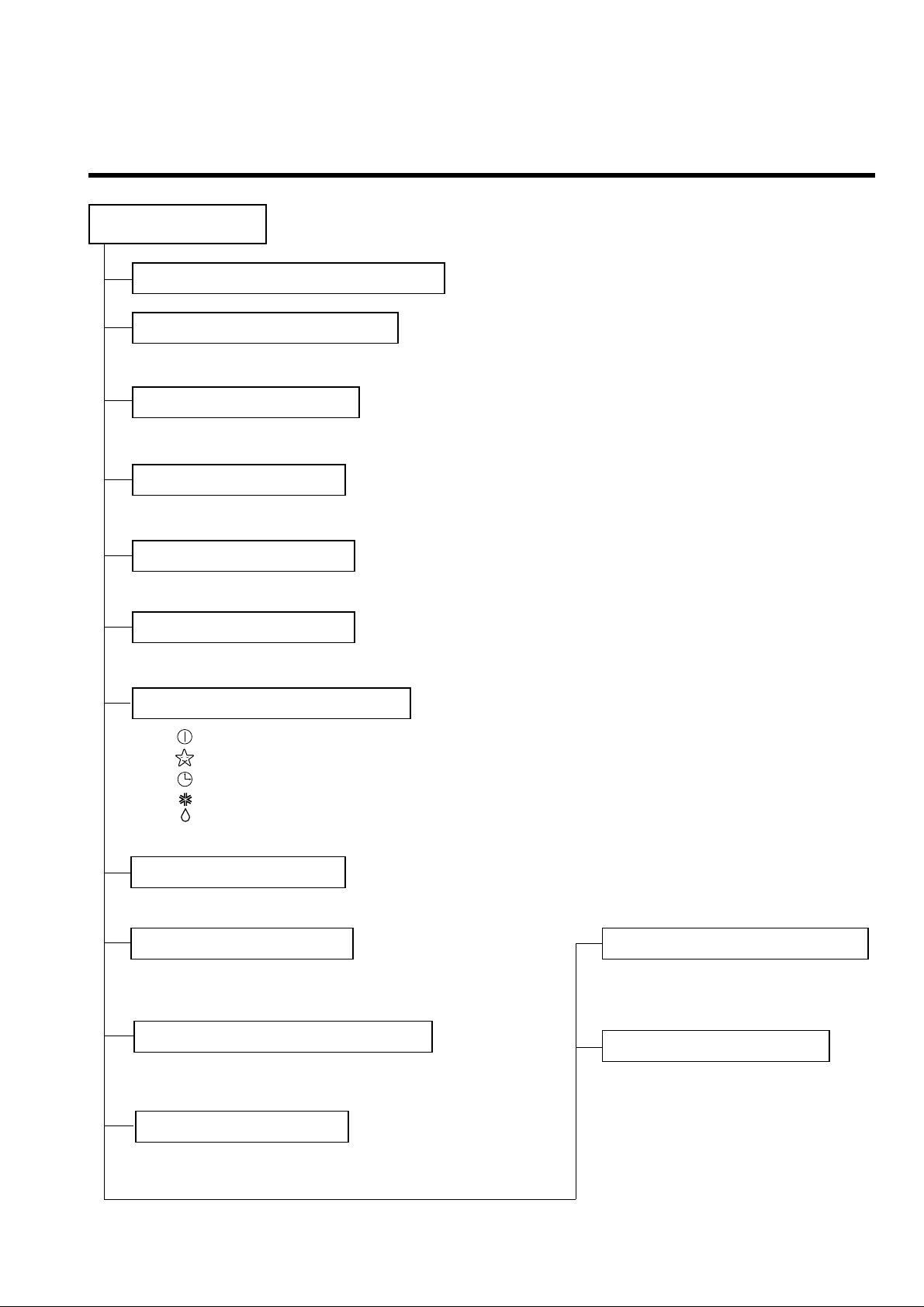
Functions
ƒU Room temperature sensor. (THERMISTOR)
ƒU Maintains the room temperature in accordance with the Setting Temp.
ƒU Indoor fan is delayed for 5 sec at the starting.
ƒU Restarting is inhibited for approx. 3 minutes.
ƒU High, Med, Low
--- Lights up in operation
--- Lights up in Sleep Mode
--- Lights up in Timer Mode
--- Lights up in Deice Mode (for Heating Model)
OUTDOOR --- Lights up in compressor operation (for Cooling Model)
ƒU Intermittent operation of fan at low speed.
ƒU The fan is switched to low(Cooling), med(Heating) speed.
ƒU The unit will be stopped after 1, 2, 3, 4, 5, 6, 7 hours.
ƒU The fan is switched to intermittent or irregular operation
ƒU
The fan speed is automatically switched from high to low speed.
ƒU The louver can be set at the desired position or swing
up and down automatically.
Indoor Unit
Operation ON/OFF by Remote controller
Sensing the Room Temperature
Room temperature control
Starting Current Control
Time Delay Safety Control
Indoor Fan Speed Control
Operation indication Lamps (LED)
Soft Dry Operation Mode
ƒU Both the indoor and outdoor fan
stops during deicing.
ƒU The indoor fan stops until the
evaporator piping temperature
will be reached at 28¡ .
Sleep Mode Auto Control
Natural Air Control by CHAOS Logic
Airflow Direction Control
ƒ¡3ƒ¡
Deice (defrost) control (Heating)
Hot-start Control (Heating)
Page 4
ƒ¡4ƒ¡
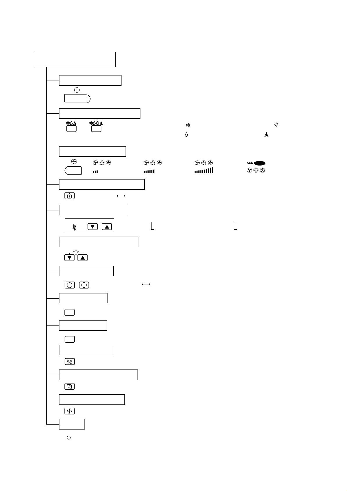
Remote Controller
Operation ON/OFF
Reset
Operation Mode Selection
Fan Speed Selection
Room Temperature Display
Temperature Setting
Setting the Time or Time
Timer Selection
Timer Setting
Timer Cancel
Sleep Operation
Airflow Direction Control
(Cooling
model only)
(Heating
model only)
TEMPERATURE
LOW HIGH
(Low) (Med) (High) (CHAOS)
Cooling Operation Mode.( )
Soft Dry Operation Mode.( ) Auto Operation Mode.( )
Heating Operation Mode.( )
CHAO
S
ON
OFF
SET
CANCEL
Fan Operation Mode
RESET
: High:39°C LOW:11°C
: Cooling
Down to 20°C
Up to 30°C
: Heating
Down to 16°C
Up to 30°C
: OFF, ON, OFF ON
: Cancel Sleep Mode, Timer ON or Timer OFF.
: 1, 2, 3, 4, 5, 6, 7, Off Timer
: Cooling Model Only
Page 5
ƒ¡5ƒ¡
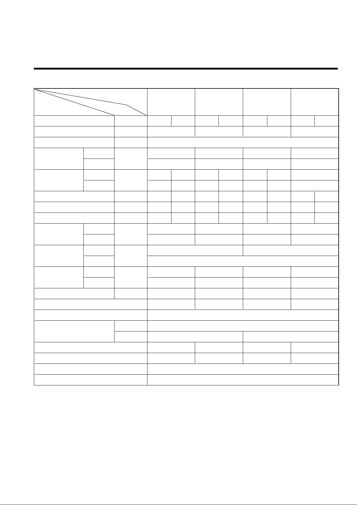
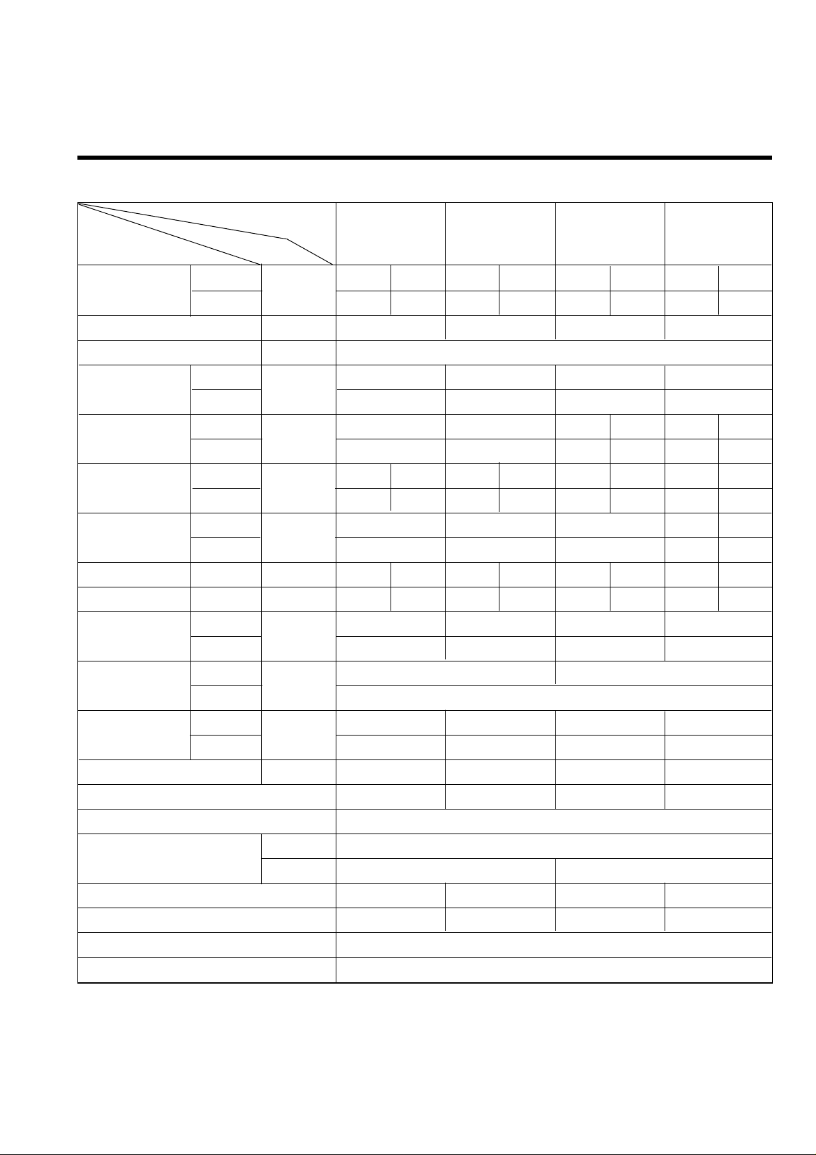
Product Specifications (Cooling Only)
Model Name
Item Unit
Cooling Capacity BTU/h 7,200 7,300 8,400 8,500 8,800 9,000 12,000 12,000
Moisture Removal §⁄/h 1.0 1.2 1.2 1.2
Power Source §j, V, Hz 1§j220-240V, 50Hz
Indoor 4.6 5.3 7.3 8.9
Outdoor 25 25 25 25
Indoor 35 36 37 38 36 37 38
Outdoor 46 47 47 48 47 48 49
Input W 690 715 890 900 730 750 1,180 1,180
Running Current A 3.2 3.2 4.0 3.9 3.4 3.3 5.8 5.4
E.E.R. BTU/h-W 10.4 10.2 9.44 9.44 12.0 12.0 10.17 10.17
Indoor 8 8 10 15
Outdoor 25 25 25 25
Indoor 790¡¿230¡¿142 880¡¿302¡¿183
Outdoor 660¡¿540¡¿260
Indoor 7 7 9.5 9.5
Outdoor 29 29 29 30
Refrigerant (R-22) g 560 490 780 700
Airflow Direction Control (Up & Down) § § § §
Remocon Type L.C.D Wireless
Liquid 1/4" (6.35)
Gas 3/8" (9.52) 1/2"(12.7)
Sleeping Operation § § § §
Drain Hose § § § §
Connecting Cable 1.0mm
2
Power Cord 1.0mm
2
Air Circulation
Noise Level
m3/min
dB (A)¡ 3
Service Valve
Motor Output
Dimensions
(W¡¿H¡¿D)
Net. Weight
W
mm
kg
LS-P0760CL LS-P0960CL LS-S0960CL LS-S1260CL
SPEC. AT 220/240V
Page 6
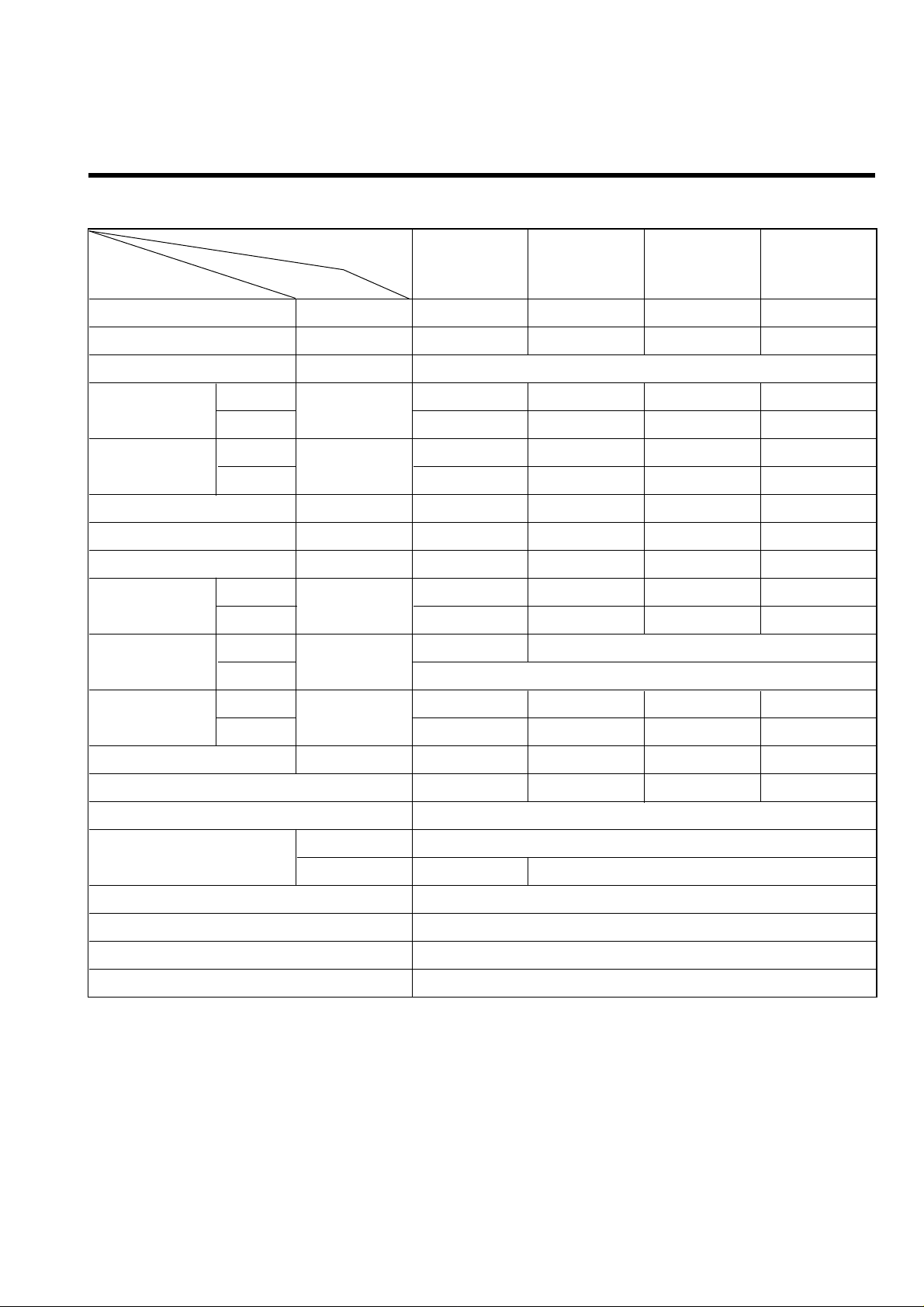
ƒ¡6ƒ¡
Model Name
Item Unit
Cooling Capacity BTU/h(kcal/h) 7,500(1,900) 11,000(2,772) 13,300(3,350) 14,000(3,550)
Moisture Removal §⁄/h 1.2 2.3 2.3 2.5
Power Source §j, V, Hz 1Ø, 220~V, 60Hz
Indoor 5.5 9.0 9.0 10.1
Outdoor 23 24 24 27
Indoor 36 39 39 39
Outdoor 47 49 49 50
Input W 710 1,050 1,378 1,500
Running Current A 3.3 4.9 6.3 6.9
E.E.R. BTU/h-W 10.6 10.5 9.7 9.3
Indoor 4.5 19.8 19.8 19.8
Outdoor 20 30 30 35
Indoor 790¡¿230¡¿142 880¡¿302¡¿183
Outdoor 660¡¿540¡¿260
Indoor 6 9.5 9.5 9.5
Outdoor 29 31.5 33.5 31.5
Refrigerant (R-22) g 600 710 980 750
Airflow Direction Control (Up & Down) § § § §
Remocon Type L.C.D Wireless
Liquid 1/4" (6.35)
Gas 3/8" (9.52) 1/2" (12.7)
Sleeping Operation §
Drain Hose §
Connecting Cable 1.0mm
2
Power Cord 1.0mm
2
Air Circulation
Noise Level
m3/min
dB (A)¡ 3
Service Valve
Motor Output
Dimensions
(W¡¿H¡¿D)
Net. Weight
W
mm
kg
LS-P0820CL LS-S1120CL LS-S1420CL LS-S1421CL
SPEC. AT 220V
Page 7
ƒ¡7ƒ¡
Product Specifications (Cooling & Heating)
Model Name
Item Unit
Cooling 7,000 7,000 8,400 8,500 9,400 9,500 11,700 12,000
Heating 7,300 7,500 9,400 9,500 10,200 10,500 12,600 13,000
Moisture Removal §⁄/h 1.3 1.17 1.2 1.2
Power Source §j, V, Hz 1§j220-240V, 50Hz
Indoor 5.3 6.3 7.6 8.9
Outdoor 24 25 25 25
Indoor 36 38 36 37 37 38
Outdoor 47 49 47 48 48 49
Cooling 710 720 910 940 940 950 1,210 1,250
Heating 730 740 940 990 900 950 1,160 1,230
Cooling 3.1 4.5 4.5 6.4 6.2
Heating 3.3 4.5 4.5 6.2 6.0
E.E.R. Cooling BTU/h¡⁄w 9.86 9.7 9.23 9.0 10.0 10.0 9.7 9.6
C.O.P Heating W/W 2.93 2.97 2.93 2.81 3.32 3.2 3.2 3.1
Indoor 8 8 10 15
Outdoor 25 25 25 25
Indoor 790¡¿230¡¿142 880¡¿302¡¿183
Outdoor 660¡¿540¡¿260
Indoor 7 7 9.5 9.5
Outdoor 30 31 31 33
Refrigerant (R-22) g 600 540 1,020 1,150
Airflow Direction Control (Up & Down) § § § §
Remocon Type L.C.D Wireless
Liquid 1/4" (6.35)
Gas 3/8" (9.52) 1/2"(12.7)
Sleeping Operation § § § §
Drain Hose § § § §
Connecting Cable 1.0mm
2
Power Cord 1.0mm
2
Air Circulation
Noise Level
Input
Running
Current
Capacity BTU/h
Service Valve
Motor Output
Dimensions
(W¡¿H¡¿D)
Net. Weight
m3/min
dB (A)¡ 3
W
A
W
mm
kg
LS-P0760HL LS-P0960HL LS-S0960HL LS-S1260HL
SPEC. AT 220/240V
Page 8
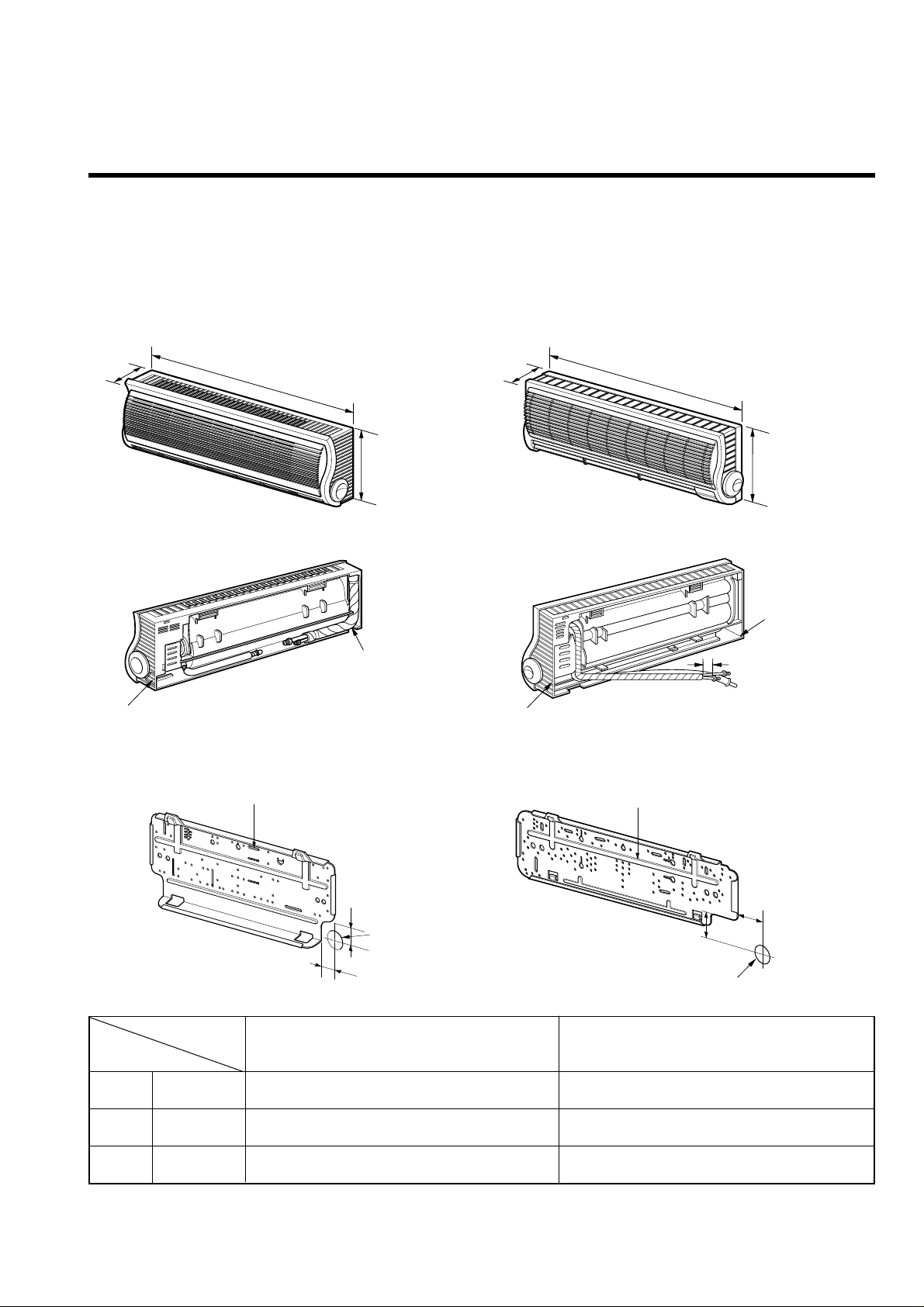
Dimensions
(1) Indoor Unit
ƒ¡8ƒ¡
W
D
H
Installation plate
45
70
Hole for piping
50
Tubing hole cover
Tubing hole cover
W
D
H
Installation plate
Hole for piping
Tubing hole cover
Tubing hole cover
20
50
MODEL
DIM
W mm 790 880
H mm 230 302
D mm 142 183
LS-P0760CL/P0760HL/P0820CL
LS-P0960CL/P0960HL
LS-S0960CL/S0960HL/S1120CL
LS-S1260CL/S1260HL/S1420CL/S1421CL
LS-P0760CL/P0760HL
LS-P0820CL
LS-P0960CL/P0960HL
LS-S0960CL/S0960HL
LS-S1120CL
LS-S1260CL/S1260HL
LS-S1420CL/S1421CL
Page 9
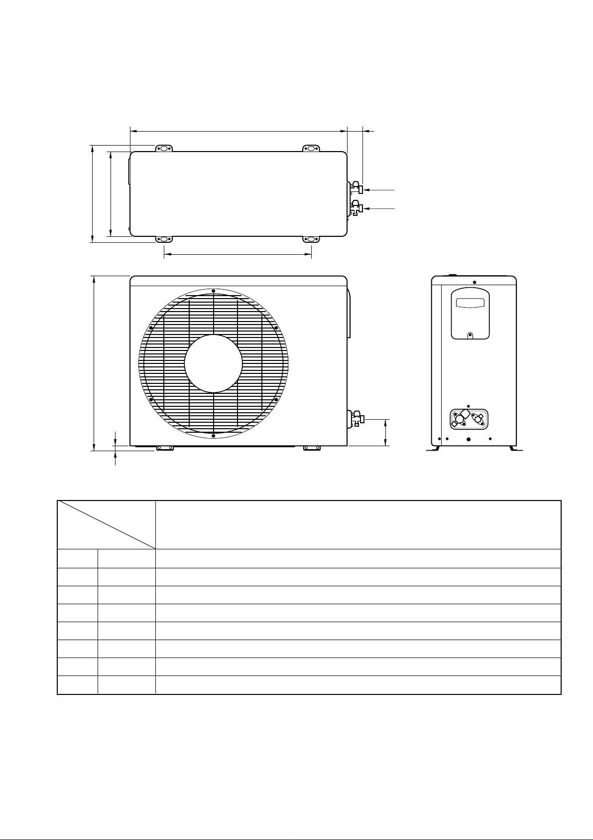
(2) Outdoor Unit
W L2
L3
L1
D
H
L4
L5
Liquid side (2-way valve)
Gas side (3-way valve)
MODEL
DIM
W mm 660
H mm 540
D mm 260
L1 mm 297
L2 mm 66
L3 mm 447
L4 mm 17
L5 mm 82
LS-P0760CL/P0760HL, LS-P0820CL, LS-P0960CL/P0960HL
LS-S0960CL/S0960HL, LS-S1120CL, LS-S1260CL/S1260HL
LS-S1420CL, LS-S1421CL
ƒ¡9ƒ¡
Page 10

Refrigeration Cycle Diagram
ƒ¡10ƒ¡
Pipe size(Diameter:§j)
MAX. Max
MODEL Piping length Elevation
Gas Liquid
(m) (m)
LS-P0760CL/P0760HL
LS-P0820CL 3/8" 1/4" 7 5
LS-P0960CL/P0960HL
LS-S0960CL/S0960HL
LS-S1120CL
LS-S1260CL/S1260HL
LS-S1420CL/S1421CL
1/2" 1/4" 7 5
INDOOR UNIT OUTDOOR UNIT
HEAT
EXCHANGE
(EVAPORATOR)
LIQUID SIDE
2-WAY VALVE
GAS SIDE
3-WAY VALVE
CAPILLARY TUBE
ACCUMU
LATOR
COMPRESSOR
HEAT
EXCHANGE
(CONDENSOR)
REVERSING
VALVE
(Heating Model Only)
COOLING
HEATING
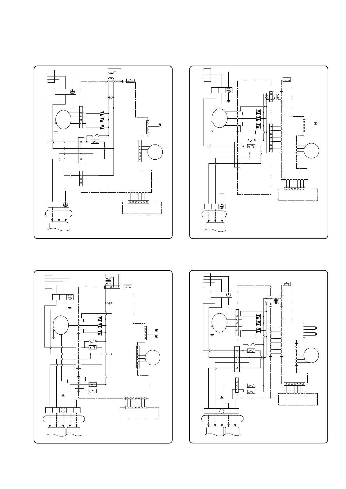
Page 11
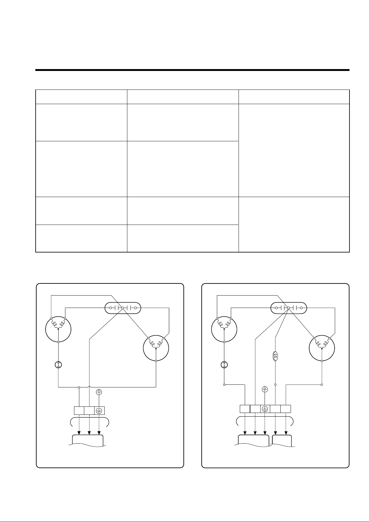
Wiring Diagram
ƒ¡11ƒ¡
F
CH
BL
R S
C
COMP
FAN
MOTOR
BL
CAPACITOR
RD
TO INDOOR UNIT
OUTDOOR WIRING DIAGRAM
RD
BR
OLP
BR
YL
PILLAR
TERMINAL
BL
3854AR2262F
1(L) 2(N)
1
GN/YL
BL
BR
BLACK
GN/YL
BL
BR
F
CH
BL
R S
C
COMP
FAN
MOTOR
BL
CAPACITOR
RD
TO INDOOR UNIT
OUTDOOR WIRING DIAGRAM
RD
BR
OLP
YL
PILLAR
TERMINAL
BL
3854AR2262E
1(L) 2(N)
GN/YL
1
GN/YL
BL
BR
3 4
BK
BK
2
RD
BL
BR
REVERSING
VALVE
RD
BK
3
BR
BLACK GRAY
MODEL INDOOR UNIT OUTDOOR UNIT
LS-P0760CL
LS-P0820CL
LS-P0960CL
LS-S0960CL
LS-S1120CL
LS-S1260CL
LS-S1420CL
LS-S1421CL
LS-P0760HL
LS-P0960HL
LS-S0960HL
LS-S1260HL
¤Ø
¤Œ
¤º
¤
¤
¤Ł
¤ ¤Ł
Page 12
ƒ¡12ƒ¡
BLACK
BL
BR
GN/YL
BR BL
GN/YL
GN/YL
POWER
BR BL
BL
OR
BR
YL
CN-FAN
SSR-L
SSR-M
SSR-H
CN-TRANS
CN-TH
CN-UP/DOWN
CN-DISP
THERMISTOR
MAIN PCB
ASM
DISPLAY PCB ASM
INDOOR WIRING DIAGRAM
3854AR2262D
GN/YL
TO OUTDOOR UNIT
PILLAR
TERMINAL
CN-4WAY
CN-POWER
RY-COMP
FUSE T2A
2
1
3
4
BR BL
TRANS
FORMER
FORCED
OPERATION
SWITCH
SH-CAPA
RD
MOTOR
1(L)
2(N)
STEP
MOTOR
RD
1(L) 2(N)
BLACK
BL
BR
GN/YL
BR BL
GN/YL
GN/YL
POWER
BR BL
BL
OR
BR
YL
RD
CN-FAN
SSR-L
SSR-M
SSR-H
SH-CAPA
AC PCB
ASM
CN-TRANS
CN-TH
CN-AC/DC
CN-UP/DOWN
CN-DISP
THERMISTOR
DC PCB
ASM
DISPLAY PCB ASM
INDOOR WIRING DIAGRAM
3854AR2262B
GN/YL
TO OUTDOOR UNIT
PILLAR
TERMINAL
RY-COMP
FUSE T2A
2
1
3
4
BR BL
TRANS
FORMER
FORCED
OPERATION
SWITCH
MOTOR
STEP
MOTOR
1(L)2(N)
1(L)
2(N)
¤Ø ¤Œ
BLACK
BL
BR
RD
BK
GN/YL
GRAY
BR BL
GN/YL
GN/YL
POWER
BR BL
BL
OR
BR
YL
CN-FAN
SSR-L
SSR-M
SSR-H
CN-TRANS
CN-TH
CN-UP/DOWN
CN-DISP
THERMISTOR
MAIN PCB
ASM
INDOOR WIRING DIAGRAM
3854AR2262C
GN/YL
BK RD
TO OUTDOOR UNIT
RY-FAN
PILLAR
TERMINAL
RY-4WAY
CN-4WAY
CN-POWER
RY-COMP
FUSE T2A
2
1
3
4
BR
BL
TRANS
FORMER
FORCED
OPERATION
SWITCH
SH-CAPA
RD
MOTOR
STEP
MOTOR
DISPLAY PCB ASM
RD
1(L) 2(L)
1(L)
2(N)
3 4
BLACK
BL
BR
RD
BK
GN/YL
GRAY
BR BL
GN/YL
GN/YL
POWER
BR BL
BL
OR
BR
YL
RD
CN-FAN
SSR-L
SSR-M
SSR-H
SH-CAPA
AC PCB
ASM
CN-TRANS
CN-TH
CN-AC/DC
CN-UP/DOWN
CN-DISP
THERMISTOR
DC PCB
ASM
DISPLAY PCB ASM
INDOOR WIRING DIAGRAM
3854AR2262A
GN/YL
TO OUTDOOR UNIT
RY-FAN
PILLAR
TERMINAL
RY-4WAY
CN-POWER
RY-COMP
FUSE T2A
2
1
3
4
BR BL
TRANS
FORMER
FORCED
OPERATION
SWITCH
MOTOR
STEP
MOTOR
BK RD
CN-4WAY
1(L) 2(L)
1(L)
2(N)
43
¤º ¤
Page 13
Operation Details
(1) The function of main control
1. Time Delay Safety Control
ƒU3min¡ƒ The compressor is ceased for 3minutes to balance the pressure in the refrigeration cycle.
(Protection of compressor)
ƒU2sec¡ƒ The indoor fan is ceased for 2sec. to prevent relay noise.
(Protection of fan relay and micro chip)
ƒU30sec¡ƒThe 4-way valve is ceased for 30sec. to prevent the refrigerant-gas abnormal noise when the Heating
operation is OFF or switched to the other operation mode.
2. Airflow Direction Control
ƒU This function is to swing the louver up and down automatically and to set it at the desired position.
ƒU The procedure is as the following.
1st ; Press the ON/OFF Button to operate the product.
2nd ; Press the Airflow Direction Control Button to swing the louver up and down automatically.
3rd ; Repress the Airflow Direction Control Button to set the louver as the desired position.
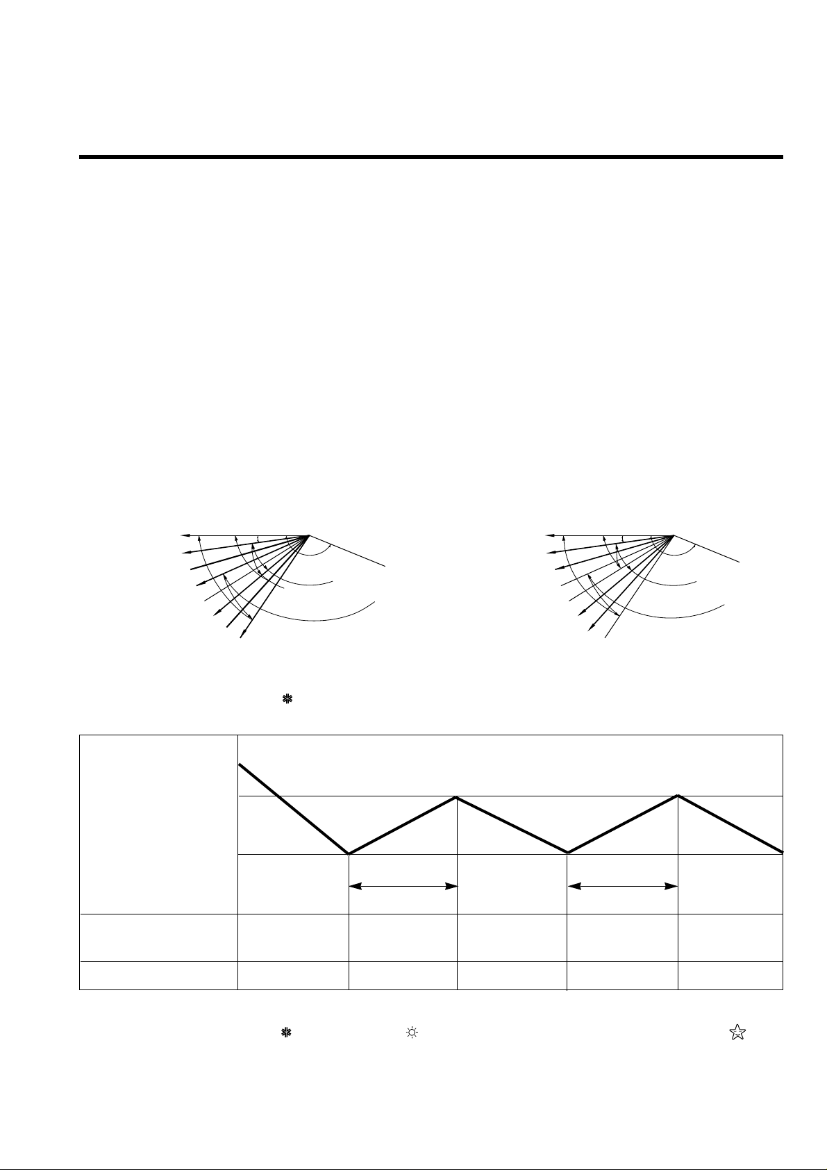
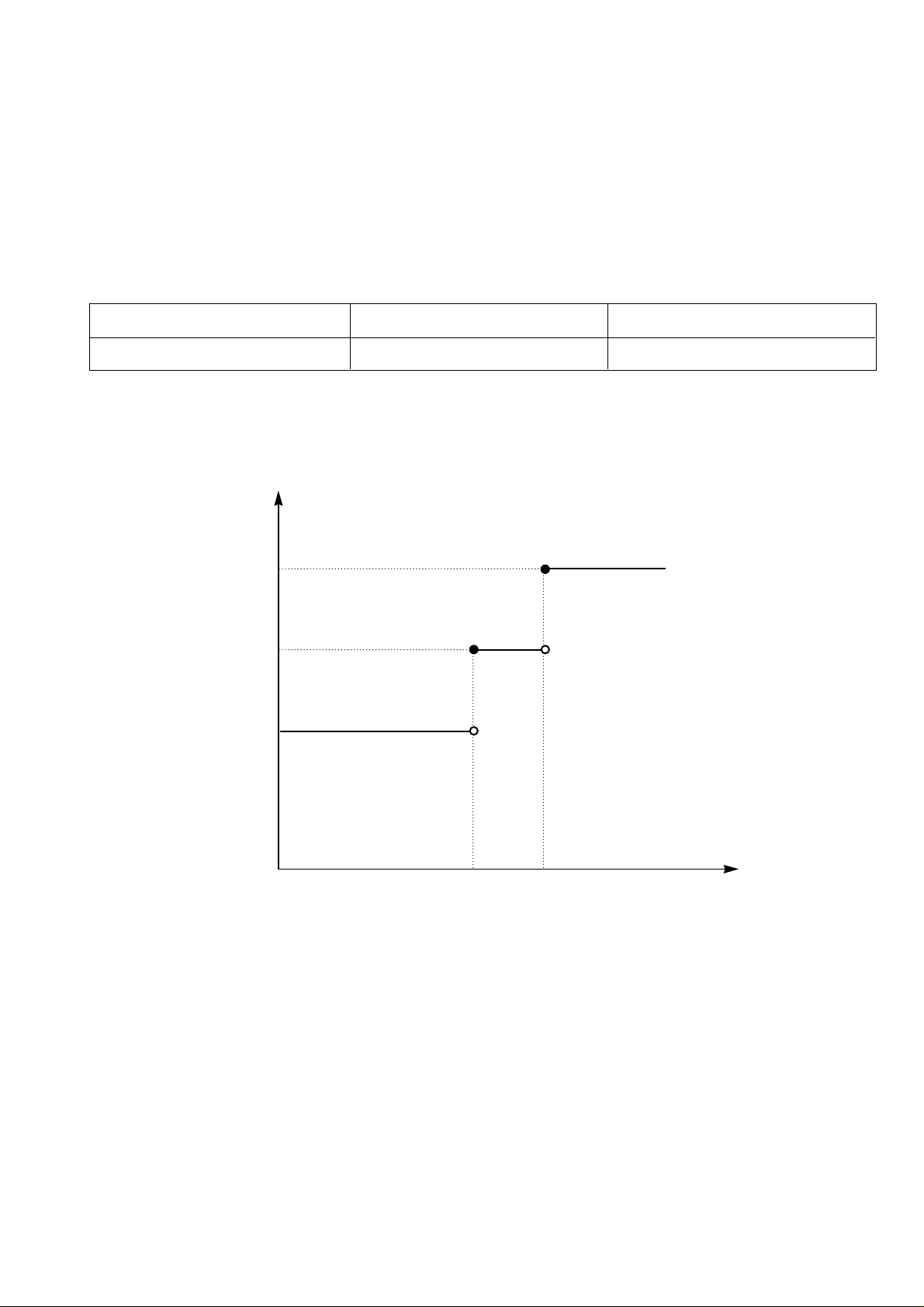
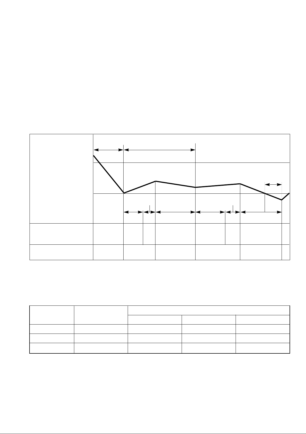
3. Cooling Mode Operation
ƒU When selecting the Cooling( ) Mode Operation, the unit will operate according to the setting by the remote
controller and the operation diagram is as following
4. Cooling or Heating Mode with Sleep Mode Auto Operation
ƒU When selecting the Cooling( ) or the Heating( ) combined with the Sleep Mode Auto Operation( ), the
operation diagram is as following.
ƒ¡13ƒ¡
Horizontal 0
1
2
3
4
5
6
7
8
Setting point:
Setting range for:
(Close)
7°
110°
Cooling
Approx. 28°
Heating
Approx. 28°
Cooling
Heating
Heating
Cooling
Horizontal 0
1
2
3
4
5
6
7
8
Setting point:
Setting range for:
(Close)
8°
150°
Cooling
Approx. 32°
Heating
Approx. 32°
Cooling
Heating
Heating
Cooling
LS-S0960CL/S0960HL, LS-S1120CL
LS-S1260CL/S1260HL
LS-S1420CL, LS-S1421CL
LS-P0760CL/P0760HL, LS-P0820CL
LS-P0960CL/P0960HL
Intake Air temp.
COMP. ON
(SET TEMP.+0.5¡ )
COMP. OFF
(SET TEMP. -0.5¡ ) More than More than
3 minutes 3 minutes
Selecting Selecting Selecting
fan speed fan speed fan speed
COMPRESSOR ON OFF ON OFF ON
INDOOR FAN Low Low
¢”
¢”
Page 14
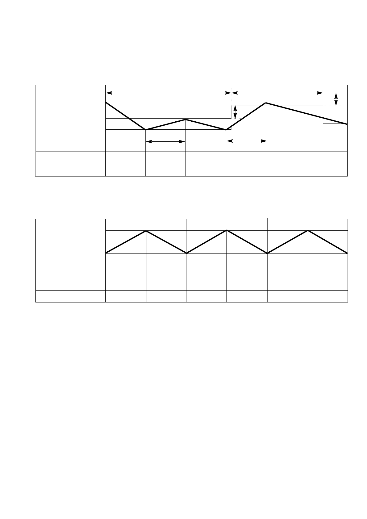
¡Æ Cooling Mode with the Sleep Mode
ƒU The setting temperature will be raised by 1¡ 30minutes later and by 2¡ 1 hour later.
ƒU The operation will be stopped after 1, 2, 3, 4, 5, 6, 7 hours.
¡Æ Heating Mode with the Sleep Mode.
ƒU The operation will be stopped after 1, 2, 3, 4, 5, 6, 7 hours.
ƒ¡14ƒ¡
Intake Air temp.
COMP. ON
(SET TEMP.+0.5¡ )
COMP. OFF
(SET TEMP. -0.5¡ ) Morethan More than
3 minutes 3 minutes
INDOOR FAN Low Low Low Low Low
COMPRESSOR ON OFF ON OFF ON
Delay 3 minutes
30 minutes 30 minutes
1¡
1¡
Setting Temp. +3¡
(Compressor OFF)
Setting Temp.
(Compressor ON)
Indoor Fan Med. Med. Med. Med. Med. Med.
Compressor ON OFF ON OFF ON OFF
¢”
¢”
¢”
¢”
Page 15
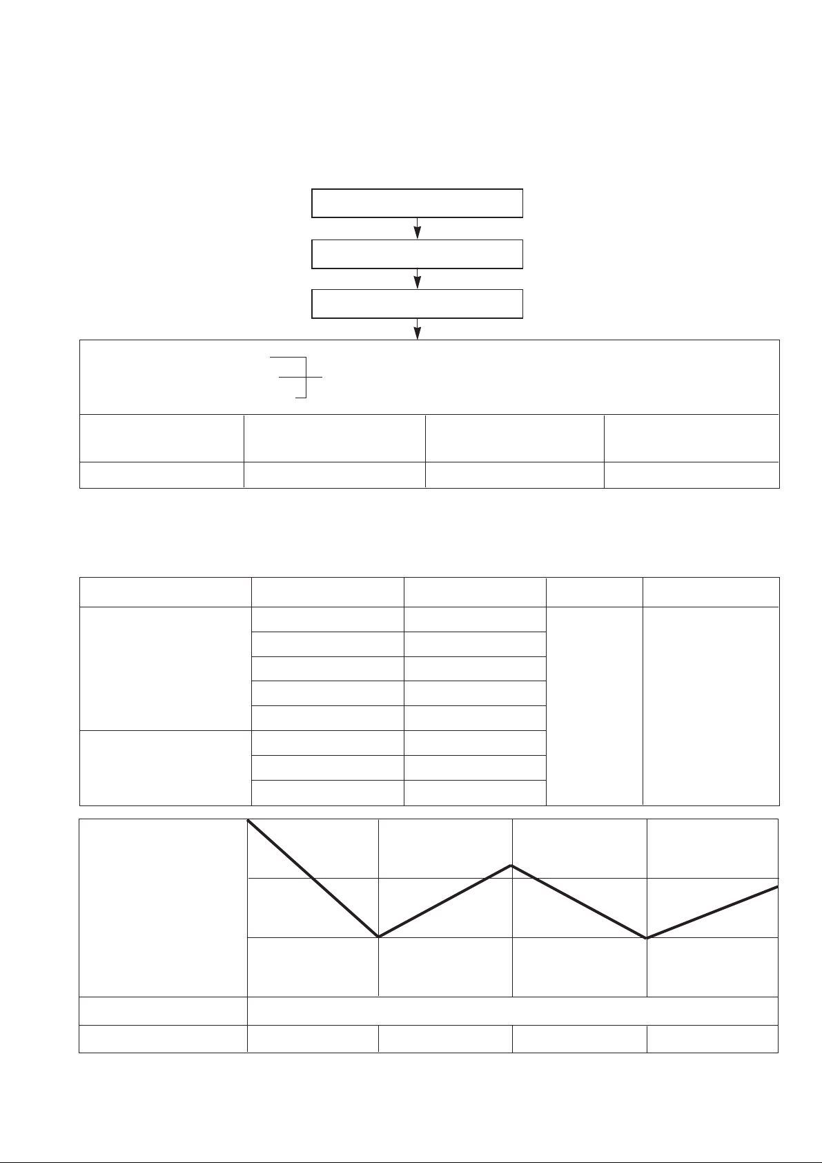
5. Auto Operation
ƒU The operation procedure is as following.
ƒNIf initial mode is decided, that mode is continued without the room temperature changing.
ƒƒUU
Auto Operation for Cooling.
ƒ¡15ƒ¡
Press Start/Stop Button
Select Auto Operation Mode
Check the Room temperature
Operation mode
Indoor fan speed are automatically decided by Fuzzy rule.
Setting temperature
Intake-air
temperature
Operation Mode Heating Soft Dry Cooling
Operation Condition Intake-air Temperature Setting temperature Fan speed Air Direction Control
Over 26°C 25°C
Over 24°C~below 26°C Intake air -1.0°C
Over 22°C~below 24°C Intake air -0.5°C
Over 20°C~below 22°C Intake air temperature
below 20°C 20°C
Over 20°C~below 30°C Fuzzy control
below 20°C 20°C
Over 30°C 30°C
below 21¡
below
24¡
~
Over 24¡
Over
21¡
When Auto Operation
initial start
When Switch to
Auto Operation
Controlled
by Fuzzy logic
1/f rhythm
Intake-Air temp
Setting Temp. +0.5°C
(Compressor OFF)
Setting Temp.-0.5°C
(Compressor ON)
Indoor Fan
Compressor ON OFF ON OFF
Fuzzy Speed
¢”
¢”
Page 16
ƒƒUU
Auto Operation for Soft Dry.
The Setting temperature will be set to the same that of the current intake-air temperature.
- Compressor ON temperature; Setting temperature +1°C
- Compressor OFF temperature; Setting temperature -0.5°C
ƒƒUU
Auto Operation for Heating.
ƒ¡16ƒ¡
Intake Air temp. below 20°C over 20°C~below 21°C
Setting temp. 20°C Intake air Temperature +0.5°C
21°C
20°C
20°C
Intake-Air temp.
Setting temp.
20.5°C
21°C
Page 17
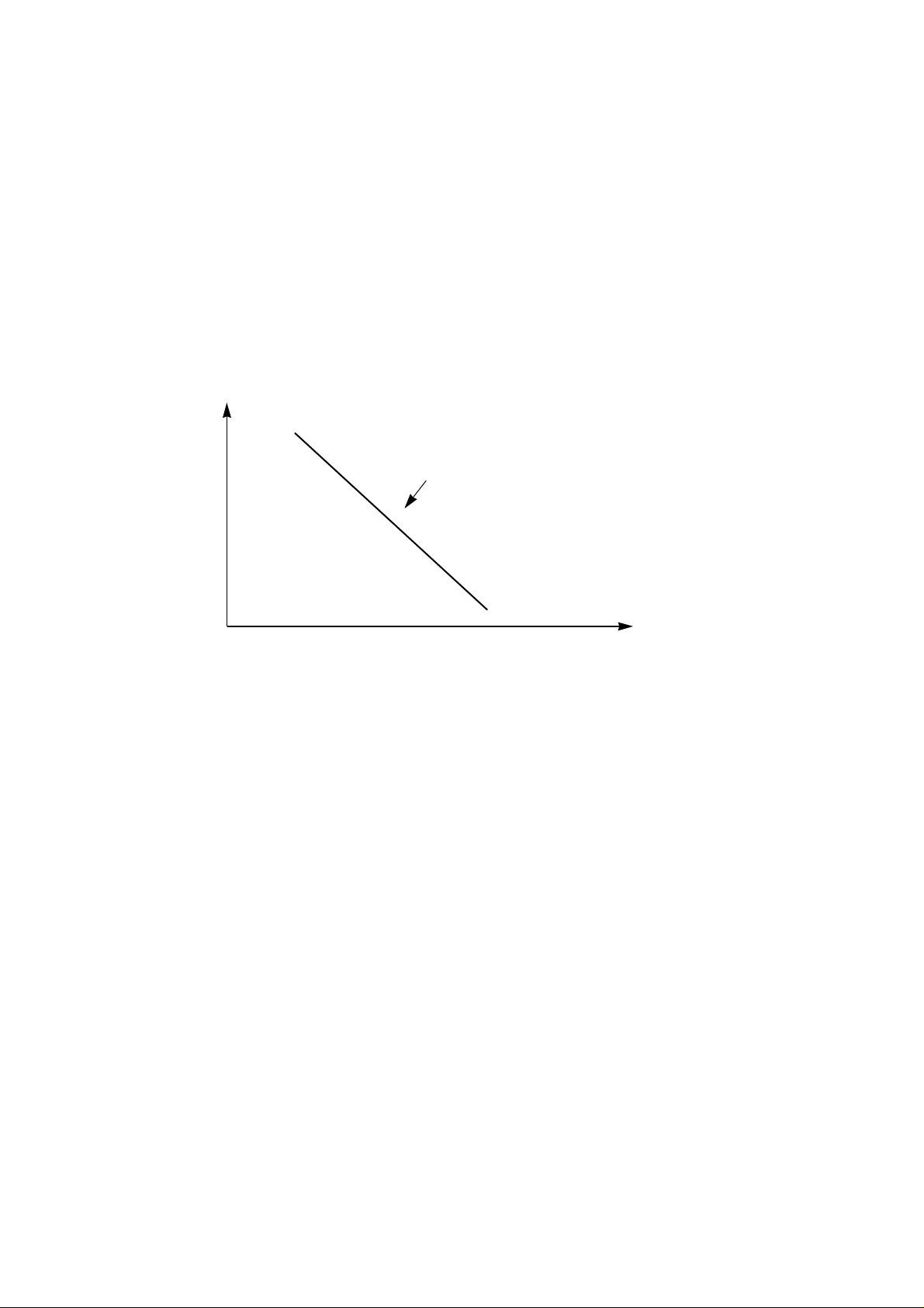
6. Natural Wind by CHAOS logic
There are common rules in the irregular changes amid the breeze of highlands and valleys, the sound of
streams, the songs of birds in the forest and brain waves of relaxation.
Mmm... the breath-taking and touchy feeling of wind from the deep mountains and dark valleys.
Through analysis in its chaos simulator, Goldstar has successfully created such a feeling of freshness and
serenity by analyzing the frequency of natural wind.
Generally natural wind has the following character (frequency-Magnitude), for example dark vally, sea, mountain wind.
So as to make a similar Natural wind function, Indoor fan speed is shifted to high from low or reversely in
according to the CHAOS logic.
ƒ¡17ƒ¡
Magnitude
frequency(Hz)
natural wind function
Page 18
7. Heating Mode Operation
The unit will operate according to the setting by the remote controller and the operation diagram is shown as
following.
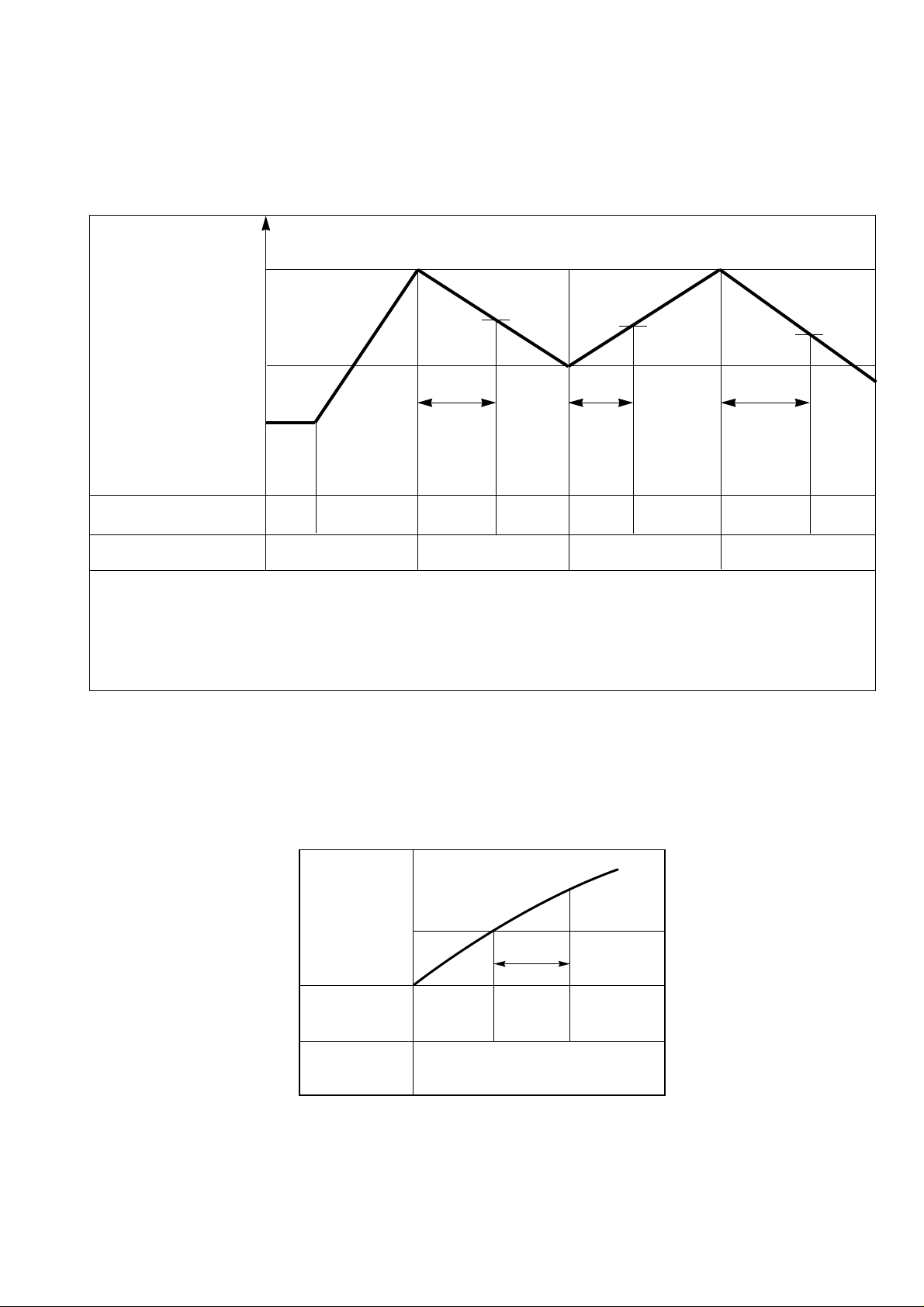
8. Hot-Start Control
ƒU The indoor fan stops until the evaporator piping temperature will be reached at 28¡ . (BY TEMPERATURE)
ƒU The operation diagram is as following.
ƒ¡18ƒ¡
Intake Air temp.
Setting temp.+3¡
(Compressor OFF)
Setting temp.
(Compressor ON)
INDOOR FAN Low OFF Low Low OFF
COMPRESSOR ON OFF ON OFF
ƒU A point; The indoor pipe temperature to be 35°C
The indoor fan operates minimum 10sec. even if falls lower than 35°C
ƒU B point; The indoor pipe temperature to be 35°C
The indoor fan operates minimum 10sec. even if falls lower than 35°C
Selecting fan
speed
HOT
START
OFF
Selecting fan
speed
minimum
10sec.
A A
minimum
10sec.
minimum
10sec.
B
¢”
¢”
PIPING
TEMP 28°C
60 sec.
COMPRESSOR
INDOOR
FAN
LOWOFF
SELECTING
FAN SPEED
ON
(HOT-START BY TEMPERATURE)
Page 19
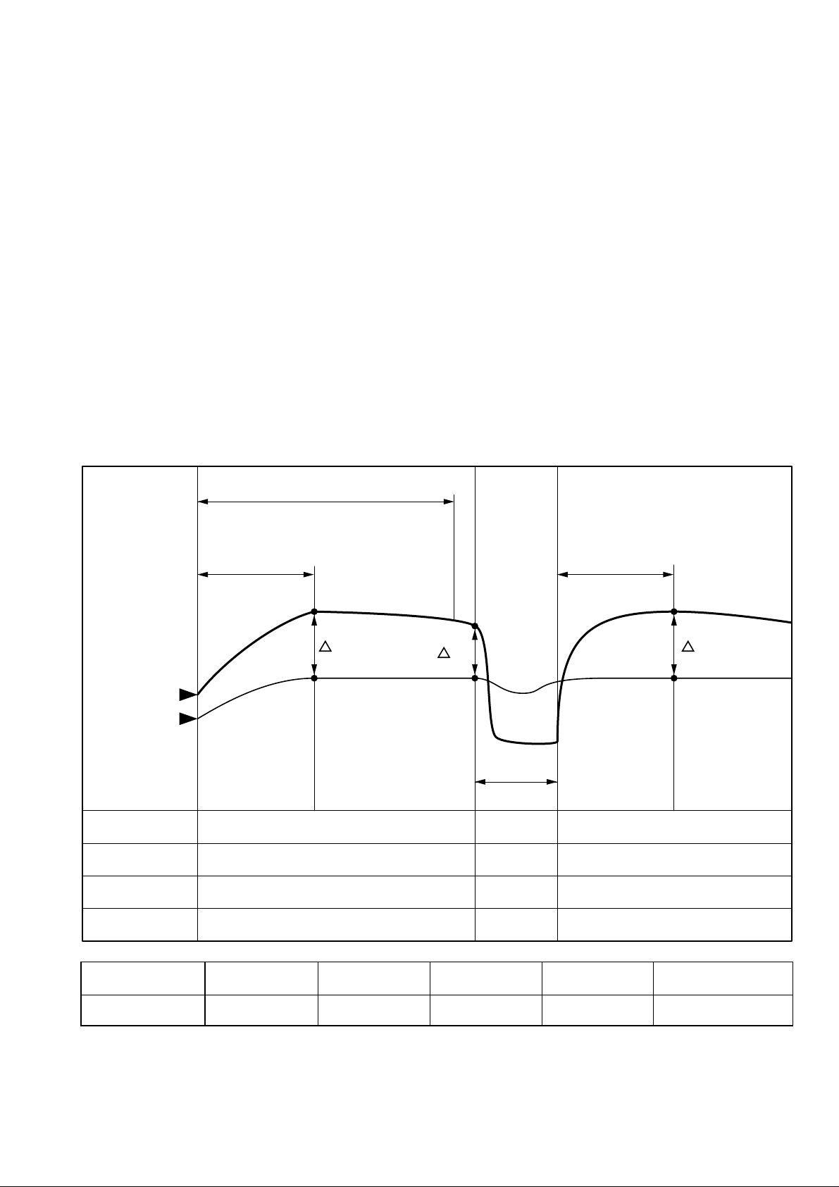
9. Deice Control
ƒU Deicing operation is controlled by timer and sensing the indoor pipe temperature.
ƒU Deicing operation checks the indoor pipe temperature and Intake-air temperature at 25 minutes and 60 min-
utes on starting of heating operation, and discriminates by temperature difference.
ƒU When the heating operation passed 25 minutes, the temperature (¡ T1=TE1–TR1) is checked and memorized
with checking the indoor pipe temperture (TE1) and the indoor Intake-air temperature (TR1).
ƒU When the heating operation passed 60 minutes, deicing operation checks the indoor pipe temperature (TE2)
and the indoor Intake-air temperature (TR2), and checks the temperature difference (¡ T2=TE2–TR2) and the
temperature difference ¡ Td(=¡ T1–¡ T2) of ¡ T1, ¡ T2.
If the temperature difference (¡ Td) become more than the option temperature, deicing operation starts.
ƒU At that time, deicing operation time is decided.
ƒU The deicing operation time stops after deicing operation started.
ƒU If deicing operation start, above heating operation time is reset, so if deicing operation is finished, the heating
operation time is recounted.
ƒU The deicinig time and the operation diagram are as following.
ƒ¡19ƒ¡
60 minutes
Heating
25 MINS
Heating
TE1
TR1
TE2
TR2
TR1
TE1
Heating
25 MINS
Deicing
Pipe Temp.
Intake Air
Temp.
T1
T2
T1
TEMP °C
INDOOR FAN
OUTDOOR FAN
COMPRESSOR
4WAY VALVE
ON
ON
ON
ON
OFF
OFF
ON
OFF
ON After HOT-START finished
ON
ON
ON
Td (=T1– T2) Over 3.5°C 3.0~3.5°C 2.5~3.0°C 2.0~2.5°C below 2.0°C
Deicing Time 12mins 11mins 10mins 9mins Heating Operation
Page 20
10. Soft Dry Operation.
ƒU During Soft Dry Operation, the compressor ON temperature is the setting temperature plus 1¡ , the compres-
sor OFF temperature is the setting temperature minus 0.5¡
ƒU When the room temperature rises over the compressor ON temperature, the operation mode is switched to the
cooling mode.
ƒU When the room temperature falls between the compressor ON temperature and OFF temperature, the opera-
tion mode is switched to the Soft Dry Operation.
In this temperature range, 10min. Dry Operation, 5.5min operation OFF, 1.5min. only fan operation repeat. During 10min Dry operation, even if the room temperature falls below compressor OFF temperature, 10min(MAX)
Compressor ON from starting of Dry operation which includes 4 min. Compressor ON operation below the
comperssor OFF temperature.
ƒU In micom dehumidify mode, control of fan speed is as following.
11. Forced operation
ƒU If you lose wireless remote controller, you can operate the unit with forced operation switch.
ƒU The standand conditions are as following.
ƒ¡20ƒ¡
ROOM TEMP.
SETTING TEMP.+1°C
(COMP. ON)
SETTING TEMP.
(COMP. OFF)
INDOOR FAN OFF
LOW
LOW OFF LOW LOW
COMPRESSOR ON OFF ON OFF ON
Selecting
fan speed
2 minutes
5.5 minutes
maximum
4 minutes
1 minutes
1.5 minutes
10 minutes
maximum
10minutes
Operation
Cooling
Dry operation
Heat pump Model
Room Temp¡ˆ 24°C 21°C ¡´Room Temp£…24°C Room Temp £…21°C
Operation Mode Cooling Cooling Soft Dry Heating
FAN Speed High High Low High
Setting Temp. 24°C 24°C Room Temp. 22°C
Cooling Model
¢”
¢”
Page 21
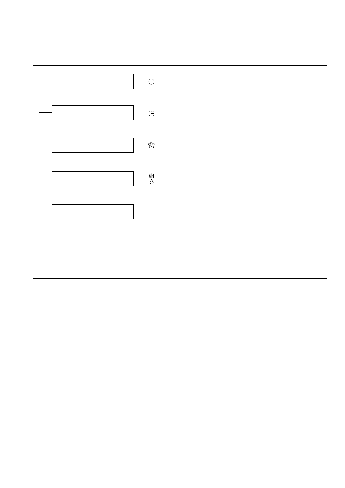
Display Function
• Cooling, Soft Dry, Heating
• Timer Mode
• Sleep Mode
• Hot-start, Deice
Self-diagnosis Function
1. Protection of the evaporator pipe from frosting
If the temperature of the indoor pipe is below 0°C after 7 mins from starting the compressor, the compressor
and the outdoor fan is stopped, and then after 3 mins delay of the compressor and the temperature of the
indoor pipe is over 7°C, the compressor and the outdoor fan is reoperated.
2. Thermistor Cut Off or Short
Cut Off/Short : Blinks on and off the operation mode LED. (0.5 sec ON/3 sec OFF)
Operation Indicator
Timer Indicator
Sleep Timer Indicator
Deice Indicator
: Heating Model only
Compressor On Indicator
: Cooling Model only OUTDOOR
ƒ¡21ƒ¡
Page 22
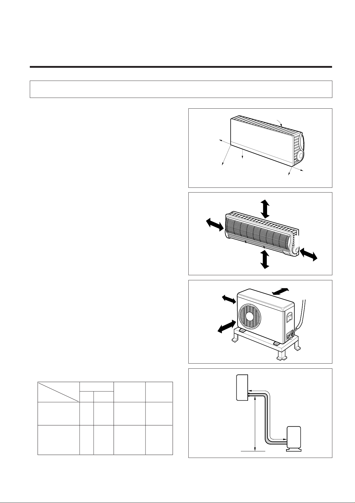
Installation
1) Selection of the best location
1. Indoor unit.
• There should not be any heat source or steam near
the unit.
• There should not be any obstacles to prevent the air
circulation.
• A place where air circulation in the room will be
good.
• A place where drainage can be easily obtained.
• A place where noise prevention is taken into consideration.
• Do not install the unit near the door way.
• Ensure the spaces indicated by arrows from the
wall, ceiling, fence, or other obstacles.
2. Outdoor unit.
• If an awning is built over the unit to prevent direct
sunlight or rain exposure, be careful that heat radiation from the condenser is not restricted.
• There should not be any animals or plants which
could affected by hot air discharged.
• Ensure the spaces indicated by arrows from the
wall, ceiling, fence, or other obstacles.
3. Piping length and the elevation.
Ringt
Rear right
Down right
Rear left
left
Front
Pipe size Max. piping Max.
GAS LIQUID A(m) B(m)
3/8" 1/4" 7 5
1/2" 1/4" 7 5
1. Installation of indoor, Outdoor unit
ƒ¡22ƒ¡
LS-P0760CL/P0760HL
LS-P0820CL
LS-P0960CL/P0960HL
LS-S0960CL/S0960HL
LS-S1120CL
LS-S1260CL/S1260HL
LS-S1420CL/S1421CL
length elevation
More than
5cm
More than 5cm
More than
5cm
More than eye-level
More than
10cm
More than
70cm
Indoor unit
More than
10cm
A
B
Outdoor unit
Page 23

2) Indoor unit installation
The mounting wall should be strong and solid enough
to prevent it from the vibration.
1. Mount the installation plate on the wall with
four Type "A" screws.
• Always mount the installation plate horizontally by
aligning the marking-off line with using the thread
and a level.
LS-P0760CL/P0760HL, LS-P0820CL
LS-P0960CL/P0960HL
• To remove the installation plate, pull the two '¡ '
marked portion of bottom of chassis and pull the
installation plate out of chassis.
2. Drill the piping hole with 70mm dia. Hole-core
drill.
• Line according to the arrows marked on lower the
left and the right side of the installation plate.
The meeting point of the extended line is the center
of the hole.
• Drill the piping hole at either the right or the left and
the hole should be slightly slant to the outdoor side.
Installation Plate
Thread
Marking-off line
Weight
Type “A” screw
Left rear piping
ø70mm
ø70mm
50mm
20mm
20mm
80mm
LS-P0760CL/P0760HL, LS-P0820CL
LS-P0960CL/P0960HL
Right rear piping
WALL
5~7mm
Indoor Outdoor
LS-S0960CL/S0960HL, LS-S1120CL
LS-S1260CL/S1260HL, LS-S1420CL, LS-S1421CL
Left rear piping Right rear piping
Center Center
ø70mm ø70mm
The lower left and right side of installation Plate
ƒ¡23ƒ¡
££…… ££
æ
Page 24

1) Preparation of pipings
1. Cut the pipes and the cable.
• Use the accessory piping kit or the pipes purchased
locally.
• Measure the distance between the indoor and the
outdoor unit.
• Cut the pipes a little longer than measured distance.
• Cut the cable 1.5m longer than the length of pipe.
2. Remove burrs.
• Remove burrs from cut edges of pipes.
• Turn the pipe end toward down to avoid the metal
powder entering the pipe.
Caution:
If burrs are not removed, they may cause a gas leakage.
3. Flaring the pipes.
• Insert the flare nuts, mounted on the connection
ports of both indoor and outdoor unit, onto the copper pipes. Some refrigerant gas may leak, when the
flare nuts are removed from the indoor unit, as
some gas is charged to prevent the inside of the
pipe from rusting.
• Fit the copper pipe end into the Bar of flare tool
about 0.5~1.0mm higher. (See illustration).
• Flare the pipe ends.
4. Tape the flaring portion to protect it from the
dust or damages.
90°
Pipe cutter
Slanted Rough
"A";§j12.7mm(3/8")¡ 0.5mm
"A";§j9.52mm(
1
/2")¡ 1.0mm
"A";§j6.35mm(
1
/4")¡ 1.0mm
When properly flared, the internal surface flare
will evenly shine and be of even thickness. Since
the flare part comes into contact with the connectors, carefully check the flare finish.
= Improper flaring =
Inclined Surface
damaged
Cracked Uneven
thickness
2. Piping and Drainage of indoor unit
ƒ¡24ƒ¡
Pipe
Reamer
Point down
Bar
Copper pipe
Yoke
Bar
A
Handle
Cone
Page 25

2) Connection of pipings
(LS-S0960CL/S0960HL, LS-S1120CL, LS-S1260CL/S1260HL, LS-S1420CL, LS-S1421CL)
1. Remove the indoor tubing with Drain hose to the hole.
• Remove tubing holder and pull the tubing out of the chassis.
2. Refix the tubing holder into original position.
Tubing holder
Press1
Pull2
To remove the holder,
press the bottom of the
chassis near the holder
upwards and pull the tab
out of its hole.
For right rear piping
ƒ¡25ƒ¡
3. Route the tubing and the drain hose straight
backwards(see figure).
4. Insert the connecting cable into the indoor unit
through the piping hole.
• Do not connect the cable to the indoor unit.
• Make a small loop with the cable for easy connection later.
5. Tape the tubing, drain hose and the connecting
cable.
Outdoor
Piping
Indoor
Connecting cable
Taping
Indoor/outdoor
connecting cable
Connecting
cable
Gas side piping
Liquid side piping
Drain hose
Page 26

6. Indoor unit installation.
• Hook the indoor unit onto the upper portion of installation plate. (Engage the two hooks of the rear top
of the indoor unit with the upper edge of the installation plate.)
Ensure the hooks are properly seated on the installation plate by moving it in left and right.
7. Connecting the pipings to the indoor unit
• Align the center of the pipings and sufficiently tighten the flare nut with fingers.
• Finally, tighten the flare nut with torque wrench until
the wrench clicks.
Wrench tightening the flare nut with forque wrench,
ensure the direction for tightening follows the arrows
on the wrench.
8. Wrap the insulation material around the con-
necting portion.
Connecting
cable
Drain hose
Press the lower left and right side of the unit
against the installation Plate until the hooks
engages with their slots(sound click).
Indoor unit tubing
Flare nut Pipings
Torque wrench
Spanner
Pipe Size Torque
Liquid Side(1/4") 1.8Kg¡⁄m
Gas Side(1/2") 5.5Kg¡⁄m
ƒ¡26ƒ¡
Plastic Bands Insulation material
Wrap the insulation material around the connecting portion.
Page 27

3. Route the indoor tubing with the drain
hose to the piping hole as desired
position.
Outdoor
Piping
Indoor
Connecting cable
ƒ¡27ƒ¡
Tubing holder
Press1
Pull2
To remove the holder,
press the bottom of the
chassis near the holder
upwards and pull the tab
out of its hole.
For the left pipings
4. Insert the pipings and the connecting cable
into the piping hole.
5. Insert the connecting cable into the indoor unit.
• Do not connect the cable to the indoor unit.
• Make a small loop with the cable for easy connection later.
6. Tape the tubing, drain hose and the connecting
cable.
Taping
Indoor/outdoor
connecting cable
Connecting
cable
Gas side piping
Liquid side piping
Drain hose
Page 28

7. Indoor unit installation.
• Hook the indoor unit onto the upper portion of installation plate. (Engage the two hooks of the rear top
of the indoor unit with the upper edge of the installation plate.)
Ensure the hooks are properly seated on the installation plate by moving it in left and right.
8. Connecting the pipings to the indoor unit
• Align the center of the pipings and sufficiently tighten the flare nut with fingers.
• Finally, tighten the flare nut with torque wrench until
the wrench clicks.
Wrench tightening the flare nut with forque wrench,
ensure the direction for tightening follows the arrows
on the wrench.
9. Wrap the insulation material around the con-
necting portion.
Plastic Bands Insulation material
Wrap the insulation material around the connecting portion.
ƒ¡28ƒ¡
Connecting
cable
Drain hose
Press the lower left and right side of the unit
against the installation Plate until the hooks
engages with their slots(sound click).
Indoor unit tubing
Flare nut Pipings
Torque wrench
Spanner
Pipe Size Torque
Liquid Side(1/4") 1.8Kg¡⁄m
Gas Side(1/2") 5.5Kg¡⁄m
Gas Side(5/8") 6.5Kg¡⁄m
Page 29

10.Set the pipings and the connecting cable to the
back of the chassis with the tubing holder.
11. Indoor unit installation.
• Hook the indoor unit onto the upper portion of installation plate. (Engage the two hooks of the rear top
of the indoor unit with the upper edge of the installation plate.)
Ensure the hooks are properly seated on the installation plate by moving it in left and right.
Tubing holder
Taping
Piping
Drain hose
Hook
1
Push
2
Press the lower left and right side of the unit
against the installation Plate until the hooks
engages with their slots(sound click).
ƒ¡29ƒ¡
Connecting
cable
Drain hose
Page 30

2) Connection of Pipings
1. Remove the installation plate
• Pull the two '¡' marked portion of bottom of the chassis and pull the installation plate out of chassis.
2. Route the drain hose and the indoor tubing.
3. Insert the pipings, the connecting cables and
the drain pipe throught the piping hole on the
wall.
4. Connect the pipings and the indoor tubing, and
drain hose and drain pipe.
• Don't connect the cable to the indoor unit.
• Wrap the insulation material around the connecting
portion.
• Glue up the connection portion of drain hose and
drain pipe.
ƒ¡30ƒ¡
For right rear piping
Pipe Size Torque
Liquid Side (1/4") 1.8kg·m
Gas Side (3/8") 4.2kg·m
(LS-P0760CL/P0760HL, LS-P0820CL, LS-P0960CL/P0960HL)
Installation plate
pull
pull
Outdoor
Piping
Indoor
Connecting cable & Drain pipe
Indoor unit tubing
Spanner
Plastic Bands Insulation material
Drain Hose
Flare nut Pipings
Torque wrench
Drain Pipe
Adhevsive
Page 31

ƒ¡31ƒ¡
5. Bend the tubing as shown in the figure and
bind the pipings, the connecting cables and the
drain hose altogether.
• Make a small loop for easy connection later.
6. Wrap the tubing, the drain hose and the connecting cable
7. Indoor unit installation
• Hook the indoor unit onto the upper position of installation plate. (Engage the two hooks of the rear top of
the indoor unit with the upper edge of the installation
plate.)
Insure the hooks are properly seated on the installation plate by moving it in left and right.
CAUTION : Take care to arrange the pipings, drain
hose and cables as the feature 6 page for
inserting it into the indoor unit and mount
the indoor unit on the installation plate.
Connecting cable
Drain hose
Press the lower left and right side of the unit
against the Installation Plate until the hooks
engages with their slots (sound click).
Gas side piping
Liquid side piping
Drain hose
Connecting
cable
Loop
Tape
Page 32

ƒ¡32ƒ¡
3. Insert the connecting cables, the drain pipe
and connecting pipings throught the piping
hole on the wall.
4. Connect connecting pipings and indoor tubing,
and the drain hose and the drain pipe and
place the drain pipe into the chassis.
• Don't connect the cableto the indoor unit.
• Make a small loop for easy connection later.
• Glue up the connection portion of drain hose and
drain pipe.
5. Bend the drain hose as shown in the figure and
bind the drain hose, the pipings and the connecting cables altogether.
Outdoor
Indoor
Connecting Cable
Drain Pipe
Drain Hose
Connecting Piping
For left rear pipings
Pipe Size Torque
Liquid Side (1/4") 1.8kg·m
Gas Side (3/8") 4.2kg·m
Indoor unit tubing
Flare nut Pipings
Spanner
Drain Hose
Torque wrench
Drain Pipe
Adhevsive
Loop
Page 33

ƒ¡33ƒ¡
6. Wrap the insulation material around the connecting portion.
CAUTION : Take care to arrange the pipings, drain
hose and cables as the feature 6 page for
inserting it into the indoor unit and mount
the indoor unit on the installation plate.
7. Wrap the tubing, the drain hose and the connecting cable with tape.
8. Indoor unit installation
• Hook the indoor unit onto the upper position of installation plate. (Engage the two hooks of the rear top of
the indoor unit with the upper edge of the installation
plate.)
Insure the hooks are properly seated on the installation plate by moving it in left and right.
Indoor/outdoor
connecting cable
Taping
Gas side piping
Liquid side piping
Drain hose
Connecting
cable
Press the lower left and right side of the unit
against the Installation Plate until the hooks
engages with their slots (sound click).
Plastic Bands Insulation material
Wrap the insulation material around the connecting portion.
Connecting cable
Drain hose
Page 34

1) Connecting the piping to the Oudoor
unit.
1. Align the center of the pipings and sufficiently
tighten the flare nut with fingers.
2. Finally, tighten the flare nut with torque wrench
until the wrench clicks.
• When tightening the flare nut with touque wrench,
ensure the direction for tightening follows the arrow
on the wrench.
2) Connecting of the cable
1. Remove the cover control from the unit by
lossening the screw.
Connect the wires to the terminals onthe con-
trol board individually as the following.
1) Cooling only type
2. Secure the cable onto the control board with
the holder (clamper).
3. Refix the cover control to the original position
with the screw.
ƒNThe connecting cable for installation of indoor and
outdoor unit must be approved by TüV standard or
equivalent.
Pipe Size Torque
Liquid Side(1/4") 1.8Kg¡⁄m
Gas Side(3/8") 4.2Kg¡⁄m
Gas Side(1/2") 5.5Kg¡⁄m
Outdoor unit
Liquid side piping
(Smaller Dia)
Gas side
piping
(Bigger Dia)
Torque wrench
Terminal block
(Pillar terminal)
Outdoor unit
Over 5mm
Holder for
connecting
cable
Connecting
cable
Cover control
BROWN BLUE
GREEN/YELLOW
1(L) 2(N)
BLACK GRAY
1(L) 2(N) 3 4
BLACK GRAY
BROWN BLUE G/Y BLACK RED
Terminals on the outdoor unit
Terminals on the indoor unit
Terminals on the outdoor unit
1(L) 2(N)
1(L) 2(N) 3 4
Terminals on the indoor unit
BROWN BLUE G/Y BLACK RED
Color of Wires
2) Cooling & Heating type
Color of Wires
Color of Wires
3. Connecting Pipings and the cable to Outdoor unit
ƒ¡34ƒ¡
Page 35

1) Checking the Drainage
1. Remove the Grille from the cabinet.
• Set the up-and-down air direction louver to open
position(horizontally) by finger pressure.
• Remove the screw caps and the securing screws.
• To remove the Grille, pull lower the left and right
side of the grille toward you (slightly tilted) and lift it
straight upward.
2. Check the drainage.
• Pour a glass of water on the evaporator.
• Ensure if water flows drain hose of indoor unit.
Pull the right and the left side.
Screw
Screw cap
Evaporator
4. Checking the Drainage and Connecting the cable to Indoor unit
ƒ¡35ƒ¡
Page 36

2) Connect the cable to the indoor unit
1. Connect the wires to the terminals on the con-
trol board individually according to the outdoor
unit connection.
• Ensure the color of wires of outdoor unit and the ter-
minal No.s are the same to the indoor's respectively.
1) Cooling only type
• Secure the cable onto the control board with the
holder(clamper).
2. Attach the Grille onto the cabinet
• Grasp lower the left and right side of the Grille and
engage two tabs on the top in side edge of the grille
with two slots on the cabinet's top front edge.
• press the grille toward the cabinet until it will be
back into place.
• Secure the grille to the cabinet with two screws.
Connecting
cable
ƒ¡36ƒ¡
BROWN BLUE
GREEN/YELLOW
1(L) 2(N)
BLACK GRAY
1(L) 2(N) 3 4
BLACK GRAY
BROWN BLUE G/Y BLACK RED
Terminals on the outdoor unit
Terminals on the indoor unit
Terminals on the outdoor unit
1(L) 2(N)
1(L) 2(N) 3 4
Terminals on the indoor unit
BROWN BLUE G/Y BLACK RED
Color of Wires
2) Cooling & Heating type
Color of Wires
Color of Wires
Page 37

3) Form the pipings
1. Wrap the connecting portion of indoor unit with
the lnsulation material and secure it with two
plastic Bands (for the right pipings).
• If you want to connect an additional drain hose, the
end of the drain-outlet should keep distance from
the ground.(Do not dip it into water, and fix it on the
wall to avoid swinging in the wind.)
2. Tape the pipings, drain hose and Connecting
Cable from down to up.
3. Form the pipings gathered by taping along the
exterior wall and fix it onto the wall by saddle
or equivalent.
2. Tape the pipings and Connecting Cable from
down to up.
3. Form the pipings gathered by taping along the
exterior wall and the Trap is required to prevent
the room from entering the water.
4. Fix the pipings onto the wall by saddle or
equivalent.
Seal a small opening
around the pipings with
aum type sealer.
Taping
Drain
hose
Pipings
Connecting
cable
Plastic Band
Trap is required to prevent the electrical
parts from entering the water.
In case of the Oudoor unit to be installed
below the Indoor unit
In case of the Outdoor unit to be installed
upper position of the Indoor unit
ƒ¡37ƒ¡
Seal a small opening
around the pipings with
gum type sealer.
Trap
Page 38

1) Air purging
The air which contains a moisture is remaining in the
refrigeration cycle may cause a malfunction on the
compressor.
1. Remove the caps from the 2-way and 3-way
valves.
2. Remove the service-port cap from the 3-way valve.
3. To open the valve, turn the valve stem of 2-way
valve counter-clockwise approx. 90° and hold it
there for five seconds, then close it.
4. Check a gas-leakage of the connection portion of
the pipings.
• For the left pipings, refer page 26.
• For more details, refer page 45(2-way 3-way valve).
ƒNCAUTION:
Do not leak the gas in the air during Air purging
with vacumm pump as possible as you can.
2-way valve
(Open)
3-way valve
(Close)
Terminal block
(pillar terminal)
Cover control
To indoor unit
Liquid side
Gas side
Cap
Hexagonal wrench
Service port cap
5. To open 2-way valve again, turn the valve stem
counter-clockwise until it stops.
6. To purge the air, push the pin on the service port
of 3-way valve for three seconds with a hexagonal
wrench and set it free for one minute.
ƒU Repeat the operation three times.
ƒU Re-tighten the connecting portion with wrench.
No leakage found
Result
leakage found
leakage ceased
leakage ceased
leakage persists
¤
¤
¤
¤
Repair
5. Air Purging
ƒ¡38ƒ¡
7. Set the both 2-way and 3-way valves to open position with the hexagonal wrench for the unit operation.
Page 39

8. Checking a gas leakage.
(1)Connect the manifold gauge to the service port of
3-way valve.
Measure the pressure.
(2)Keep it for 5-10 minutes.
Ensure if the pressure indicated on the gauge is
as same as that of measured at first time.
Chiuso
Indoor unit
Liquid side
Closed
Closed
CLOSE
CLOSE
Outdoor unit
Gas side
NOTE:
The additional gas for air purging has been charged in the outdoor unit.
However, if the flare connections have not been done correctly and there gas leaks, a gas cylinder and the
charge set will be needed.
ƒNCAUTION:
Do not leak the gas in the air during Air purging with vacumm pump as possible as you can.
ƒ¡39ƒ¡
Page 40

1) Connection of power supply
1. Connect the power supply cord to independent
power supply.
2. Prepare the remote control.
• Insert two batteries provided.
Remove the cover from the back of the remote control.
• Slide the cover according to the arrow directon.
• Insert the two batteries.
(Two "R03" or "AAA" dry-cell batteries or equivalent).
• Be sure that the (+) and (-) directions are correct.
• Be sure that both batteries are new.
Re-attach the cover.
• Slide it back into position.
3. Operate the unit at cooling operation mode for
fitteen minutes or more.
• Anchor the outdoor unit with a bolt and nut (ø10cm)
tightly and horizontally on a concrete or rigid mount.
• When installing on the wall, roof or rooftop, anchor
the mounting base securely with a nail or wire
assuming the influence of wind and earthquake.
• In the case when the vibration of the unit is con-
veyed to the house, settle the unit with an antivibration rubber.
2) Evaluation of the performance
1. Measure the temperature of the intake and discharge air.
2. Ensure the difference between the intake temperature and the discharge one is more than
8°C.
Tubing connection
discharge air
Settlement of Outdoor Unit
6. Test running
ƒ¡40ƒ¡
Page 41

Operation
(1) Name and Function-Remote Control (Cooling Models)
Signal transmitter.
Transmits the signals
to the room air conditioner.
ƒ¡41ƒ¡
Remote Controller
1
2
6
7
10
11
13
14
12
9
3
4
5
8
TIME TIME
ON OFF
a.m.
p.m.
a.m.
p.m.
Hr.
ON
OFF
SET
CANCEL
RESET
ROOM AIR CONDITIONER
REMOTE CONTROL
15
CHAO
S
°
C
L
H
⁄A Operation Display
Displays the operation conditions.
⁄B Start/Stop Button
Operation start when this button is pressed, and
stops when the button is pressed again.
⁄C Operation Mode Selection Button
Used to select the type of operation mode.
ƒUCooling Operation Mode.
ƒUSoft Dry Operation Mode.
ƒUAuto Operation Mode.
⁄D Sleep Mode Auto Button
For Sleep Mode Auto Operation.
⁄E ON Timer Button
Used to set the time of starting operation.
⁄F Timer Set Button
Press to set the timer operation.
⁄G Timer CANCEL Button
Press to cancel the timer operation.
⁄H Indoor Fan Speed Selector
⁄I OFF Timer Button
Used to set the time of stopping operation.
⁄J Time Setting Button
⁄K Room Temperature Setting Button
Used to adjust the temperature.
⁄L Room Temperature
⁄M Airflow Direction Control Button
Press to set the desired airflow direction.
⁄N Reset Button
⁄O Fan Operation Button.
Used to operate the indoor fan only.
Page 42

(2) Name and Function-Remote Control (Heat Pump Models)
Signal transmitter.
Transmits the signals
to the room air conditioner.
ƒ¡42ƒ¡
Remote Controller
⁄A Operation Display
Displays the operation conditions.
⁄B Start/Stop Button
Operation start when this button is pressed, and
stops when the button is pressed again.
⁄C Operation Mode Selection Button
Used to select the type of operation mode.
ƒUCooling Operation Mode.
ƒUSoft Dry Operation Mode.
ƒUHeating Operation Mode.
ƒUAuto Operation Mode.
⁄D Sleep Mode Auto Button
For Sleep Mode Auto Operation.
⁄E ON Timer Button
Used to set the time of starting operation.
⁄F Timer Set Button
Press to set the timer operation.
⁄G Timer CANCEL Button
Press to cancel the timer operation.
⁄H Indoor Fan Speed Selector
⁄I OFF Timer Button
Used to set the time of stopping operation.
⁄J Time Setting Button
⁄K Room Temperature Setting Button
Used to adjust the temperature.
⁄L Room Temperature
⁄M Airflow Direction Control Button
Press to set the desired airflow direction.
⁄N Reset Button
CHAO
TIME TIME
ON OFF
a.m.
p.m.
8
5
ON
4
3
OFF
9
S
H
L
°
C
a.m.
p.m.
Hr.
1
2
SET
CANCEL
6
7
10
11
12
14
RESET
ROOM AIR CONDITIONER
REMOTE CONTROL
13
Page 43

Disassembly of the parts (Indoor unit)
Warning :
Disconnect the unit from power supply before making
any checks.
Be sure the power switch is set to “OFF”.
To remove the Grille from the Chassis.
• Set the up-and-down air discharge louver to open
position (horizontally) by finger pressure.
• Open the screw caps upward and remove the
securing screws.
• To remove the Grille, pull the lower left and right
side of the grille toward you (Slightly tilted) and lift it
straight upward.
1. To remove the sensor, housing connect, earth
conductor & step motor conductor with sensor
holder, Motor, Evaporator & P.C.B.
Up-and-down air direction louver
Screw
Screw cap
ƒ¡43ƒ¡
Page 44

2. To remove the Control Box.
• Remove 2 or 4 securing screws.
• Pull the control box out from the chassis
carefully.
3. To remove the Discharge Grille.
• Remove the securing screw.
• Pull the discharge grille out from the chassis
carefully.
4. To remove the Evaporator.
ƒ¡44ƒ¡
Page 45

• Unhook the tab on the left inside edge of the
chassis by pressing it outwards and at the same
time, slightly pull the evaporator until the tab is
clear of the end-plate.
• Remove the evaporator from the chassis
carefully.
• Unhook the tab on the right inside of the chassis
at the same time, slightly pull the evaporator
toward you until the tab is clear of the slot.
5. To remove the Cross-Flow Fan.
• Loosen the screw securing the cross-flow fan to
the fan motor (do not remove).
• Pull the left end of the cros-flow fan with the selfaligning bearing out the groove.
• Remove the cross-flow fan by sliding it out from
the shaft of fan motor.
6. To remove the Fan Motor.
• Pick it up from the groove. (Do not remove a
black rubber as a spacer).
Tab
Pull
Evaporator
End Plate
evaporator
Evaporator
Pull
Tab
Fan motor
Screw
Cross-flow fan
Cross-flow fan
Bearing
ƒ¡45ƒ¡
Page 46

2-way, 3-way Valve
2-way Valve (Liquid Side) 3-way Valve (Gas Side)
Shaft position Shaft position Service port
Closed Closed Closed
(with valve cap) (with valve cap) (with cap)
Open Closed Open
(counter-clockwise) (clockwise) (push-pin or with
vacumm pump)
Open Open Closed
(with valve cap) (with valve cap) (with cap)
Closed Open Open
(clockwise) (counter-clockwise) (connected manifold
gauge)
Open Open Open
(with charging
cylinder)
Open Open Open
(with charging
cylinder)
Open Open "
Open Open "
Works
Shipping
Air purging
(Installation)
Operation
Pumping down
(Transfering)
Evacuation
(Servicing)
Gas charging
(Servicing)
Pressure check
(Servicing)
Gas releasing
(Servicing)
1.
2.
3.
4.
5.
6.
Valve cap
Open position
Closed position
Pin
Service
port
Service
port cap
To outdoor unit
Flare nut
To
piping
connection
To outdoor unit
Hexagonal wrench (4mm)
Open position
Closed position
To
piping
connection
Flare nut
ƒ¡46ƒ¡
Page 47

1. Air purging
Required tools : hexagonal wrench, adjustable
wrench, torque wrenches, wrench to
hold the joints, and gas leak
detector.
The additional gas for air purging has been charged
in the outdoor unit.
However, if the flare connections have not been done
correctly and there gas leaks, a gas cylinder and the
charge set will be needed.
The air in the indoor unit and in the piping must be
purged. If air remains in the refrigeration pipes, it will
affect the compressor, reduce to cooling capacity, and
could lead to a malfunction.
• Procedure
(1) Recheck the piping connections.
(2) Open the valve stem of the 2-way valve
counterclockwise approximately 90°, wait 10
seconds, and then set it to closed position.
– Be sure to use a hexagonal wrench to operate
the valve stem.
(3) Check for gas leakage.
– Check the flare connections for gas leakage.
(4) Purge the air from the system.
– Set the 2-way valve to the open position and
remove the cap from the 3-way valve’s service
port.
– Using the hexagonal wrench to press the valve
core pin, discharge for three seconds and then
wait for one minute. Repeat this three times.
(5) Use torque wrench to tighten the service port
nut to a torque of 1.8kg.cm.
(6) Set the 3-way valve to the back seat.
(7) Mount the valve stem nuts to the 2-way and 3-
way valves.
(8) Check for gas leakage.
– At this time, especially check for gas leakage
from the 2-way and 3-way valve’s stem nuts,
and from the service port nut.
Caution
If gas leakage are discovered in step (3) above,
take the following mesures :
If the gas leaks stop when the piping connections
are tightened further, continue working from step (4).
If the gas leaks do not stop when the connections
are retightened, repair the location of the leak,
discharge all of the gas through the service port,
and then recharge with the specified amount of
gas from a gas cylinder.
Service port unt.
Be sure, using a torque wrench to tighten the service port nut (after using the service port), so that it prevents the
gas leakage from the refrigeration cycle.
* CAUTION : Do not leak the gas in the air during Air purging.
Liquid side
Outdoor unit
3-way
valve
Gas side
Indoor unit
2-way
valve
Open
Clsed
ƒ¡47ƒ¡
Page 48

2. Pumping down
• Procedure
(1) Confirm that both the 2-way and 3-way valves
are set to the open position.
– Remove the valve stem caps and confirm that
the valve stems are in the raised position.
– Be sure to use a hexagonal wrench to operate
the valve stems.
(2) Operate the unit for 10 to 15 minutes.
(3) Stop operation and wait for 3 minutes, then
connect the charge set to the service port of
the 3-way valve.
– Connect the charge hose with the push pin to
the service port.
(4) Air purging of the charge hose.
– Open the low-pressure valve on the charge set
slightly to air purge from the charge hose.
(5) Set the 2-way valve to the closed position.
(6) Operate the air conditioner at the cooling
cycle and stop it when the gauge indicates
1kg/cm2g.
(7) Immediately set the 3-way valve to the closed
position.
– Do this quickly so that the gauge ends up
indicating 3 to 5kg/cm2g.
(8) Disconnect the charge set, and mount the 2-
way and 3-way valve’s stem nuts and the
service port nut.
– Use torque wrench to tighten the service port
nut to a torque of 1.8 kg.m.
– Be sure to check for gas leakage.
Lo
Closed
Purge the air
Outdoor unit
Indoor unit
Liquid side
Gas side
CLOSE
Open
2-Way
valve
3-Way
valve
CLOSE
ƒ¡48ƒ¡
Page 49

1) Re-air purging
(Re-installation)
• Procedure
(1) Confirm that both the 2-way valve and the 3-
way valve are set to the closed position.
(2) Connect the charge set and a gas cylinder to
the service port of the 3-way valve.
– Leave the valve on the gas cylinder closed.
(3) Air purging.
– Open the valves on the gas cylinder and the
charge set. Purge the air by loosening the flare
nut on the 2-way valve approximately 45° for 3
seconds then closing it for 1 minute; repeat 3
times.
– After purging the air, use a torque wrench to
tighten the flare nut on the 2-way valve.
(4) Check for gas leakage.
– Check the flare connections for gas leakage.
(5) Discharge the refrigerant.
– Close the valve on the gas cylinder and
discharge the refrigerant until the gauge
indicates 3 to 5 kg/cm2g.
(6) Disconnect the charge set and the gas
cylinder, and set the 2-way and 3-way valves
to the open position.
– Be sure to use a hexagonal wrench to operate
the valve stems.
(7) Mount the valve stem nuts and the service
port nut.
– Use torque wrench to tighten the service port
nut to a torque of 1.8 kg.m.
– Be sure to check for gas leakage.
* CAUTION:
Do not leak the gas in the air during Air
Purging.
Lo
Closed
OPEN
Closed
Gas cylinder
R22
Outdoor unit
Indoor unit
Liquid side
Gas side
CLOSE
2-Way
valve
3-Way
valve
ƒ¡49ƒ¡
Page 50

2) Balance refrigerant of the 2-way, 3-way valves
(Gas leakage)
• Procedure
(1) Confirm that both the 2-way and 3-way valves
are set to the back seat.
(2) Connect the charge set to the 3-way valve’s
port.
– Leave the valve on the charge set closed.
– Connect the charge hose with the push pin to
the service port.
(3) Open the valve (Lo side) on the charge set
and discharge the refrigerant until the gauge
indicates 0 kg/cm2G.
– If there is no air in the refrigerant cycle (the
pressure when the air conditioner is not
running is higher than 1 kg/cm2G), discharge
the refrigerant until the gauge indicates 0.5 to 1
kg/cm2G. if this is the case, it will not be
necessary to apply a evacuatin.
– Discharge the refrigerant gradually; if it is
discharged too suddenly, the refrigeration oil
will also be discharged.
Lo
Open
Open
3-Way
valve
2-Way
valve
Gas side
CLOSEOPEN
Outdoor unit
Liquid side
Indoor unit
ƒ¡50ƒ¡
Page 51

3. Evacuation
(All amount of refrigerant leaked)
• Procedure
(1) Connect the vacuum pump to the charge set’s
center hose
(2) Evacuation for approximately one hour.
– Confirm that the gauge needle has moved
toward -76 cmHg (vacuum of 4 mmHg or less).
(3) Close the valve (Lo side) on the charge set,
turn off the vacuum pump, and confirm that
the gauge needle does not move (approximately 5 minutes after turning off the vacuum
pump).
(4) Disconnect the charge hose from the vacuum
pump.
– Vacuum pump oil.
If the vacuum pump oil becomes dirty or
depleted, replenish as needed.
Lo
Open
Open
Vacuum pump
2-Way
valve
Outdoor unit
Liquid side
Indoor unit
Gas side
3-Way
valve
CLOSE
OPEN
ƒ¡51ƒ¡
Page 52

4. Gas Charging
(After Evacuation)
• Procedure
(1) Connect the charge hose to the charging
cylinder.
– Connect the charge hose which you dis-
connected from the vacuum pump to the valve
at the bottom of the cylinder.
– If you are using a gas cylinder, also use a scale
and revers the cylinder so that the system can
be charged with liquid.
(2) Purge the air from the charge hose.
– Open the valve at the bottom of the cylinder
and press the check valve on the charge set to
purge the air. (Be careful of the liquid
refrigerant). The procedure is the same if
using a gas cylinder.
(3) Open the valve (Lo side on the charge set and
charge the system with liquid refrigerant.
– If the system can not be charged with the
specified amount of refrigerant, it can be
charged with a little at a time (approximately
150g each time) while operating the air
conditioner in the cooling cycle; however, one
time is not sufficient, wait approximately 1
minute and then repeat the procedure
(pumping down-pin).
(4) Immediately disconnect the charge hose from
the 3-way valve’s service port.
– Stopping partway will allow the gas to be
discharged.
– If the system has been charged with liquid
refrigerant while operating the air conditioner
turn off the air conditioner before disconnecting
the hose.
(5) Mount the valve stem nuts and the service
port nut.
– Use torque wrench to tighten the service port
nut to a torque of 1.8 kg.m.
– Be sure to check for gas leakage.
\
This is different from previous procedures.
Because you are charging with liquid refrigerant
from the gas side, absolutely do not attempt to
charge with larger amounts of liquid refrigerant
while operating the air conditioner.
ƒ¡52ƒ¡
Charging
cylinder
Indoor unit
Check valve
(1)
OPEN
Lo
Liquid side
Gas side
CLOSE
2-Way
valve
3-Way
valve
Open
Open
Outdoor unit
Page 53

Cycle Trouble Shooting Guide
Trouble analysis
1. Check temperature difference between intake and discharge air and operating current.
Temp. Difference
Temp. difference : approx. 0°C
Current : less than 80% of
rated current
Temp. difference : approx. 8°C
Current : less than 80% of
rated current
Temp. difference : less than 8°C
Current : over the reated
current
Temp. difference : over 8°C
Operating Current
All amount of refrigerant leaked out
Check refrigeration cycle
Refrigerant leakege
Clog of refrigeration cycle
Defective compressor
Excessive amount of refrigerant
Normal
Notice :
Temperature difference between intake and discharge air depends on room air humidity. When the room air
humidity is relativery higher, temperature difference is smaller. When the room air humidity is relatively lower
temperature difference is larger.
2. Check temperature and pressure of refrigeration cycle.
Notice :
1. The suction pressure is usually 4.5~6.0 kg/cm2G at normal condition.
2. The temperature can be measured by attaching the thermometer to the low pressure tubing and wrap it with
putty.
Suction pressure Temperature
(Compared with (Compared with Cause of Trouble Description
the normal value) the normal valve)
Defective compressor Current is low
Defective 4-way reverse valve
Excessive amount of High pressure does not quickly
Normal refrigerant rise at the beginning of
operation
Insufficient amount of Current is low
Lower Higher refrigerant (Leakage)
Clogging Current is low
High
Higher
ƒ¡53ƒ¡
Page 54

Electronic Parts Trouble Shooting Guide
: The unit does not operate
Possible Trouble 1
ƒ¡54ƒ¡
YES
YES
YES
NO
YES
Is the trans input power
AC240V?
Is the trans output power
about AC14V?
Is output voltage of IC2
DC12V?
Check the fuse, check
the wiring diagram.
Is output voltage of
IC3 DC5V?
Is the reset circuit
all right?
Exchange Main P.C.B ASM
YES
NO
Check the main P.C.B
patten.
NO
Exchange IC2
NO
Exchange IC 3
NO
Check and exchange IC4
YES
Exchange the trans.
Is shorted the
trans output?
NO
Page 55

Possible Trouble 2
: Fan dose not operate
ƒ¡55ƒ¡
NO
YES
YES
NO
Is it the DRY Mode?
Is it the HOT Mode?
Is the IC8 O.K?
Check the FAN Motor and
Connector (CN-AC/DC)
Check the SSR-L, M, H
YES
Is the each SSR
all right?
YES
NO
NO
Adjust setting temp
Does the temperature
set all right?
NO
Adjust setting temp
Does the temperature
set all right?
NO
YES
Check the FAN Motor
and Connector
Does the deice
LED 4 light?
NO
YES
YES
Exchange the IC8
Exchange the defect
SSR
Page 56

YES
YES
NO
YES
Is the IC7 O.K?
Is the voltage of
CN-UP/DOWN NO
1,2 DC12V?
Is the battery
consumption O.K?
Exchange receiver asm
YES
YES
Is DC5V between
1 and 7of CN-DISP
Is the connection
of CN-DISP all right?
NO
NO
NO
Exchange the IC7
Check the step motor and
Connector(CN-UP/DOWN)
NO
Check the P.C.B of DC12V
pattern
Exchange the battery
Check the P.C.B
pattern
Connect CN-DISP
exactly
Possible Trouble 3
: Up/Down Air direction louver does not operate
Possible Trouble 4
: Remotoe controller does not operate
ƒ¡56ƒ¡
Page 57

YES
NO
NO
Does 4way operate?
Check Voltage of IC8 1pin
(DC 5V?)
P.C.B pattern Check
YES
Check and Exchange
IC8, RY-4WAY
Check and Exchange
IC8
Possible Trouble 5
: Ineffective Heating
ƒ¡57ƒ¡
Page 58

Possible Trouble 6
: It does not operate forced operation.
ƒ¡58ƒ¡
P.C.B pattern Check
YES
Is the F/OP. KEY OK?
NO
Exchange the F/OP, KEY
Page 59

(7) DISPLAY P. C. B ASM : LS-S0960CL/S0960HL, LS-S1120CL,
LS-S1260CL/S1260HL, LS-S1420CL, LS-S1421CL
(8) Display P. C. B. ASM : LS-P0760CL/P0760HL, LS-P0820CL
LS-P0960CL/P0960HL
PRE-AMP
CN3
1
P.C.B 6046AQ3015A
ASM 6047AQ3014
LED1(DP) LED2(S) LED3(PS) LED4(DI)
A B
ƒ¡62ƒ¡
P.C.B 6046AQ3015A
ASM 6047AQ3014
LD1 LD2 LD3 LD4
REMOCON
RECIVER
1 CN-MAIN 7
Page 60

Exploded View & Replacement Parts List
1. Indoor Unit
• LS-S0960CL/S0960HL, LS-S1120CL, LS-S1260CL/S1260HL, LS-S1420CL,
LS-S1421CL
ƒ¡67ƒ¡
10
26
28
34
29
27
31
32
33
35
19
22
18
20
21
15
14
24
23
25
30
11
12
9
8
3
5 6
7
4 1
2
13
17
16
36
Page 61

• LS-P0760CL/P0760HL, LS-P0820CL, LS-P0960CL/P0960HL
ƒ¡68ƒ¡
25
24
26
22
20
21
23
9
12
11
8
7 6
4
2 1
5
3
16
15
14
17
18
19
27
13
10
29
30
32
28
31
Page 62

Parts List (LS-S0960CL/S0960HL, LS-S1260CL/S1260HL)
Q/TY
LS-S0960CL LS-S1260CL LS-S0960HL LS-S1260HL
1 1H00843A PLATE INSTALLING 1 1 1 1
2 3H03651A HOLDER, TUBE 1 1 1 1
3 2HO2441 MOTOR, BLOWER 1C 1E 1C 1E R
4 2H02440 CHASSIS ASM 1A 1G 1A 1G R
5 3H03652A COVER, TUBE 1 1 1 1
6 2H02426A CROSS FLOW FAN 1 1 1 1 R
7 3H02821A BEARING ASM 1 1 1 1 R
8 3H03711 EVAPORATOR 1C 1A 1C 1A
9 2H02449A TUBING ASM 1 1 1 1
10 6711AR1386 LCD REMOCON ASM 1C 1C 1D 1D R
11 3A00375D SOCKET FLARE 1 1 1 1
12 3H01420A SOCKET FLARE 1 1 1 1
13 4781AR1220A CONTROLLER ASM 1 1
4781AR1216B 1 1
14 3H02255S POWER CORD ASM 1 1 1 1 R
15 4780AR1013A CONTROL BOARD 1 1 1 1
16 6171AQ2147 POWER, TRANS 1A 1A 1A 1A R
17 4H03048 PILLAR TERMINAL 1A 1A 1C 1C R
18 4H03048A PILLAR TERMINAL 1 1 1 1 R
19 6047AQ3014 DISPLAY PCB ASM 1A 1A 1A 1A R
20 6871AQ2157 MAIN PCB ASM(D.C) 1B 1B 1A 1A R
21 6871AQ2156 MAIN PCB ASM(A.C) 1B 1B 1A 1A R
22 3Q35099 THERMISTOR ASM 1E 1E 1A 1A R
23 3H03716A GEAR CASE ASM 1 1 1 1 R
24 2H01721E DRAIN HOSE ASM 1 1 1 1
25 1H00866 DISCHARGE GRILLE ASM 1E 1E 1E 1E
26 3H02857A LOCK DOOR ASM 1 1 1 1
27 3H03718B BRACKET-R ASM 1 1 1 1
28 3H03719B BRACKET-L ASM 1 1 1 1
29 1H00830 INLET GRILLE 1L 1L 1L 1L
30 1H00867 FRONT GRILLE ASM 1R 1R 1S 1S R
31 3H03601A VANE-1 1 1 1 1 R
32 3H03602B VANE-2 1 1 1 1 R
33 3H03650B CAP SCREW 3 3 3 3
34 2H02422A AIR FILTER 2 2 2 2 R
35 3H03585 CONTROL COVER 1C 1C 1N 1N
36 4640AR3086A SCREEN, WIRE 1 1 1 1
ƒ¡69ƒ¡
NO PART NO. PART NAME
REMARKS
Page 63

Parts List (LS-S1120CL, LS-S1420CL, LS-S1421CL)
ƒ¡70ƒ¡
Q/TY
LS-S1120CL LS-S1420CL LS-S1421CL
1 1H00843A PLATE INSTALLING 1 1 1
2 3H03651A HOLDER, TUBE 1 1 1
3 2HO2441 MOTOR, BLOWER 1F 1F 1K R
4 2H02440 CHASSIS ASM 1A 1A 1A R
5 3H03652A COVER, TUBE 1 1 1
6 2H02426A CROSS FLOW FAN 1 1 1 R
7 3H02821A BEARING ASM 1 1 1 R
8 3H03711 EVAPORATOR 1A 1A 1A
9 2H02449A TUBING ASM 1 1 1
10 6711AR1386 LCD REMOCON ASM 1C 1C 1C R
11 3A00375D SOCKET FLARE 1 1 1
12 3H01420A SOCKET FLARE 1 1 1
13 4781AR1216B CONTROLLER ASM 1 1 1
14 3H02255S POWER CORD ASM 1 1 1 R
15 4780AR1013A CONTROL BOARD 1 1 1
16 6171AQ2147 POWER, TRANS 1A 1A 1A R
17 4H03048 PILLAR TERMINAL 1A 1A 1A R
18 4H03048A PILLAR TERMINAL 1 1 1 R
19 6047AQ3014 DISPLAY PCB ASM 1A 1A 1A R
20 6047AQ2157 MAIN PCB ASM(D.C) 1B 1B 1B R
21 6047AQ2156 MAIN PCB ASM(A.C) 1B 1B 1B R
22 3Q35099 THERMISTOR ASM 1E 1E 1E R
23 3H03716A GEAR CASE ASM 1 1 1 R
24 2H01721E DRAIN HOSE ASM 1 1 1
25 1H00866 DISCHARGE GRILLE ASM 1E 1E 1E
26 3H02857A LOCK DOOR ASM 1 1 1
27 3H03718B BRACKET-R ASM 1 1 1
28 3H03719B BRACKET-L ASM 1 1 1
29 1H00830 INLET GRILLE 1L 1L 1L
30 1H00867 FRONT GRILLE ASM 1R 1R 1R R
31 3H03601A VANE-1 1 1 1 R
32 3H03602B VANE-2 1 1 1 R
33 3H03650A CAP SCREW 3 3 3
34 2H02422A AIR FILTER 2 2 2 R
35 3H03585 CONTROL COVER 1C 1C 1C
36 4640AR3086A SCREEN, WIRE
NO PART NO. PART NAME
REMARKS
Page 64

Parts List (LS-P0760CL/P0760HL, LS-P0820CL, LS-P0960CL/P0960HL)
Q/TY
LS-P0760CL LS-P0820CL LS-P0960CL LS-P0760HL LS-P0960HL
1 3300AR1008A PLATE INSTALLING 1 1 1 1 1
2 4930AR3015A HOLDER TUBE 1 1 1 1 1
3 4680AR2033 MOTOR, BLOWER 1E 1B 1D 1E 1D R
4 3141AR2032 CHASSIS ASM 1D 1D 1D 1D 1D R
5 3140AR3003 CHASSIS SIDE 2D 2D 2D 2D 2D
6 5835AR2034A BLOWER ASS'Y 1 1 1 1 1 R
7 3H02821A BEARING ASM 1 1 1 1 1 R
8 5421AR2035 EVAPORATOR ASS'Y 1D 1B 1D 1D 1H
9 5211AR2042A TUBE ASS'Y 1 1 1 1 1
10 6711AR1386 LCD REMOCON ASM 1C 1C 1C 1D 1D R
11 3A00375D SOCKET FLARE 1 1 1 1 1
12 4010AR3071A SOCKET FLARE 1 1 1 1 1
13 4781AR2263 CONTROLLER ASS'Y 1D 1D 1D
4781AR2097 1H
4781AR2360 1B
14 3H02255 POWER CORD ASS'Y 1U 1S 1U 1U 1T R
15 4994AR1007A CONTROL BOARD 1 1 1 1 1
16 6171AQ2147 POWER TRANS 1B 1B 1B 1B 1B R
17 6047AQ3029 DISPLAY P .C.B ASS'Y 1B 1B 1B 1B 1B R
18 6871AQ2155 MAIN P.C.B ASS'Y 1B 1B 1B 1E 1A R
19 3Q35099 THERMISTOR ASM 1A 1A 1A 1A 1A R
20 2H01803B STEP MOTOR ASM 1 1 1 1 1 R
21 5250AR2044A DRAIN HOSE ASS'Y 1 1 1 1 1
22 5991AR3142 VANE ASS'Y 1A 1A 1A 1A 1A
23 5009AR1080
DISCHARGE GRILLE ASM
1F 1F 1F 1F 1F
24 3530AR1006 INLET GRILLE 1H 1H 1H 1H 1H
25 3531AR1081 FRONT GRILLE ASS'Y 1Q 1Q 1Q 1R 1R R
26 5230AR2003A AIR FILTER 2 2 2 2 2 R
27 3H01487A SH CAPACITOR 1 1 1 1 1
28 4H03048A PILLAR TERMINAL 1 1 1 1 1
29 4933AR3352 CONNECTOR ASS'Y 1A 1A 1A 1A 1A
30 4933AR3353 CONNECTOR ASS'Y 1A 1A 1A 1B 1B
31 4H03048 PILLAR TERMINAL 1A 1A 1A 1C 1C
32 3700AR3072B STEEL NET 1 1 1 1 1
NO PART NO. PART NAME
REMARKS
ƒ¡71ƒ¡
Page 65

2. Outdoor Unit
25
4
4-2
3
2
27
29
1
28
18
17
26
9
10
8
7
14
15
20
21
30
5
12
13
22
24
6
4-1
31
16
33
19
34
32
ƒ¡72ƒ¡
Page 66

Parts List (LS-P0760CL/P0960CL, LS-S0960CL/S1260CL)
Q'TY
LS-P0760CL LS-P0960CL LS-S0960CL LS-S1260CL
1 2H02435B BASE PAN WELD ASM 1 1 1 1
2 1H00838A MOUNT , MOTOR 1 1 1 1
3 1H00853 MOTOR, FAN 1D 1D 1D 1D R
4 1H00643A FAN 1 1 1 1 R
4-1 1WPA0600014 PLAIN WASHER 1 1 1 1
4-2 4H02861A FAN NUT 1 1 1 1
5 2H02383B SUPPORT, VALVE 1 1 1 1
6 5403AR2046 CONDENSOR ASM 1A 1A 1A 1A
7 5417AR2256 COMPRESSOR 1A R
1H00408 1M 1N 1M
8 4H00982A ANTI-VIBRATION BUSH 3 3 3 3
9 1NHA0801206 HEXAGON NUTS 3 3 3 3
10 4H00972D WASHER 3 3 3
4H01811C 3
12 2H02479 SERVICE VALVE(1/4") 1B 1B 1B 1B R
13 2H01890 SERVICE VALVE(1/2") 1H 1H R
2A00393 SERVICE VALVE(3/8") 1F 1F
14 6750-CL005A OVER LOAD PROTECTOR 1 R
6750-CL013A 1 1 1
15 5300-CL101A O.L.P SPRING 1 1 1 1
16 4781AR2098 CONTROL PANEL ASM 1D 1D 1A 1A
17 4H01017A CLAMP, CAPACITOR 1 1 1 1
18 2A00986 SH CAPACITOR 1Q 1Q 1Q R
2HO1451 1P
19 4H03048 PILLAR TERMINAL 1A 1A 1A 1A R
20 3550-CL001 TERMINAL COVER 1D 1D 1D 1D
21 4H00947A NUT , TERMINAL COVER 1 1 1 1
22 1H00836B REAR PANEL 1 1 1 1
24 2H02448 CONTROL COVER ASM 1D 1D 1D 1D
25 3721AR2103B PANEL ASS'Y, FRONT 1 1 1 1
26 4H01050A BAND CORD 1 1 1 1
27 3H03714 TOP COVER ASM 1B 1B 1B 1B
28 1H00839A CONTROL PANEL 1 1 1 1
29 3H03168A HANDLE 1 1 1 1
NO PART NO. PART NAME
REMARKS
ƒ¡73ƒ¡
Page 67

ƒ¡74ƒ¡
Q'TY
LS-P0760CL LS-P0960CL LS-S0960CL LS-S1260CL
30 5210AR2047 TUBE DISCHARGE 1A 1A
5210AR2075 1A
5210AR3419 1A
31 5210AR2048 TUBE SUCTION 1C
2HO2445 1A
5210AR3293 1A
5219AR3418 1A
32 2H02385D COVER GRILLE 1 1 1 1
33 3H00390 TERMINAL BLOCK 1B 1B 1B 1B
NO PART NO. PART NAME
REMARKS
Page 68

Parts List (LS-P0820CL, LS-S1120CL, LS-S1420CL, LS-S1421CL)
ƒ¡75ƒ¡
Q'TY
LS-P0820CL LS-S1120CL LS-S1420CL LS-S1421CL
1 2H02435B BASE PAN WELD ASM 1 1 1 1
2 1H00838A MOUNT , MOTOR 1 1 1 1
3 1H00853 MOTOR, FAN 1F 1B 1B 1G R
4 1H00643A FAN 1 1 1 1 R
4-1 1WPA0600014 PLAIN WASHER 1 1 1 1
4-2 4H02861A FAN NUT 1 1 1 1
5 2H02383B SUPPORT, VALVE 1 1 1 1
6 2H02382 CONDENSOR ASM 1C 1B 1C
5403AR2046 1A
7 2H02466 COMPRESSOR 1F 1H 1H R
2H02388 1K
8 4H00982 ANTI-VIBRATION BUSH 3B 3A 3A 3A
9 1NHA0801206 HEXAGON NUTS(D8.0) 3 3 3 3
10 4H00972 WASHER 3F 3D 3D 3D
12 2H01225H SERVICE VALVE(1/4") 1 1 1 R
2H02479 1B
13 2H01890F SERVICE VALVE(1/2") 1 1 1 R
2A00393F SERVICE VALVE(3/8") 1
14 6750-CL002A OVER LOAD PROTECTOR 1 R
6750-CL007A 1 1
6750-CL008A 1
15 5300-CL101A O.L.P SPRING 1 1 1 1
16 4781AR2098 CONTROL PANEL ASM 1C 1B 1B 1B
17 4H01017A CLAMP, CAPACITOR 1 1 1 1
18 2A00986 SH CAPACITOR 1J 1J 1J R
2H01451 1N
19 4H03048 PILLAR TERMINAL 1A 1A 1A 1A R
20 3550-CL001A TERMINAL COVER 1 1 1 1
21 4H00947A NUT , TERMINAL COVER 1 1 1 1
22 1H00836B REAR PANEL 1 1 1 1
24 2H02448 CONTROL COVER ASM 1B 1B 1B 1B
25 3721AR2103B PANEL ASS'Y, FRONT 1 1 1 1
26 4H01050A BAND CORD 1 1 1 1
27 3H03714A TOP COVER ASM 1 1 1 1
28 1H00839A CONTROL PANEL 1 1 1 1
REMARKS
NO PART NO. PART NAME
Page 69

ƒ¡76ƒ¡
Q'TY
LS-P0820CL LS-S1120CL LS-S1420CL LS-S1421CL
29 3H03168A HANDLE 1 1 1 1
30 5210AR2075A TUBE DISCHARGE 1 1
2H02444A 1
5210AR2047A 1
31 2H02445A TUBE SUCTION 1 1 1
5210AR2048A 1
32 2H02385D COVER GRILLE 1 1 1 1
33 3H00390 TERMINAL BLOCK 1B 1B 1B 1B
NO PART NO. PART NAME
REMARKS
Page 70

Parts List (LS-P0760HL/P0960HL, LS-S0960HL/S1260HL)
ƒ¡77ƒ¡
Q'TY
LS-P0760HL LS-P0960HL LS-S0960HL LS-S1260HL
1 2H02435B BASE PAN WELD ASM 1 1 1 1
2 1H00838A MOUNT , MOTOR 1 1 1 1
3 1H00853 MOTOR, FAN 1D 1D 1D 1D R
4 1H00643A FAN 1 1 1 1 R
4-1 1WPA0600014 PLAIN WASHER 1 1 1 1
4-2 4H02861A FAN NUT 1 1 1 1
5 2H02383B SUPPORT, VALVE 1 1 1 1
6 2H02382 CONDENSOR ASM 1D 1D 1E 1E
7 1H00408 COMPRESSOR 1H R
2H02466 1C 1J
5417AR2256 1A
8 4H00982A ANTI-VIBRATION BUSH 3 3 3 3
9 1NHA0801206 HEXAGON NUTS 3 3 3 3
10 4H00972D WASHER 3 3 3
4H01811C 3
12 2H02379 SERVICE VALVE(1/4") 1B 1B 1B 1B R
13 2H01890 SERVICE VALVE(1/2") 1H 1H R
2A00393 SERVICE VALVE(3/8") 1F 1F
14 6750-CL005A OVER LOAD PROTECTOR 1 R
6750-CL013A 1 1 1
15 5300-CL101A O.L.P SPRING 1 1 1 1
16 4995AR2361 CONTROL PANEL ASM 1H 1A 1A 1A
17 4H01017A CLAMP, CAPACITOR 1 1 1 1
18 2A00986 SH CAPACITOR 1Q R
2H01451 1P 1P 1P
19 4H03048 PILLAR TERMINAL 1A 1A 1F 1F R
20 3550-CL001A TERMINAL COVER 1 1 1 1
21 4H00947A NUT , TERMINAL COVER 1 1 1 1
22 1H00836B REAR PANEL 1 1 1 1
24 2H02448 CONTROL COVER ASM 1E 1E 1E 1E
25 3721AR2103B PANEL ASS'Y, FRONT 1 1 1 1
26 4H01050A BAND CORD 1 1 1 1
27 3H03714A TOP COVER ASM 1 1 1 1
28 1H00839A CONTROL PANEL 1 1 1 1
29 3H03168A HANDLE 1 1 1 1
NO PART NO. PART NAME
Page 71

ƒ¡78ƒ¡
Q'TY
LS-P0760HL LS-P0960HL LS-S0960HL LS-S1260HL
30 5210AR2075 TUBE DISCHARGE 1A
5210AR3117 1A
5210AR2135 1A
5210AR2018 1B
31 5210AR2074 TUBE SUCTION 1A
5210AR3120 1B
5210AR2136 1A
5210AR2019 1B
32 2H02385D COVER GRILLE 1 1 1 1
33 3H00390 TERMINAL BLOCK 2A 2A 2A 2A
34 3A02028G COIL, REVERSING 1 1 1 1 R
5220AR3084A VALVE, REVERSING 1 1 1 1
NO PART NO. PART NAME
REMARKS
Page 72

P/NO:3828AR3221X Printed in Korea
 Loading...