

LG LSM4200 Users manual

Order Number : GETEC-C1-11-034 FCC Part 15 subpart B
Test Report Number : GETEC-E3-11-013 Page 1 / 1
APPENDIX G
: USER’S MANUAL
EUT Type: LCD Monitor
FCC ID.: BEJLSM4200

OWNER’S MANUAL
MONITOR SIGNAGE
Please read this manual carefully before operating
your set and retain it for future reference.
MONITOR SIGNAGE MODELS
LSM4200
www.lge.com
Connecting
- Only on some models.
- Can be purchased separately if necessary.
the stand
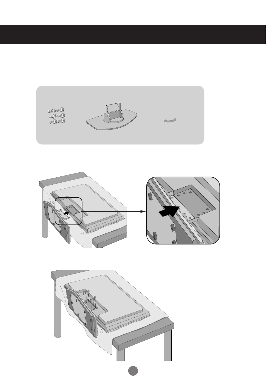
1. Take the parts for the stand out of the box and assemble them as shown in the
picture.
Parts
Screws (6)
First, check if the following parts are all present.
Stand (1)
cable management (1)
2. Place a soft cloth on the table and put the product with the screen facing
downward. Connect the stand as shown in the following picture.
3. Use the screws to secure the stand on the rear side of the product as shown in the
diagram.
1
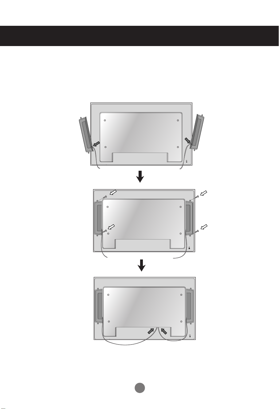
Connecting the Speakers
- Only on some models.
- Can be purchased separately if necessary.
Mount the product onto the speaker by using a screw as shown in the following
connect the speaker cable.
Type 1
When the speaker is installed.
*Connect the input terminal with a proper
color match.
2
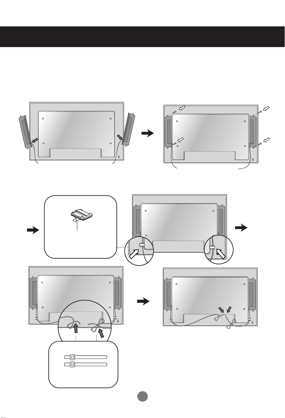
Connecting the Speakers
- Only on some models.
Mount the product onto the speaker by using a screw as shown in the following
connect the speaker cable.
Type 2
After installing your speakers, use holders and cable ties to organize the speaker cables.
Cable holder
Remove the paper.
* This feature is not available in all model.
Cable tie
* This feature is not available in all model.
When the speaker is installed.
*Connect the input terminal with a proper color
match.
3
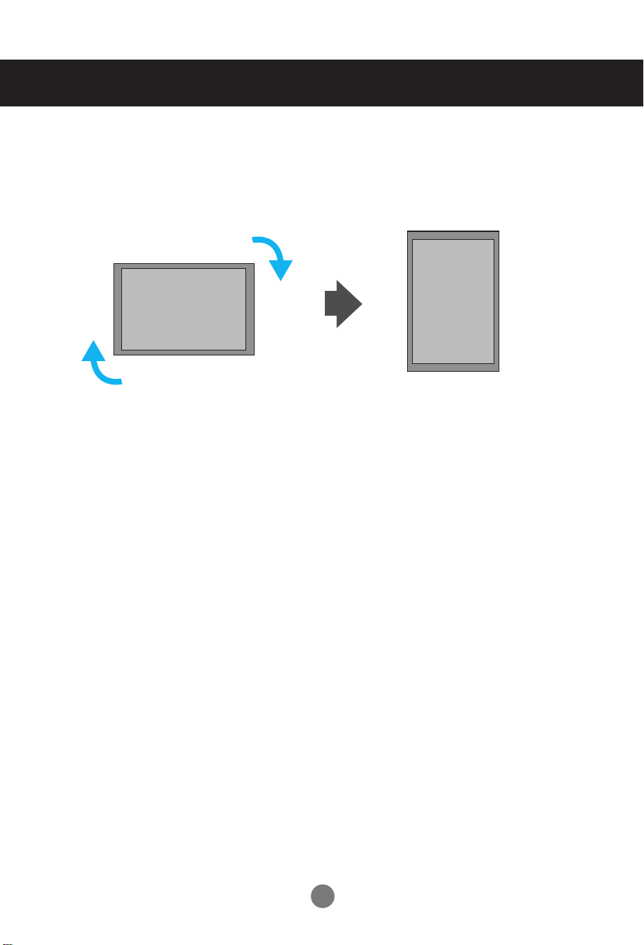
To install Portrait
"When installing Portrait, rotate it clockwise based on its front."
4
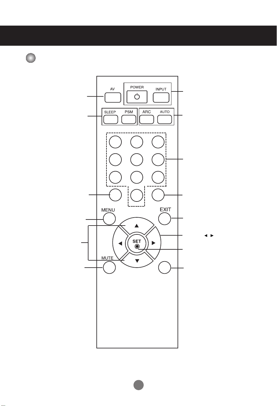
Using the Remote Control
Name of the Remote Control Buttons
•
AV Button
•
When watching AV, RGB PC,HDMI/DVI
,
Component1, Component2
The product will be automatically turned
off after a certain period of time.
Press this button repetitively to
select an appropriate time duration
- Toggles through preset video
Sleep Button
PSM Button
•
settings.
1 2 3
4 5 6
•
Power On/Off Button
•
Input Select Button
(See next page)
•
ARC button
Aspect Ratio Correction. Toggles
through aspect ratio options.
Auto Button
•
Automatic adjustment function
(Operational for the analog signal only)
There is not a function
which is supported
There is not a function
which is supported
•
Menu Button
•
UP and Down buttons
Bring up and down direction
adjustment.
Mute button
•
7 8
9
0
There is not a function
which is supported
•
Exit Button
•
Volume Button
Volume up and down
•
Check Button
*
There is not a function
which is supported
5
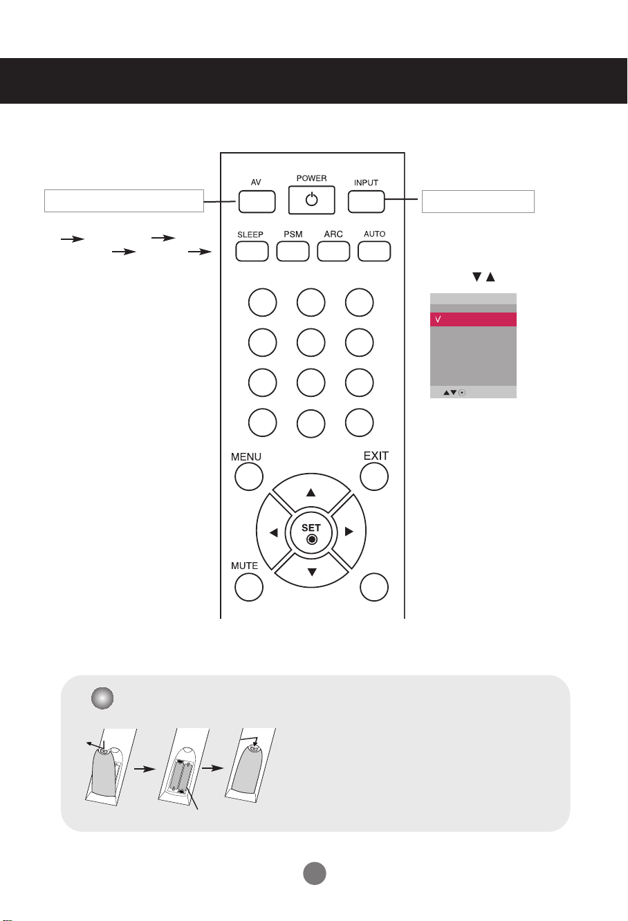
Using the Remote Control
1 2 3
4 5 6
7 8
0
9
*
•
AV Button
Toggles through video
AV Component1
Component2 RGB PC
HDMI/DVI
•
Input Select Button
If you press the button once,
the following Input Signal
Window will appear. Select
the signal type you want
using the button.
Input
AV
Component1
Component2
RGB PC
HDMI/DVI
Inserting batteries into remote control.
1. Slide off the battery cover.
2. Insert the batteries with correct polarity (+/-).
3. Close the battery cover.
• Dispose of used batteries in the recycle bin to prevent
environmental pollution.
AAA Type
6
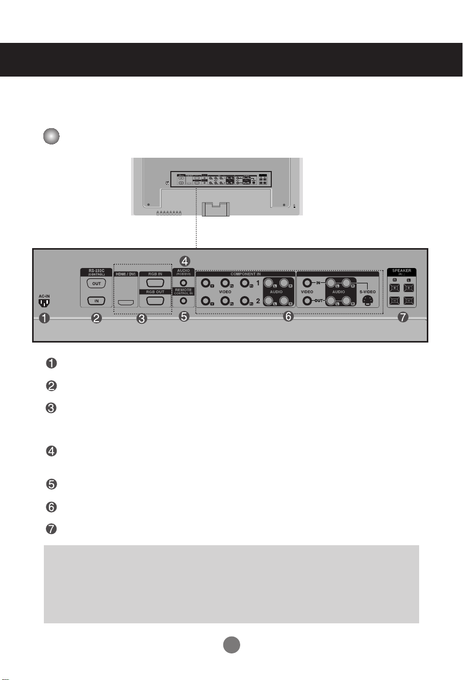
Name and Function of the Parts
AV IN/OUT
* The product image in the user’s guide could be different from the actual image.
Rear View
Power Connector : Connect the power cord
RS-232C Serial Ports
RGB PC, HDMI/DVI Ports
- HDMI Supports High Definition input and HDCP (High-bandwidth Digital Content
Protection). Some devices require HDCP in order to display HD signals.
PC Sound Jack
: Connect the audio cable to the *LINE OUT jack of the PC sound card.
Wired Remote Control Port
AV Ports
Speaker Ports
*LINE OUT
A terminal used to connect to the speaker including a built-in amplifier (Amp). Make sure that the
connecting terminal of the PC sound card is checked before connecting. If the Audio Out of PC sound
card has only Speaker Out, reduce the PC volume.
If the Audio Out of the PC sound card supports both Speaker Out and Line Out, convert to Line Out using
the card jumper of the program (Refer to the Sound Card Manual).
7
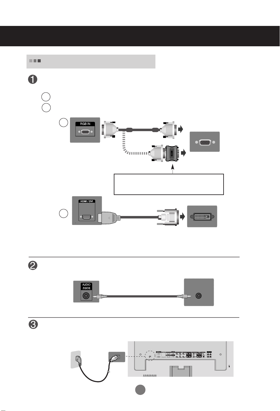
Connecting to External Devices
When Connecting to your PC
First of all, see if the computer, product and the peripherals are turned off.
Then, connect the signal input cable.
A
When connecting with the D-Sub signal input cable.
When connecting with the HDMI to DVI signal input cable (not included).
B
A
PC
Rear side of the product.
PC/
MAC
Macintosh Adapter (not included)
Use the standard Macintosh adapter since an incompatible
adapter is available in the market. (Different signaling system)
B
MAC
Rear side of the product.
* User must use shielded signal interface cables (D-sub 15 pin cable, DVI cable) with ferrite cores to maintain
standard compliance for the product.
(not included)
PC
Connect the Audio cable.
Rear side of the product.
PC
Connect the power cord.
Rear side of the product.
8
INPUT SET
SOURCE
AUTO/SET
Connecting to External Devices
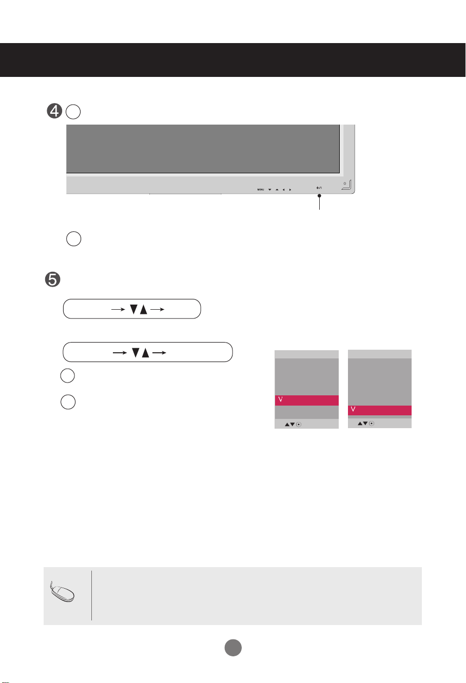
Turn on power by pressing the power button on the product.
1
Turn on the PC.
2
SOURCE
AUTO/SET
ON/OFF
Power button
Select an input signal.
Press the INPUT button on the remote control to select the input signal.
Or, press the SOURCE button on the back of the product.
Input
AV
Component1
Component2
RGB PC
HDMI/DVI
When connecting with a D-Sub signal input cable.
A
• Select RGB PC : 15-pin
When connecting with a HDMI to DVI signal input cable.
B
• Select HDMI/DVI :
D-Sub
HDMI to DVI
analog signal.
Digital signal.
Input
AV
Component1
Component2
RGB PC
HDMI/DVI
Note
• How to connect to two computers.
Connect the signal cables (
Press the INPUT button on the remote control to select the computer to use.
HDMI to DVI and D-Sub) to each computer.
• Directly connect to a grounded power outlet or power strip (three prong connector.)
9
RGB IN
RGB OUT
RGB IN
RGB OUT
RGB IN
RGB OUT
RGB IN
RGB OUT
Connecting to External Devices
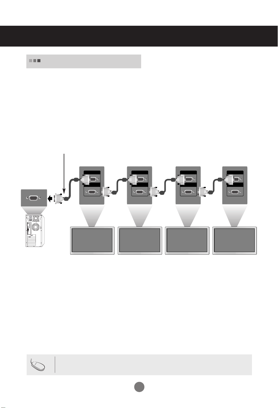
Daisy Chain Monitors
Use this function when displaying ANALOG RGB inputs of a PC to the other product.
•
To use different products connected to each other
Connect one end of the signal input cable(15-pin D-Sub Signal Cable) to the RGB OUT
connector of product 1 and connect the other end to the RGB IN connector of other
products.
15-pin D-Sub Signal Cable
PC
PC
Note
Product 1
Product 2
• When multi-connecting in/out cascade format, no loss cables are recommended.
Product 3
Product 4
We recommend that you should use cable distributor.
10
Connecting to External Devices
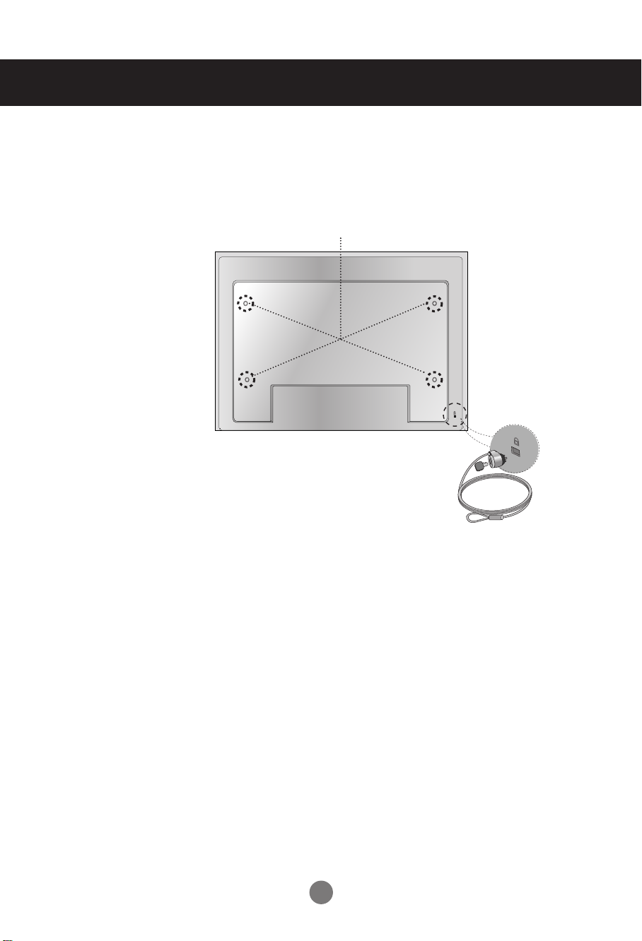
VESA FDMI wall Mounting
This product supports a VESA FDMI compliant mounting interface. These mounts are purchaed
separately and not available from LG. Refer to the instructions included with hte mount for more
info.
The Set is equipped with a kensington Securify
System connector on the back panel. The cable and lock
are available separate and are not sold by LG. For more
info, visit http://www.kensington.com, the internet home
page of the Kensington company.
11
Connecting to External Devices
IN
OUT
INPUT SET
SOURCE
AUTO/SET
IN
OUT
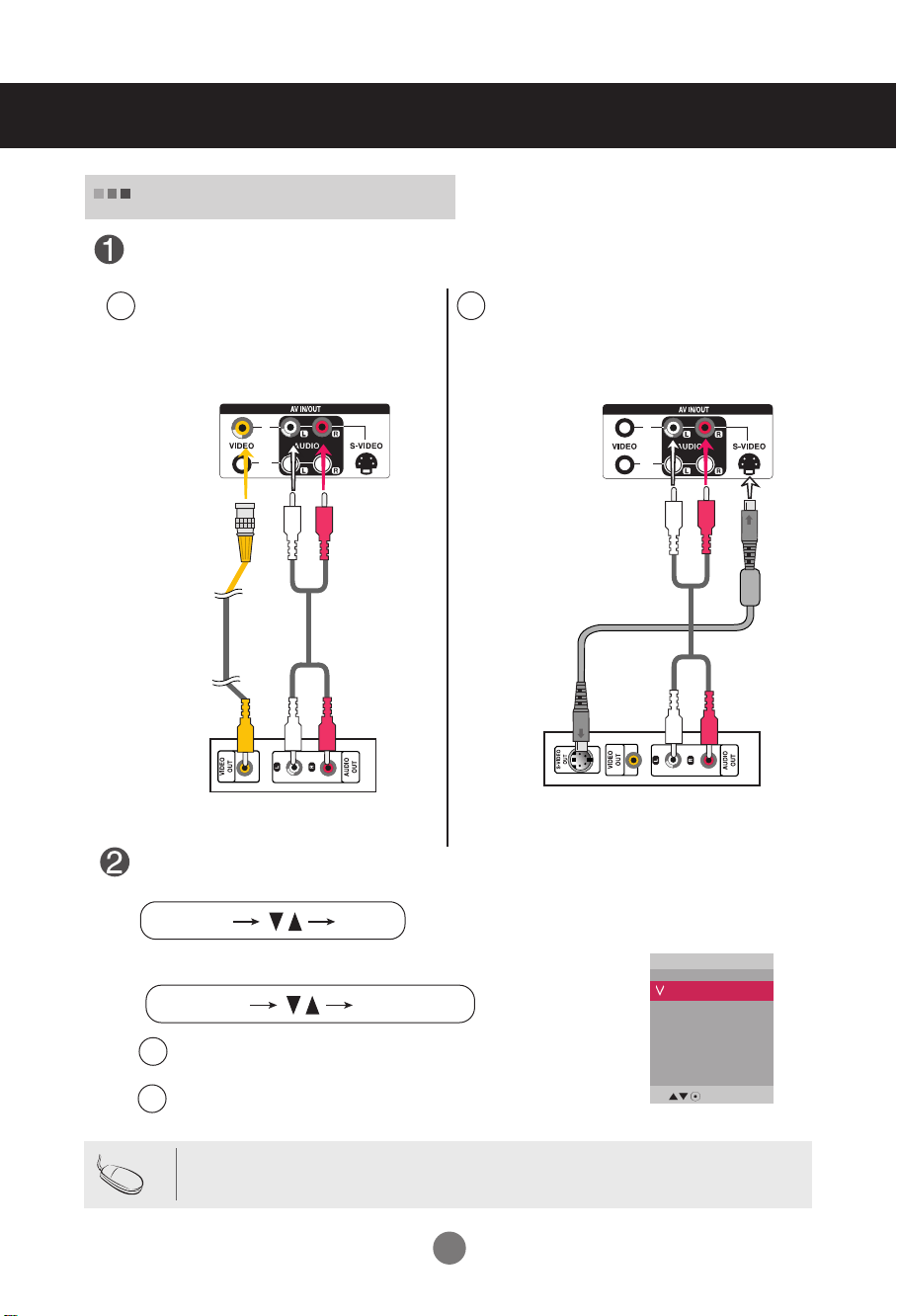
Video Input
Connect the video cable as shown in the below figure and then connect the power
cord (See page 8)
When connecting with a BNC cable.
A
•
Connect the input terminal with a
proper color match.
When connecting with a S-Video cable.
B
•
Connect to the S-Video input terminal to
watch high image quality movies.
Product
S-Video Cable
(not included)
BNC Cable
(not included)
Product
RCA Audio Cable
(not included)
VCR/DVD Receiver
RCA Audio Cable
(not included)
VCR/DVD Receiver
Select an input signal.
Press the INPUT button on the remote control to select the input signal.
Or, press the SOURCE button on the back of the product.
When connecting with an BNC cable.
A
Select AV.
•
When connecting with an S-Video cable.
B
•
Select AV.
Input
AV
Component1
Component2
RGB PC
HDMI/DVI
Note
• When the BNC cable is connected simultaneously with S-Video cable, S-Video input has a priority.
12
M
INPUT SET
SOURCE
AUTO/SET
M
Connecting to External Devices
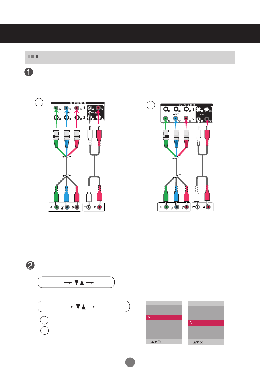
Component Input (480i/480p/576i/576p/720p/1080i/1080p)
Connect the video/audio cable as shown in the below figure and then, connect the
power cord (See page 8).
•
Connect the input terminal with a proper color match.
A
BNC Cable
(not included)
Product
RCA Audio Cable
(not included)
B
BNC Cable
(not included)
HDTV Receiver
Note
- Some devices may require HDCP in order to display HD signals.
- Component doesn't support HDCP.
Select an input signal.
Product
HDTV Receiver
RCA Audio Cable
(not included)
Press the INPUT button on the remote control to select the input signal.
Or, press the SOURCE button on the back of the product.
A
B
Select Component 1
•
Select Component 2
•
13
Input
AV
Component1
Component2
RGB PC
HDMI/DVI
Input
AV
Component1
Component2
RGB PC
HDMI/DVI
INPUT SET
SOURCE
AUTO/SET
Connecting to External Devices
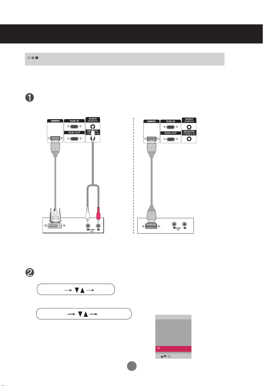
HDMI Input (480p/576p/720p/1080i/1080p)
- HDMI Supports High Definition input and HDCP (High-bandwidth Digital Content Protection).
Some devices require HDCP in order to display HD signals.
Connect the video/audio cable as shown in the below figure and then connect the
power cord (See page 8).
Product
Product
HDMI to DVI
Signal Cable
(not included)
VCR/DVD/Set-top Box
RCA-PC
Audio Cable
(not included)
HDMI Signal Cable
(not included)
VCR/DVD/Set-top Box
Note : Dolby Digital is not supported.
Select an input signal.
Press the INPUT button on the remote control to select the input signal.
Or, press the SOURCE button on the back of the product.
Input
When connecting with a HDMI to DVI signal input cable.
When connecting with a HDMI signal input cable.
• Select HDMI/DVI
AV
Component1
Component2
RGB PC
HDMI/DVI
14
IN
OUT
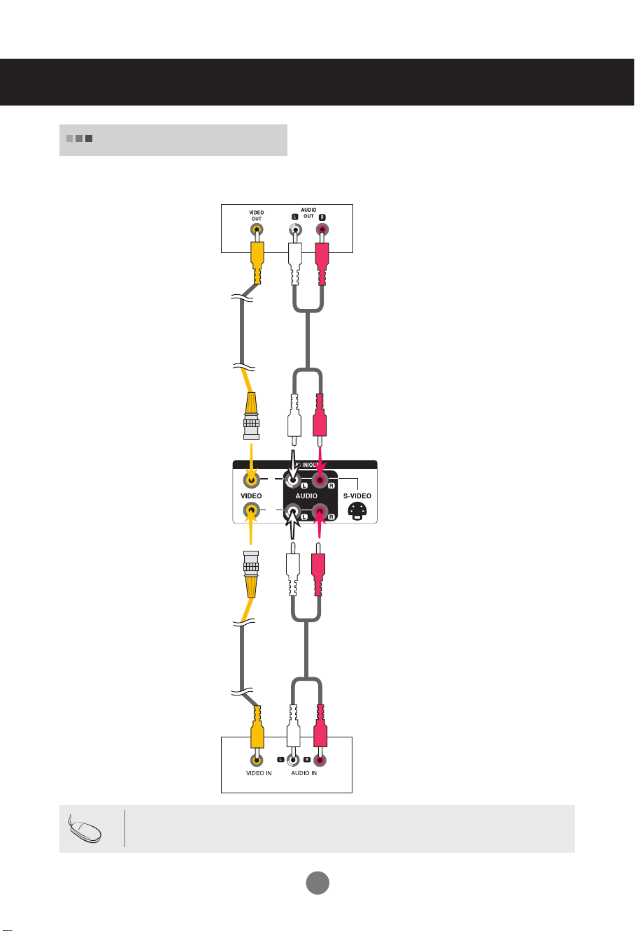
Connecting to External Devices
Watching
AV Outputs
- When using AV input, you can connect the AV Out to other monitors.
Video/TV
BNC Cable
(not included)
Audio Cable
(not included)
Product
Note
BNC Cable
(not included)
Audio Cable
(not included)
Video/TV
• When multi-connecting in/out cascade format, no loss cables are recommended.
We recommend that you should use cable distributor.
15

Cable management
- Only on some models.
Arrange the cables in the center as shown in the following picture.
1.
2.
Fit the cable guide to the back to help manage the cables.
cable
management
Removing the cable guide.
Hold the Cable management with both
hands and pull it downward.
Warning
• Do not use the cable management as a handle for the Monitor.
16
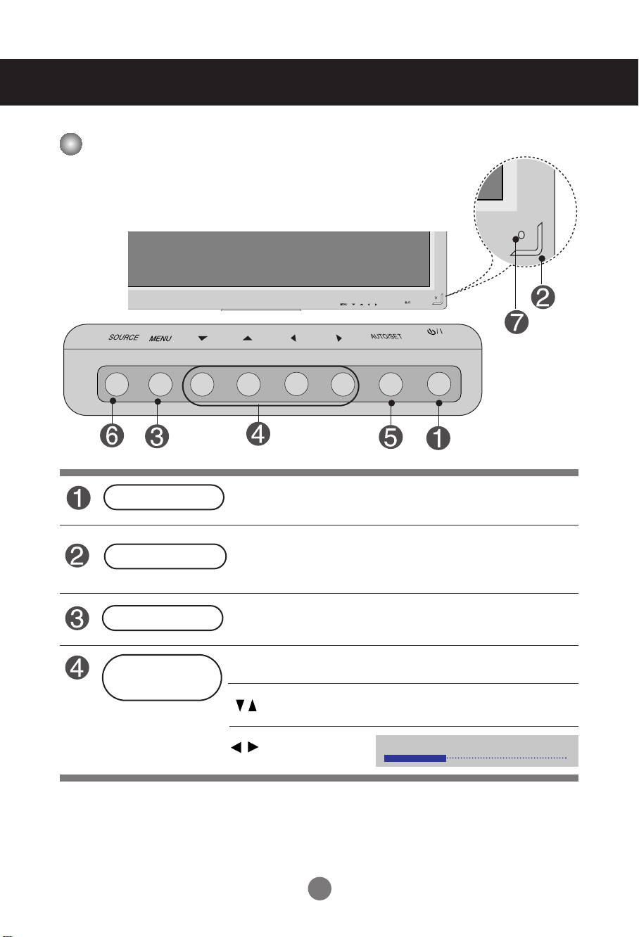
User Menus
ON/OFF
Screen Adjustment options
Power Button
Power Indicator
MENU Button
OSD Select /
Adjust Button
SOURCE
• Press this button to turn on the power. Press this button again to
turn it off.
• This Indicator lights up blue when the display operates normally(on
mode). If the display is in sleep (Energy Saving) mode, this indicator
color changes to amber.
• Use this button to show/hide the OSD (On Screen Display) menu
screen.
• Use
this
button to select an icon or adjust the setting in the OSD screen.
• Adjust the up and down.
AUTO/SET
ON/OFF
• Adjust the volume.
17
Volume
35
SOURCE
AUTO/SET
User Menus
Screen Adjustment options
AUTO/SET Button
SOURCE Button
IR Receiver
[For PC Analog signal]
[When XGA Mode is active and
1920 x 1080 is selected]
- Toggles between inputs
AV Composite Video, Separate Video
Component 1 HDTV, DVD
Component 2 HDTV, DVD
RGB PC 15-pin D-Sub analog signal
HDMI/DVI Digital signal
• This is where the unit receives signals from the remote control.
Input
AV
Component1
Component2
RGB PC
HDMI/DVI
18
User Menus
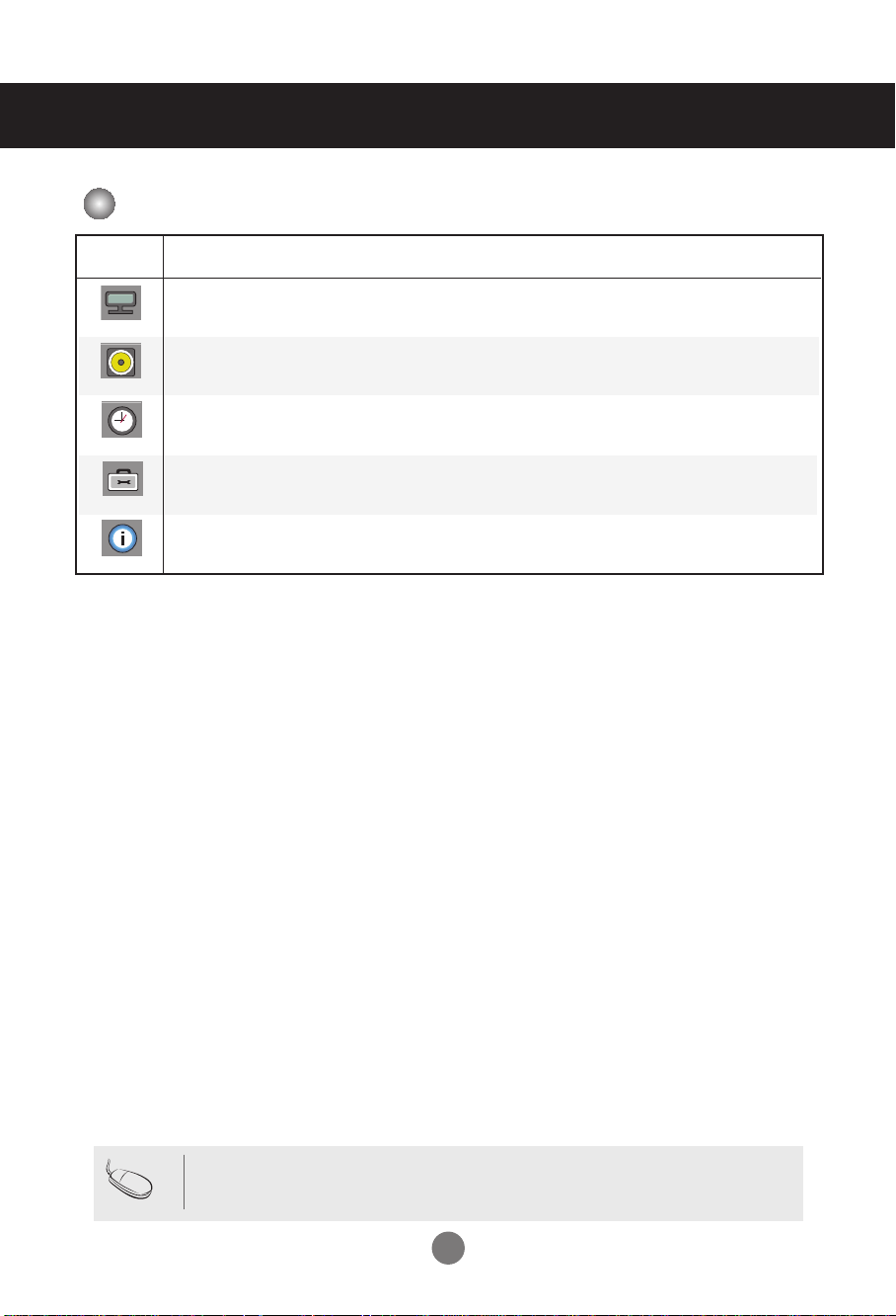
OSD Menu
Icon Function Description
Adjusts screen brightness, contrast and color that you prefer.
Picture
Audio
Time
Option
Information
Adjusts the audio options.
Adjusts the timer options.
Adjusts the screen status according to the circumstances.
Adjust Set ID and check Serial No. and SW version.
Note
OSD(On Screen Display)
The OSD function enables you to adjust the screen status conveniently since it provides
graphical presentation.
19
User Menus
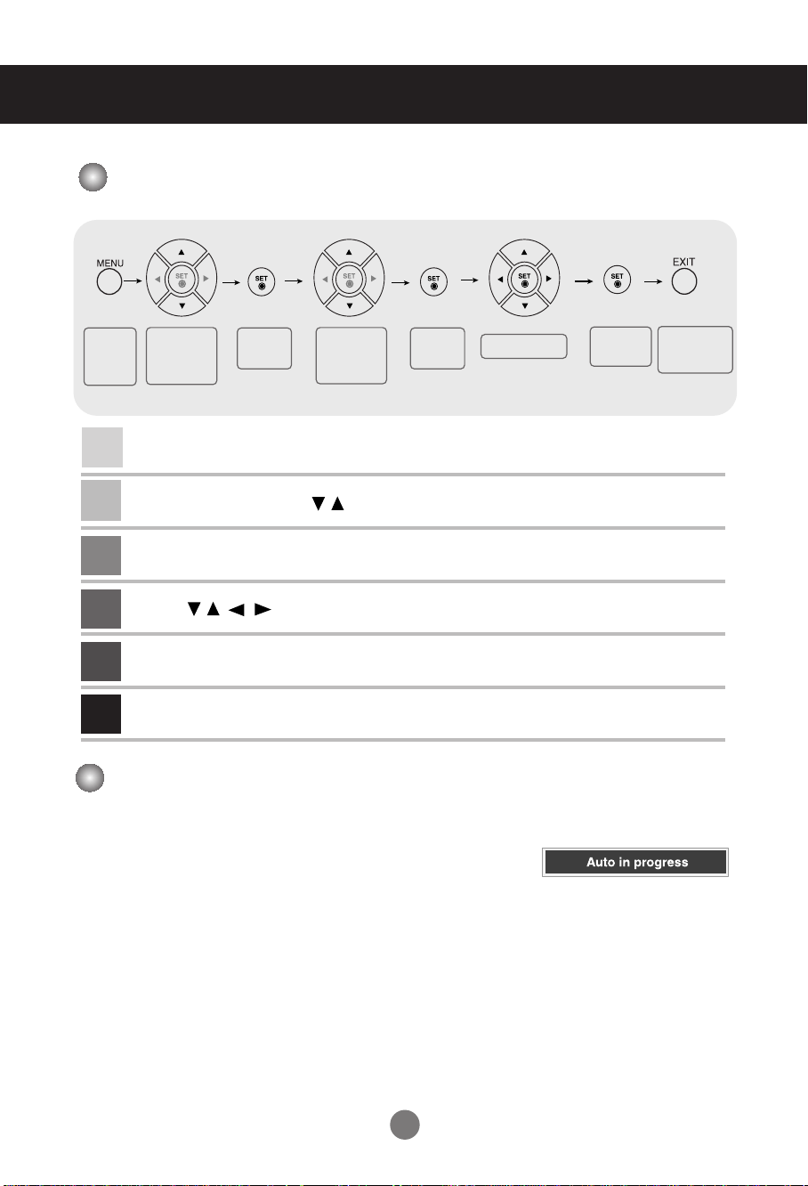
How to adjust the OSD (On Screen Display) screen
Pops up
the menu
screen
2
3
4
5
6
Move where
you want to
adjust
1
Press the MENU Button, then the main menu of the OSD appears.
To access a control, use the Buttons.
When the icon you want becomes highlighted, press the SET Button.
Use the Buttons to adjust the item to the desired level.
Accept the changes by pressing the SET Button.
Exit the OSD by pressing the EXIT Button.
Select a
menu icon
Move where
you want to
adjust
Select a
menu icon
•
Use the remote control to adjust the OSD screen.
Adjust the status
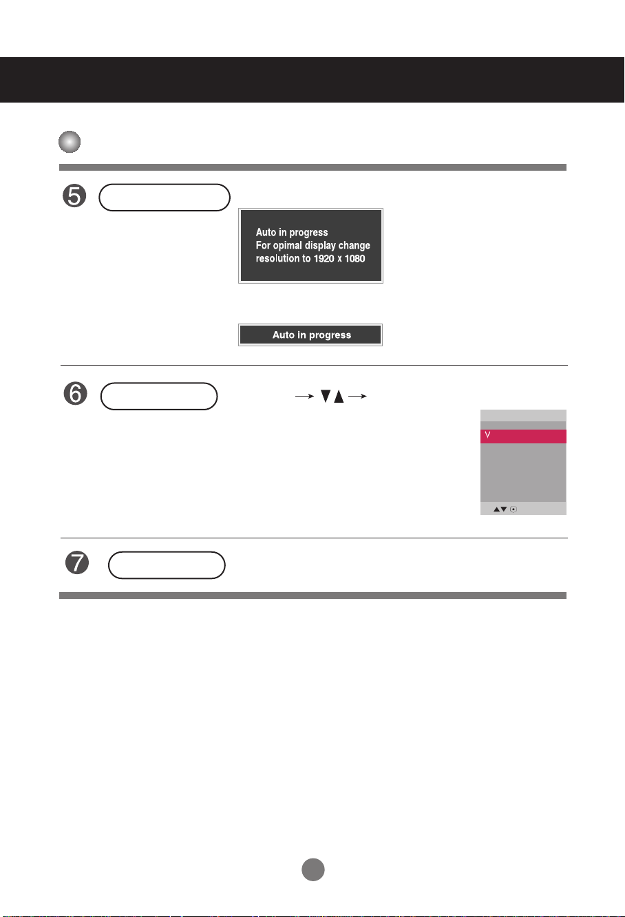
How to adjust the screen automatically
Press the AUTO/SET button (AUTO button on a remote Control) in
the PC analog signal. Then optimal screen settings will be selected
that fit into the current mode. If adjustment is not satisfactory, you can
adjust the screen manually.
Save
adjustment
[When XGA Mode is active and
1920 x 1080 is selected]
Exit from the
menu screen.
20
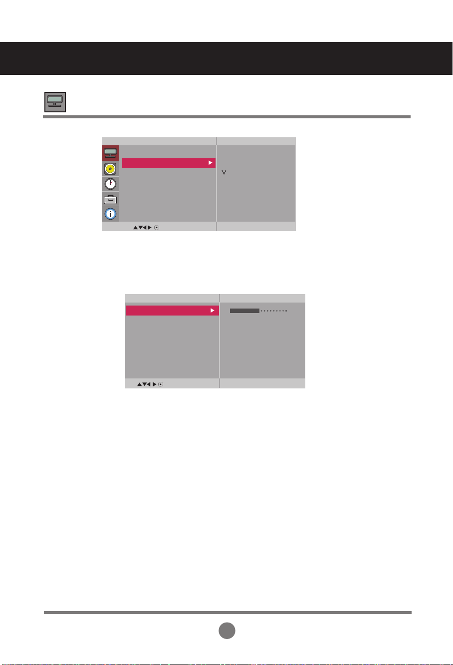
User Menus
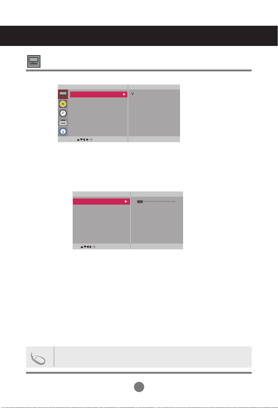
Adjusting Screen Color
Picture
Mode
Picture
Picture Mode
Color Temperature
Advanced
Aspect Ratio
Picture Reset
Screen
MENU
Vivid
Standard
Cinema
Sport
Game
User1
User2
Toggles between screen presets.
• Vivid : Select this option to display with a sharp image.
• Standard : The most general and natural screen display status.
• Cinema : Select this option to lower brightness by one level.
• Sport : Select this option to display with a soft image.
• Game : To enjoy dynamic image when playing a game.
• User1,2 : Select this option to use the user-defined settings.
User2
Backlight 20
Contrast 90
Brightness 50
Color 50
Sharpness 50
Tint 50
Expert
MENU
Backlight : To control the brightness of the screen,adjust the brightness of LCD panel.
Contrast : Adjust the difference between the light and dark levels in the picture.
Brightness : To adjust the brightness of the screen.
Color : To adjust the color to desired level.
Sharpness : To adjust the clearness of the screen.
Tint :To adjust the tint to desired level.
Expert : To compensate for each image mode, or adjust image values according to a
particular image. (Applied only to User2 menu.)
Note
If the '
Picture Mode
' setting in the Picturemenu is set to Vivid, Standard, Cinema,
Sport or Game the subsequent menus will be automatically set.
21
User Menus
Adjusting Screen Color
Color
Temperature
Picture
Picture Mode
Color Temperature
Advanced
Aspect Ratio
Picture Reset
Screen
MENU
Color Settings
• Cool : Slightly purplish white.
• Medium : Slightly bluish white.
• Warm : Slightly reddish white.
• User : Select this option to use the user-defined settings.
User
Red 0
Green 0
Blue 0
MENU
Red / Green / Blue
Set your own color levels.
Cool
Medium
Warm
User
22
 Loading...