

LG LS-M3021AL, LS-M3060AL, LS-M3060HL, LS-M3060CL, LS-M3060BL Service Manual
...
Room Air Conditioner
SERVICE MANUAL
CAUTION
-BEFORE SERVICING THE UNIT, READ THE SAFETY
PRECAUTIONS IN THIS MANUAL.
-ONLY FOR AUTHORIZED SERVICE PERSONNEL.
MODELS : LS-M3021CL/AL
LS-M3060HL/CL/AL/BL
LS-M3061HL/CL/BL/AL
LS-M3063CL
LS-M3064HL/CL/DL/EL/DM/EM
LS-M3221HL/CL/BL/AL
LS-N3621CL/AL
LS-N3660HL/CL/AL/BL
LS-N3661HL/CL/AL/BL
LS-N3664EL
LS-N3821HL/CL/BL/AL
LS-M306LCL/LDL
LS-M306LHL/LEL
LS-C366NLD0
LS-H366NLD0/NMD0
LS-N3621BL/HL
LS-C366NLA0
LS-C366NLB0
WEBSITE http://biz.LGservice.com
E-MAIL http://www.LGEservice.com/techsup.html

-2-
Contents
Functions
.................................................................................................................................3
Product Specifications
..........................................................................................................5
Dimensions
..............................................................................................................................8
Refrigeration Cycle Diagram
................................................................................................11
Pipe Length and the Elevation.............................................................................................12
Wiring Diagram
......................................................................................................................13
Operation Details
..................................................................................................................15
Display Function
...................................................................................................................22
Self-diagnosis Function
........................................................................................................22
Installation
.............................................................................................................................23
Operation
...............................................................................................................................39
Disassembly of the parts (Indoor Unit)
...............................................................................41
3-way Valve
............................................................................................................................49
Cycle Troubleshooting Guide
...............................................................................................54
Electronic Parts Troubleshooting Guide
.............................................................................55
Electronic Control Device
.....................................................................................................61
Schematic Diagram
...............................................................................................................64
Exploded View and Replacement Parts List
.......................................................................72
-3-
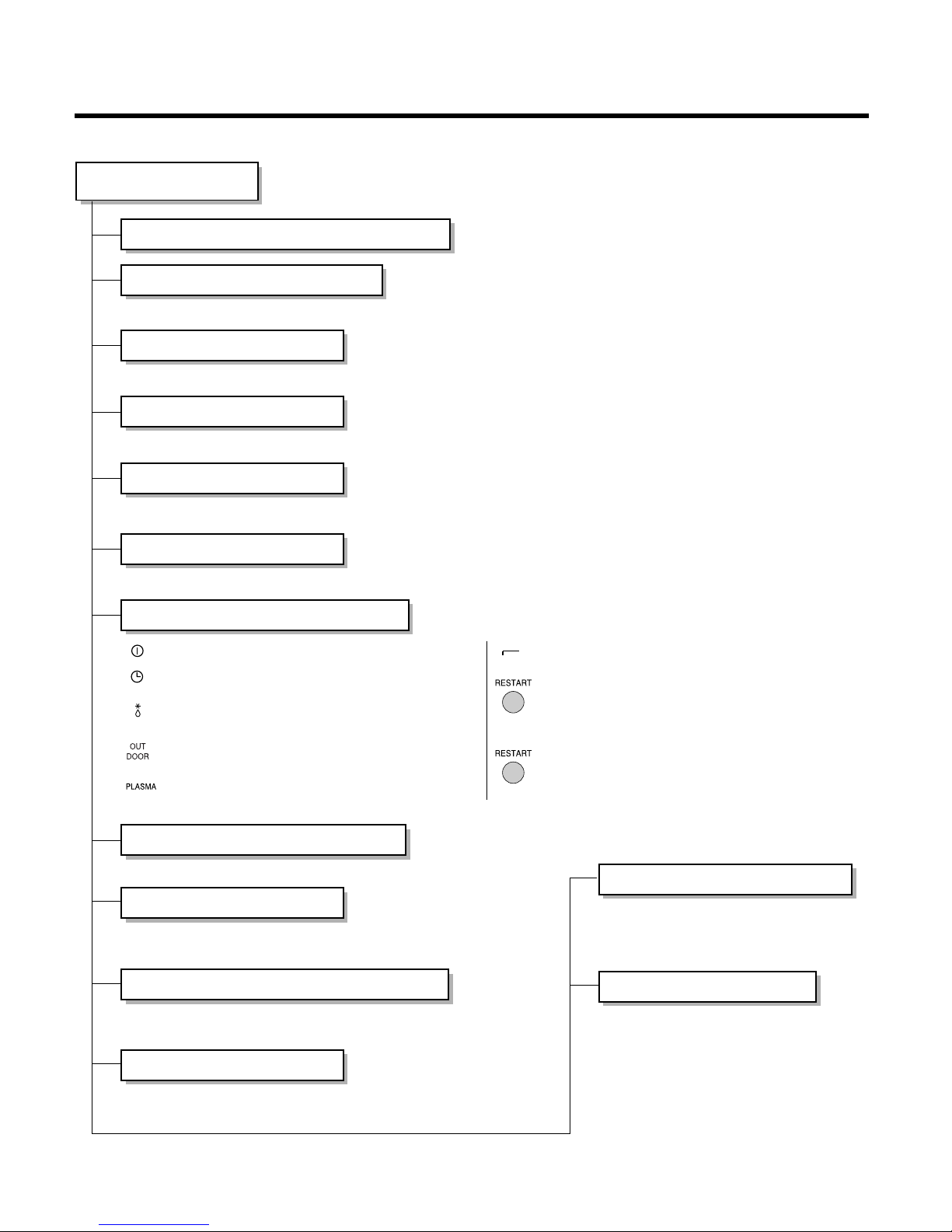
Functions
• Room temperature sensor. (THERMISTOR)
• Maintains the room temperature in accordance with the Setting Temp.
• Indoor fan is delayed for 5 sec at the starting.
• Restarting is inhibited for approx. 3 minutes.
• High, Med, Low
• Intermittent operation of fan at low speed.
• The fan is switched to low(Cooling), med(Heating) speed.
• The unit will be stopped after 1, 2, 3, 4, 5, 6, 7 hours.
• The fan is switched to intermittent or irregular operation
•
The fan speed is automatically switched from high to low speed.
• The louver can be set at the desired position or swing
up and down automatically.
Indoor Unit
Operation ON/OFF by Remote controller
Sensing the Room Temperature
Room temperature control
Starting Current Control
Time Delay Safety Control
Indoor Fan Speed Control
Operation indication Lamps (LED)
Soft Dry Operation Mode
• Both the indoor and outdoor fan
stops during deicing.
• The indoor fan stops until the
evaporator piping temperature will be
reached at 28°C.
Sleep Mode Auto Control
Natural Air Control by CHAOS Logic
Airflow Direction Control
Deice (defrost) control (Heating)
Hot-start Control (Heating)
On/Off : Lights up during the system operation.
: Lights up during Timer operation or
Sleep mode.
Defrost Mode : Lights up during Defrost Mode or Hot
Start operation. (Heat pump model only)
: Lights up during outdoor unit operation.
(Cooling model only)
Plasma Mode : Lights up during plasma-purification
operation.(option)
Auto Restart Mode : Lights up during if Restart Button
is pressed.
Auto Restart Button : In failure of electric power, if the
button is pressed the unit runs as
previous setting operation when
power returns.
Forced Operation Button
: Operation starts, when this button
is pressed and stops when you
press the button again.
Outdoor unit
operation
Timer or
Sleep Mode
-4-
Healthy Dehumidification Operation Mode.
( )
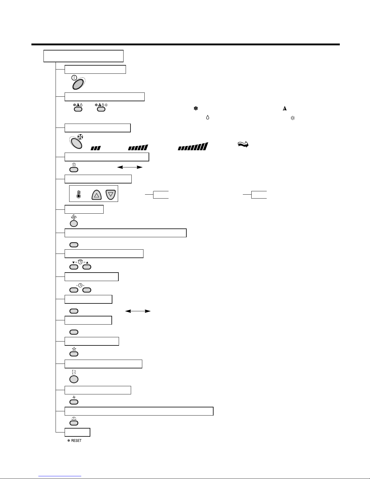
Remote Controller
Operation ON/OFF
Reset
Operation Mode Selection
Temperature Setting
Timer Selection
Timer Setting
JET COOL
Timer Cancel
Sleep Operation
Airflow Direction Control
(Cooling
model only)
(Heating
model only)
TEMPERATURE
LOW HIGH
Cooling Operation Mode.( )
Heating Operation Mode.( )
Auto Operation Mode.( )
Fan Operation Mode
Horizontal Airflow Direction Control Button(Option)
Room, Temperature Display
Setting the Time or Timer
PLASMA(Option)/NEGATIVE ION(Option)
ON OFF
SET
PLASMA
CANCEL
Fan Speed Selection
(Low) (Med) (High) (CHAOS)
: (High:39°C Low:11°C)
: OFF, ON, OFF ON
: Cancel Sleep Mode, Timer ON or Timer OFF
: 1, 2, 3, 4, 5, 6, 7, Off Timer
: Fan Operates without cooling or heating.
Cooling
Down to 18°C
Up to 30°C
Heating
Down to 16°C
Up to 30°C
-5-
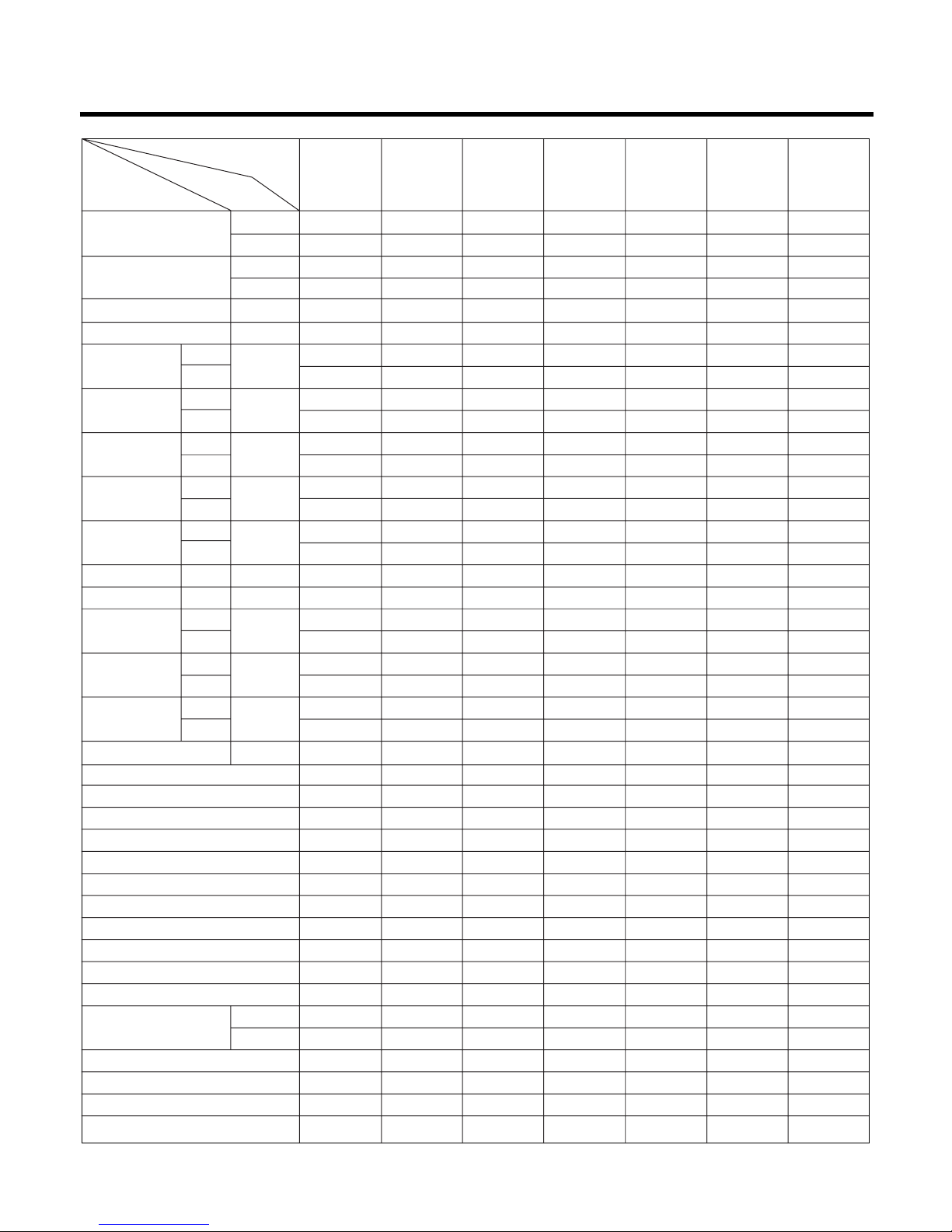
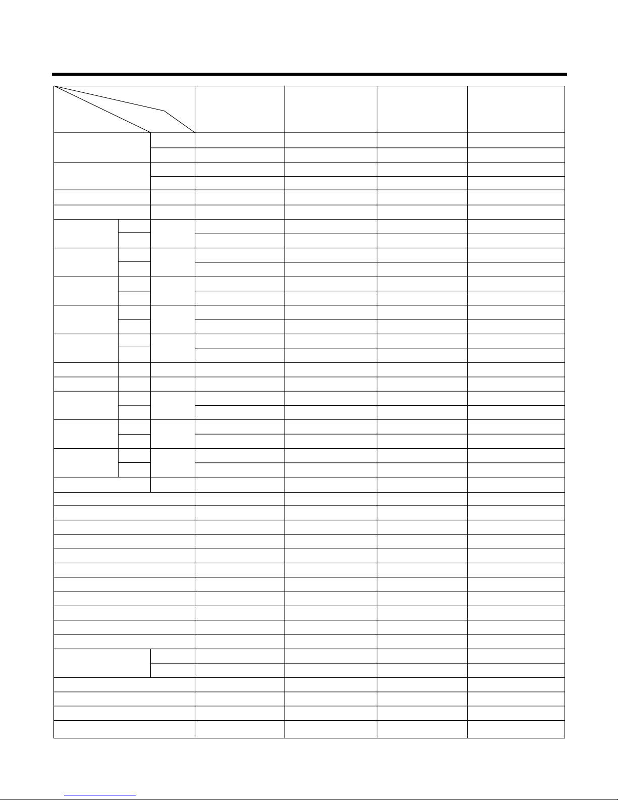
Product Specifications (30K, 32K)
Cooling Capacity
BTU/h(kcal/h)
W
Heating Capacity
BTU/h(kcal/h)
W
Moisture Removal l/h
Power Source Ø,V,Hz
Air Circulation m3/min
Noise Level dB(A)±3
Input W
Runnig Current A
Starting Current A
E.E.R. BTU/h-W
C.O.P W/W
Motor Output W
mm
Net. Weight kg
Refrigerant(R-22) g
Airflow Direction Control (Up & Down)
Airflow Direction Control (Right & Left)
Negative lon
Air Purifying Filter
Deicer
Hot Start
Chaos Wind
Micom Dry
Timer
Self Diagnosis
Remocon type
Service valve
Sleeping Operation
Drain Hose
Connecting Cable
Power Cord
28,000(7,056) 28,000(7,056) 28,000(7,056) 28,000 28,000(7,056)
8,205 8,205/9,377 8,205 8,205 8,205/9,377 8,205 8,205
29,000(7,308) 29,000(7,308) - - - -
8,498/9,377 8,498/9,377 8,498 - - - -
3.8 3.8 3.8 3.8 3.8 3.8 3.8
1ø,220-240V, 50Hz 1ø,220-240V, 50Hz 1ø,220-240V, 50Hz 1ø,220-240V, 50Hz 1ø,220-240V, 50Hz
21 21 21 21 21 21 21
58 58 58 58 58 58 58
46 46 46 46 46 46 46
58 58 58 58 58 58 58
3,200 3,200/3,350 3,200 3,200 3,200/3,350 3,200 3,200
3,100 3,100/3,350 3,100 - - - -
15.5 15.5/16.0 15.5 15.5 15.5/16.0 15.5 15.5
15 15/16.0 15 - - - -
85 85 43 85 85 85 85
85 85 43 - - - -
8.75 8.75/9.55 8.75 8.75 8.75/9.55 8.75 8.75
2.74 2.74/2.80 2.74 - - - -
47 47 47 47 47 47 47
80 80 80 80 80 80 80
1,259 x 349 x 205 1,259 x 349 x 205 1,259 x 349 x 205 1,259 x 349 x 205 1,259 x 349 x 205 1,259 x 349 x 205 1,259 x 349 x 205
870 x 800 x 320 870 x 800 x 320 870 x 800 x 320 870 x 800 x 320 870 x 800 x 320 870 x 800 x 320 870 x 800 x 320
20 20 20 20 20 20 20
72 72 72 71 71 71 71
2,100 2,100 2,100/2,550 1,950 1,950/2,420 2,550 1,950
YES YES YES YES YES YES YES
NO NO/YES NO(YES) NO NO/YES NO(YES) NO(YES)
NO NO NO NO NO NO NO
NO(OPTION) YES YES NO(OPTION) YES YES YES
YES YES YES NO NO NO NO
YES YES YES NO NO NO NO
YES YES YES YES YES YES YES
YES YES YES YES YES YES YES
24hr ON/OFF 24hr ON/OFF 24hr ON/OFF 24hr ON/OFF 24hr ON/OFF 24hr ON/OFF 24hr ON/OFF
YES YES YES YES YES YES YES
L.C.D Wireless L.C.D Wireless L.C.D Wireless L.C.D Wireless L.C.D Wireless L.C.D Wireless L.C.D Wireless
3/8"(9.52) 3/8"(9.52) 3/8"(9.52) 3/8"(9.52) 3/8"(9.52) 3/8"(9.52) 3/8"(9.52)
5/8"(15.88) 5/8"(15.88) 5/8"(15.88) 5/8"(15.88) 5/8"(15.88) 5/8"(15.88) 5/8"(15.88)
YES YES YES YES YES YES YES
YES YES YES YES YES YES YES
0.75mm
2
0.75mm
2
0.75mm
2
0.75mm20.75mm20.75mm
2
0.75mm
2
2.5mm
2
2.5mm
2
2.5mm
2
2.5mm
2
2.5mm
2
2.5mm
2
2.5mm
2
Model Name
Unit
Indoor
Outdoor
Indoor
Outdoor
Cooling
Heating
Cooling
Heating
Cooling
Heating
Cooling
Heating
Indoor
Outdoor
Indoor
Outdoor
Indoor
Outdoor
Liquid
Gas
Dimensions
(WxHxD)
Item
LS-M3061HL/BL
LS-M3221HL/BL
LS-M306LHL
LS-M306LEL
LS-M3060HL
LS-M3060BL
LS-M3064HL
(LS-M3064EL)
LS-M3064EM
LS-M306LCL
LS-M306LDL
LS-M3060CL
LS-M3060AL
LS-M3061CL/AL
LS-M3221CL/AL
LS-M3021CL/AL
LS-M3064CL
(LS-M3064DL)
LS-M3064DM
LS-M3063CL
28,000(7,056)/
32,000(8,064)
29,000(7,308)/
32,000(8,064)
1ø,220-240V, 50Hz/
1ø,220V, 60Hz
1ø,220-240V, 50Hz/
1ø,220V, 60Hz
28,000(7,056)/
32,000(8,064)
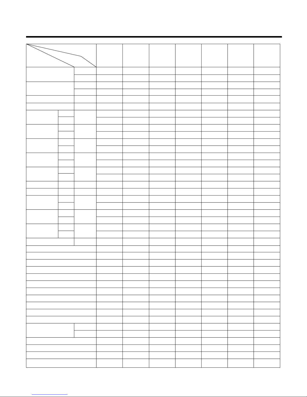
-6-
Cooling Capacity
BTU/h(kcal/h)
W
Heating Capacity
BTU/h(kcal/h)
W
Moisture Removal l/h
Power Source Ø,V,Hz
Air Circulation m3/min
Noise Level dB(A)±3
Input W
Runnig Current A
Starting Current A
E.E.R. BTU/h-W
C.O.P W/W
Motor Output W
mm
Net. Weight kg
Refrigerant(R-22) g
Airflow Direction Control (Up & Down)
Airflow Direction Control (Right & Left)
Negative lon
Air Purifying Filter
Deicer
Hot Start
Chaos Wind
Micom Dry
Timer
Self Diagnosis
Remocon type
Service valve
Sleeping Operation
Drain Hose
Connecting Cable
Power Cord
36,000(9,073) 36,000(9,073) 36,000(9,073) 36,000(9,073) 38,000(9,557) 38,000(9,577) 36,000(9,073)
10,549 10,549 10,549 10,549 11,135 11,135 10,549
36,000(9,073) 36,000(9,073) - - 3,800(9,577) - -
10,549 10,549 - - 11,135 - -
4.2 4.2 4.2 4.2 4.2 4.2 4.2
1ø,220-240V, 50Hz 1ø,220-240V, 50Hz 1ø,220-240V, 50Hz 1ø,220-240V, 50Hz 1ø,220-240V, 60Hz 1ø,220-240V, 60Hz 1ø,220-240V, 60Hz
26 26 26 26 26 26 26
58 58 58 58 58 58 58
47 47 47 47 47 47 47
58 58 58 58 58 58 58
4,300 4,300 4,300 4,300 3,970 3,970 3,970
4,300 4,300 - - 3,970 - -
22 22 22 22 19 19 19
22 22 - - 19 - -
113 113 113 113 91 91 91
113 113 - - 91 - -
8.37 8.37 8.37 8.37 9.23 9.23 9.23
2.45 2.45 - - 2.45 - -
65 65 65 65 38 38 38
50 50 50 50 30 30 30
1,499 x 349 x 205 1,499 x 349 x 205 1,499 x 349 x 205 1,499 x 349 x 205 1,499 x 349 x 205 1,499 x 349 x 205 1,499 x 349 x 205
790 x 965 x 320 790 x 965 x 320 790 x 965 x 320 790 x 965 x 320 790 x 965 x 320 790 x 965 x 320 790 x 965 x 320
25 25 25 25 25 25 25
80 80 80 80 80 80 80
2,100 2,100 2,100 1,950 1,950 1,950 1,950
YES YES YES YES YES YES YES
NO YES NO YES YES YES YES
NO NO NO NO NO NO NO
NO(OPTIONAL) YES NO(OPTIONAL) YES YES YES YES
YES YES NO NO YES NO NO
YES YES NO NO YES NO NO
YES YES YES YES YES YES YES
YES YES YES YES YES YES YES
24hr ON/OFF 24hr ON/OFF 24hr ON/OFF 24hr ON/OFF 24hr ON/OFF 24hr ON/OFF 24hr ON/OFF
YES YES YES YES YES YES YES
L.C.D Wireless L.C.D Wireless L.C.D Wireless L.C.D Wireless L.C.D Wireless L.C.D Wireless L.C.D Wireless
3/8"(9.52) 3/8"(9.52) 3/8"(9.52) 3/8"(9.52) 3/8"(9.52) 3/8"(9.52) 3/8"(9.52)
3/4"(19.05) 3/4"(19.05) 3/4"(19.05) 3/4"(19.05) 3/4"(19.05) 3/4"(19.05) 3/4"(19.05)
YES YES YES YES YES YES YES
YES YES YES YES YES YES YES
0.75mm
2
0.75mm20.75mm
2
0.75mm20.75mm
2
0.75mm20.75mm
2
5.5mm
2
5.5mm
2
5.5mm
2
5.5mm
2
5.5mm
2
5.5mm
2
5.5mm
2
Model Name
Unit
Indoor
Outdoor
Indoor
Outdoor
Cooling
Heating
Cooling
Heating
Cooling
Heating
Cooling
Heating
Indoor
Outdoor
Indoor
Outdoor
Indoor
Outdoor
Liquid
Gas
Dimensions
(WxHxD)
Item
LS-N3661HL/BL
LS-N3664EL
LS-N3660HL
LS-N3660BL
LS-N3660CL
LS-N3660AL
LS-N3661CL
LS-N3661AL
LS-N3821HL
LS-N3821BL
LS-N3821CL
LS-N3821AL
LS-N3621CL/AL
Product Specifications (36K, 38K)
-7-
Product Specifications (36K)
Cooling Capacity
BTU/h(kcal/h)
W
Heating Capacity
BTU/h(kcal/h)
W
Moisture Removal l/h
Power Source Ø,V,Hz
Air Circulation m3/min
Noise Level dB(A)
±3
Input W
Runnig Current A
Starting Current A
E.E.R. BTU/h-W
C.O.P W/W
Motor Output W
mm
Net. Weight kg
Refrigerant(R-22) g
Airflow Direction Control (Up & Down)
Airflow Direction Control (Right & Left)
Negative lon
Air Purifying Filter
Deicer
Hot Start
Chaos Wind
Micom Dry
Timer
Self Diagnosis
Remocon type
Service valve
Sleeping Operation
Drain Hose
Connecting Cable
Power Cord
36,000(9,073) 36,000(9,073) 36,000(9,073) 35,000(8,817)
10549 10549 10549 10254
36,000(9,073) - 36,000(9,073) 35,000(8,817)
10549 - 10549 10254
4.2 4.2 4.2 4.2
1ø, 220-240V, 50Hz 1ø, 220-240V, 50Hz 1ø, 220-240V, 50Hz 1ø, 220-240V, 50Hz
26 26 26 26
58 58 58 58
47 47 47 47
58 58 58 58
3970 4200 4200 4200
3970 - 3900 3900
19.0 19.0 19.0 19.0
19.0 - 18.0 18.0
91 91 113 113
91 - 113 113
9.23 9.23 8.37 8.33
2.41 - 2.45 2.63
65 65 65 65
50 50 50 50
1,499 x 349 x 205 1,499 x 349 x 205 1,499 x 349 x 205 1,499 x 349 x 205
790 x 965 x 320 790 x 965 x 320 790 x 965 x 320 790 x 965 x 320
25 25 25 25
80 80 80 80
3250 3240 3220 3220
YES YES YES YES
NO NO YES YES
NO NO NO NO
NO(OPTIONAL) NO(OPTIONAL) YES YES
NO NO YES YES
NO NO YES YES
YES YES YES YES
YES YES YES YES
24hr ON/OFF 24hr ON/OFF 24hr ON/OFF 24hr ON/OFF
YES YES YES YES
L.C.D Wireless L.C.D Wireless L.C.D Wireless L.C.D Wireless
3/8(9.52) 3/8(9.52) 3/8(9.52) 3/8(9.52)
3/4(19.05) 3/4(19.05) 3/4(19.05) 3/4(19.05)
YES YES YES YES
YES YES YES YES
0.75mm
2
0.75mm
2
0.75mm
2
0.75mm
2
5.5mm
2
5.5mm
2
5.5mm
2
5.5mm
2
Model Name
Unit
Indoor
Outdoor
Indoor
Outdoor
Cooling
Heating
Cooling
Heating
Cooling
Heating
Cooling
Heating
Indoor
Outdoor
Indoor
Outdoor
Indoor
Outdoor
Liquid
Gas
Dimensions
(WxHxD)
Item
LS-N3621BL
LS-N3621HL
LS-C366NLD0
LS-C366NLA0
LS-C366NLB0
LS-H366NLD0 LS-H366NMD0
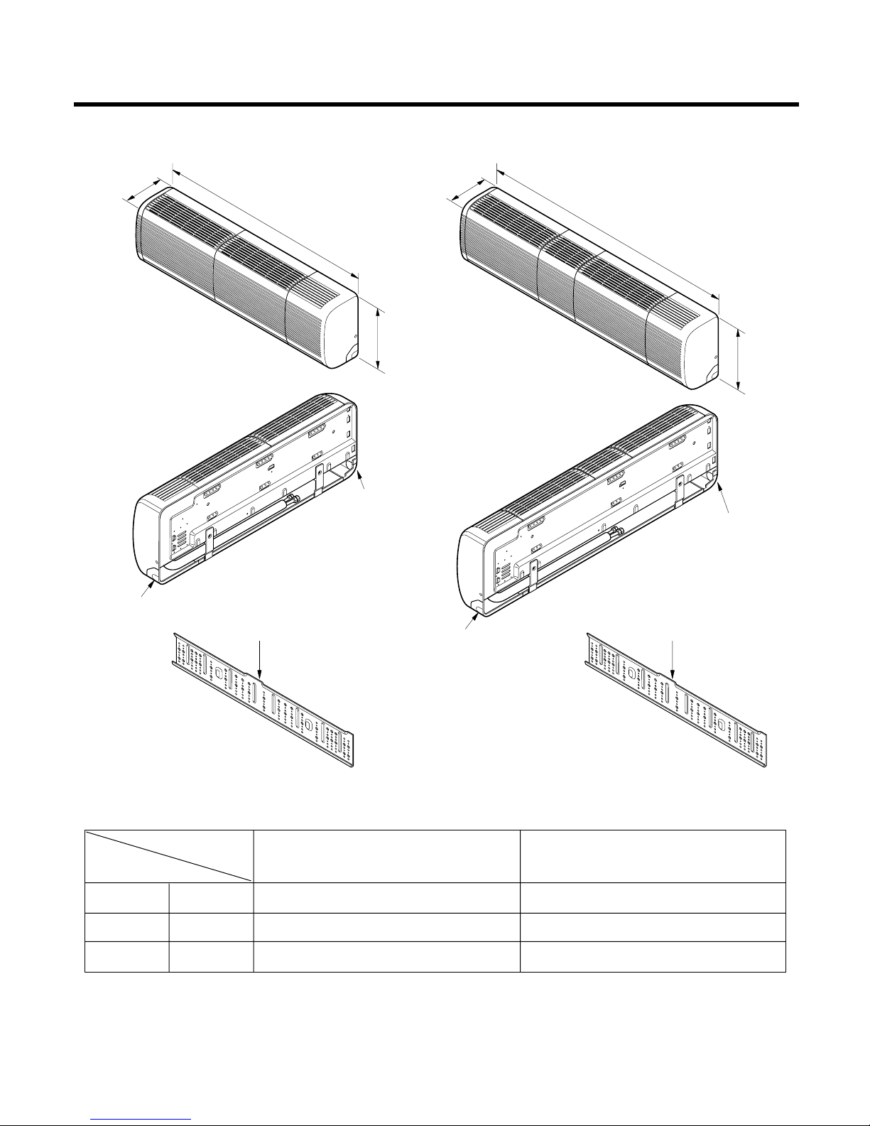
(1) Indoor Unit
-8-
Dimensions
Tubing hole cover
Tubing hole cover
Installation plate
D
W
H
W
H
Tubing hole cover
Tubing hole cover
Installation plate
D
W
H
Tubing hole cover
Tubing hole cover
Installation plate
D
W mm 1,259 1,499
H mm 349 349
D mm 205 205
Model
Dimension
SM CHASSIS SN CHASSIS
-9-
MODEL
DIM
-9-
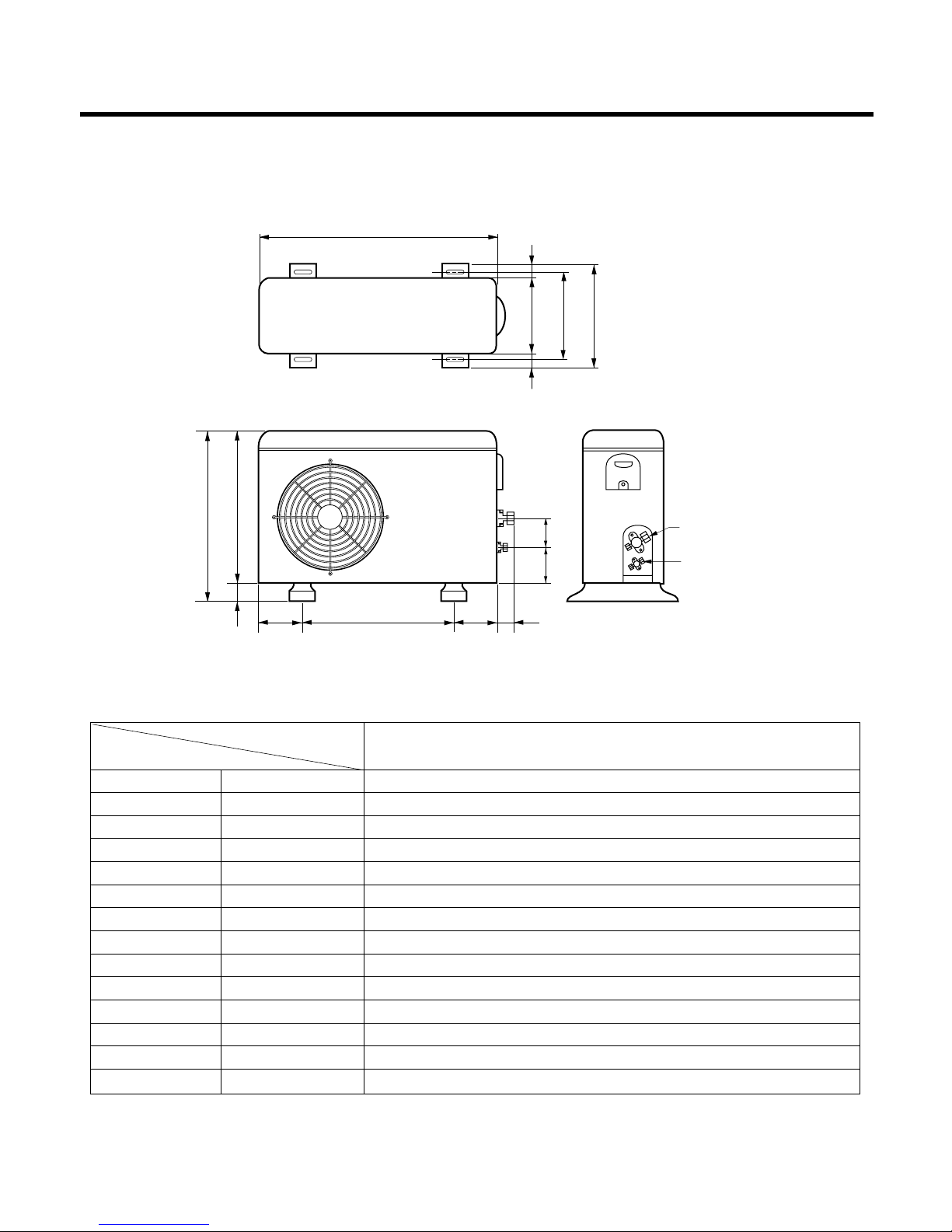
W
L7 L6 L8 L9
D
L1
L2
L3
L10L11
L4L5
H
Gas side
3-way valve
Liquid side
3-way valve
W mm 870
H mm 800
D mm 320
L1 mm 370
L2 mm 340
L3 mm 25
L4 mm 775
L5 mm 25
L6 mm 546
L7 mm 162
L8 mm 162
L9 mm 54
L10 mm 74.5
L11 mm 79
30K, 32K SERIES
(2) Outdoor Unit

-10-
320
790
385
72
482
4-ø12Hole
249
71
145
500
145
10
334
354
10
265
440
925
965
130
40
80
292.5
(Air intake vent)
(Air intake vent)
(Air intake vent)
36K SERIES
-11-
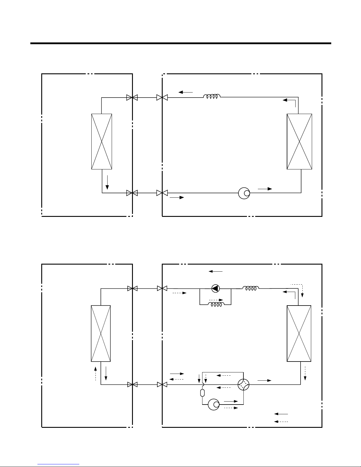
Refrigeration Cycle Diagram
INDOOR UNIT OUTDOOR UNIT
INDOOR UNIT OUTDOOR UNIT
HEAT
EXCHANGE
(EVAPORATOR)
HEAT
EXCHANGE
(EVAPORATOR)
HEAT
EXCHANGE
(CONDENSER)
HEAT
EXCHANGE
(CONDENSER)
COMPRESSOR
COMPRESSOR
ACCUMU
LATOR
GAS SIDE
GAS SIDE
3-WAY VALVE
LIQUID SIDE
LIQUID SIDE
3-WAY VALVE
CAPILLARY TUBE
CAPILLARY TUBE
CHECK VALVE
(Heating Model only)
COOLING
HEATING
REVERSING
VALVE
(Heating Model Only)
(1) Cooling Only Models
(2) Cooling & Heating Models
-12-
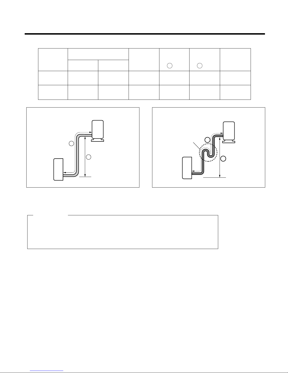
Pipe length and the elevation
* Capicity is based on standard length and maximum allowance length is the basis of
reliability.
* Oil trap should be installed per 5~7 meters.
CAUTION
Outdoor unit
Indoor unit
A
B
A
Oil trap
Outdoor unit
Indoor unit
B
In case more than 5m
30k/32k
5/8" 3/8" 7.5 15 30 30
(50Hz, 60Hz)
36k/38k
3/4" 3/8" 7.5 20 30 50
(50Hz, 60Hz)
Pipe Size
Capacity
(Btu/h)
GAS LIQUID
Additional
Refrigerant
(g/m)
Max.
Length
A (m)
Max.
Elevation
B (m)
Standard
Length
(m)
-13-
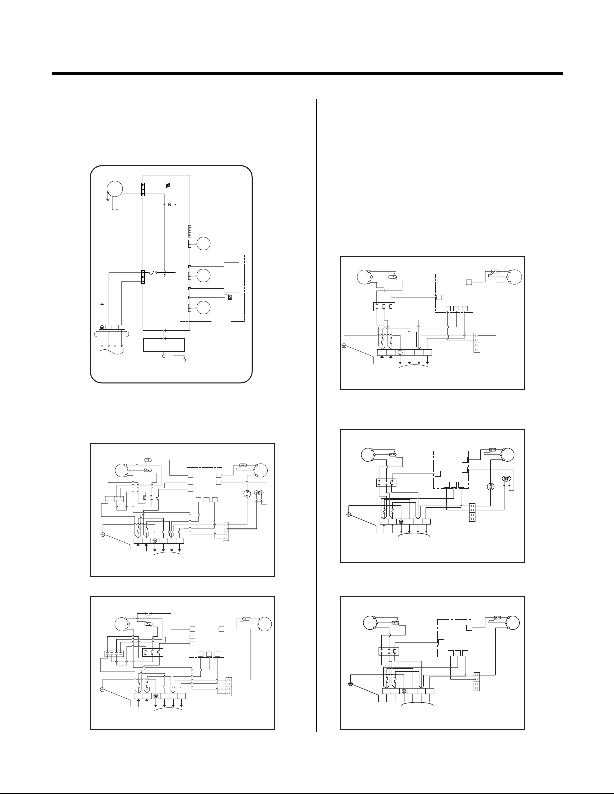
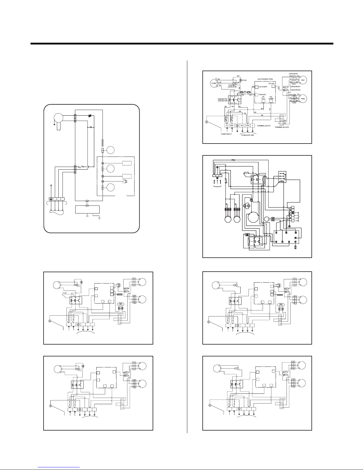
Wiring Diagram
3(L) 4(N)
START
CAPACITOR
BK
BL
RD
BR
R
S
COMP
RUNNING
CAPACITOR
BR
BR
BR
BR
BR
12
BL
1(L) 2(N)
TERMINAL BLOCK
BL
12
BK
BR
BL
BR
CN-
P2(N)
CN-COMP2
CN-COMP1
CN-FAN
OR
OR
BK
FAN
RY-CAPA
OUTDOOR PCB
CAPACITOR
YL
CNP1(L)
CN-
COMM
RD
BK
TERMINAL
BLOCK1
5
TO INDOOR UNIT
POWER INPUT
FUSE(5A)
FUSE(5A)
1
0
2
6
4
8
POWER
RELAY
TERMINAL
BLOCK 2
BR
BR
C
BK
OUTDOOR WIRING DIAGRAM
3854A20051B
OUTDOOR WIRING DIAGRAM
3854A20051D
OUTDOOR WIRING DIAGRAM
3854A20051F
OUTDOOR WIRING DIAGRAM
3854A20051G
BL
BL
BL
BR
OR
YL
FAN
BK
OR
CN-FAN
OUTDOOR PCB
RD
S
BL
RUNNING
C
BR
CN-CN-CN-
CN-COMP2
RD
P2(N)
COMM
P1(L)
BR
026
POWER
RELAY
148
CAPACITOR
R
COMP
2
BK
1
TERMINAL BLOCK1
TERMINAL BLOCK
5
4(N)3(L)
2(N)
1(L)
FUSE(5A)
FUSE(5A)
(COMM)
TO INDOOR UNIT
POWER INPUT
BR
CAPACITOR
BL
BK
BK
BL
BL
BR
YL
OR
FAN
OR
CAPACITOR
REVERSING
VALVE
BK
BK
SWITCH
HIGH PRESSURE
21
BK
OUTDOOR PCB
RUNNING
BL
S
C
COMP
BR
RD
R
CN-CN-
CN-COMP2
CN-
BR
RD
P2(N) P1(L)
COMM
RELAY
POWER
062
814
CAPACITOR
5
(COMM)
4(N)
TERMINAL BLOCK
1(L)
2(N)
FUSE(5A)
FUSE(5A)
3(L)
POWER INPUT
TO INDOOR UNIT
BR
TERMINAL BLOCK1
CN-4WAY
CN-FAN
3(L) 4(N)
START
CAPACITOR
BK
BL
RD
BR
R
S
COMP
RUNNING
CAPACITOR
BR
BR
BR
BR
BR
12
BL
1(L) 2(N)
TERMINAL BLOCK
BL
12
BK
BL
BR
CN-
P2(N)
CN-COMP2
CN-COMP1
CN-FAN
OR
OR
BK
REVERSING
VALVE
HIGH PRESSURE
S/W
BK
FAN
RY-CAPA
OUTDOOR PCB
CAPACITOR
YL
CN-4WAY
CN-
P1(L)
CN-
COMM
RD
BK
BK
TERMINAL
BLOCK1
5
TO INDOOR UNIT
POWER INPUT
FUSE(5A)
FUSE(5A)
1
0
2
6
4
8
POWER
RELAY
TERMINAL
BLOCK 2
BR
BR
C
BK
OUTDOOR WIRING DIAGRAM
3854A20051A
MOTOR
SH-CAPA.
YL
PILLAR
TERMINAL
AUTO RESTART
FORCED OPERATION
CN-DISP
CN-L/R CN-U/D CN-TH
THERMISTOR
STEP
MOTOR
(UP/DOWN)
STEP
MOTOR
(L/R)
H.V.B ASM
LIMITS S/W
Negative ion
OPTION
STEP
MOTOR
(L/R)
CN-L/R
DISPLAY PCB ASM
INDOOR WIRING DIAGRAM
3854A20065A
TO OUTDOOR UNIT
BL
3(L)
4(N) 5
BR
RD
GN/YL
BLRDBR
GN/YL
BR
FUSE
AC250V/T2A
TRIAC
OR
BK
ZNR
CN-POWER
CN-MOTOR
LS- M3060HL/CL/AL/BL, LS-M3061HL/CL/BL/AL
LS- M3064HL/CL/DL/DM/EM, LS-M3063CL
LS- M3221HL/CL/BL/AL, LS-M3021CL/AL
LS-M3064HL/EM, LS-M306LHL/LEL
LS-M3060HL, LS-M3061HL/BL,
LS-M3221HL/BL
LS-M3064CL/DL/DM, LS-M3063CL, LS-M306LCL/LDL
LS-M3060HL/BL, LS-M3061HL,
LS-M3221CL/AL, LS-M3021CL
LS-M3021AL, LS-M3061CL/AL
5
(COMM)
3(L) 4(N)
BL
RD
BR
R
S
COMP
RUNNING
CAPACITOR
BL
BL
BR
BL
1(L) 2(N)
TERMINAL BLOCK
BL
12
BK
BR
CN-
P2(N)
CN-COMP2
CN-FAN
OR
OR
FAN
OUTDOOR PCB
CAPACITOR
YL
CNP1(L)
CN-
COMM
RD
BK
TERMINAL BLOCK1
TO INDOOR UNIT
POWER INPUT
FUSE(5A)
FUSE(5A)
1
0
2
6
4
8
POWER
RELAY
BR
C
(2) Outdoor Unit
(Outdoor Unit - Continued)
• 30K, 32K
(1) Indoor Unit
-14-
MOTOR
SH-CAPA.
YL
PILLAR
TERMINAL
AUTO RESTART
FORCED OPERATION
CN-DISP
CN-L/R CN-U/D CN-TH
THERMISTOR
STEP
MOTOR
(UP/DOWN)
STEP
MOTOR
(L/R)
H.V.B ASM
LIMITS S/W
Negative ion
OPTION
STEP
MOTOR
(L/R)
CN-L/R
DISPLAY PCB ASM
INDOOR WIRING DIAGRAM
3854A20065A
TO OUTDOOR UNIT
BL
3(L)
4(N) 5
BR
RD
GN/YL
BLRDBR
GN/YL
BR
FUSE
AC250V/T2A
TRIAC
OR
BK
ZNR
CN-POWER
CN-MOTOR
LS-N3660HL/CL/AL/BL, LS-N3661HL/CL/AL/BL
LS-N3821HL/CL/BL/AL, LS-N3621CL/AL
LS-N3664EL/LS-N3621BL/LS-C366NLD0/LS-H366NLD0
LS-C366NLA0/LS-C366NLB0/LS-H366NMD0/LS-N3621HL
LS-N3660HL/BL, LS-N3661HL/BL, LS-H366NLD0
LS-N3821HL/BL, LS-N3621BL/HL
LS-N3664EL/LS-H366NMD0
LS-C366NLB0
LS-N3660CL, LS-N3661CL/AL, LS-C366NLD0, LS-C366NLA0
LS-N3821CL/AL, LS-N3621CL/AL
5
3(L) 4(N)
BK
RD
WH
WH
WH
R
S
COMP
RUNNING
CAPACITOR
BL
BL
BR
BR
BK
BK
BK
BK
WH
1(L) 2(N)
TERMINAL BLOCK
1
2
CN-P2(N)
CN-COMP2
CN-FAN
CN-4WAY
CN-TH
THERMISTOR
OR
OR
OROR
FAN1
OUTDOOR PCB
PTCR
MAGNECTIC
CONTACTOR
CRANK CASE
HEATER FOR COMP
CAPACITOR
YLYL
CN-
P1(L)
CN-
COMM
RD
BK BK
BK
BK
BK
BK
BK
BKBK
TERMINAL BLOCK1
TO INDOOR UNIT
POWER INPUT
FUSE(5A)
FUSE(5A)
T2 T1
L2 L1
A2
A1
BR
C
OUTDOOR WIRING DIAGRAM
3854A20051K
YL
FAN2
CAPACITOR1
CAPACITOR2
OR
YL
OR
REVERSING
VALVE
HIGH PRESS
SWITCH
OUTDOOR WIRING DIAGRAM
3854A20051L
OUTDOOR WIRING DIAGRAM
3854A20051M
5
3(L) 4(N)
BK
RD
WH
WH
WH
R
S
COMP
RUNNING
CAPACITOR
BL
BL
BR
BR
BK
BK
BK
BK
WH
1(L) 2(N)
TERMINAL BLOCK
1
2
CN-P2(N)
CN-COMP2
CN-FAN
OR
OROR
FAN1
OUTDOOR PCB
PTCR
MAGNECTIC
CONTACTOR
CAPACITOR
YLYL
CN-
P1(L)
CN-
COMM
RD
BK BK
BK
BK
BKBK
TERMINAL BLOCK1
TO INDOOR UNIT
POWER INPUT
FUSE(5A)
FUSE(5A)
T2 T1
L2 L1
A2
A1
BR
C
OUTDOOR WIRING DIAGRAM
3854A20051H
YL
FAN2
CAPACITOR1
CAPACITOR2
OR
YL
OR
5
3(L) 4(N)
BK
RD
WH
R
S
COMP
RUNNING
CAPACITOR
BL
BL
BR
BR
BK
BK
BK
BK
WH
1(L) 2(N)
TERMINAL BLOCK
1
2
CN-P2(N)
CN-COMP2
CN-FAN
OR
OROR
FAN1
OUTDOOR PCB
MAGNECTIC
CONTACTOR
CAPACITOR
YLYL
CN-
P1(L)
CN-
COMM
RD
BK BK
BK
BK
BKBK
TERMINAL BLOCK1
TO INDOOR UNIT
POWER INPUT
FUSE(5A)
FUSE(5A)
T2 T1
L2 L1
A2
A1
BR
C
OUTDOOR WIRING DIAGRAM
3854A20051J
YL
FAN2
CAPACITOR1
CAPACITOR2
OR
YL
OR
OUTDOOR WIRING DIAGRAM
3854A20051Z
78
1
TM
220-240V
1Ø, 50Hz
POWER SUPPLY
BK(BR)
63H2
52C
L1
L2
T1 T2
A2
A1
BK(BR)
52F1
12
34
56
WH
BK
BK
BK
BL
BR
WH
F1
BK(BR)
BK(BR)
WH(BL)
WH
Co
OR YLCoOR
FMo1
49FMo
CN-POWER2(N)
CN-POWER1(L)
CN-RYOIM CN-4WAY CN-COMP2
THERMISTOR
CN-TH
CN-COM
CN-FAN
FMo2
49FMo
20SV
YL
BKBK
BK
WH(BL)
BK(BR)
WH(BL)
BKBKBK
BL BK
BK
BKBK
WH
WH
BK
WH
YL
52S
BR
BL
BK
RD
GN/YL
PCB
Tmo
To indoor unit
WH(BL)
GN/YL
23
LN
1
2
3(L)
4(N)
5
CH1
BK
BK
BK
YL
BK
RD
BK
RD
REACTOR
R
C
S
CM
Cr
Cs
A2A1T3L3T2
L2
5
3(L) 4(N)
BK
RD
WH
R
S
COMP
RUNNING
CAPACITOR
BL
BL
BR
BR
BK
BK
BK
BK
WH
1(L) 2(N)
TERMINAL BLOCK
1
2
CN-P2(N)
CN-COMP2
CN-FAN
CN-4WAY
CN-TH
THERMISTOR
OR
OR
OROR
FAN1
OUTDOOR PCB
MAGNECTIC
CONTACTOR
CAPACITOR
YLYL
CN-
P1(L)
CN-
COMM
RD
BK BK
BK
BK
BK
BK
BK
BKBK
TERMINAL BLOCK1
TO INDOOR UNIT
POWER INPUT
FUSE(5A)
FUSE(5A)
T2 T1
L2 L1
A2
A1
BR
C
YL
FAN2
CAPACITOR1
CAPACITOR2
OR
YL
OR
REVERSING
VALVE
HIGH PRESS
SWITCH
(2) Outdoor Unit
• 36K, 38K
(1) Indoor Unit

1. MAIN UNIT FUNCTION
• DISPLAY
1) C/O Model (high quality LCD remote controller supplied)
Op
eration
Indicato
r
• On while in appliance operation, off while in appliance pause
Ti
mer Indicator
• On while in timer mode (on/off) and in sleep timer mode, off when timer mode is completed or canceled.
Comp. Running Indicator
• While in appliance operation, on while in outdoor unit compressor running, off while in compressor off
P
lasma Indicator
• On while in plasma mode, off while plasma mode is canceled.
Auto restart Indicator
• On while auto restart mode, off while auto restart mode is canceled.
Auto restart
• In case the power comes on again after a power failure, Auto Restarting Operation is the function to operate
procedures automatically to the previous operating conditions.
If your want to use this operation, press the Auto Restart Button.
Power(Forced Operation)
• Operation starts, when this button is pressed and stops when you press the button again.
2) H/P Model (high quality LCD remote controller supplied)
Operation Indicator
• On while in appliance operation, off while in appliance pause
Timer Indicator
• On while in timer mode (on/off) and in sleep timer mode, off when timer mode is completed or canceled
D
efrost Indicator
• Off except when hot start during heating mode operation or while in defrost control.
P
lasm
a Indicator
• On while in plasma mode, off while plasma mode is canceled.
Auto restart Indicator
• On while auto restart mode, off while auto restart mode is canceled.
Auto restart
• In case the power comes on again after a power failure, Auto Restarting Operation is the function to operate
procedures automatically to the previous operating conditions.
If your want to use this operation, press the Auto Restart Button.
Power(Forced Operation)
• Operation starts, when this button is pressed and stops when you press the button again.
■ Cooling Mode Operation
•
When the intake air temperature reaches 0.5°C below the setting temp, the compressor and the outdoor fan stop.
• When it reaches 0.5°C above the setting temp, they start to operate again.
Compressor ON Temp=> Setting Temp+0.5°C
Compressor OFF Temp => Setting Temp-0.5°C
• While in compressor running, operating with the airflow speed set by the remote controller. While in compressor
not running, operating with the low airflow speed regardless of the setting.
-15-
Operation Details

■
Healthy Dehumidification Mode
• When the dehumidification operation input by the remote controller is received, the intake air temperature is
detected and the setting temp is automatically set according to the intake air temperature.
26°C ≤ Intake Air Temp => 25°C
24°C ≤ Intake Air Temp < 26°C => Intake Air Temp-1°C
18°C ≤ Intake Air Temp < 24°C => Intake Air Temp-0.5°C
Intake Air Temp < 18°C=>18°C
• While in compressor off, the indoor fan repeats low airflow speed and pause.
• While the intake air temp is between compressor on temp. and compressor off temp., 10-min dehumidification
operation and 4-min compressor off repeat
Compressor ON Temp. => Setting Temp+0.5°C
Compressor OFF Temp. => Setting Temp-0.5°C
• In 10-min dehumidification operation, the indoor fan operates with the low airflow speed.
■
Heating Mode Operation
• When the intake air temp reaches +3°Cabove the setting temp, the compressor is turned off. When below the
setting temp, the compressor is turned on.
Compressor ON Temp. => Setting Temp.
Compressor OFF Temp. => Setting Temp.+3°C
• While in compressor on, the indoor fan is off when the indoor pipe temp. is below 26®¨C , when above 28°C,it
operates with the low or setting airflow speed (while in sleep mode, with the medium airflow speed).
• While in compressor off, the indoor fan is off when the indoor pipe temp is below 33°C , when above 35°C,it
operates with the low airflow speed.
• If overloaded while in heating mode operation, in order to prevent the compressor from OLP operation, the outdoor fan is turned on/off according to the indoor pipe temp.
• While in defrost control, both of the indoor and outdoor fans are turned off.
■
Defrost Control
• While in heating mode operation in order to protect the evaporator pipe of outdoor unit from freezing, reversed
to cooling cycle to defrost the evaporator pipe of the outdoor unit.
• Defrost control is available 30 minutes later since heating mode operation started, and it will not polong over 6
minutes.
•
Deicing starts only when the outdoor pipe temperature falls below -6°C after 30 minutes passed from starting of
heating operating and more than 10 minutes operation of compressor.
• Deicing ends after 6 minutes passed from starting of deice operation or when the outdoor pipe temperature rises
over 12°C even if before 6 minutes.
■ Fuzzy Operation (C/O Model)
• According to the temperature set by Fuzzy rule, when the intake air temp is 0.5°C or more below the setting
temp, the compressor is turned off. When 0.5°C or more above the setting temp, the compressor is turned on.
Compressor ON Temp => Setting Temp+0.5°C
Compressor OFF Temp => Setting Temp+0.5°C
• At the beginning of Fuzzy mode operation, the setting temperature is automatically selected according to the
intake air temp at that time.
-16-

26°C ≤ Intake Air Temp => 25°C
24°C ≤ Intake Air Temp<26°C => Intake Air Temp+1°C
22°C ≤ Intake Air Temp<24°C => Intake Air Temp+0.5°C
18°C ≤ Intake Air Temp<22°C => Intake Air Temp
Intake Air Temp<18°C=>18°C
• When the Fuzzy key (Temperature Control key) is input after the initial setting temperature is selected, the
Fuzzy key value and the intake air temperature at that time are compared to select the setting temperature
automatically according to the Fuzzy rule.
• While in Fuzzy operation, the airflow speed of the indoor fan is automatically selected according to the temperature
■ Fuzzy Operation (H/P Model)
• When any of operation mode is not selected like the moment of the power on or when 3 hrs has passed since
the operation off, the operation mode is selected.
• When determining the operation mode, the compressor, the outdoor fan, and the 4 way valve are off and only
the indoor fan is operated for 15 seconds. Then an operation mode is selected according to the intake air temp
at that moment as follows.
24°C ≤ Inatake Air Temp => Fuzzy Operation for Cooling
21°C ≤ Inatake Air Temp<24°C => Fuzzy Operation for Dehumidification
Inatake Air Temp<21°C => Fuzzy Operation for Heating
• If any of the operation modes among cooling / dehumidification / heating mode operations is carried out for 10
sec or longer before Fuzzy operation, the mode before Fuzzy operation is operated.
1) Fuzzy Operation for Cooling
• According to the setting temperature selected by Fuzzy rule, when the intake air temp is 0.5°C or more below
the setting temp, the compressor is turned off. When 0.5°C or more above the setting temp, the compressor is
turned on.
Compressor ON Temp => Setting Temp+0.5°C
Compressor OFF Temp => Setting Temp+0.5°C
• At the beginning of Fuzzy mode operation, the setting temperature is automatically selected according to the
intake air temp at that time.
26°C ≤ Intake Air Temp => 25°C
24°C ≤ Intake Air Temp<26°C => Intake Air Temp+1°C
22°C ≤ Intake Air Temp<24°C => Intake Air Temp+0.5°C
18°C ≤ Intake Air Temp<22°C => Intake Air Temp
Intake Air Temp < 18°C=>18°C
• When the Fuzzy key (Temperature Control key) is input after the initial setting temperature is selected, the
Fuzzy key value and the intake air temperature at that time are compared to select the setting temperature
automatically according to the Fuzzy rule.
• While in Fuzzy operation, the airflow speed of the indoor fan is automatically selected according to the temperature.
2) Fuzzy Operation for Dehumidification
• According to the setting temperature selected by Fuzzy rule, when the intake air temp is 0.5°C or more below
the setting temp, the compressor is turned off. When 0.5°C or more above the setting temp, the compressor is
turned on.
-17-

Compressor ON Temp => Setting Temp+0.5°C
Compressor OFF Temp => Setting Temp+0.5°C
• At the beginning of Fuzzy mode operation, the setting temperature is automatically selected according to the
intake air temp at that time.
26°C ≤ Intake Air Temp => 25°C
24°C ≤ Intake Air Temp<26°C => Intake Air Temp+1°C
22°C ≤ Intake Air Temp<24°C => Intake Air Temp+0.5°C
18°C ≤ Intake Air Temp<22°C => Intake Air Temp
Intake Air Temp < 18°C=>18°C
• When the Fuzzy key (Temperature Control key) is input after the initial setting temperature is selected, the
Fuzzy key value and the intake air temperature at that time are compared to select the setting temperature
automatically according to the Fuzzy rule.
• While in Fuzzy operation, the airflow speed of the indoor fan repeats the low airflow speed or pause as in dehumidification operation.
3) Fuzzy Operation for Heating
• According to the setting temperature selected by Fuzzy rule, when the intake air temp is 3°C or more above the
setting temp, the compressor is turned off. When below the setting temp, the compressor is turned on.
Compressor ON Temp => Setting Temp
Compressor OFF Temp => Setting Temp + 3°C
• At the beginning of Fuzzy mode operation, the setting temperature is automatically selected according to the
intake air temp at that time.
20°C ≤ Intake Air Temp => Intake Air Temp + 0.5°C
Intake Air Temp < 20°C=>20°C
• When the Fuzzy key (Temperature Control key) is input after the initial setting temperature is selected, the
Fuzzy key value and the intake air temperature at that time are compared to select the setting temperature
automatically according to the Fuzzy rule.
• While in Fuzzy operation, the airflow speed of the indoor fan is set to the high or the medium according to the
intake air temperature and the setting temperature.
■ Airflow Speed Selection
• The airflow speed of the indoor fan is set to high, medium, low, or chaos by the input of the airflow speed selection key on the remote controller.
■ On-Timer Operation
• When the set time is reached after the time is input by the remote controller, the appliance starts to operate.
• The timer LED is on when the on-timer is input. It is off when the time set by the timer is reached.
• If the appliance is operating at the time set by the timer, the operation continues.
■ Off-Timer Operation
• When the set time is reached after the time is input by the remote controller, the appliance stops operating.
• The timer LED is on when the off-timer is input. It is off when the time set by the timer is reached.
• If the appliance is on pause at the time set by the timer, the pause continues.
-18-

■ Off-Timer <=> On-Timer Operation
• When the set time is reached after the on/off time is input by the remote controller, the on/off-timer operation is
carried out according to the set time.
■
Sleep Timer Operation
• When the sleep time is reached after <1,2,3,4,5,6,7,0(cancel) hr> is input by the remote controller while in
appliance operation, the operation of the appliance stops.
• While the appliance is on pause, the sleep timer mode cannot be input.
• While in cooling mode operation, 30 min later since the start of the sleep timer, the setting temperature increas-
es by 1°C After another 30 min elapse, it increases by 1°C again.
• When the sleep timer mode is input while in cooling cycle mode, the airflow speed of the indoor fan is set to the
low.
• When the sleep timer mode is input while in heating cycle mode, the airflow speed of the indoor fan is set to the
medium.
■ Chaos Swing Mode
• By the Chaos Swing key input, the vane automatically operates with the Chaos Swing or they are fixed to the
desired direction.
■ Chaos Natural Wind Mode
• When the Chaos Natural Wind mode is selected and then operated, the high, medium, or low speed of the airflow mode is operated for 2~15 sec randomly by the Chaos Simulation.”
■
Jet Cool Mode Operation (C/O Model)
• If the Jet Cool key is input at any operation mode while in appliance operation, the Jet Cool mode operates.
• In the Jet Cool mode, the indoor fan is operated at super-high speed for 30 min at cooling mode operation.
• In the Jet Cool mode operation, the room temperature is controlled to the setting temperature, 18°C
• When the sleep timer mode is input while in the Jet Cool mode operation, the Jet Cool mode has the priority.
• When the Jet Cool key is input, the upper/lower vanes are reset to those of the initial cooling mode and then
operated in order that the air outflow could reach further.
■ Jet Cool Mode Operation (H/P Model)
• While in heating mode or Fuzzy operation, the Jet Cool key cannot be input. When it is input while in the other
mode operation (cooling, dehumidification, ventilation), the Jet Cool mode is operated.”
• In the Jet Cool mode, the indoor fan is operated at super-high speed for 30 min at cooling mode operation.
• In the Jet Cool mode operation, the room temperature is controlled to the setting temperature, 18°C
• When the sleep timer mode is input while in the Jet Cool mode operation, the Jet Cool mode has the priority.
• When the Jet Cool key is input, the upper/lower vanes are reset to those of the initial cooling mode and then
operated in order that the air outflow could reach further.
■ Auto Restarting Operation
• When the power is restored after a sudden power failure while in appliance operation, the mode before the
power failure is kept on the memory and the appliance automatically operates in the mode on the memory.
-19-

• Operation Mode that is kept on the memory
- State of Operation ON/OFF
- Operation Mode/Setting Temp/Selected Airflow Speed
- Sleep Timer Mode/Remaining Time of Sleep Timer (unit of hour)
■ Forced Operation ( C/O Model)
• To operate the appliance by force in case that the remote controller is lost, the forced operation button is on the
main unit of the appliance to operate the appliance in the standard conditions.
• Press the forced operation button, the forced operation is carried out.
• Press the forced operation button once again to stop operation.
• The forced operation is carried out in cooling mode with the setting temperature 22°C and the high speed of air-
flow.
■ Forced Operation ( H/P Model)
• To operate the appliance by force in case that the remote controller is lost, the forced operation selection switch
is on the main unit of the appliance to operate the appliance in the standard conditions.
• Press the forced operation button, the forced operation is carried out.
• Press the forced operation button once again to stop operation.
• In the forced operation mode, the indoor fan is operated at low speed for around 15 sec and then the operation
condition is set according to the intake air temperature as follows.
24°C ≤ Intake Air Temp => Cooling Mode Operation, 22°C, High Speed
21°C ≤ Intake Air Temp < 24°C => Dehumidification Operation, 23°C, High Speed
Intake Air Temp < 21°C => Heating Mode Operation, 24°C, High Speed
■ Test Operation Control
• To check the condition of the installation when installing the appliance, the appliance is operated at cooling
mode, high speed of airflow, compressor-on for 18 min without controlling the room temperature.
• After supplying power to the main body, keep pressing the forced operation button for about 3 seconds.
• While in test operation, a key can be input by the remote controller.
When a key (operation start/stop, operation mode selection, airflow speed selection, temperature control, Jet
Cool) is input by the remote controller, the test operation is canceled and the appliance is operated according to
the setting by the remote controller.
■ Protection of the evaporator pipe from frosting
• In the temperrature of the indoor pipe is below 0°C after 7 minutes from starting the compressor, the compressor and outdoor fan are stopped, and 3 minutes delay of operating of the compressor, when the temperature of
the indoor pipe is over 7°C, the compressor and the outdoor fan are reoperated.
• Outdoor fan motor stops when indoor pipe temperature is blow 3°C and restarts at the pipe temperature above
6°C or after 90 seconds, if the pipe temperature does not rise to 6°C, outdoor fan motor runs continuously at
even below 3°C.
■ Buzzer Sounding Operation
• When the appliance-operation key is input by the remote controller, the short “beep-beep-” sounds.
• When the appliance-pause key is input by the remote controller, the long “beep—” sounds.
-20-

■ Air Cleaner Operation
• When an air cleaner function is selected during Air Conditioner operation
- Plasma air cleaner function will be operated while in any operation mode with selecting the function.
- The function is to be stopped while it is operating with selecting the function.
• When an air cleaner function is selected during operation off
- The function will be only operated.
• When inlet grille of air conditioner is opened during plasma operation, High Voltage Generator(H.V.B) is to be
stopped. When inlet grille of air conditioner is closed during plasma operation, High Voltage Generator(H.V.B)
will be operated again.
-21-
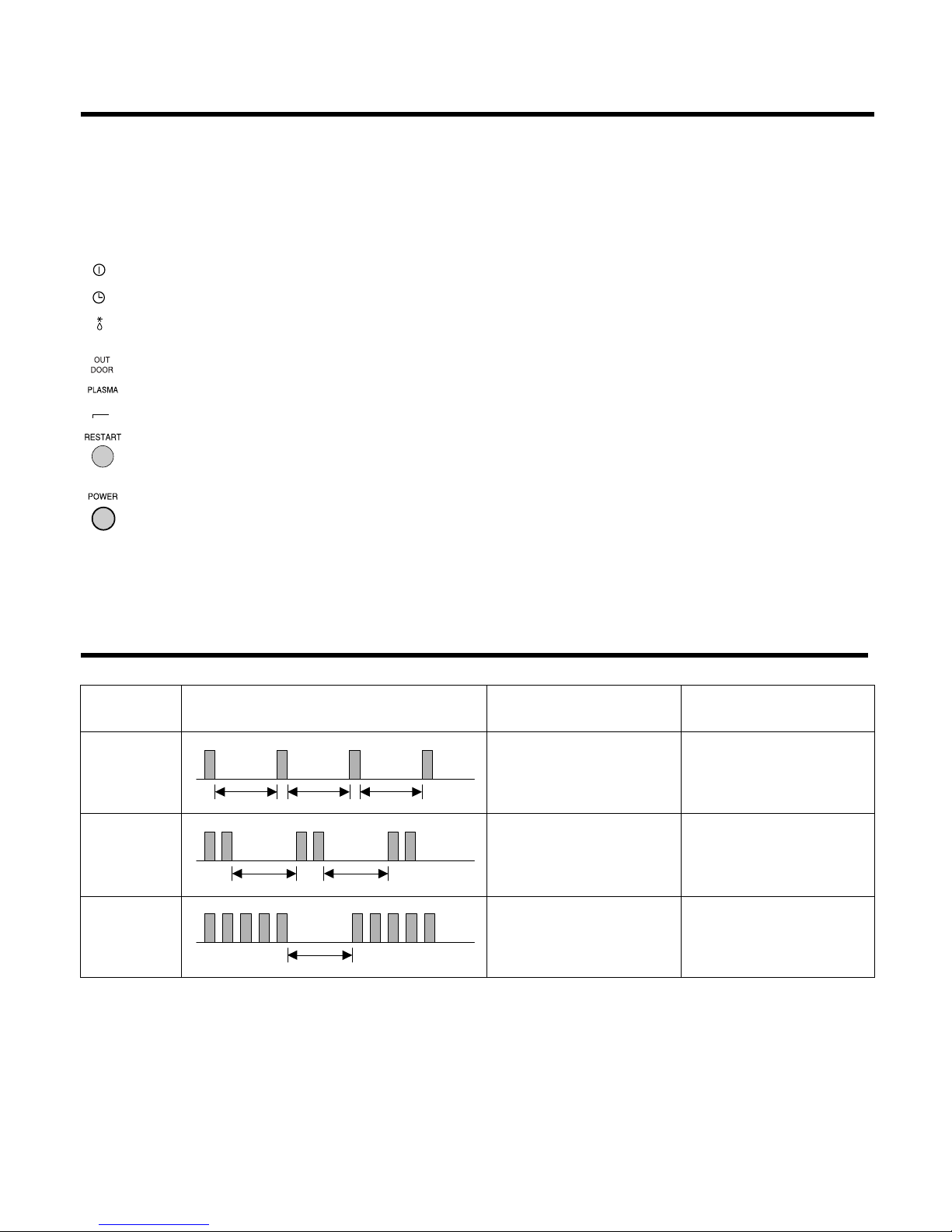
-22-
Display Function
Self-diagnosis Function
Signal Receptor
Receives the signals from the remote control.(Signal receiving sound: two short beeps or one long beep.)
Operation Indication Lamps
On/Off : Lights up during the system operation.
Timer or Sleep Mode : Lights up during Timer operation or Sleep mode.
Defrost Mode : Lights up during Defrost Mode or Hot
Start operation. (Heat pump model only)
Outdoor unit operation : Lights up during outdoor unit operation. (Cooling model only)
Plasma Mode : Lights up during plasma-purification operation.(option)
Auto Restart Mode : Lights up during if Restart Button is pressed.
Auto Restart Button : In failure of electric power, if the button is pressed the unit runs as previous
setting operation when power returns.
Forced Operation Button
: Operation starts, when this button is pressed and stops when you press the
button again.
3sec 3sec 3sec
(once)
3sec 3sec
(twice)
3sec
(5times)
Error
Code
1
2
5
Error LED
(Indoor body operation LED)
Error contents
• Indoor room temperature
thermistor open/short
• Indoor pipe temperature
thermistor open/short.
• Outdoor pipe temperature
thermistor open/short.
• Poor communication.
• Indoor TH assy check
• Outdoor TH assy check
• Communication line/circuit
check
SVC check point
-23-
Installation
Read completely, then follow step by step.
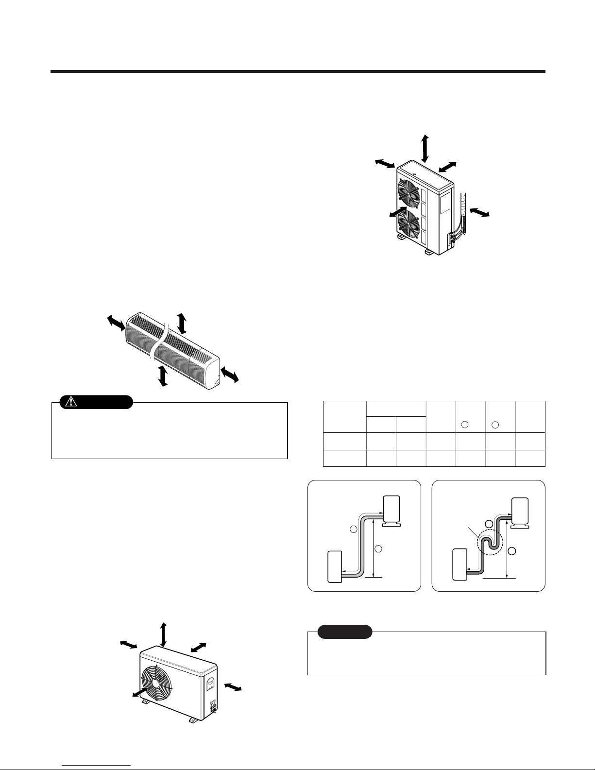
1. Installation of Indoor, Outdoor unit
1) Select the best location
1. Indoor unit
■ Do not have any heat or steam near the unit.
■ Select a place where there are no obstacles in
front of the unit.
■ Make sure that condensation drainage can be
conveniently routed away.
■ Do not install near a doorway.
■ Ensure that the space around the left and right of
the unit is more than 30cm. The unit should be
installed as high on the wall as possible, allowing
a minimum of 12cm from ceiling.
■ Use a stud finder to locate studs to prevent
unnecessary damage to the wall.
2. Outdoor unit
■ If an awning is built over the unit to prevent direct sun-
light or rain exposure, make sure that heat radiation
from the condenser is not restricted.
■ Ensure that the space around the back and sides is
more than 10cm. The front of the unit should have
more than 70cm of space.
■ Do not place animals and plants in the path of the
warm air.
■ Take the air conditioner weight into account and select
a place where noise and vibration are minimum.
■ Select a place so that the warm air and noise from the
air conditioner do not disturb neighbors.
■ Rooftop Installations:
If the outdoor unit is installed on a roof structure, be
sure to level the unit. Ensure the roof structure and
anchoring method are adequate for the unit location.
Consult local codes regarding rooftop mounting.
If the outdoor unit is installed on root structures or walls,
this may result in excessive noise and vibration, and
maybe also classed as non serviceable installation.
2) Piping length and elevation
More than 12cm
More than
30cm
More than
30cm
More than 2.3m
More than 10cm More than 10cm
More
than 60cm
More than 60cm
More than 70cm
More than 10cm More than 10cm
More
than 60cm
More than 60cm
More than 70cm
In case more than 5m
• Capacity is based on standard length and maximum
allowance length is on the basis of reliability.
• Oil trap should be installed every 5~7 meters.
Outdoor unit
Indoor unit
A
B
A
Oil trap
Outdoor unit
Indoor unit
B
CAUTION
Install the indoor unit on the wall where the height
from the floors more than 2.3 meters.
A minimum pipe run of 7.5 meters is required to minimise vibration & excessive noise.
CAUTION
30k, 32k 5/8" 3/8" 7.5 15 30 30
36k, 38k 3/4" 3/8" 7.5 20 30 50
Pipe Size
Capacity
(Btu/h)
GAS LIQUID
Max.
length
A (m)
Additional
Refrigerant
(g/m)
Max.
Elevation
B
(m)
Standard
Length
(m)
30K, 32K
36K, 38K

-24-
3) How to fix installation plate
The wall you select should be strong and solid enough to prevent
vibration
1. Mount the installation plate on the wall with four
type A screws. If mounting the unit on a concrete
wall, use anchor bolts.
Mount the installation plate horizontally by
aligning the centerline using a level.
2. Measure the wall and mark the centerline. It is also
important to use caution concerning the location
of the installation plate-routing of the wiring to
power outlets is through the walls typically.
Drilling the hole through the wall for piping connections must be done safely.
5-7mm
(0.2~0.3")
Indoor
WALL
Outdoor
Installation Plate
Type "A" screw
Right rear pipingLeft rear piping
ø
70mm195mm
115mm
115mm
180mm
Right rear piping
30K, 32K
36K, 38K
Left rear piping
50mm
ø
70mm180mm
115mm
4) Drill a hole in the wall
■ Drill the piping hole with a ø70mm hole core drill.
Drill the piping hole at either the right or the left
with the hole slightly slanted to the outdoor side.
-25-
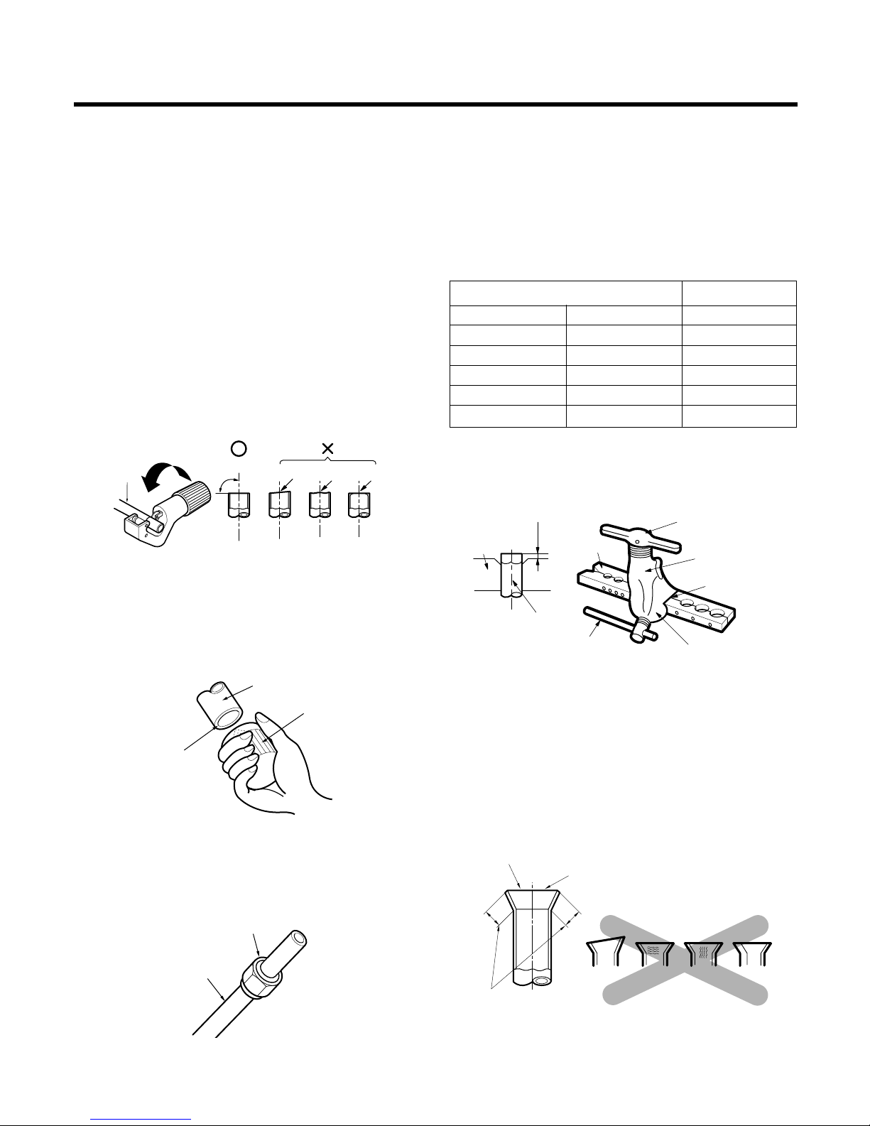
1) Flaring work
Main cause for gas leakage is due to defect in flaring work. Carry out correct flaring work in the following procedure.
1. Cut the pipes and the cable.
■ Use the piping kit accessory or the pipes
purchased locally.
■ Measure the distance between the indoor and the
outdoor unit.
■ Cut the pipes a little longer than measured
distance.
■ Cut the cable 1.5m longer than the pipe length.
2. Burrs removal
■ Completely remove all burrs from the cut cross
section of pipe/tube.
■ Put the end of the copper tube/pipe in a downward direction as you remove burrs in order to
avoid dropping burrs into the tubing.
3. Putting nut on
■ Remove flare nuts attached to indoor and outdoor
unit, then put them on pipe/tube having completed burr removal.
(not possible to put them on after flaring work)
Copper
pipe
90°
Slanted Uneven Rough
Bar
Copper pipe
Clamp handle
Red arrow mark
Cone
Yoke
Handle
Bar
"A"
Pipe
Reamer
Point down
4. Flaring work
■ Carry out flaring work using flaring tool as shown
below.
Firmly hold copper pipe in a die in the dimension
shown in the table above.
5. Check
■ Compare the flared work with figure below.
■ If flare is noted to be defective, cut off the flared
section and do flaring work again.
mm inch mm
ø6.35 1/4 0 ~ 0.5
ø9.52 3/8 0 ~ 0.5
ø12.7 1/2 0 ~ 0.5
ø15.88 5/8 0 ~ 1.0
ø19.05 3/4 1.0 ~ 1.3
Outside diameter A
Flare nut
Copper tube
Inclined
Inside is shiny without scratches
Smooth all round
Even length
all round
Surface
damaged
Cracked Uneven
thickness
= Improper flaring =
2. Flaring Work and Connection of Piping
-26-
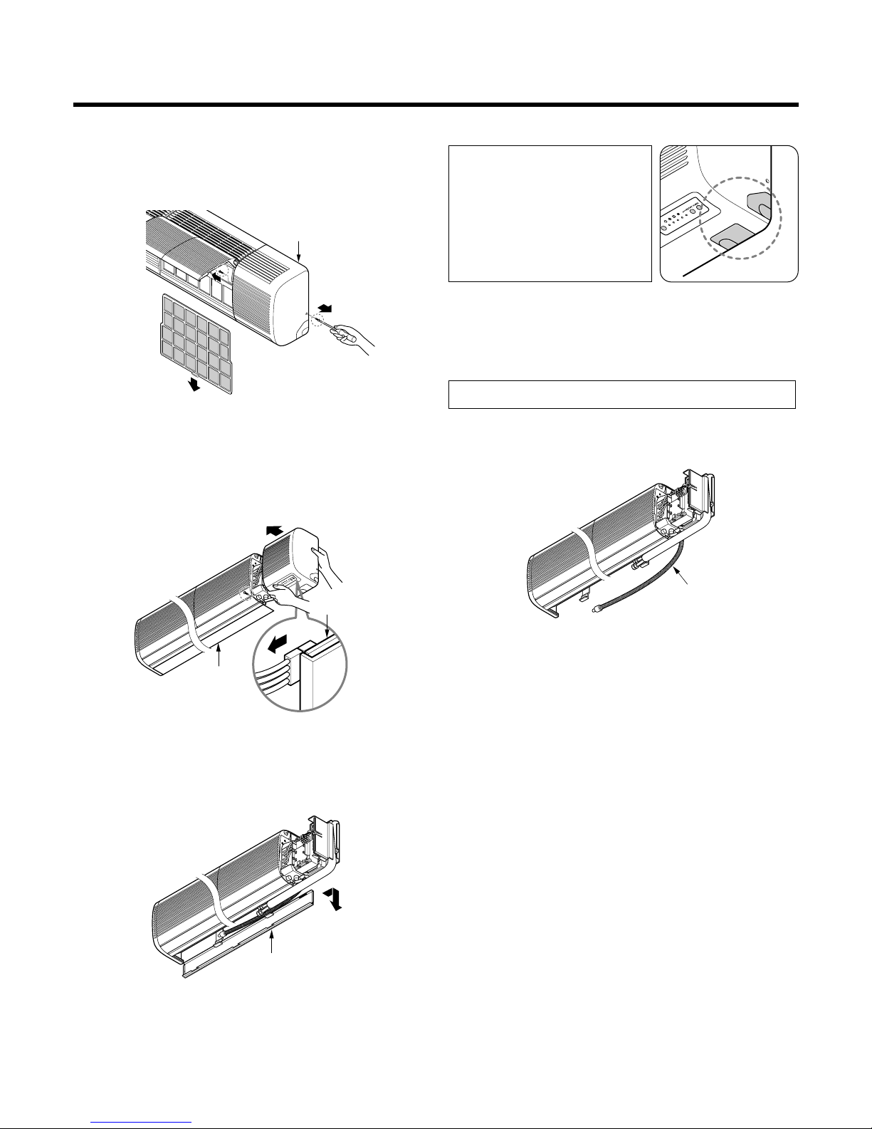
2) Connection of piping-Indoor
1. Remove the 2 screws of right side panel.
2. Remove the front right side panel by the arrow.
■ The connector can be disconnected by pulling it
while pressing the connector's hook.
■ Remove the 1 screw for fixing lower panel.
3. Remove the lower panel by the arrow.
■ Take care not to scratch the wall and mat to
drop.
1. Route the indoor tubing and the drain hose in the
direction of rear left.
2. Insert the connecting cable into the indoor unit
from the outdoor unit through the piping hole.
■ Do not connect the cable to the indoor unit.
■ Make a small loop with the cable for easy
connection later.
Right side panel
Drain hose
Main PCB
Lower panel
Lower panel
For left rear piping
CAUTION
When install, make sure that the
remaining parts must be
removed clearly so as not to
damage the piping and drain
hose, especially power cord and
connecting cable.
-27-
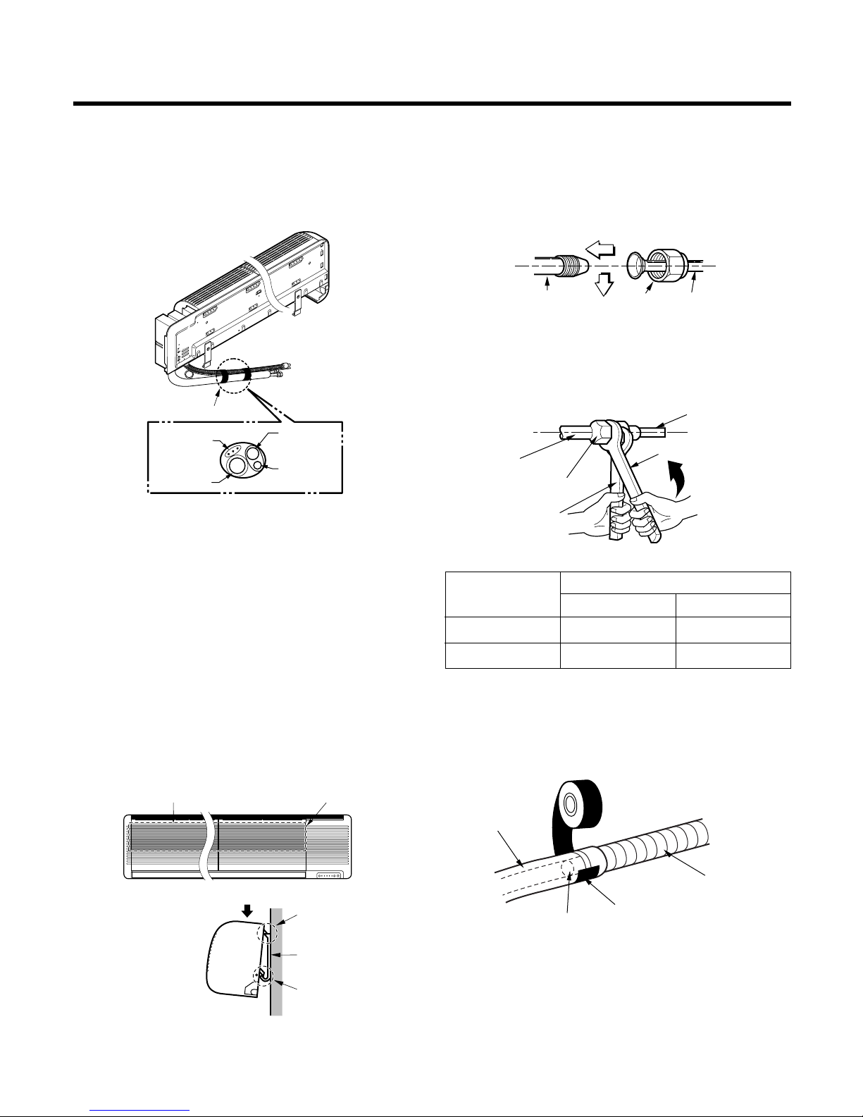
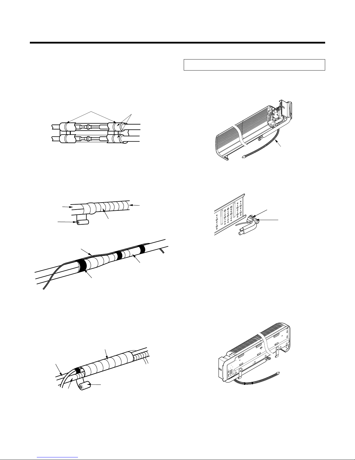
3. Tape the tubing, drain hose and the connecting
cable. Be sure that the drain hose is located at the
lowest side of the bundle. Locating at the upper side
can cause drain pan to overflow inside the unit.
3. Tape the tubing, drain hose and the connecting
cable. Be sure that the drain hose is located at the
lowest side of the bundle. Locating at the upper side
can cause drain pan to overflow inside the unit.
NOTE: If the drain hose is routed inside the room,
insulate the hose with an insulation material*
so that dripping from "sweating"(condensation) will not damage furniture or floors.
*Foamed polyethylene or equivalent is rec-
ommended.
4. Indoor unit installation
■ Hook the indoor unit onto the upper portion of the
installation plate.(Engage the three hooks of the
rear top and rear lower of the indoor unit with the
upper edge and lower edge of the installation
plate.) Ensure that the hooks are properly seated
on the installation plate by moving it left and right.
5. Connecting the pipings to the indoor unit and drain
hose to drain pipe.
■ Align the center of the pipings and sufficiently
tighten the flare nut by hand.
■ Tighten the flare nut with a wrench.
■ When extending the drain hose at the indoor unit,
install the drain pipe.
Connecting
cable
Loop
Gas side
piping
Liquid side
piping
Drain hose
Installation
plate
Three upper
hooks
Installation plate
Indoor unit
Three lower
hooks
Setting line
Indoor unit tubing Flare nut Pipings
Connection pipe
Flare nut
Indoor unit tubing
Torque wrench
Spanner (fixed)
Vinyl tape(narrow)
Adhesive
Drain pipe
Indoor unit drain hose
Pipe Size[Torque]
Capacity
(Btu/h)
GAS LIQUID
30K, 32K 5/8"[6.6kg.m] 3/8"[4.2kg.m]
36K, 38K 3/4"[6.6kg.m] 3/8"[4.2kg.m]
-28-
6. Wrap the insulation material around the connecting
portion.
■
Overlap the connection pipe insulation material and
the indoor unit pipe insulation material. Bind them
together with vinyl tape so that there is no gap.
■ Wrap the area which accommodates the rear piping housing section with vinyl tape.
■ Bundle the piping and drain hose together by
wrapping them with vinyl tape over the range within which they fit into the rear piping housing section.
1. Route the indoor tubing and the drain hose to the
required piping hole position.
2. Insert the piping, drain hose and the connecting
cable into the piping hole.
3. Insert the connecting cable into the indoor unit.
■ Don't connect the cable to the indoor unit.
■ Make a small loop with the cable for easy
connection later.
4. Tape the drain hose and the connecting cable.
• Connecting cable
Plastic bands
Insulation material
Drain hose
Drain pipe
Connecting cable
Vinyl tape(narrow)
Connection
pipe
Connecting cable
Vinyl tape
(wide)
Wrap with vinyl tape
Indoor
unit pipe
Pipe
Wrap with vinyl tape
Drain hose
Pipe
Vinyl tape(wide)
For right rear piping
 Loading...