

LG LS-K1820HM, LS-K1820CN, LS-K1820HN, LS-K1822CM, LS-K1822CN Service Manual
...
Room Air Conditioner
SERVICE MANUAL
MODEL : LS-K1820CL/CM/CN/HL/HM/HN
LS-K1822CL/CM/CN/HL/HM/HN
LS-K1860CL/CM/CN/HL/HM/HN
LS-K1861CL/CM/CN/HL/HM/HN
LS-K1862CL/CM/CN/HL/HM/HN
LS-K1865CL/CM/CN/HL/HM/HN
LS-K1866CL/CM/CN/HL/HM/HN
LS-K2460CL/CM/CN/HL/HM/HN
LS-K2462CL/CM/CN/HL/HM/HN
LS-K2420CL/CM/CN/HL/HM/HN
LS-K2422CL/CM/CN/HL/HM/HN
LS-K2621CL/CM/CN/HL/HM/HN
LS-K2661CL/CM/CN/HL/HM/HN
LS-K2662CL/CM/CN/HL/HM/HN
LS-K1863DL

- 2 -
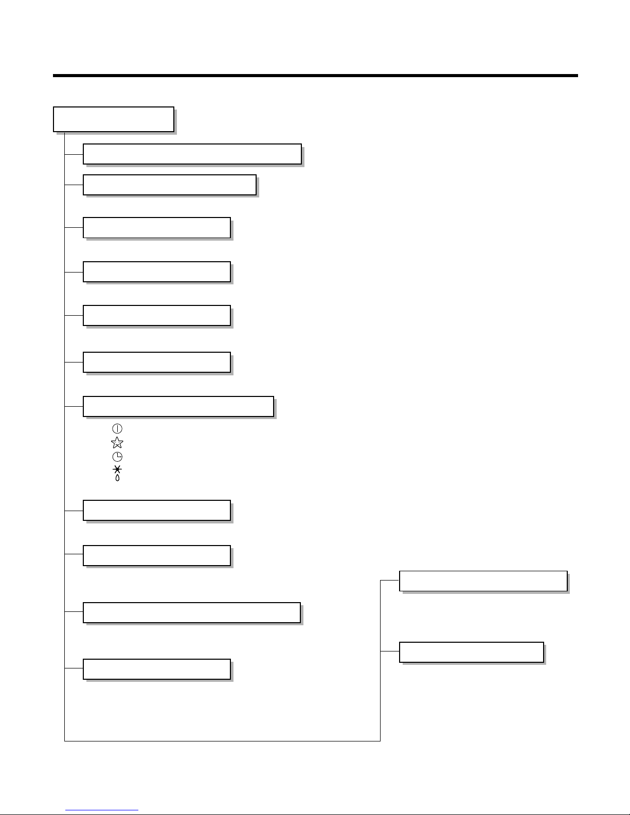
Contents
Functions
.................................................................................................................................
3
Product Specifications
..........................................................................................................
5
Dimensions
............................................................................................................................
12
Refrigeration Cycle Diagram
................................................................................................
14
Pipe Length and the Elevation.............................................................................................16
Wiring Diagram
......................................................................................................................
17
Operation Details
..................................................................................................................
21
Display Function
...................................................................................................................
29
Self-diagnosis Function
........................................................................................................
29
Installation
.............................................................................................................................
30
Operation
...............................................................................................................................
43
Disassembly of the parts (Indoor Unit)
...............................................................................
45
2-way, 3-way Valve
.................................................................................................................
51
Cycle Troubleshooting Guide
...............................................................................................
58
Electronic Parts Troubleshooting Guide
.............................................................................
59
Electronic Control Device
.....................................................................................................
65
Schematic Diagram
...............................................................................................................
67
Exploded View & Replacement Parts List
...........................................................................
69
- 3 -
Functions
• Room temperature sensor. (THERMISTOR)
• Maintains the room temperature in accordance with the Setting Temp.
• Indoor fan is delayed for 5 sec at the starting.
• Restarting is inhibited for approx. 3 minutes.
• High, Med, Low
--- Lights up in operation
--- Lights up in Sleep Mode
--- Lights up in Timer Mode
--- Lights up in Deice Mode (for Heating Model)
OUTDOOR --- Lights up in compressor operation (for Cooling Model)
• Intermittent operation of fan at low speed.
• The fan is switched to low(Cooling), med(Heating) speed.
• The unit will be stopped after 1, 2, 3, 4, 5, 6, 7 hours.
• The fan is switched to intermittent or irregular operation
•
The fan speed is automatically switched from high to low speed.
• The louver can be set at the desired position or swing
up and down automatically.
Indoor Unit
Operation ON/OFF by Remote controller
Sensing the Room Temperature
Room temperature control
Starting Current Control
Time Delay Safety Control
Indoor Fan Speed Control
Operation indication Lamps (LED)
Soft Dry Operation Mode
• Both the indoor and outdoor fan
stops during deicing.
• The indoor fan stops until the
evaporator piping temperature will be
reached at 28°C.
Sleep Mode Auto Control
Natural Air Control by CHAOS Logic
Airflow Direction Control
Deice (defrost) control (Heating)
Hot-start Control (Heating)
- 4 -
Healthy Dehumidification Operation Mode.
( )
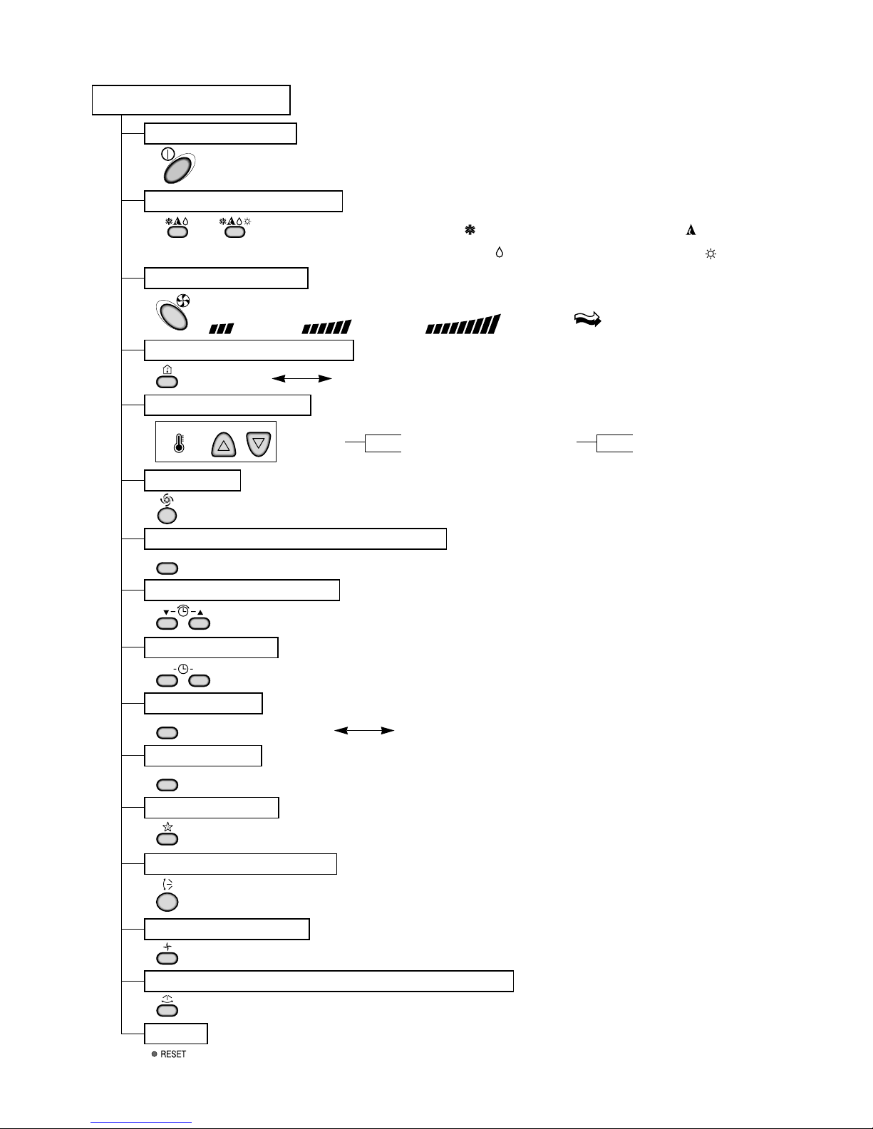
Remote Controller
Operation ON/OFF
Reset
Operation Mode Selection
Temperature Setting
Timer Selection
Timer Setting
JET COOL
Timer Cancel
Sleep Operation
Airflow Direction Control
(Cooling
model only)
(Heating
model only)
TEMPERATURE
LOW HIGH
Cooling Operation Mode.( )
Heating Operation Mode.( )
Auto Operation Mode.( )
Fan Operation Mode
Horizontal Airflow Direction Control Button(Option)
Room, Temperature Display
Setting the Time or Timer
PLASMA(Option)/NEGATIVE ION(Option)
ON OFF
SET
PLASMA
CANCEL
Fan Speed Selection
(Low) (Med) (High) (CHAOS)
: (High:39°C Low:11°C)
: OFF, ON, OFF ON
: Cancel Sleep Mode, Timer ON or Timer OFF
: 1, 2, 3, 4, 5, 6, 7, Off Timer
: Fan Operates without cooling or heating.
Cooling
Down to 18°C
Up to 30°C
Heating
Down to 16°C
Up to 30°C
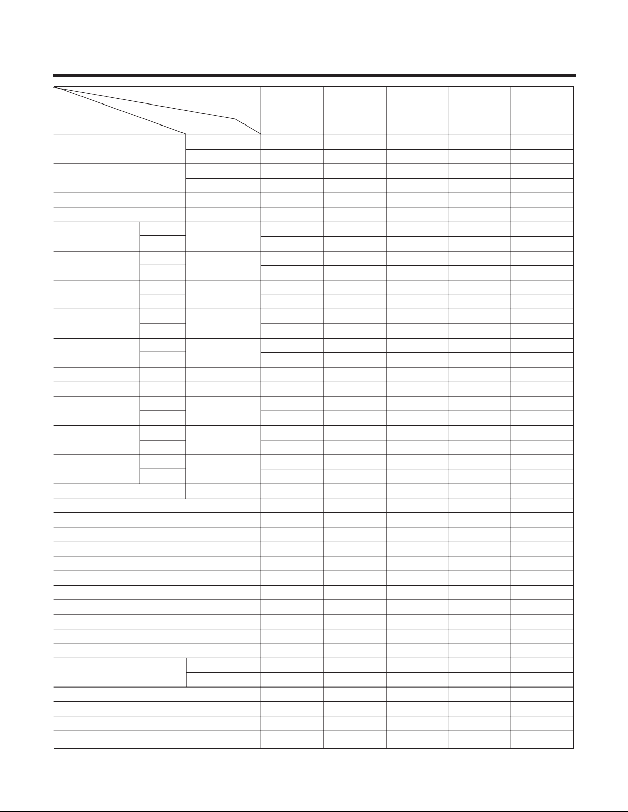
- 5 -
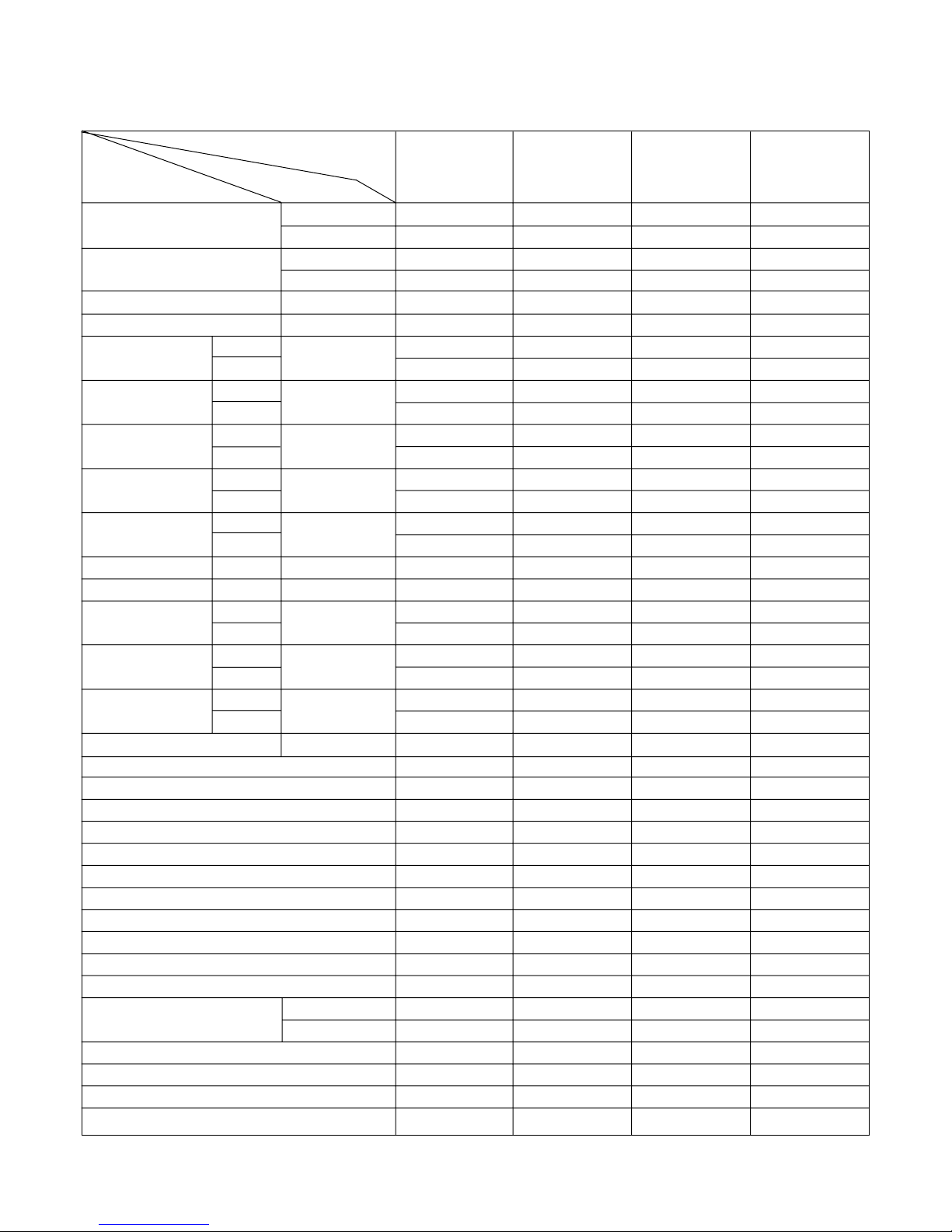
Product Specifications
Cooling Capacity
BTU/h(kcal/h)
W
Heating Capacity
BTU/h(kcal/h)
W
Moisture Removal l/h
Power Source Ø, V, Hz
Air Circulation m3/min
Noise Level dB(A)±3
Input W
Runnig Current
A
Starting Current
A
E.E.R. BTU/h-W
C.O.P W/W
Motor Output W
mm
Net. Weight kg
Refrigerant(R-22) g
Airflow Direction Control (Up & Down)
Airflow Direction Control (Right & Left)
Negative lon
Air Purifying Filter
Deicer
Hot Start
Chaos Wind
Micom Dry
Timer
Self Diagnosis
Remocon type
Service valve
Sleeping Operation
Drain Hose
Connecting Cable
Power Cord
18,000(4,536)
5,274
-
-
2.5
1Ø, 220-240V, 50Hz
12
42
39
53
1,900
-
8.8
-
52
-
9.5
-
20
62
1,080 x 314 x 181
870 x 655 x 320
12
57
820
YES
NO
NO
NO(OPTION)
NO
NO
YES
YES
24hr ON/OFF
YES
L.C.D Wireless
1/4"(6.35)
1/2"(12.7)
YES
YES
1.5mm
2
1.5mm
2
18,000(4,536)
5,274
19,000(4,788)
5,564
2.5
1Ø, 220-240V, 50Hz
12
42
39
53
1,950
1,950
8.7
8.7
53
53
9.2
2.86
20
62
1,080 x 314 x 181
870 x 655 x 320
12
59
1,270
YES
NO
NO
NO(OPTION)
YES
YES
YES
YES
24hr ON/OFF
YES
L.C.D Wireless
1/4"(6.35)
1/2"(12.7)
YES
YES
1.5, 0.75mm
2
1.5mm
2
18,000(4,536)
5,274
-
-
2.5
1Ø, 220V, 60Hz
14
42
40
51
1,900
-
8.9
-
52
-
9.47
-
21
60
1,080 x 314 x 181
870 x 655 x 320
12
57
870
YES
NO
NO
NO
NO
NO
YES
YES
24hr ON/OFF
YES
L.C.D Wireless
1/4"(6.35)
5/8"(15.88)
YES
YES
1.5mm
2
1.5mm
2
18,000(4,536)
5,274
19,000(4,788)
5,564
2.5
1Ø, 220V, 60Hz
14
42
40
51
1,800
1,900
8.5
8.9
52
52
10.0
2.93
21
60
1,080 x 314 x 181
870 x 655 x 320
12
58
1,360
YES
NO
NO
NO
YES
YES
YES
YES
24hr ON/OFF
YES
L.C.D Wireless
1/4"(6.35)
5/8"(15.88)
YES
YES
1.5, 0.75mm
2
1.5mm
2
18,000(4,536)
5,274
-
-
2.5
1Ø, 220~240V, 50Hz
12
42
39
53
1,610
-
7.0
-
52
-
9.5
-
20
62
1,080 x 314 x 181
870 x 655 x 320
12
57
800
YES
NO
NO
NO
NO
NO
YES
YES
24hr ON/OFF
YES
L.C.D Wireless
1/2"(12.7)
5/8"(15.88)
YES
YES
1.5mm
2
1.5mm
2
Model Name
Unit
Indoor
Outdoor
Indoor
Outdoor
Cooling
Heating
Cooling
Heating
Cooling
Heating
Cooling
Heating
Indoor
Outdoor
Indoor
Outdoor
Indoor
Outdoor
Liquid
Gas
Dimensions
(W x H x D)
Item
LS-
K1860CL/CM/CN
LS-
K1860HL/HM/HN
LS-
K1820CL/CM/CN
LS-
K1820HL/HM/HN
LS-K1863DL
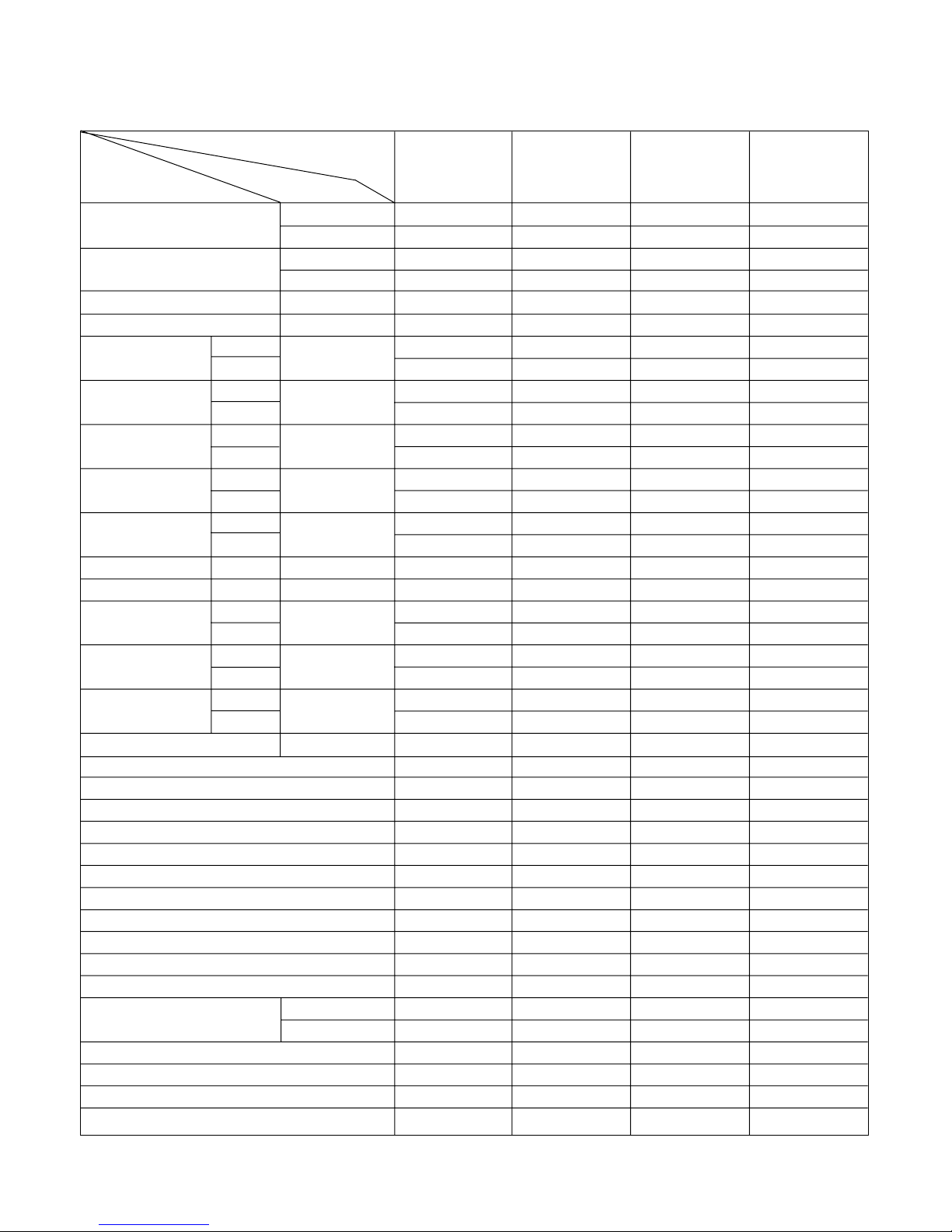
- 6 -
Cooling Capacity
BTU/h(kcal/h)
W
Heating Capacity
BTU/h(kcal/h)
W
Moisture Removal l/h
Power Source Ø, V, Hz
Air Circulation m3/min
Noise Level dB(A)±3
Input W
Runnig Current
A
Starting Current
A
E.E.R. BTU/h-W
C.O.P W/W
Motor Output W
mm
Net. Weight kg
Refrigerant(R-22) g
Airflow Direction Control (Up & Down)
Airflow Direction Control (Right & Left)
Negative lon
Air Purifying Filter
Plasma Filter
Deicer
Hot Start
Chaos Wind
Micom Dry
Timer
Self Diagnosis
Remocon type
Service valve
Sleeping Operation
Drain Hose
Connecting Cable
Power Cord
18,000(4,536)
5,274
-
-
2.5
1Ø, 220-240V, 50Hz
12
42
39
53
1,900
-
8.8
-
52
-
9.5
20
62
1,080 x 314 x 181
870 x 655 x 320
12
57
820
YES
YES
YES
YES
NO
NO
NO
YES
YES
24hr ON/OFF
YES
L.C.D Wireless
1/4"(6.35)
1/2"(12.7)
YES
YES
1.5mm
2
1.5mm
2
18,000(4,536)
5,274
19,000(4,788)
5,564
2.5
1Ø, 220-240V, 50Hz
12
42
39
53
1,950
1,950
8.7
8.7
53
53
9.2
2.86
20
62
1,080 x 314 x 181
870 x 655 x 320
12
59
1,270
YES
YES
YES
YES
NO
YES
YES
YES
YES
24hr ON/OFF
YES
L.C.D Wireless
1/4"(6.35)
1/2"(12.7)
YES
YES
1.5, 0.75mm
2
1.5mm
2
18,000(4,536)
5,274
19,000(4,788)
5,564
2.5
1Ø, 220-240V, 50Hz
12
42
39
53
1,950
1,950
9.2
9.2
53
53
9.2
2.86
20
62
1,080 x 314 x 181
870 x 655 x 320
12
59
1,470
YES
NO
NO
NO(OPTION)
NO
YES
YES
YES
YES
24hr ON/OFF
YES
L.C.D Wireless
1/4"(6.35)
1/2"(12.7)
YES
YES
1.5, 0.75mm
2
1.5mm
2
18,000(4,536)
5,274
19,000(4,788)
5,564
2.5
1Ø, 220-240V, 50Hz
12
42
39
53
1,950
1,950
9.2
9.2
53
53
9.2
2.86
20
62
1,080 x 314 x 181
870 x 655 x 320
12
59
1,470
YES
NO
NO
NO(OPTION)
YES
YES
YES
YES
YES
24hr ON/OFF
YES
L.C.D Wireless
1/4"(6.35)
1/2"(12.7)
YES
YES
1.5, 0.75mm
2
1.5mm
2
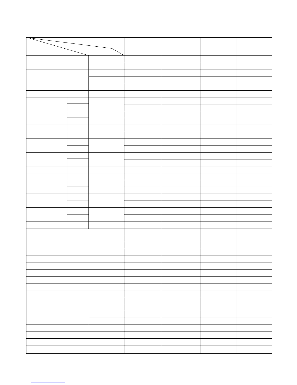
Model Name
Unit
Indoor
Outdoor
Indoor
Outdoor
Cooling
Heating
Cooling
Heating
Cooling
Heating
Cooling
Heating
Indoor
Outdoor
Indoor
Outdoor
Indoor
Outdoor
Liquid
Gas
Dimensions
(W x H x D)
Item
LS-
K1861CL/CM/CN
LS-
K1865HL/HM/HN
LS-
K1866HL/HM/HN
LS-
K1861HL/HM/HN
- 7 -
Cooling Capacity
BTU/h(kcal/h)
W
Heating Capacity
BTU/h(kcal/h)
W
Moisture Removal l/h
Power Source Ø, V, Hz
Air Circulation m3/min
Noise Level dB(A)
Input W
Runnig Current
A
Starting Current
A
E.E.R. BTU/h-W
C.O.P W/W
Motor Output W
mm
Net. Weight kg
Refrigerant(R-22) g
Airflow Direction Control (Up & Down)
Airflow Direction Control (Right & Left)
Negative lon
Air Purifying Filter
Deicer
Hot Start
Chaos Wind
Micom Dry
Timer
Self Diagnosis
Remocon type
Service valve
Sleeping Operation
Drain Hose
Connecting Cable
Power Cord
24,000(6,048)
7,032
-
-
2.5
1Ø, 220-240V, 50Hz
16
42
44
54
2,470
-
11.3
-
52
-
9.7
35
83
1,080 x 314x 181
870 x 655 x 320
12
57
1,520
YES
NO
NO
NO(OPTION)
NO
NO
YES
YES
24hr ON/OFF
YES
L.C.D Wireless
3/8"(9.52)
5/8"(15.88)
YES
YES
2.5mm
2
2.5mm
2
24,000(6,048)
7,032
24,000(6,040)
7,032
2.5
1Ø, 220-240V, 50Hz
16
42
44
54
2,670
2,610
12.2
11.9
53
53
9.0
2.635
35
83
1,080 x 314 x 181
870 x 655 x 320
12
59
1,300
YES
NO
NO
NO(OPTION)
YES
YES
YES
YES
24hr ON/OFF
YES
L.C.D Wireless
3/8"(9.52)
5/8"(15.88)
YES
YES
2.5, 0.75mm
2
2.5mm
2
24,000(6,048)
7,032
-
-
3.5
1Ø, 220V, 60Hz
15.5
48
42±3
54±3
2,100
-
9.8
-
61
-
10.5
35
78
1,080 x 314 x 181
870 x 655 x 320
12
58
1,580
YES
NO
NO
NO(OPTION)
NO
NO
YES
YES
24hr ON/OFF
YES
L.C.D Wireless
1/4"(6.35)
5/8"(15.88)
YES
YES
2.5mm
2
2.5mm
2
24,000(6,048)
7,032
24,000(6,048)
7,032
3.5
1Ø, 220V, 60Hz
16
48
44±3
55±3
2,525
2,525
12.0
12.0
70
70
9.5
2.78
35
78
1,080 x 314 x 181
870 x 655 x 320
12
65
1,610
YES
NO
NO
NO(OPTION)
YES
YES
YES
YES
24hr ON/OFF
YES
L.C.D Wireless
1/4"(6.35)
5/8"(15.88)
YES
YES
2.5, 0.75mm
2
2.5mm
2
Model Name
Unit
Indoor
Outdoor
Indoor
Outdoor
Cooling
Heating
Cooling
Heating
Cooling
Heating
Cooling
Heating
Indoor
Outdoor
Indoor
Outdoor
Indoor
Outdoor
Liquid
Gas
Dimensions
(W x H x D)
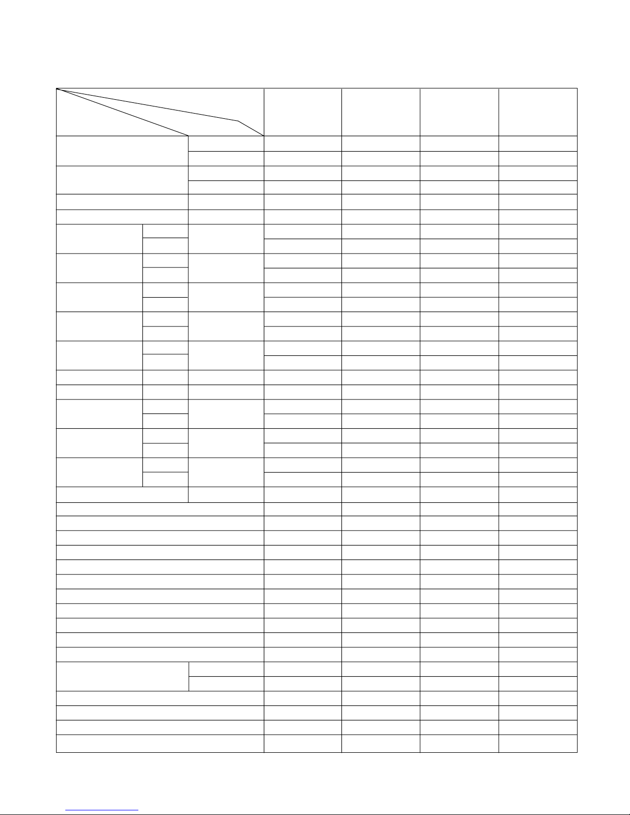
Item
LS-
K2460CL/CM/CN
LS-
K2460HL/HM/HN
LS-
K2420CL/CM/CN
LS-
K2420HL/HM/HN
- 8 -
Cooling Capacity
BTU/h(kcal/h)
W
Heating Capacity
BTU/h(kcal/h)
W
Moisture Removal l/h
Power Source Ø, V, Hz
Air Circulation m3/min
Noise Level dB(A)
Input W
Runnig Current
A
Starting Current
A
E.E.R. BTU/h-W
C.O.P W/W
Motor Output W
mm
Net. Weight kg
Refrigerant(R-22) g
Airflow Direction Control (Up & Down)
Airflow Direction Control (Right & Left)
Negative lon
Air Purifying Filter
Deicer
Hot Start
Chaos Wind
Micom Dry
Timer
Self Diagnosis
Remocon type
Service valve
Sleeping Operation
Drain Hose
Connecting Cable
Power Cord
26,000
7,032
-
-
2.5
1Ø, 220-240V, 50Hz
16
42
44
54
2,470
-
11.3
-
52
-
9.7
35
83
1,080 x 314 x 181
870 x 655 x 320
12
57
1,520
YES
YES
YES
YES
NO
NO
YES
YES
24hr ON/OFF
YES
L.C.D Wireless
3/8"(9.52)
5/8"(15.88)
YES
YES
2.5mm
2
2.5mm
2
26,000
7,032
24,000(6,040)
7,032
2.5
1Ø, 220-240V, 50Hz
16
42
44
54
2,670
2,610
12.2
11.9
53
53
9.0
2.635
35
83
1,080 x 314 x 181
870 x 655 x 320
12
59
1,300
YES
YES
YES
YES
YES
YES
YES
YES
24hr ON/OFF
YES
L.C.D Wireless
3/8"(9.52)
5/8"(15.88)
YES
YES
2.5, 0.75mm
2
2.5mm
2
26,000
7,032
-
-
3.5
1Ø, 220V, 60Hz
15.5
48
42±3
54±3
2,100
-
9.8
-
61
-
10.5
35
78
1,080 x 314 x 181
870 x 655 x 320
12
58
1,580
YES
YES
YES
YES
NO
NO
YES
YES
24hr ON/OFF
YES
L.C.D Wireless
1/4"(6.35)
5/8"(15.88)
YES
YES
2.5mm
2
2.5mm
2
26,000
7,032
24,000(6,048)
7,032
3.5
1Ø, 220V, 60Hz
16
48
44±3
55±3
2,525
2,525
12.0
12.0
70
70
9.5
2.78
35
78
1,080 x 314 x 181
870 x 655 x 320
12
65
1,610
YES
YES
YES
YES
YES
YES
YES
YES
24hr ON/OFF
YES
L.C.D Wireless
1/4"(6.35)
5/8"(15.88)
YES
YES
2.5, 0.75mm
2
2.5mm
2
Model Name
Unit
Indoor
Outdoor
Indoor
Outdoor
Cooling
Heating
Cooling
Heating
Cooling
Heating
Cooling
Heating
Indoor
Outdoor
Indoor
Outdoor
Indoor
Outdoor
Liquid
Gas
Dimensions
(W x H x D)
Item
LS-
K2661CL/CM/CN
LS-
K2661HL/HM/HN
LS-
K2621CL/CM/CN
LS-
K2621HL/HM/HN

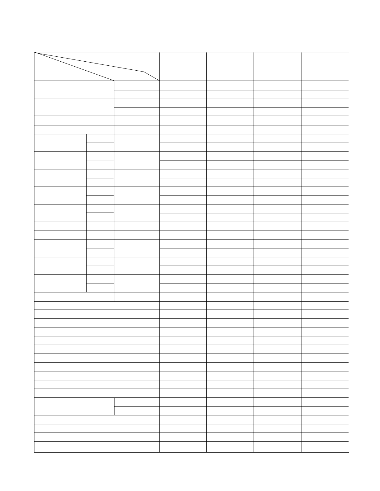
- 9 -
Cooling Capacity BTU/h(kcal/h)
W
Heating Capacity BTU/h(kcal/h)
W
Moisture Removal l/h
Power Source Ø, V, Hz
Air Circulation m
3
/min
Noise Level dB(A)
±3
Input W
Runnig Current
A
Starting Current
A
E.E.R. BTU/h-W
C.O.P W/W
Motor Output W
mm
Net. Weight kg
Refrigerant(R-22) g
Airflow Direction Control (Up & Down)
Airflow Direction Control (Right & Left)
Negative lon
Air Purifying Filter
Plasma Filter
Soft Start
Deicer
Hot Start
Chaos Wind
Micom Dry
Timer
Self Diagnosis
Remocon type
Service valve
Sleeping Operation
Drain Hose
Connecting Cable
Power Cord
18,000(4,536)
5,274
-
-
2.5
1Ø, 220-240V, 50Hz
12
42
39
53
1,900
-
8.8
-
52
-
9.5
20
62
1,080 x 314 x 181
870 x 655 x 320
12
57
820
YES
NO
NO
YES
YES
NO
NO
NO
YES
YES
24hr ON/OFF
YES
L.C.D Wireless
1/4"(6.35)
1/2"(12.7)
YES
YES
1.5mm
2
1.5mm
2
18,000(4,536)
5,274
19,000(4,788)
5,564
2.5
1Ø, 220-240V, 50Hz
12
42
39
53
1,950
1,950
8.7
8.7
53
53
9.2
2.86
20
62
1,080 x 314 x 181
870 x 655 x 320
12
59
1,270
YES
NO
NO
YES
YES
NO
YES
YES
YES
YES
24hr ON/OFF
YES
L.C.D Wireless
1/4"(6.35)
1/2"(12.7)
YES
YES
1.5, 0.75mm
2
1.5mm
2
24,000(6,048)
7,032
-
-
2.5
1Ø, 220-240V, 50Hz
16
42
44
54
2,470
-
11.3
-
52
-
9.7
35
83
1,080 x 314 x 181
870 x 655 x 320
12
57
1,520
YES
NO
NO
YES
YES
NO
NO
NO
YES
YES
24hr ON/OFF
YES
L.C.D Wireless
3/8"(9.52)
5/8"(15.88)
YES
YES
2.5mm
2
2.5mm
2
24,000(6,048)
7,032
24,000(6,048)
7,032
2.5
1Ø, 220-240V, 50Hz
16
42
44
54
2,670
2,610
12.2
11.9
53
53
9.0
2.635
35
83
1,080 x 314 x 181
870 x 655 x 320
12
59
1,550
YES
NO
NO
YES
YES
NO
YES
YES
YES
YES
24hr ON/OFF
YES
L.C.D Wireless
3/8"(9.52)
5/8"(15.88)
YES
YES
2.5, 0.75mm
2
2.5mm
2
Model Name
Unit
Indoor
Outdoor
Indoor
Outdoor
Cooling
Heating
Cooling
Heating
Cooling
Heating
Cooling
Heating
Indoor
Outdoor
Indoor
Outdoor
Indoor
Outdoor
Liquid
Gas
Dimensions
(W x H x D)
Item
LS-
K1862CL/CM/CN
LS-
K1862HL/HM/HN
LS-
K2462CL/CM/CN
LS-
K2462HL/HM/CN
- 10 -
Cooling Capacity
BTU/h(kcal/h)
W
Heating Capacity
BTU/h(kcal/h)
W
Moisture Removal l/h
Power Source Ø, V, Hz
Air Circulation m3/min
Noise Level dB(A)
Input W
Runnig Current
A
Starting Current
A
E.E.R. BTU/h-W
C.O.P W/W
Motor Output W
mm
Net. Weight kg
Refrigerant(R-22) g
Airflow Direction Control (Up & Down)
Airflow Direction Control (Right & Left)
Negative lon
Air Purifying Filter
Deicer
Hot Start
Chaos Wind
Micom Dry
Timer
Self Diagnosis
Remocon type
Service valve
Sleeping Operation
Drain Hose
Connecting Cable
Power Cord
24,000(6,048)
7,032
-
-
3.5
1Ø, 220V, 60Hz
15.5
48
42±3
54±3
2,100
-
9.8
-
61
-
10.5
35
78
1,080 x 314 x 181
870 x 655 x 320
12
58
1,580
YES
NO
NO
YES
NO
NO
YES
YES
24hr ON/OFF
YES
L.C.D Wireless
1/4"(6.35)
5/8"(15.88)
YES
YES
2.5mm
2
2.5mm
2
24,000(6,048)
7,032
24,000(6,048)
7,032
3.5
1Ø, 220V, 60Hz
16
48
44±3
55±3
2,525
2,525
12.0
12.0
70
70
9.5
2.78
35
78
1,080 x 314 x 181
870 x 655 x 320
12
65
1,610
YES
NO
NO
YES
YES
YES
YES
YES
24hr ON/OFF
YES
L.C.D Wireless
1/4"(6.35)
5/8"(15.88)
YES
YES
2.5, 0.75mm
2
2.5mm
2
18,000(4,536)
5,274
-
-
2.5
1Ø, 220V, 60Hz
14
42
40
51
1,900
-
8.9
-
52
-
9.47
21
60
1,080 x 314 x 181
870 x 655 x 320
12
57
870
YES
NO
NO
YES
NO
NO
YES
YES
24hr ON/OFF
YES
L.C.D Wireless
1/4"(6.35)
5/8"(15.88)
YES
YES
1.5mm
2
1.5mm
2
18,000(4,536)
5,274
19,000(4,788)
5,564
2.5
1Ø, 220V, 60Hz
14
42
40
51
1,800
1,900
8.5
8.9
52
52
10.0
2.93
21
60
1,080 x 314 x 181
870 x 655 x 320
12
58
1,360
YES
NO
NO
YES
YES
YES
YES
YES
24hr ON/OFF
YES
L.C.D Wireless
1/4"(6.35)
5/8"(15.88)
YES
YES
1.5, 0.75mm
2
1.5mm
2
Model Name
Unit
Indoor
Outdoor
Indoor
Outdoor
Cooling
Heating
Cooling
Heating
Cooling
Heating
Cooling
Heating
Indoor
Outdoor
Indoor
Outdoor
Indoor
Outdoor
Liquid
Gas
Dimensions
(W x H x D)
Item
LS-
K2422CL/CM/CN
LS-
K2422HL/HM/HN
LS-
K1822CL/CM/CN
LS-
K1822HL/HM/HN
- 11 -
Cooling Capacity
BTU/h(kcal/h)
W
Heating Capacity
BTU/h(kcal/h)
W
Moisture Removal l/h
Power Source Ø, V, Hz
Air Circulation m3/min
Noise Level dB(A)
Input W
Runnig Current
A
Starting Current
A
E.E.R. BTU/h-W
C.O.P W/W
Motor Output W
mm
Net. Weight kg
Refrigerant(R-22) g
Airflow Direction Control (Up & Down)
Airflow Direction Control (Right & Left)
Negative lon
Air Purifying Filter
Deicer
Hot Start
Chaos Wind
Micom Dry
Timer
Self Diagnosis
Remocon type
Service valve
Sleeping Operation
Drain Hose
Connecting Cable
Power Cord
26,000
7,032
-
-
2.5
1Ø, 220-240V, 50Hz
16
42
44
54
2,470
-
11.3
-
52
-
9.7
35
83
1,080 x 314 x 181
870 x 655 x 320
12
57
1,520
YES
YES
YES
YES
NO
NO
YES
YES
24hr ON/OFF
YES
L.C.D Wireless
3/8"(9.52)
5/8"(15.88)
YES
YES
2.5mm
2
2.5mm
2
26,000
7,032
24,000(6,040)
7,032
2.5
1Ø, 220-240V, 50Hz
16
42
44
54
2,670
2,610
12.2
11.9
53
53
9.0
2.635
35
83
1,080 x 314 x 181
870 x 655 x 320
12
59
1,300
YES
YES
YES
YES
YES
YES
YES
YES
24hr ON/OFF
YES
L.C.D Wireless
3/8"(9.52)
5/8"(15.88)
YES
YES
2.5, 0.75mm
2
2.5mm
2
26,000
7,032
-
-
3.5
1Ø, 220V, 60Hz
15.5
48
42±3
54±3
2,100
-
9.8
-
61
-
10.5
35
78
1,080 x 314 x 181
870 x 655 x 320
12
58
1,580
YES
YES
YES
YES
NO
NO
YES
YES
24hr ON/OFF
YES
L.C.D Wireless
1/4"(6.35)
5/8"(15.88)
YES
YES
2.5mm
2
2.5mm
2
26,000
7,032
24,000(6,048)
7,032
3.5
1Ø, 220V, 60Hz
16
48
44±3
55±3
2,525
2,525
12.0
12.0
70
70
9.5
2.78
35
78
1,080 x 314 x 181
870 x 655 x 320
12
65
1,610
YES
YES
YES
YES
YES
YES
YES
YES
24hr ON/OFF
YES
L.C.D Wireless
1/4"(6.35)
5/8"(15.88)
YES
YES
2.5, 0.75mm
2
2.5mm
2
Model Name
Unit
Indoor
Outdoor
Indoor
Outdoor
Cooling
Heating
Cooling
Heating
Cooling
Heating
Cooling
Heating
Indoor
Outdoor
Indoor
Outdoor
Indoor
Outdoor
Liquid
Gas
Dimensions
(W x H x D)
Item
LS-
K2662CL/CM/CN
LS-
K2662HL/HM/HN
LS-
K2622CL/CM/CN
LS-
K2622HL/HM/HN
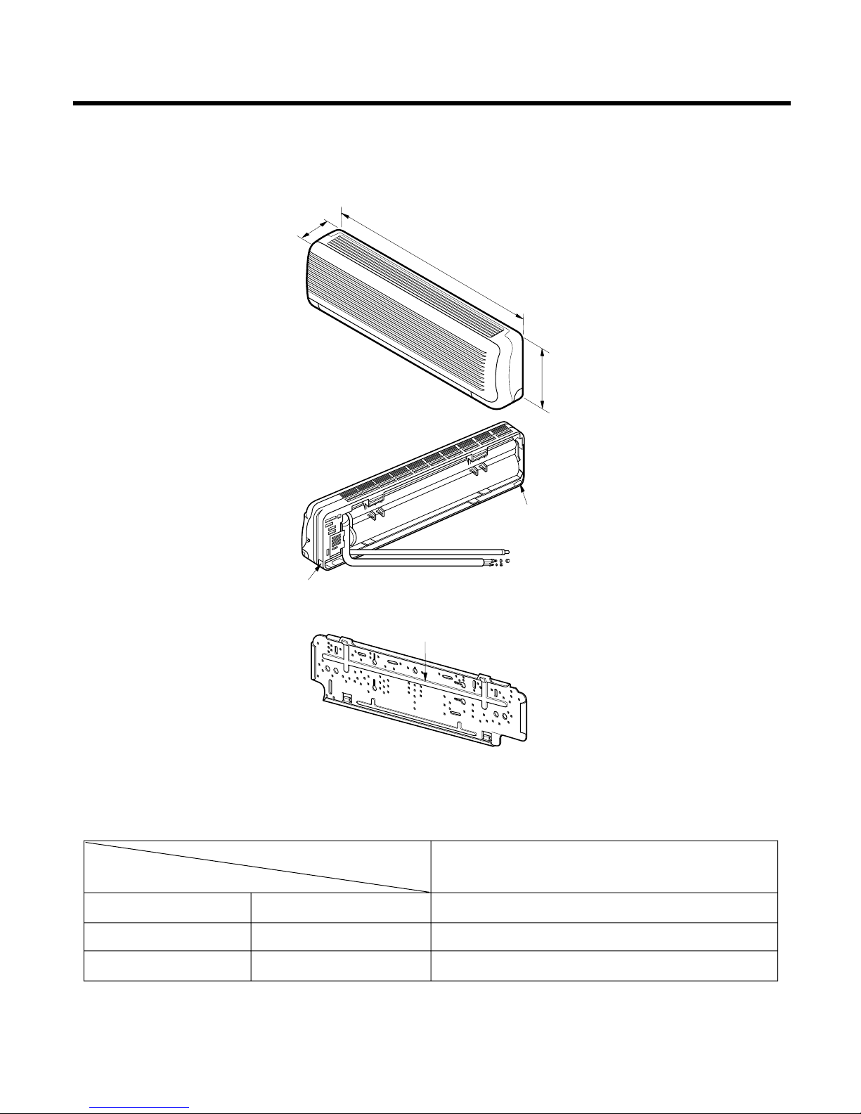
(1) Indoor Unit
- 12 -
Dimensions
Tubing hole cover
Tubing hole cover
Installation plate
D
W
H
W
H
Tubing hole cover
Tubing hole cover
Installation plate
D
MODEL
ALL MODELS
DIMENSION
W mm 1,080
H mm 314
D mm 181
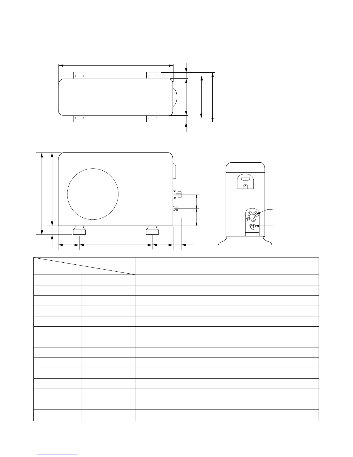
- 13 -
W
L7 L6 L8 L9
D
L1
L2
L3
L10L11
L4L5
H
Gas side
3-way valve
Liquid side
2-way valve
(2) Outdoor Unit
MODEL
DIM
W mm 870
H mm 655
D mm 320
L1 mm 370
L2 mm 340
L3 mm 25
L4 mm 630
L5 mm 25
L6 mm 546
L7 mm 162
L8 mm 162
L9 mm 54
L10 mm 74.5
L11 mm 79
ALL MODELS
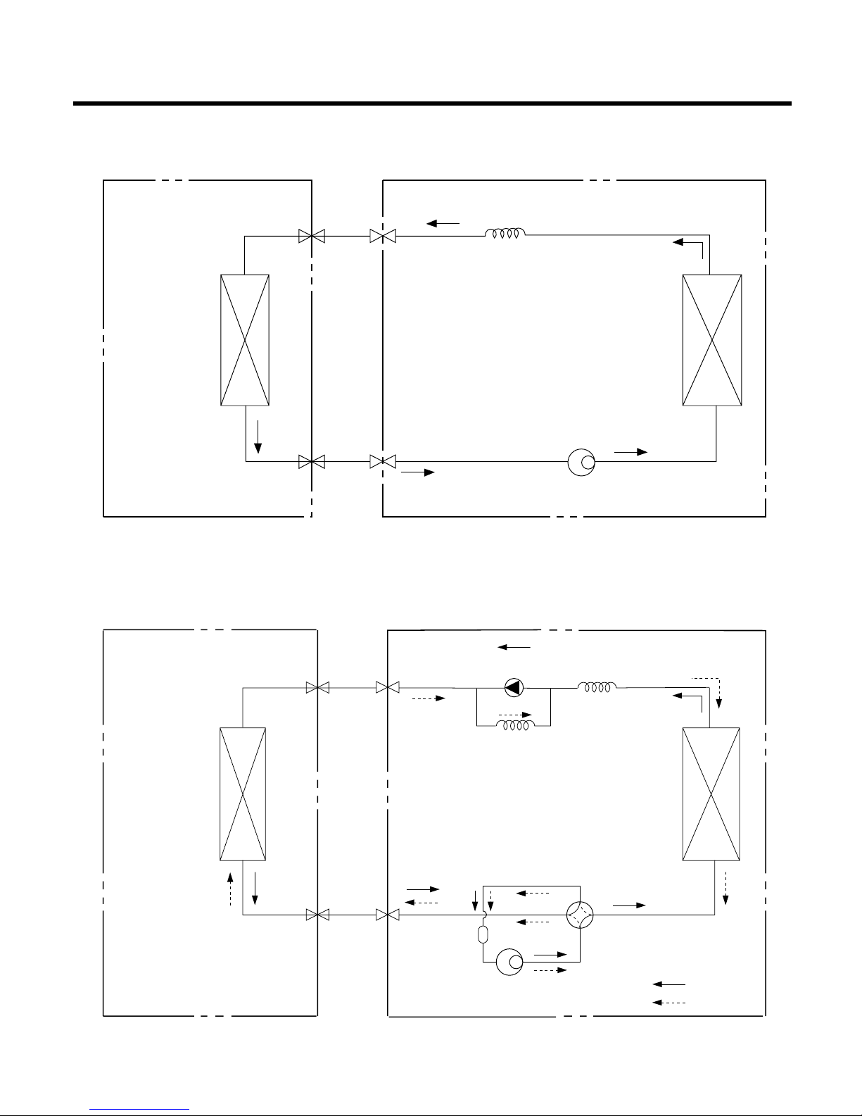
- 14 -
Refrigeration Cycle Diagram
INDOOR UNIT OUTDOOR UNIT
INDOOR UNIT OUTDOOR UNIT
HEAT
EXCHANGE
(EVAPORATOR)
HEAT
EXCHANGE
(EVAPORATOR)
HEAT
EXCHANGE
(CONDENSER)
HEAT
EXCHANGE
(CONDENSER)
COMPRESSOR
COMPRESSOR
ACCUMU
LATOR
GAS SIDE
GAS SIDE
3-WAY VALVE
LIQUID SIDE
LIQUID SIDE
2-WAY VALVE
CAPILLARY TUBE
CAPILLARY TUBE
CHECK VALVE
(Heating Model only)
COOLING
HEATING
REVERSING
VALVE
(Heating Model Only)
(1) Cooling Only Models
(2) Cooling & Heating Models
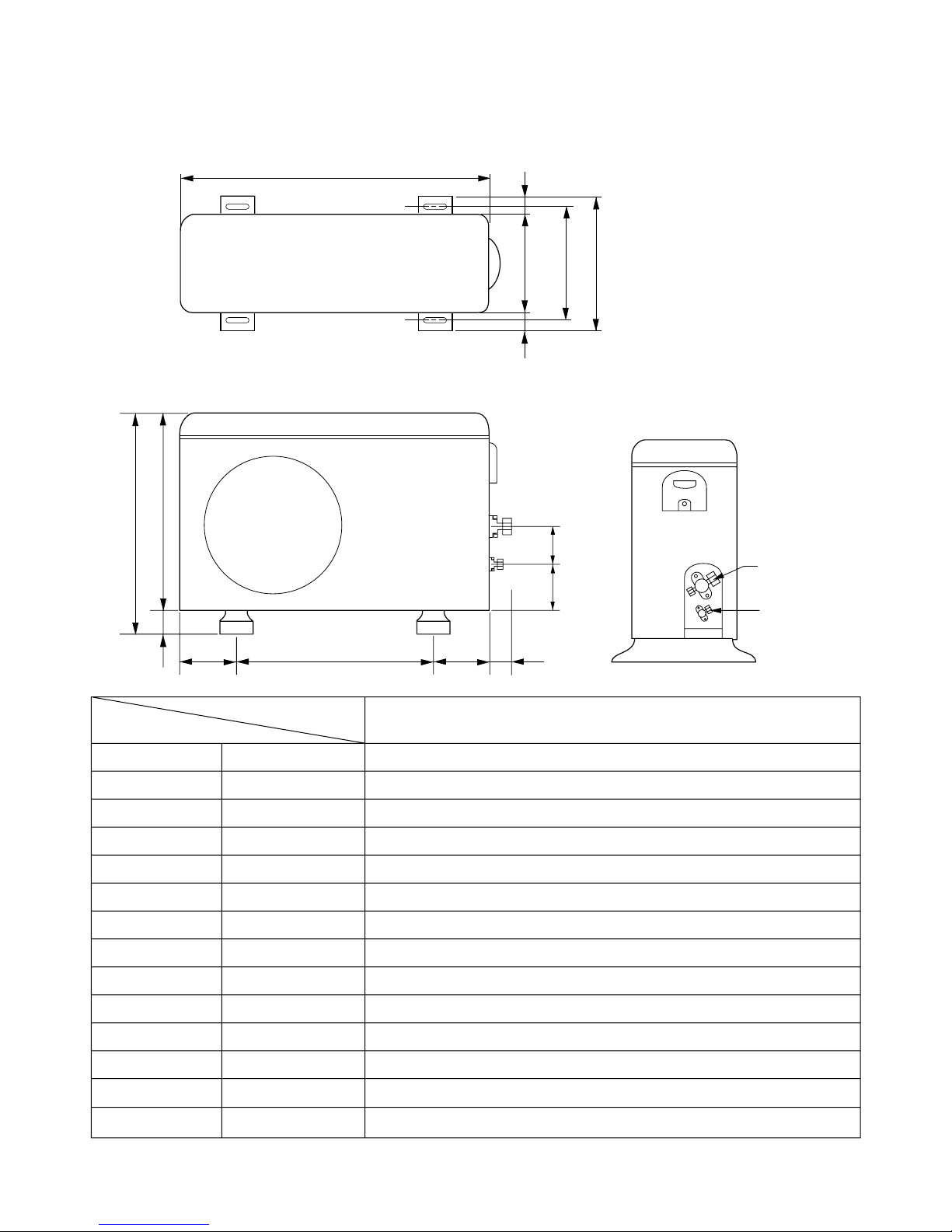
- 15 -
W
L7 L6 L8 L9
D
L1
L2
L3
L10L11
L4L5
H
Gas side
3-way valve
Liquid side
2-way valve
(2) Outdoor Unit
MODEL
DIM
W mm 870
H mm 655
D mm 320
L1 mm 370
L2 mm 340
L3 mm 25
L4 mm 630
L5 mm 25
L6 mm 546
L7 mm 162
L8 mm 162
L9 mm 54
L10 mm 74.5
L11 mm 79
ALL MODELS
- 16 -
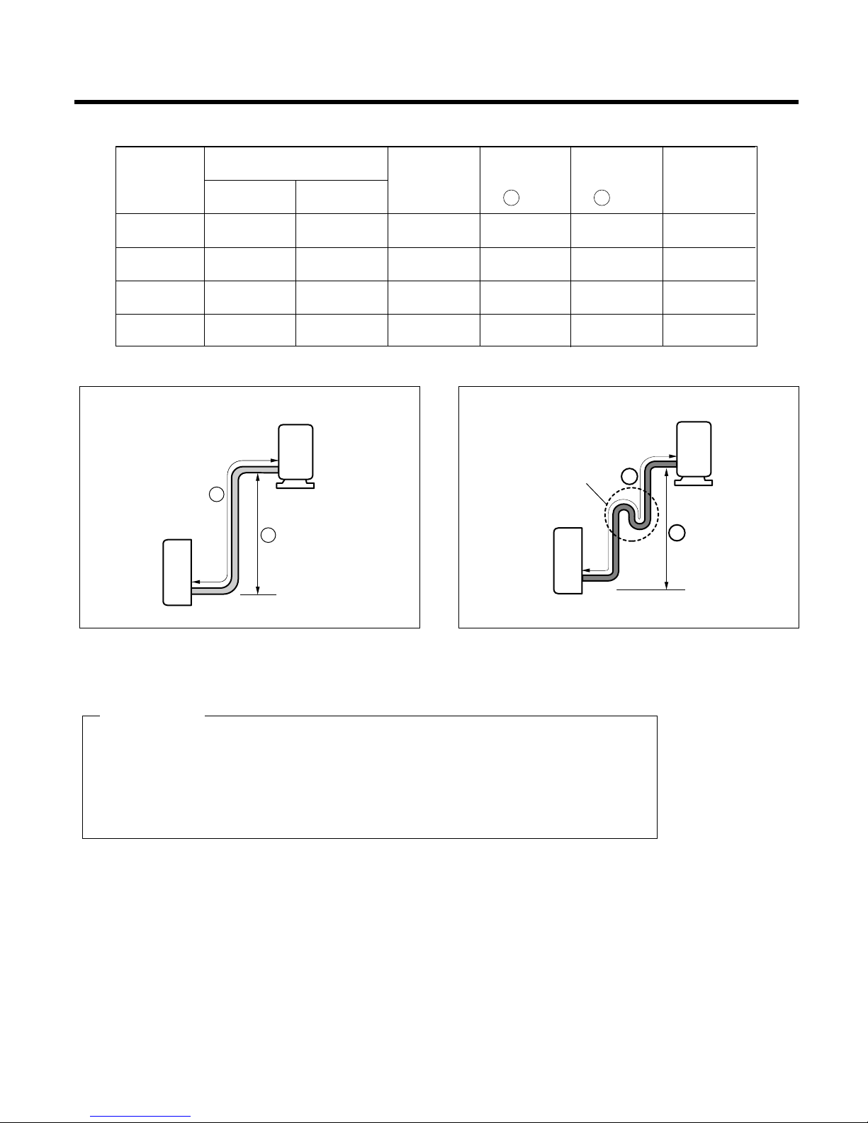
Pipe length and the elevation
* Capicity is based on standard length and maximum allowance length is the basis of
reliability.
* Oil trap should be installed per 5~7 meters.
* Numerical value in "( )" is for Rotary Comp. model.
CAUTION
Outdoor unit
Indoor unit
A
B
A
Oil trap
Outdoor unit
Indoor unit
B
In case more than 5m
18K(60Hz) 5/8" 1/4" 5 10 20 20
18K(50Hz) 1/2" 1/4" 5 15 30 30
24K(60Hz) 5/8" 1/4" 5 15 30 30
24K(50Hz) 5/8" 3/8" 5 15 30 30
Pipe Size
Capacity
(Btu/h)
GAS LIQUID
Additional
Refrigerant
(g/m)
Max.
Length
A (m)
Max.
Elevation
B (m)
Standard
Length
(m)
- 17 -
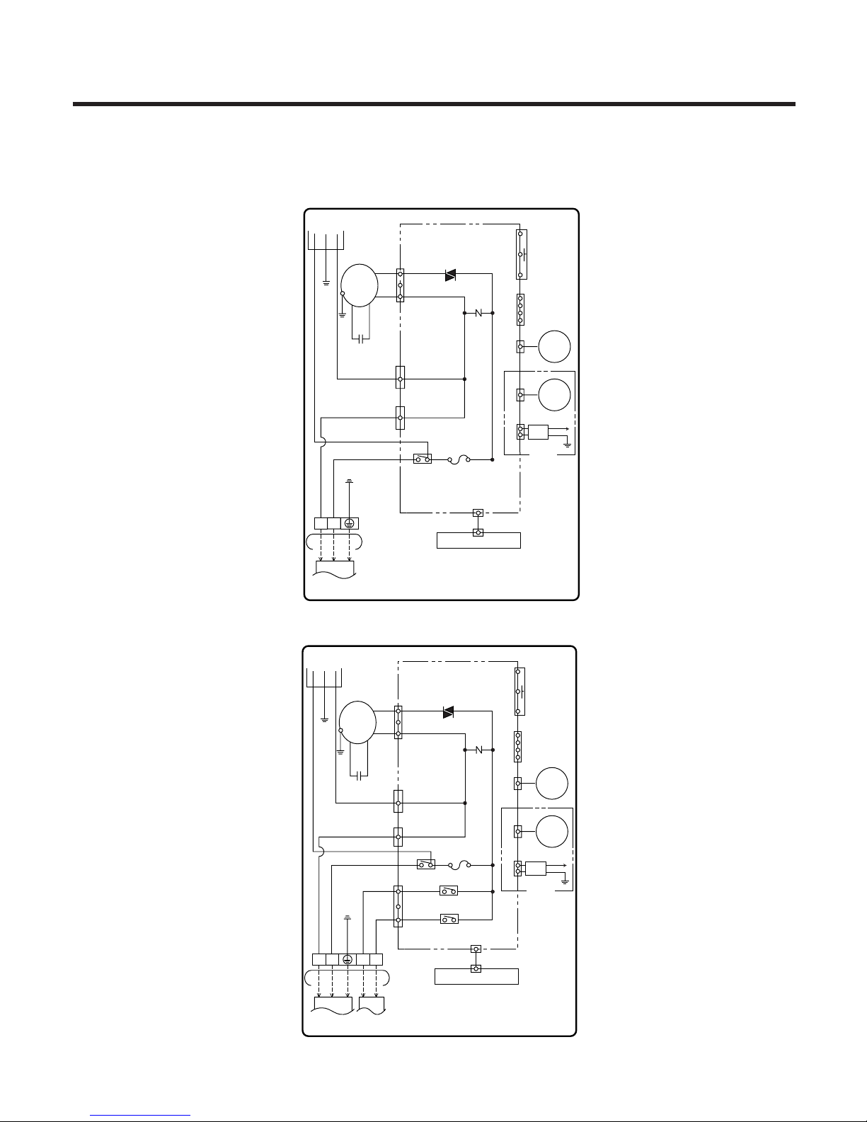
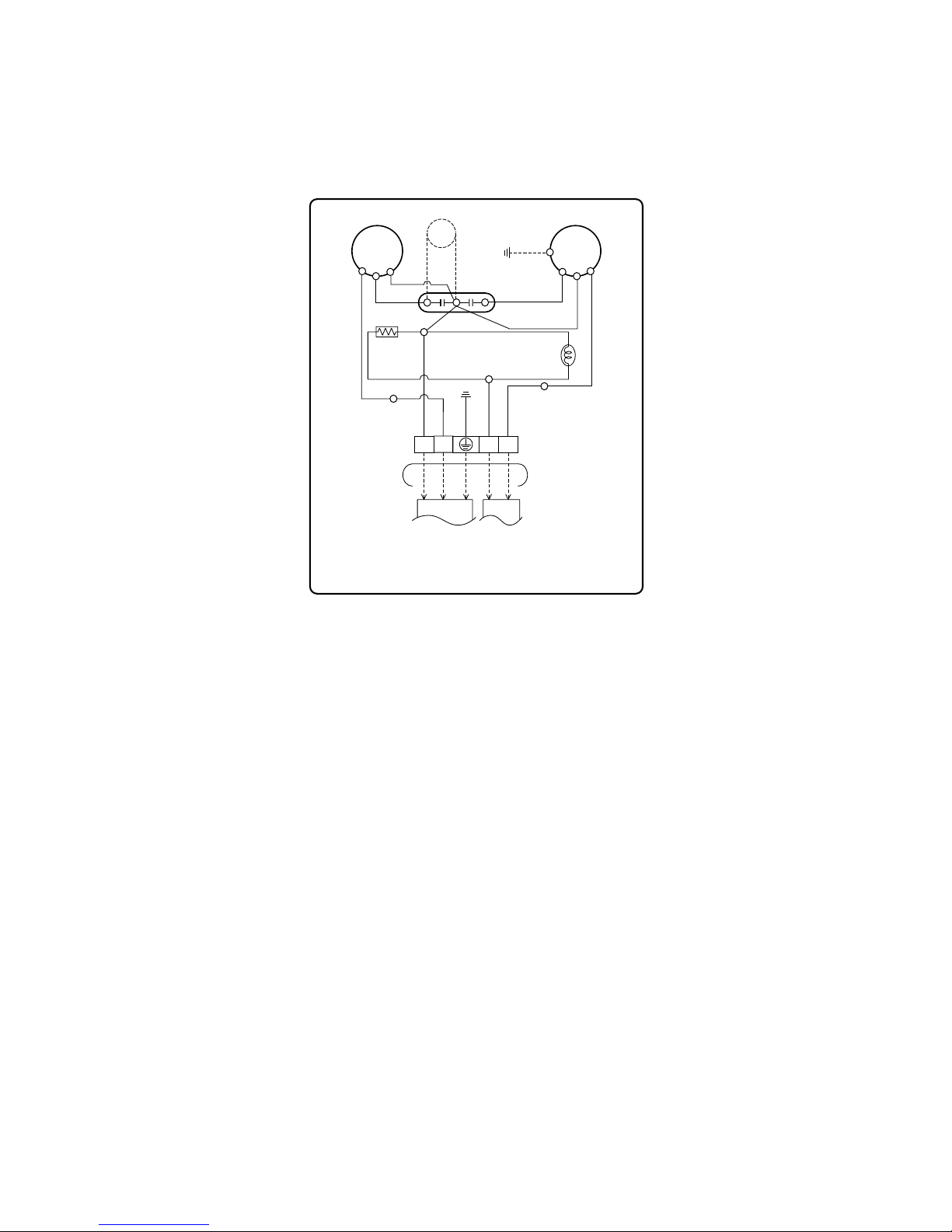
Wiring Diagram
(1) Indoor Unit
1. LS-K1820/1860/1861/2420/2460/2621/2661CL/CM/CN, LS-K1863DL
2. LS-K1820/1860/1861/1865/2420/2460/2621/2661HL/HM/HN
3854A90003L
INDOOR WIRING DIAGRAM
CN-DISP1
FUSE
AC250V/T2A
CN-TH1
SSR
SH-CAPA.
BR
GN/YL
BR
YL
OR
BK
CN-TAB1CN-TAB2
RY-COMP.
ZNR
CN-MOTOR
THERMISTOR
FORCED
OPERATION
AUTO
RESTART
REMOTE
CONTROL
MOTOR
MAIN PCB
ASM
DISPLAY PCB ASM
POWER
TO OUTDOOR UNIT
PILLAR
TERMINAL
BRBLGN/YL
BR
BL
GN/YL
1(L) 2(N
)
3
4
BL
CN-U/D
STEP
MOTOR
CN-L/R
STEP
MOTOR
WH
ION
H.V.B
GN
(GN/YL)
OPTION
3854A90003J
INDOOR WIRING DIAGRAM
CN-DISP1
CN-U/D
FUSE
AC250V/T2A
CN-TH1
SSR
SH-CAPA.
BR
GN/YL
BL
BR
YL
OR
BK
CN-TAB1CN-TAB2
CN-4WAY
RY-COMP.
ZNR
RY-4WAY
RY-FAN
CN-MOTOR
THERMISTOR
FORCED
OPERATION
AUTO
RESTART
REMOTE
CONTROL
STEP
MOTOR
CN-L/R
STEP
MOTOR
MOTOR
MAIN PCB
ASM
DISPLAY PCB ASM
POWER
TO OUTDOOR UNIT
PILLAR
TERMINAL
BR
BLRDBK
GN/YL
BR
BLRDBK
GN/YL
1(L) 2(N
)
3 4
4
3
WH
ION
H.V.B
GN
(GN/YL)
OPTION
- 18 -
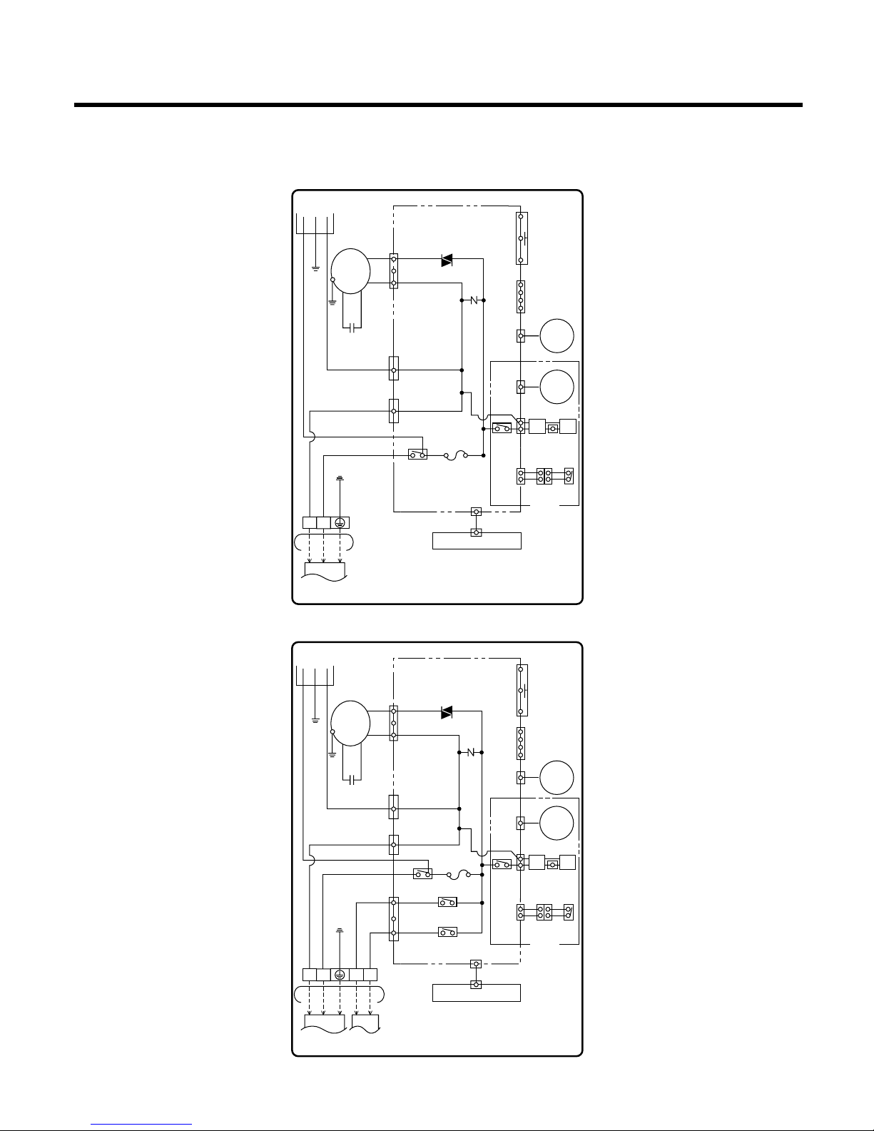
3. LS-K1822/1862/2422/2462/2662CL/CM/CN
4. LS-K1822/1862/1866/2422/2462/2662HL/HM/HN
3854A90003U
INDOOR WIRING DIAGRAM
CN-DISP1
FUSE
AC250V/T2A
CN-TH1
SSR
SH-CAPA.
BR
GN/YL
BR
YL
OR
BK
CN-TAB1CN-TAB2
RY-COMP.
ZNR
CN-MOTOR
THERMISTOR
FORCED
OPERATION
AUTO
RESTART
REMOTE
CONTROL
MOTOR
MAIN PCB
ASM
DISPLAY PCB ASM
POWER
TO OUTDOOR UNIT
PILLAR
TERMINAL
BRBLGN/YL
BR
BL
GN/YL
1(L) 2(N
)
3
4
BL
CN-U/D
STEP
MOTOR
CN-L/R
STEP
MOTOR
RD
H.V.B A/CL
OPTION
BK
BK BK
BK
BK BK
LIMIT
S/W
3854A90003V
INDOOR WIRING DIAGRAM
CN-DISP1
CN-U/D
FUSE
AC250V/T2A
CN-TH1
SSR
SH-CAPA.
BR
GN/YL
BL
BR
YL
OR
BK
CN-TAB1CN-TAB2
CN-4WAY
RY-COMP.
ZNR
RY-4WAY
RY-FAN
CN-MOTOR
THERMISTOR
FORCED
OPERATION
AUTO
RESTART
REMOTE
CONTROL
STEP
MOTOR
MOTOR
MAIN PCB
ASM
DISPLAY PCB ASM
POWER
TO OUTDOOR UNIT
PILLAR
TERMINAL
BR
BLRDBK
GN/YL
BR
BLRDBK
GN/YL
1(L) 2(N
)
3 4
4
3
CN-L/R
STEP
MOTOR
RD
H.V.B A/CL
OPTION
BK
BK BK
BK
BK BK
LIMIT
S/W
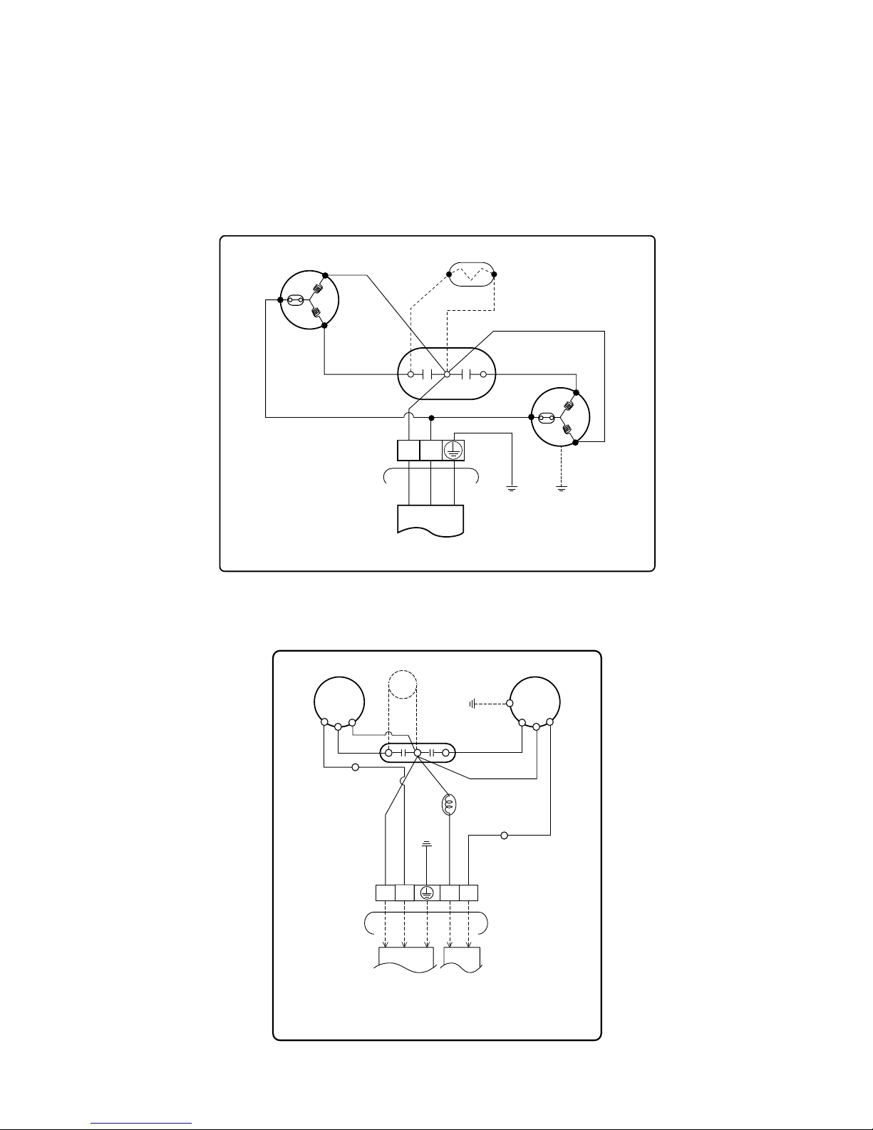
- 19 -
R
S
C
F
H
C
COMP.
TO INDOOR UNIT
OUTDOOR WIRING DIAGRAM
MOTOR
FAN
BR
OPTION
PTC
CAPACITOR
YL
TP
RD
TERMINAL
BLOCK
3854AR2735F
BR(OR)
BR BL
BK
YL
GN/YL
GN/YL
GN/YL
1(L) 2(N)
(2) Outdoor Unit
1. LS-K1820/1860/1861/1862/2420/2422/2460/2462/2621/2622/2661/2662CL/CM/CN/CN
LS-K1863DL
2. LS-K1820/1822/1865/1866/HL/HM/HN
3854A90003K
OUTDOOR WIRING DIAGRAM
TO OUTDOOR UNIT
TERMINAL
BLOCK
CAPACITOR
PTC
BR
BL
RD
BK
GN/YL
GN/YL
BR
BL
RD
BK
GN/YL
1(L) 2(N
)
3 4
COMP.
FAN
MOTOR
BR
HCF
R
S
C
RD
T / B 1
BR(OR)
BK
(RD)
YL
BK
YL
T / B 2
REVERSING
VALVE
3. LS-K1860/1861/1862/2420/2460/2621/2661HL/HM/HN
- 20 -
3854A90003M
OUTDOOR WIRING DIAGRAM
TO OUTDOOR UNIT
TERMINAL
BLOCK
CAPACITOR
PTC
BR
BL
RD
BK
GN/YL
GN/YL
BR
BL
RD
BK
GN/YL
1(L) 2(N
)
3 4
COMP.
FAN
MOTOR
BR
HCF
R
S
C
RD
RD
BR
T/B 3
T/B 4
HEATER
RD
T / B 1
BR(OR)
BK(RD)
BK(RD)
YL
BK
YL
T / B 2
REVERSING
VALVE

1. MAIN UNIT FUNCTION
• DISPLAY
1) C/O Model (high quality LCD remote controller supplied)
Operation Indicator
• On while in appliance operation, off while in appliance pause
• Flashing while in disconnection or short in Thermistor (3 sec off / 0.5 sec on)
Sleep Timer Indicator
• On while in sleep timer mode, off when sleep timer cancel or appliance operation pause
Timer Indicator
• On while in timer mode (on/off), off when timer mode is completed or canceled
Comp. Running Incidator
• While in appliance operation, on while in outdoor unit compressor running, off while in compressor off
2) H/P Model (high quality LCD remote controller supplied)
Operation Indicator
• On while in appliance operation, off while in appliance pause
• Flashing while in disconnection or short in Thermistor (3 sec off / 0.5 sec on)
Sleep Timer Indicator
• On while in sleep timer mode, off when sleep timer cancel or appliance operation pause
Timer Indicator
• On while in timer mode (on/off), off when timer mode is completed or canceled
Defrost Indicator
• Off except when hot start during heating mode operation or while in defrost control
■ Cooling Mode Operation
• When the intake air temperature reaches 0.5°CC below the setting temp, the compressor and the outdoor fan
stop.
• When it reaches 0.5°C above the setting temp, they start to operate again.
Compressor ON Temp=> Setting Temp+0.5°C
Compressor OFF Temp => Setting Temp-0.5°C
• While in compressor running, operating with the airflow speed set by the remote controller. While in compressor
not running, operating with the low airflow speed regardless of the setting.
■
Healthy Dehumidification Mode
• When the dehumidification operation input by the remote controller is received, the intake air temperature is
detected and the setting temp is automatically set according to the intake air temperature.
26°C ≤ Intake Air Temp => 25°C
24°C ≤ Intake Air Temp < 26°C => Intake Air Temp-1°C
18°C ≤ Intake Air Temp < 24°C => Intake Air Temp-0.5°C
Intake Air Temp < 18° => 18°C
• While in compressor off, the indoor fan repeats low airflow speed and pause.
- 21 -
Operation Details

• While the intake air temp is between compressor on temp. and compressor off temp., 10-min dehumidification
operation and 4-min compressor off repeat
Compressor ON Temp. => Setting Temp+0.5°C
Compressor OFF Temp. => Setting Temp-0.5°C
• In 10-min dehumidification operation, the indoor fan operates with the low airflow speed.
■
Heating Mode Operation
• When the intake air temp reaches +3°Cabove the setting temp, the compressor is turned off. When below the
setting temp, the compressor is turned on.
Compressor ON Temp. => Setting Temp.
Compressor OFF Temp. => Setting Temp.+3°C
• While in compressor on, the indoor fan is off when the indoor pipe temp. is below 26®¨C , when above 28°C , it
operates with the low or setting airflow speed (while in sleep mode, with the medium airflow speed).
• While in compressor off, the indoor fan is off when the indoor pipe temp is below 33°C , when above 35°C , it
operates with the low airflow speed.
• If overloaded while in heating mode operation, in order to prevent the compressor from OLP operation, the outdoor fan is turned on/off according to the indoor pipe temp.
• While in defrost control, both of the indoor and outdoor fans are turned off.
■
Defrost Control (New Type Defrost Control)
• While in heating mode operation in order to protect the evaporator pipe of the outdoor unit from freezing,
reversed to cooling cycle to defrost the evaporator pipe of the outdoor unit.
• Defrost control is available 60 min. later since heating mode operation started, and it will not prolong over 12
min.
• Defrost control is carried out according to the following priority order while in heating mode operation.
1st priority : Defrost control is carried out according to the indoor pipe temp 60 min. later since heating mode
operation started.
2nd priority : The temp differences between the indoor pipe temp and the intake air temp 25 min. later (∆T1)
and 60 min. later (∆T2) since heating mode operation started are measured, then defrost control is
carried out according to the difference (∆T=∆T1-∆T2).
3rd priority : Defrost control is carried out according to the temp difference (∆TE=TE1-TE2) between the indoor
pipe temperatures of 25 min later (TE1) and 60 min later (TE2) after heating mode operation started.
• When the indoor pipe temp is 41°C or above, defrost control is not carried out even if the condition is one of the
defrost conditions above.
• While in defrost control, the compressor is on and the indoor fan, the outdoor fan, and the 4 way valve are off.
■ Defrost Control (Fuzzy Rule applied)
• While in heating mode operation in order to protect the evaporator pipe of the outdoor unit from freezing,
reversed to cooling cycle to defrost the evaporator pipe of the outdoor unit.
• After 40 min heating mode operation, at 4 min interval, whether to carry out defrost control or not and the time
of defrost control are determined according to the following conditions.
1) While in heating mode operation, the maximum of the indoor pipe temperature is measured and it is compared
with the present indoor pipe temperature to get the difference of the indoor pipe temperatures (=the maximum
temperature of indoor pipe ? the present temperature of indoor pipe), according to which, whether to carry out
defrost control or not is determined.
- 22 -

2) According to the need of defrost control shown above and the elapsed time of heating mode operation at that
moment, the defrost control time is determined.
3) When the determined time of defrost control is below 7 min, heating mode operation continues without carrying out defrost control. According to the procedure stated above, the determination is made again. When the
defrost control time is 7 min or longer, defrost control is then carried out.
• While in defrost control, the minimum temp of the indoor pipe is measured and it is compared with the present
temp of the indoor pipe to get the difference of the indoor pipe temperatures (=the present temperature of the
indoor pipe ? the minimum temperature of the indoor pipe). When the difference is 5°C or higher, defrost control is completed and heating mode operation is carried out.
• While in defrost control, if the defrost time determined before the start of defrost control is completed, defrost
control stops and heating mode operation is carried out regardless of the above condition.
• When the indoor pipe temp is 42°C or above, defrost control is not carried out even if the condition is one of the
defrost conditions above.
• While in defrost control, the compressor is on and the indoor fan, the outdoor fan, and the 4 way valve are off.
■ Fuzzy Operation (C/O Model)
• According to the temperature set by Fuzzy rule, when the intake air temp is 0.5°C or more below the setting
temp, the compressor is turned off. When 0.5°C or more above the setting temp, the compressor is turned on.
Compressor ON Temp => Setting Temp+0.5°C
Compressor OFF Temp => Setting Temp+0.5°C
• At the beginning of Fuzzy mode operation, the setting temperature is automatically selected according to the
intake air temp at that time.
26°C ≤ Intake Air Temp => 25°C
24°C ≤ Intake Air Temp<26°C => Intake Air Temp+1°C
22°C ≤ Intake Air Temp<24°C => Intake Air Temp+0.5°C
18°C ≤ Intake Air Temp<22°C => Intake Air Temp
Intake Air Temp<18°C => 18°C
• When the Fuzzy key (Temperature Control key) is input after the initial setting temperature is selected, the
Fuzzy key value and the intake air temperature at that time are compared to select the setting temperature
automatically according to the Fuzzy rule.
• While in Fuzzy operation, the airflow speed of the indoor fan is automatically selected according to the temperature
■ Fuzzy Operation (H/P Model)
• When any of operation mode is not selected like the moment of the power on or when 3 hrs has passed since
the operation off, the operation mode is selected.
• When determining the operation mode, the compressor, the outdoor fan, and the 4 way valve are off and only
the indoor fan is operated for 15 seconds. Then an operation mode is selected according to the intake air temp
at that moment as follows.
24°C ≤ Inatake Air Temp => Fuzzy Operation for Cooling
21°C ≤ Inatake Air Temp<24°C => Fuzzy Operation for Dehumidification
Inatake Air Temp<21°C => Fuzzy Operation for Heating
• If any of the operation modes among cooling / dehumidification / heating mode operations is carried out for 10
sec or longer before Fuzzy operation, the mode before Fuzzy operation is operated.
- 23 -

1) Fuzzy Operation for Cooling
• According to the setting temperature selected by Fuzzy rule, when the intake air temp is 0.5°C or more below
the setting temp, the compressor is turned off. When 0.5°C or more above the setting temp, the compressor is
turned on.
Compressor ON Temp => Setting Temp+0.5°C
Compressor OFF Temp => Setting Temp+0.5°C
• At the beginning of Fuzzy mode operation, the setting temperature is automatically selected according to the
intake air temp at that time.
26°C ≤ Intake Air Temp => 25°C
24°C ≤ Intake Air Temp<26°C => Intake Air Temp+1°C
22°C ≤ Intake Air Temp<24°C => Intake Air Temp+0.5°C
18°C ≤ Intake Air Temp<22°C => Intake Air Temp
Intake Air Temp < 18°C => 18°C
• When the Fuzzy key (Temperature Control key) is input after the initial setting temperature is selected, the
Fuzzy key value and the intake air temperature at that time are compared to select the setting temperature
automatically according to the Fuzzy rule.
• While in Fuzzy operation, the airflow speed of the indoor fan is automatically selected according to the temperature.
2) Fuzzy Operation for Dehumidification
• According to the setting temperature selected by Fuzzy rule, when the intake air temp is 0.5°C or more below
the setting temp, the compressor is turned off. When 0.5°C or more above the setting temp, the compressor is
turned on.
Compressor ON Temp => Setting Temp+0.5°C
Compressor OFF Temp => Setting Temp+0.5°C
• At the beginning of Fuzzy mode operation, the setting temperature is automatically selected according to the
intake air temp at that time.
26°C ≤ Intake Air Temp => 25°C
24°C ≤ Intake Air Temp<26°C => Intake Air Temp+1°C
22°C ≤ Intake Air Temp<24°C => Intake Air Temp+0.5°C
18°C ≤ Intake Air Temp<22°C => Intake Air Temp
Intake Air Temp < 18°C => 18°C
• When the Fuzzy key (Temperature Control key) is input after the initial setting temperature is selected, the
Fuzzy key value and the intake air temperature at that time are compared to select the setting temperature
automatically according to the Fuzzy rule.
• While in Fuzzy operation, the airflow speed of the indoor fan repeats the low airflow speed or pause as in dehumidification operation.
3) Fuzzy Operation for Heating
• According to the setting temperature selected by Fuzzy rule, when the intake air temp is 3°C or more above the
setting temp, the compressor is turned off. When below the setting temp, the compressor is turned on.
Compressor ON Temp => Setting Temp
Compressor OFF Temp => Setting Temp + 3°C
• At the beginning of Fuzzy mode operation, the setting temperature is automatically selected according to the
intake air temp at that time.
20°C ≤ Intake Air Temp => Intake Air Temp + 0.5°C
Intake Air Temp < 20°C => 20°C
- 24 -
 Loading...