

LG LS-J0761NM, LS-J0962NM Service Manual

MODEL : LS-J0761NL/NM/NN
LS-J0962NL/NM/NN/YL
LS-L1261NL/NM/NN
LS-K1860NL/NM/NN/YL
LS-K1861YL
LS-K18612L
Room Air Conditioner
SERVICE MANUAL
CAUTION
-BEFORE SERVICING THE UNIT, READ THE SAFETY
PRECAUTIONS IN THIS MANUAL.
-ONLY FOR AUTHORIZED SERVICE PERSONNEL.
WEBSITE http://biz.LGservice.com
E-MAIL http://www.LGEservice.com/techsup.html

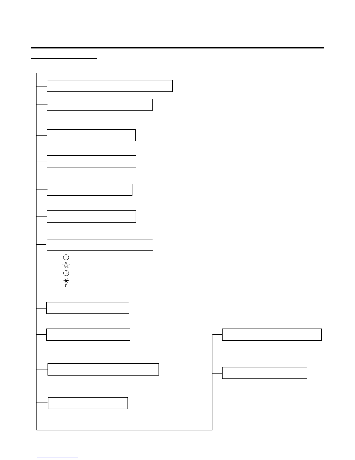
Contents
Functions
.................................................................................................................................
3
Product Specification (Cooling & Heating)
...........................................................................
6
Dimensions
..............................................................................................................................
7
Refrigeration Cycle Diagram
..................................................................................................
9
Wiring Diagram
......................................................................................................................
10
Operation Details
..................................................................................................................
12
Installation
.............................................................................................................................
27
Operation
...............................................................................................................................
41
Disassembly of the parts (Indoor Unit)
...............................................................................
43
2-way, 3-way Valve
.................................................................................................................
46
Cycle Troubleshooting Guide
...............................................................................................
53
Self-diagnosis function
.........................................................................................................
54
Electronic Parts Troubleshooting Guide
.............................................................................
56
Electronic Control Device
.....................................................................................................
67
Schematic Diagram
...............................................................................................................
73
Exploded View and Replacement Parts List
.......................................................................
78
-2-
Functions
• Room temperature sensor. (Thermistor)
• Pipe temperature sensor. (Thermistor)
• Maintain the room temperature in accordance with the Setting Temp.
• Indoor fan is delayed for 5 sec at the starting.
• Restarting is for approx. 2 minutes.
• Super High, High, Med, Low
--- Lights up in operation
--- Lights up in Sleep Mode
--- Lights up in Timer Mode
--- Lights up in Defrost Mode (for Heating Model)
• Intermittent operation of fan at low speed.
• The fan is switched to low(Cooling), low(Heating) speed.
• The unit will be stopped after 1, 2, 3, 4, 5, 6, 7 hours.
• The fan is switched to intermittent or irregular operation
•
The fan speed is automatically switched from high to low speed.
• The louver can be set at the desired position or swing
up and down automatically.
Indoor Unit
Operation ON/OFF by Remote controller
Sensing the Room Temperature
Room temperature control
Starting the Current Control
Time Delay Safety Control
Indoor Fan Speed Control
Operation indication Lamps (LED)
Soft Dry Operation Mode
• Both the indoor and outdoor fan stops
during defrosting.
• The indoor fan stops until the
evaporator pipe temperature will be
reached at 30°C.
Sleep Mode Auto Control
Natural Air Control by CHAOS Logic
Airflow Direction Control
-3-
Defrost(Deice) control (Heating)
Hot-start Control (Heating)

-4-
• If power is on, it will operate to chage capacitor (330µF/450WV) on controller and power relay will operate after about 2~5sec.
• If outdoor temp. is below 0°C, preheater is operating for 1~5min.
• At the initial, It will be operated compressor after 1min. for preheating.
• The active power filter is designed to correct power factor(cos θ) and to regulate DC link voltage.
• It will be operated PFC circuit when the compressor freq. is over 12Hz.
• If DC link voltage is not over DC 350V in 6 sec. in case of PFC on, it does not operating of compressor.
• The final operating freq. of comp. is set the lowest freq. that limited outdoor temp., discharge pipe temp.,
heat-sink temp., target freq., owing to CT.
• When the temp. of power module increases to 85°C, controller decreases Freq. of Comp.
• It will be changed the drive freq. of comp. according to temp. of indoor and outdoor.
• It will be changed the drive voltage of comp. according to operating frequency.
• It is only operated in the heating operation mode except defrosting operation.
• High speed
- Although fan motor speed is low, it will change high speed in case of below AC193V, over 45°C of out-
door temp., and over fc, fh of comp. Freq.
• Low speed
- Nomal mode and over AC270V
Outdoor Unit
Power relay control
Stand by control at low temp.
Active power filter control(PFC)
Comp. Freq. control
Overheatng. Protection(Power module)
Freq. speed control(up/down speed)
V/F control
Total current control (over current protection)
DC peak current control
4 way valve control
Outdoor fan motor control
Discharge pipe temp. control
-5-
Healthy Dehumidification Operation Mode.
( )
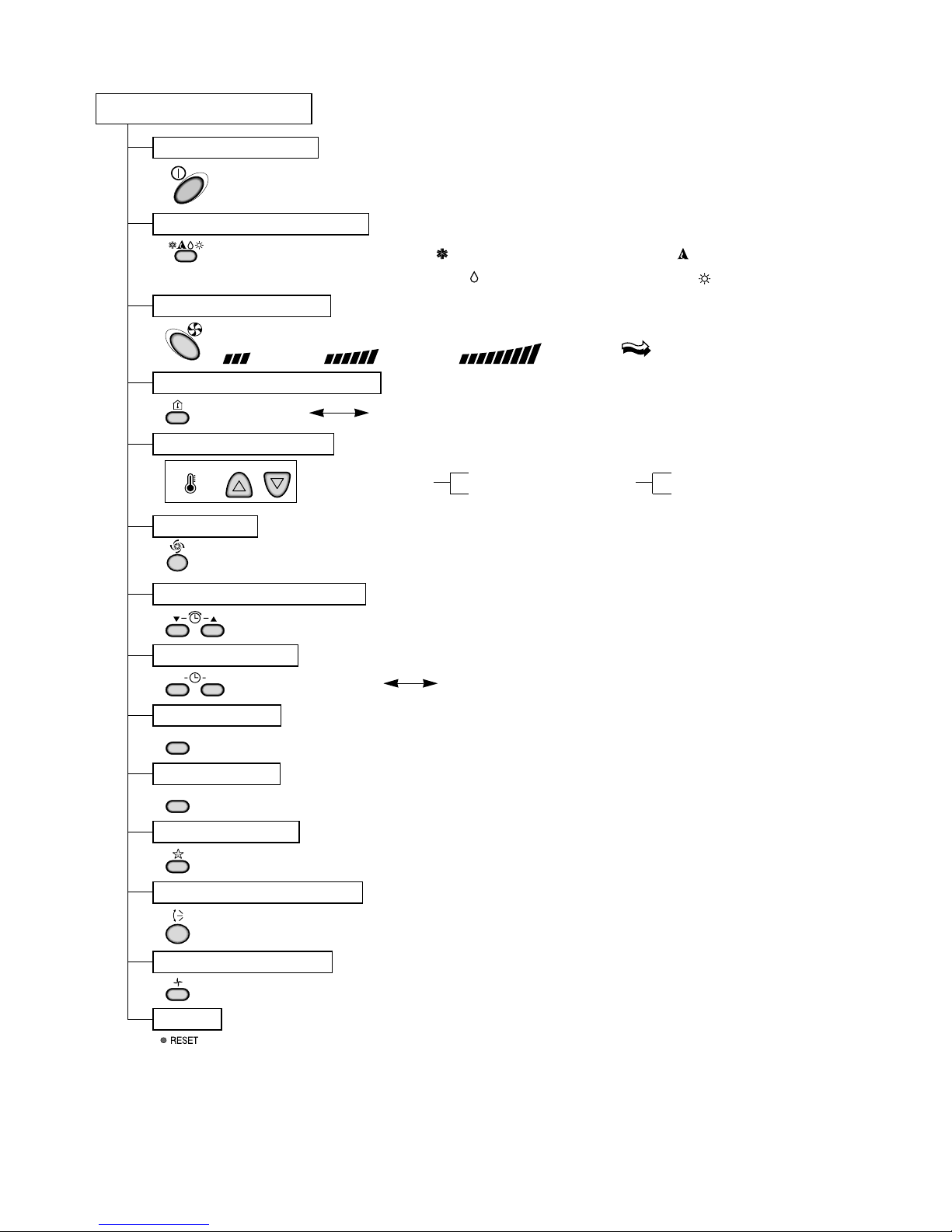
Remote Controller
Operation ON/OFF
Reset
Operation Mode Selection
Temperature Setting
Timer Selection
Timer Setting
Jet Cool
Timer Cancel
Sleep Operation
Airflow Direction Control
(Heating
model only)
TEMPERATURE
LOW HIGH
Cooling Operation Mode.( )
Heating Operation Mode.( )
Auto Operation Mode.( )
Fan Operation Mode
Room, Temperature Display
Setting the Time or Timer
ON OFF
SET
CANCEL
Fan Speed Selection
(Low) (Med) (High) (CHAOS)
: (High: 30°C LOW : 18°C)
Down to 18°C
Up to 30°C
Cooling
: OFF, ON, OFF ON
: Cancel Sleep Mode, Timer ON or Timer OFF
: 1, 2, 3, 4, 5, 6, 7, Off Timer
: Fan Operates without cooling or heating.
Down to 16°C
Up to 30°C
Heating
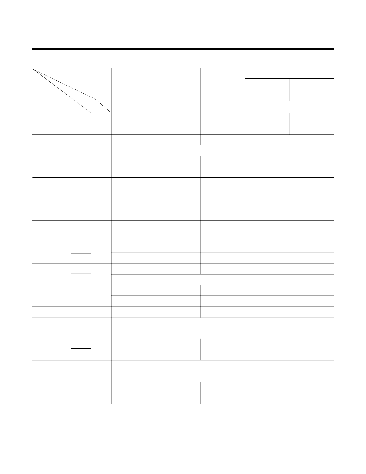
18K Series
LS-K1861YL
LS-K1860NL/YL
LS-K181N-1
LS-K18612L
7K Series 9K Series 12K Series
Cooling Capacity Btu/h
Heating Capacity
Moisture Removal l/h
Power Source Ø, V, Hz
Air Circulation Indoor m3/min
Outdoor
Noise Level Indoor dB (A)±3
Outdoor
Input Cooling W
Heating
Running Cooling A
Current Heating
Motor Output Indoor W
Outdoor
Dimensions Indoor mm
(W x H x D) Outdoor
Net. Weight Indoor kg
Outdoor
Refrigerant (R22) g
Airflow Direction Control (Up & Down)
Remocon Type
Service Valve Liquid inch(mm)
Gas
Sleeping Operation
Drain Hose
Connecting Cable mm
2
Power Cord mm
2
at 230V at 230V at 230V at 230V
7,000(4,700-8,300) 9,000(5,200-9,700) 12,000(7,500-13,200) 18,000(11,000-19,800) 17,500(11,000-19,800)
9,000(5,000-10,000) 11,250(4,600-12,500) 14,400(8,300-15,900) 27,700(12,800-22,770) 19,700(12,800-22,770)
1 1.1 1.3 2.5
1Ø, 220-240V, 50Hz
5.6 6.5 8.6 12
25 25 25 42
33 36 39 42
50 50 51 56
740 1,070 1,280 2,000
980 1,300 1,580 2,200
3.3 4.8 5.8 9.0
4.4 6 7 9.5
7.5 7.5 13 20
35.8 35.8 35.8 62
802*262*165 802*262*165 888*287*170 1,080*314*181
801*555*262 870*655*320
779 15
33 35 41 54
530 650 980 1,250
O
L.C.D Wireless
1/4''(6.35) 1/4''(6.35)
3/8''(9.52) 1/2''(12.7)
O
O
1 1.5 2.5
1 1.5 2.5
-6-
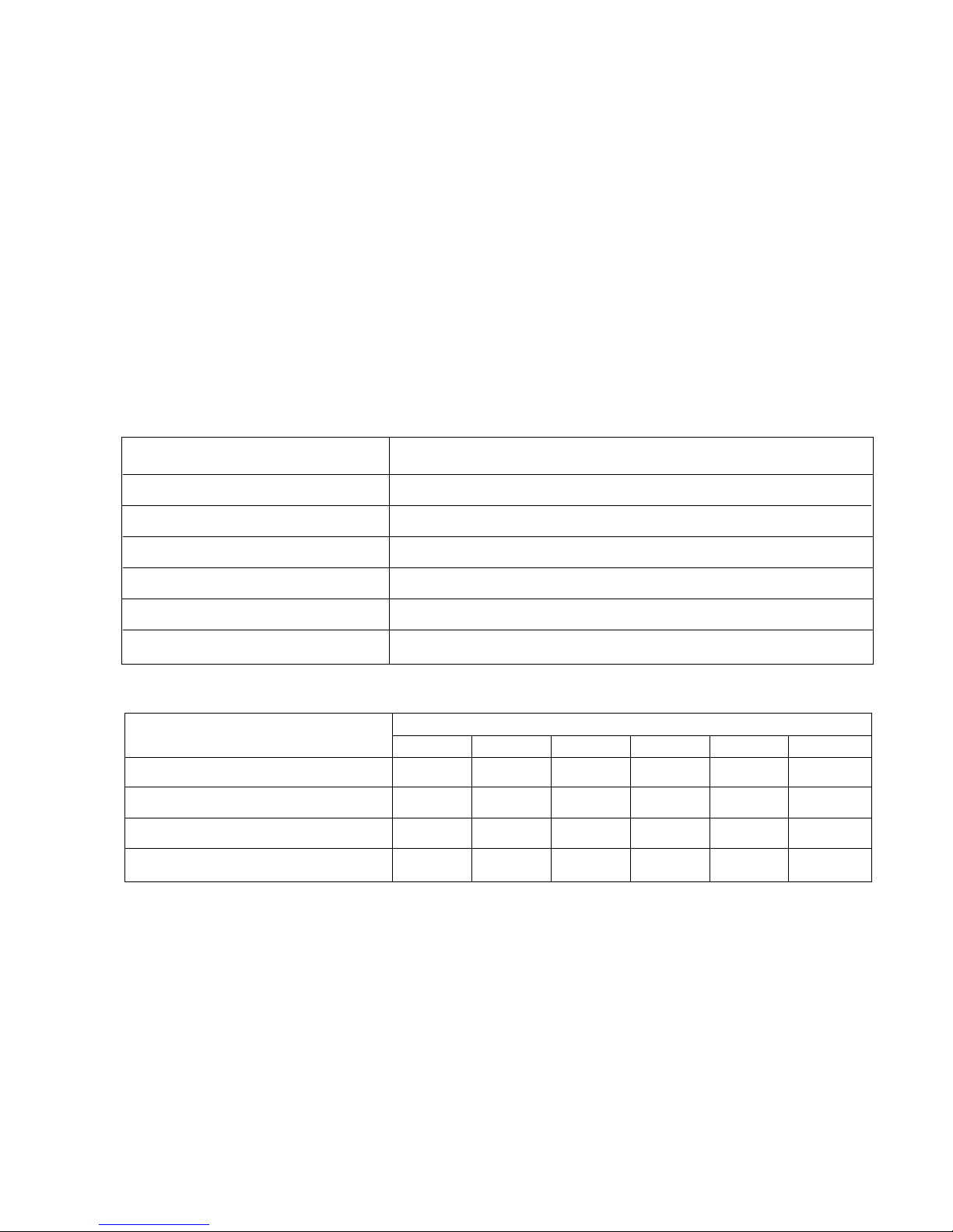
Product Specifications (Cooling & Heating)
Model Name
UnitItem
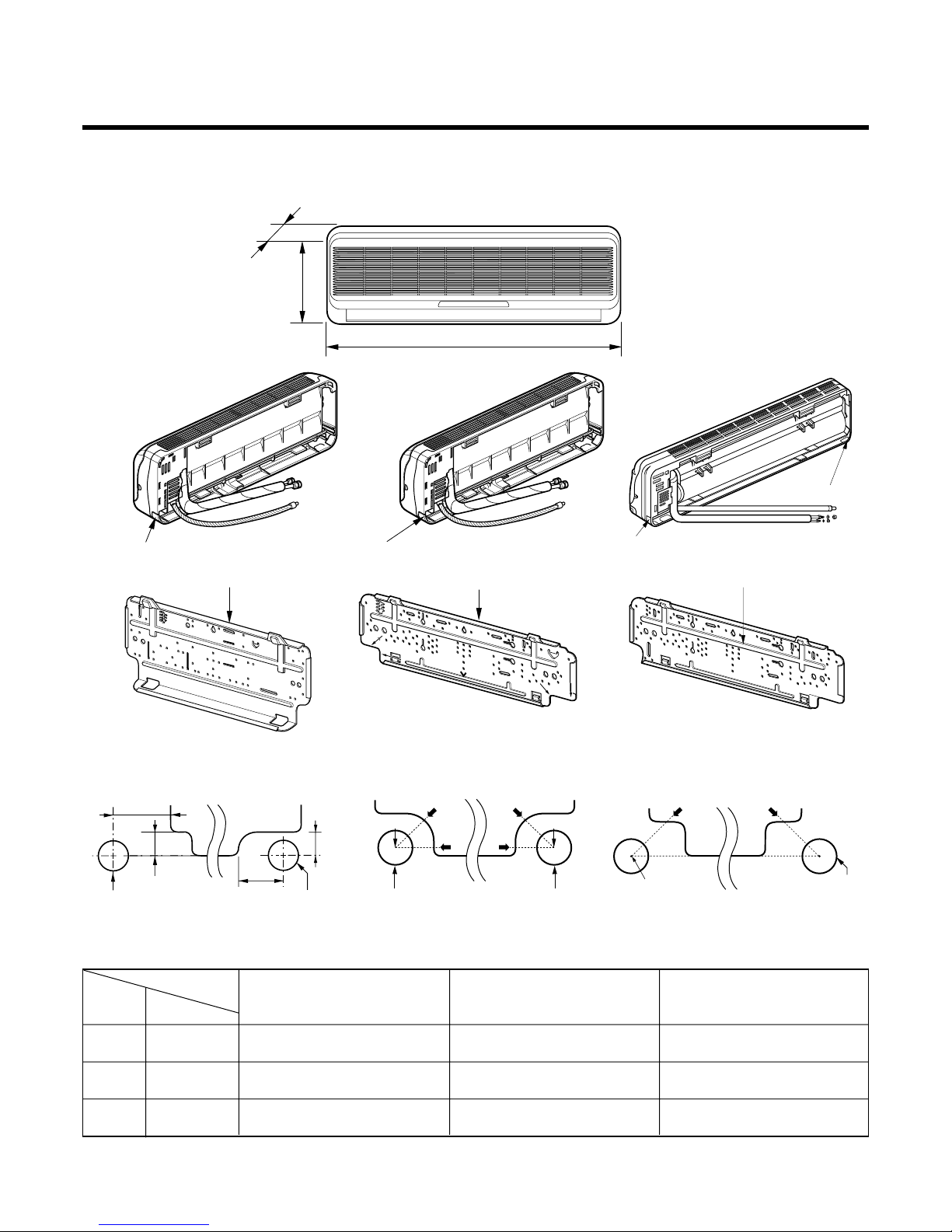
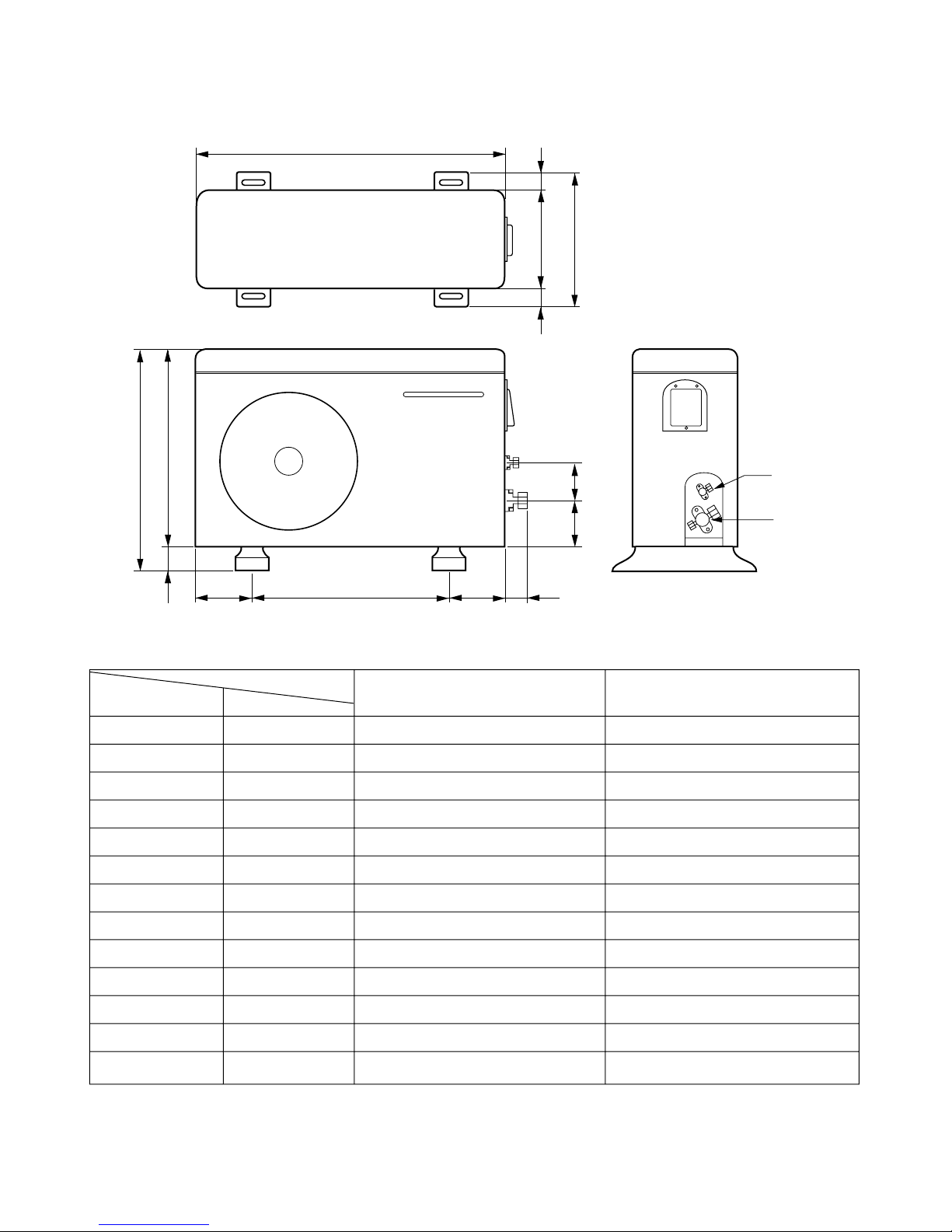
Dimensions
(1) Indoor Unit
-7-
Tubing hole cover
D
H
W
Installation plate
Tubing hole cover
Installation plate
Right rear piping
Left rear piping
ø70mm
ø70mm
50mm
20mm
20mm
80mm
ø70mm
A
A
A
A
Center
Right rear pipingLeft rear piping
Center
ø70mm
Tubing hole cover
Tubing hole cover
Installation plate
"D" "C"
Right rear pipingLeft rear piping
Hole center
ø70mm
MODEL
DIM Unit
W mm 802 888 1,080
H mm 262 287 314
D mm 165 170 181
7k, 9k Btu Series 12k Btu Series 18k Btu Series
(7k, 9k, 12k, 18k )
( 7k, 9k ) ( 12k ) ( 18k )
( 7k, 9k ) ( 12k ) ( 18k )
-8-
(2) Outdoor Unit
W
D
L1
L2
H
L3
L4
L5L6 L7 L8
L9
L10
Liquid side
2-way valve
Gas side
3-way valve
MODEL
7k, 9k, 12k Btu/h Series 18k Btu/h Series
DIM unit
W mm 801 870
H mm 555 655
D mm 262 320
L1 mm 339 370
L2 mm 37 25
L3 mm 543.6 630
L4 mm 11.4 25
L5 mm 591 546
L6 mm 105 162
L7 mm 105 162
L8 mm 72.5 54
L9 mm 86.4 79
L10 mm 77 74.5
Pipe size(Diameter:Ø)
MAX. Max
MODEL Piping length Elevation
Gas(inch) Liquid(inch)
(m) (m)
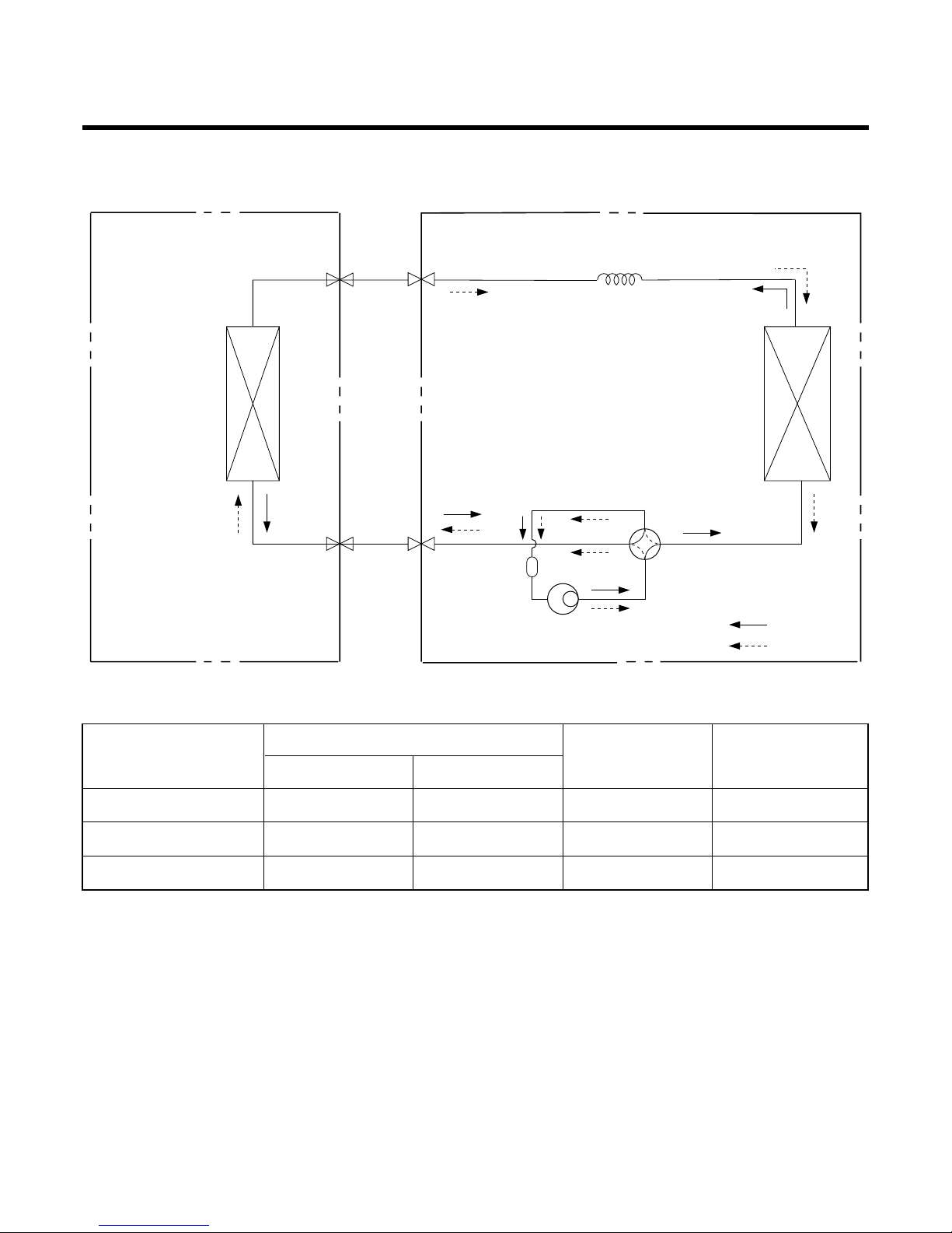
Refrigeration Cycle Diagram
-9-
INDOOR UNIT OUTDOOR UNIT
HEAT
EXCHANGE
(EVAPORATOR)
HEAT
EXCHANGE
(CONDENSER)
COMPRESSOR
ACCUMU
LATOR
GAS SIDE
3-WAY VALVE
LIQUID SIDE
2-WAY VALVE
CAPILLARY TUBE
COOLING
HEATING
REVERSING
VALVE
(Heating Model Only)
7k, 9k Btu SERIES 3/8" 1/4" 15 7
12k Btu SERIES 1/2" 1/4" 15 7
18k Btu SERIES 1/2" 1/4" 30 15
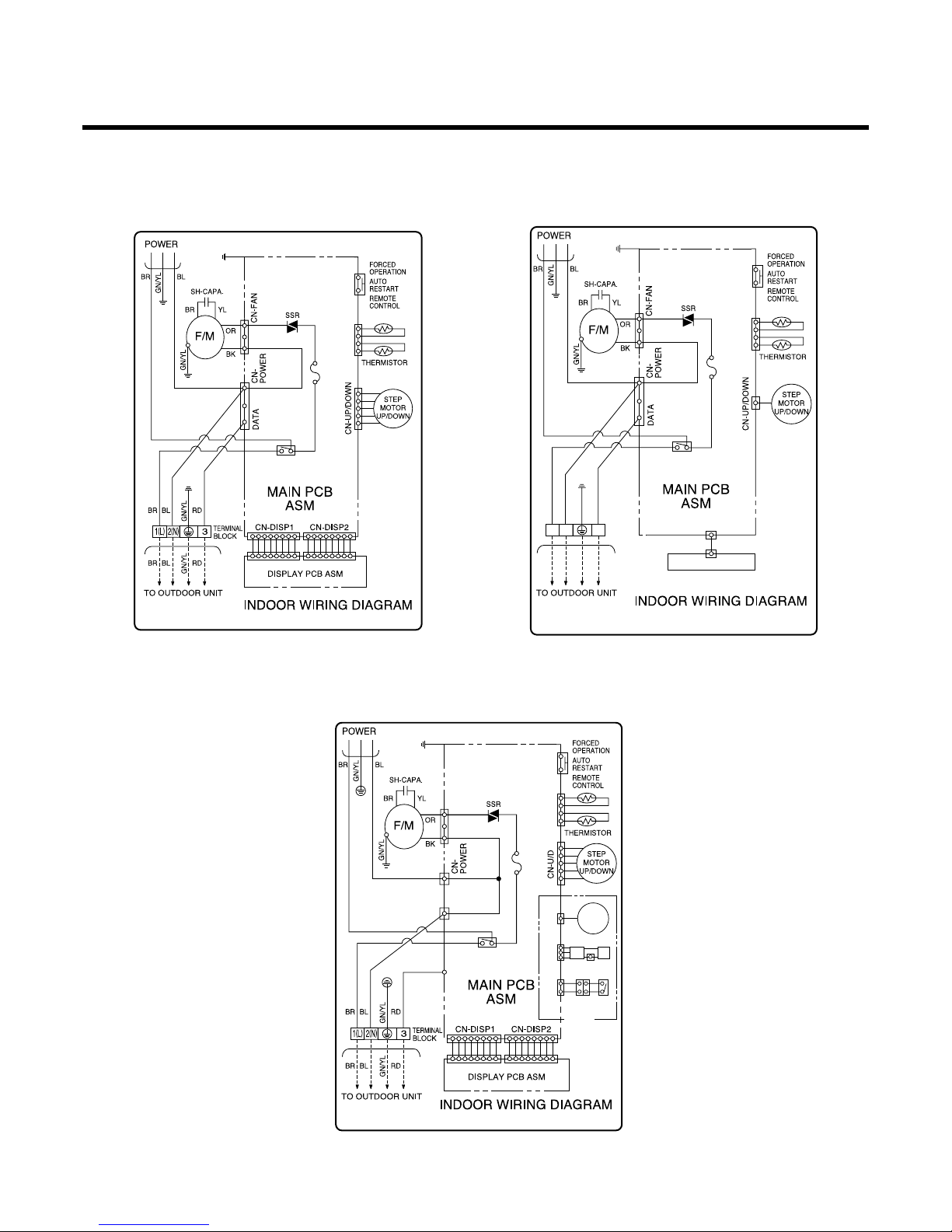
Wiring Diagram
-10-
SW01FCN-TH1
FUSE 2A,250V
P/NO:3854A90014E
RY-POWER
BK
SW01FCN-TH1
FUSE 2A, T250V
P/NO:3854A20080P
RY-POWER
BK
RD
BK BK
LIMIT
S/W
CN-L/R
STEP
MOTOR
H.V.B A/CL
OPTION
BK BK
BK BK
CN-MOTOR
CN-OUT
CN-DATA
SW01FCN-TH1
FUSE 2A,250V
P/NO:3854A20080A
RY-POWER
BK
CN-DISP1
DISPLAY PCB ASM
BRBRBL
BL
RD
RD
GN/YLGN/YL
TERMINAL
BLOCK
1(L
)
2(N
)
3
(1) Indoor Unit
LS-_NL Series (7, 9, 12K Btu) LS-_NM/NN Series (7, 9, 12K Btu)
LS-_NL/NM/NN Series (18K Btu)
LS-K18612L
-11-
CN-COMP
CN-POWER
CN-IPM
CN-OLPCN-TH1
TERMINAL
BLOCK
CN-4WAY1
RYLOW
RYHIGH
RY4WAY
RYHEAT
CN-HEAT
BR
BL
BR
BL
GN/YL
RD
BR
BR
BK BK
SPECIAL FUSE
(15A,250V)
BL
GN/YL
RD
BR
GN/YL
OR
YL BL BK
F/M
CN-AC
NOISE
FILTER
1(L
)
2(N
)
3
TO
INDOOR
UNIT
MAIN PWB ASM
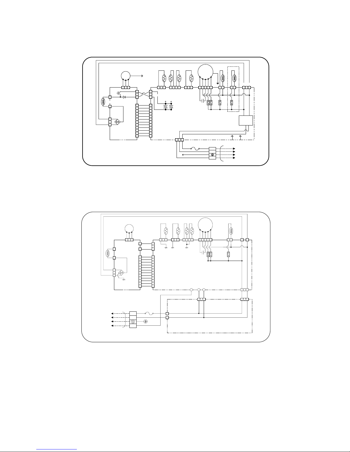
OUTDOOR WIRING DIAGRAM
P/NO : 3854A20080B
(3854A90014G)
SUB PWB
CAPACITOR
CN-DC
CN-DC
CN-UVW
RD
YL
YL
YL
BL
BR
CN-AC
IGB T
C/COIL
COMP
GN/YL
RD BL YL
CN-COMP
CN-UVW
U
V
W
CN-PWR1
CN-PWR1
CN-DATA
CN-AC1
CN-AC2
CN-IPM
CN-TH2 CN-TH1 CN-4WAY
RYLOW
WCN3 WCN1 WCN2
RYHIGH
RY4WAY
CN-SUB1 CN-SUB2
3854A20080T
SUB
PWB
FILTER PWB ASM
MAIN PWB ASM
F/M
OUTDOOR WIRING DIAGRAM
CN-DC
CN-SUB
C/COIL
1(L
)
2(N
)
3
INDOOR
UNIT
SPECIAL FUSE
AC250V/20A
COMP
RD
BR
BR
TERMINAL
BLOCK
BL
GN/YL
RD
BR
BL
GN/YL
RD
BL
BL YL
BK
RD
BR BL BR BL
BR BL
BRORYL BL BK
(2) Outdoor Unit
LS-_NL/NM/NN Series (7, 9, 12K Btu)
(2) Outdoor Unit
LS-_NL/NM/NN Series (18K Btu), LS-K18612L
Operation Details
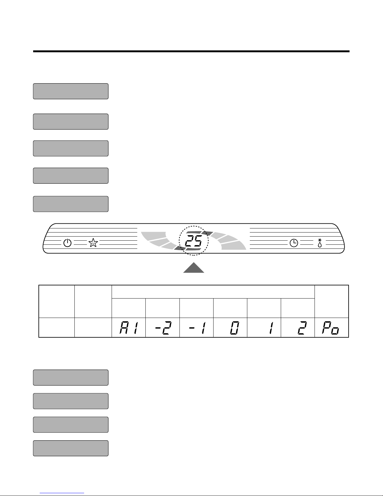
1. LED display of indoor unit
■ LS-_NL Series
■ LS-_NM/NN Series
-12-
A.I operation mode
Operation
Indicator
Shape of
display
Cooling
heating
dehumidifi-
cation
Setting
temp.
Standard Too hot Hot
Comfor-
table
Cold Too cold
Jet cool
Operation Indicator
Sleep Timer Indicator
Timer Indicator
Defrost Indicator
Setting Temp.
• On while in appliance operation, off while in appliance pause.
• Blinking(3sec off/0.5sec on) according to Error Code as long as the system mal-
functions.
• On while in sleep timer mode, off when sleep timer cancel or appliance operation
pause.
• On while in timer mode(on/off), off when timer mode is completed or canceled.
• Off except when hot start during heating mode operation or while in defrost control.
• Cooling/heating/dehumidification mode : setting temperature from remote control
• Fuzzy operation mode : fuzzy key data(5sec on) ➔ AI
Operation Indicator
Sleep Timer Indicator
Timer Indicator
Defrost Indicator
• On while in appliance operation, off while in appliance pause.
• Flashing while in disconnection or short in Thermistor. (3 sec off/0.5 sec on)
• On while in sleep timer mode, off when sleep timer cancel or appliance operation
pause.
• On while in timer mode(on/off), off when timer mode is completed or canceled.
• Off except when hot start during heating mode operation or while in defrost control.
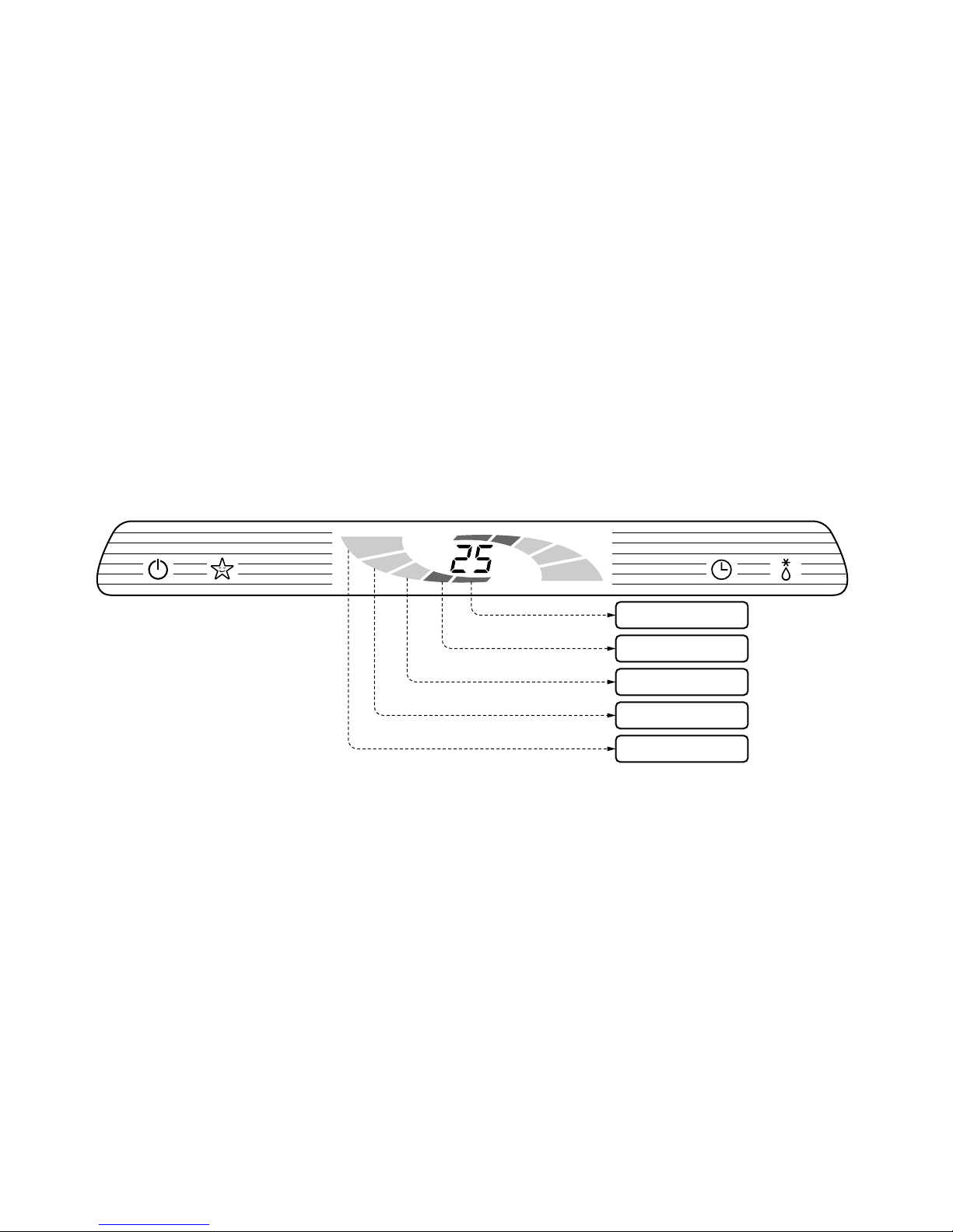
■ How to operate the power display (LS-_NL Series)
• It must be displayed the power level that will be operating frequency of compressor.
• It indicates power levels that compressor operating frequency is controlled to depend on indoor and outdoor
conditions.
• It is displayed as below.
❐ Heat mode operation
- Power level 1: below Step 3 of COMP. operating frequency
- Power level 2: below Step 6 of COMP. operating frequency
- Power level 3: below Step 10 of COMP. operating frequency
- Power level 4: below Step 14 of COMP. operating frequency
- Power level 5: over Step 14 of COMP. operating frequency
❐ Operation mode except heat mode operation
- Power level 1: below Step 2 of COMP. operating frequency
- Power level 2: below Step 8 of COMP. operating frequency
- Power level 3: below Step 10 of COMP. operating frequency
- Power level 4: below Step 12 of COMP. operating frequency
- Power level 5: over Step 12 of COMP. operating frequency
-13-
Power Level 1
Power Level 2
Power Level 3
Power Level 4
Power Level 5
-14-
2. Protection of the evaporator pipe from frosting
• If the indoor pipe temperaure is below 0°C in 7 min. after the compressor operates without pause while in
cooling cycle operation mode,
➔ compressor, outdoor fan are turned off.
• When indoor pipe temp. is 7°C or higher after 2 min pause of compressor
➔ compressor, outdoor fan is turned on according to the condition of the room temperature.
3. Protection of the indoor fan from droplet formation (Enclosure
sweat and condensed disposal test)
• Control condition : The system operates standard operation without this condition as follows.
- Setting temperature <25°C
- Indoor fan speed ≤ low speed
- Outdoor temperature < 31°C
• Control method
- Operation frequency of compressor must be below ➃ (refer to the comp. Freq. table)
- The indoor fan operates at medium speed.
Comp. free
Comp. off
0˚C
7˚C
Indoor pipe
temp.
Comp. free
Comp. Step 4
3˚C
3°C
Indoor pipe
temp.
-15-
4. Cooling mode operation
• Operating frequency of compressor depend on the difference of the temperature.
(= intake air Temp.- Compressor off Temp.
• Compressor off temp.= setting temp. -0.5°C
on temp. = setting temp. +0.5°C
• If compressor operates at some operating frequency, the operating frequency of compressor cannot be
changed within 30 seconds.
• Condition of compressor turned off
- When intake air temperature stay at the temperature between setting temp.
-
0.5°C and setting temp.
-
1.0°C for 3 minutes continuously.
- When intake air temperature reaches below the temperature of setting temp.
-
1.0°C.
• Compressor 2 minutes delay
- The compressor can restart minimum 2 minutes later after compressor off.
Temp. differences
over 2.5°C
2.0~2.49°C
1.5~1.99°C
1.0~1.49°C
0.5~0.99°C
0.0~0.49°C
Comp. Operating frequency
Step 12
Step 10
Step 8
Step 4
Step 2
Step 1
[The operating freq. step of comp.]
[The targeting operating freq. of comp. each model]
Model
7K Btu Series
9K Btu Series
12K Btu Series
18K Btu Series
Comp. Operating frequency
40 47 54 64 74 85
45 53 72 86 95 110
35 47 51 58 62 67
35 47 57 66 71 96
Step 1 Step 2 Step 4 Step 8
(Fc)
Step 10 Step 12
-16-
5. Healthy Dehumidification mode operation
• When the dehumidification operation is set by the remote controller the intake air temperature is detected and
the setting temp. is automatically set according to the intake air temperature.
• Operating frequency of compressor and indoor fan speed.
Temp. differences
32°C ≤ intake air temp.
26°C ≤ intake air temp. < 32°C
24°C ≤ intake air temp.< 26°C
18°C < intake air temp. < 24°C
intake air temp. ≤ 18°C
Comp. Operating frequency
25°C
25°C
intake air temp. -1°C
intake air temp. -0.5°C
18°C
Cooling operation area
Dehumidification
operation area
After 3 min off
OFF instantly
Low
speed
Low
speed
After 5 min OFF
low speed
Setting
speed
+
1.0˚C
+
0.5˚C
Setting temp. +
0˚C
-
1.0˚C
-
2.0˚C
Operating frequency of compressor Indoor fan speed
Step 3
Step 2
Step 1
-17-
6. Heating mode operation
• Operating frequency of compressor depend on the difference of the temperature
(= compressor off temp. - intake air temp.)
• Compressor off temp. = setting temp.+3.0°C
on temp. = setting temp.
• If compressor operates at some operation frequency, the operating frequency of compressor cannot be
changed within 30 seconds.
• Condition of compressor turned off
- When intake air temperature reaches +3°C above the setting temperature.
• Condition of indoor fan turned off
- While in compressor on:indoor pipe temp. < 26°C
off: indoor pipe temp. < 37°C
• While in defrost control, between the indoor and outdoor fans are turned off.
• Compressor 2minutes delay
- After compressor off, the compressor can restart minimum 2 minutes later.
Temp. differences
over 3.0°C
2.5~3.0°C
2.0~2.49°C
1.5~1.99°C
1.0~1.49°C
0.5~0.99°C
0.0~0.49°C
Comp. Operating frequency
Step 19
Step 15
Step 13
Step 9
Step 5
Step 3
Step 1
[ The operating freq. step of comp]
[The targeting operating freq. of comp. each model]
Model
7K Btu Series
9K Btu Series
12K Btu Series
18K Btu Series
Comp. Operating frequency
42 47 56 67 80 86 90
42 56 68 82 95 103 110
41 49 57 64 72 76 83
41 47 53 58 67 71 76
Step 1 Step 3 Step 5 Step 9
Step 13(Fh)
Step 15 Step 19
-18-
7. Fuzzy mode operation
• When any of operation mode is not selected like the moment of the power on or when the unit turned off, the
operation mode is selected.
• When determining the operation mode, the compressor, outdoor fan are off and only the indoor fan is operated for 15seconds, then an operation mode is selected according to.
Basis of determining operating mode
Outdoor temp.
over 24°C
21~24°C
18~21°C
below 18°C
Operating Mode
Cooling
Healthy Dehumidification
intake air temp. ≥ 25°C …Dehumidification
intake air temp. < 25°C … Heating
Heating
7.1 Fuzzy operation for cooling
• According to the setting temperature selected by Fuzzy rule, the operating frequency of compressor is determined like cooling mode operation.
• At the beginning of Fuzzy mode operation, the setting temperature is automatically selected according to the
intake air temperature at that time.
• When the Fuzzy key(=setting temp. key) is input after the initial setting temperature is selected, the Fuzzy
key value and intake air temperature at that time are compared to select the setting temperature automatically
according to the fuzzy rule.
• While in Fuzzy operation, the air flow speed of the indoor fan is automatically operated by chaos logic.
at beginning
during opertion
Intake air temp.
over 26°C
18~26°C
below 18°C
18~30°C
below 18°C
over 30°C
Setting temp.
25°C
intake air temp. -05°C
18°C
Fuzzy rule
18°C Fuzzy rule
30°C Fuzzy rule
Fan speed
CHAOS airflow

-19-
7.2 Fuzzy operation for Heating
• According to the setting temperature selected by Fuzzy rule, the operating frequency of compressor is determined like heating mode operation.
• At the beginning of Fuzzy mode operation, the setting temperature is automatically selected according to the
intake air temperature at that time.
• When the Fuzzy key(=setting temp. key) is input after the initial setting temperature is selected, the Fuzzy key
value and intake air temperature at that time are compared to select the setting temperature automatically
according to the Fuzzy rule.
• While in Fuzzy operation, the airflow speed of the indoor fan is automatically operated by CHAOS logic.
at beginning
during opertion
Outdoor temp.
over 26°C
0~5°C
-5~0°C
below -5°C
16~30°C
below 16°C
over 30°C
Setting temp.
intake air temp. +0.5°C
intake air temp. +1.0°C
intake air temp. +1.5°C
intake air temp. +2.0°C
Fuzzy rule
16°C Fuzzy rule
30°C Fuzzy rule
Fan speed
CHAOS airflow
7.3 Fuzzy operation for dehumidification
• At the beginning of Fuzzy mode operation, the setting temperature is automatically selected according to the
intake air temperature at that time.
• According to the setting temperature selected by Fuzzy rule, the operating frequency of compressor is determined like dehumidefication mode operation.
at beginning
during operation
Outdoor temp.
over 26°C
18~26°C
below 18°C
Setting temp.
25°C
intake air temp. -0.5°C
18°C
same as dehumidification mode
Fan speed
CHAOS airflow
-20-
8. Jet cool mode operation
• While in heating mode or Fuzzy operation, the Jet Cool key cannot be input. When it is input while in the
other mode operation(cooling, dehumidification, ventilation), the Jet Cool mode is operated.
• In the Jet Cool mode, the indoor fan is operated super-high speed for 30 min. at cooling mode operation.
• In the Jet Cool mode, the room temperature is controlled to the setting temperature, 18°C.
• When the sleep timer mode input while the Jet Cool mode operation, the Jet Cool mode has the priority.
• When the Jet Cool key is input, the upper/lower vane is reset to those of the initial cooling mode and then
operated in order that the air outflow could reach further.
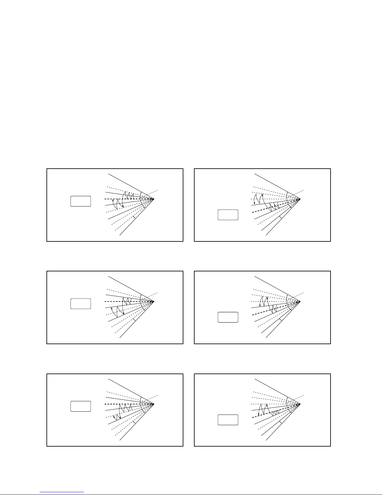
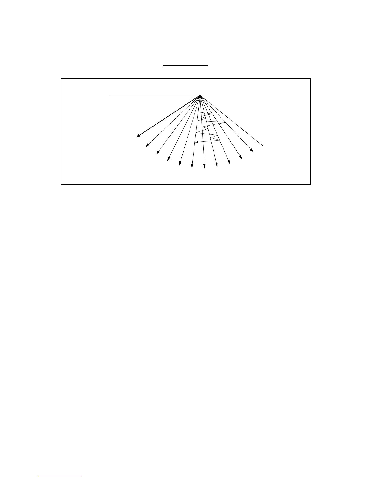
9. Swing mode
9.1 Chaos swing mode of not fuzzy mode operation
• By the Chaos swing key input, the upper/lower vane automatically operates with the Chaos swing or it is fixed
to the desired direction.
Closed
Open
Mode 1
Mode 2
Mode 3
Mode 4
Mode 5
Mode 6
Mode 7
Beginning
of cooling
Mode 8
< Cooling Mode >
Chaos swing of 7K, 9K Btu Series
Chaos swing of 12K Btu Series
8°
135°
< Heating Mode >
Closed
Open
Mode 1
Mode 2
Mode 3
Mode 4
Mode 5
Mode 6
Mode 7
Beginning
of heating
Mode 8
8°
135°
Closed
Open
Mode 1
Mode 2
Mode 3
Mode 4
Mode 5
Mode 6
Mode 7
Beginning
of cooling
Mode 8
< Cooling Mode >
7°
125°
< Heating Mode >
Closed
Open
Mode 1
Mode 2
Mode 3
Mode 4
Mode 5
Mode 6
Mode 7
Beginning
of heating
Mode 8
7°
125°
Chaos swing of 18K Btu Series
Closed
Open
Mode 1
Mode 2
Mode 3
Mode 4
Mode 5
Mode 6
Mode 7
Beginning
of cooling
Mode 8
< Cooling Mode >
7°
125°
< Heating Mode >
Closed
Open
Mode 1
Mode 2
Mode 3
Mode 4
Mode 5
Mode 6
Mode 7
Beginning
of heating
Mode 8
7°
125°
9.2 Auto swing of Fuzzy mode operation
• While in Fuzzy mode operation, Chaos swing is operated according to 1/f fluctuation.
1/f fluctuation
-21-
MODE00
(Open)
MODE01
MODE02
MODE03
MODE04
MODE05
MODE06
MODE08
MODE09
MODE10
MODE11
MODE12
MODE13
MODE14
MODE15
MODE16
MODE17
(
Closed
)
MODE07
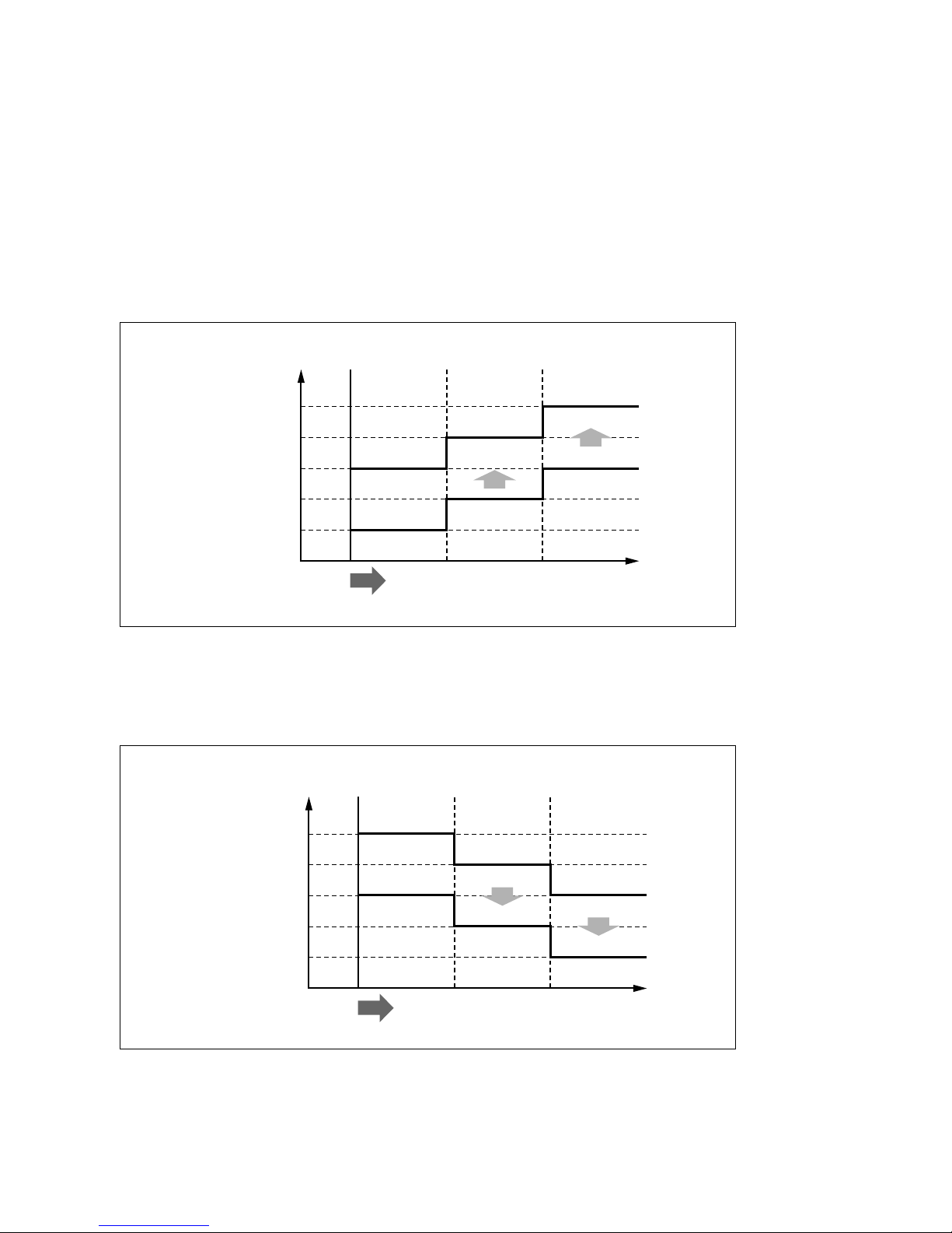
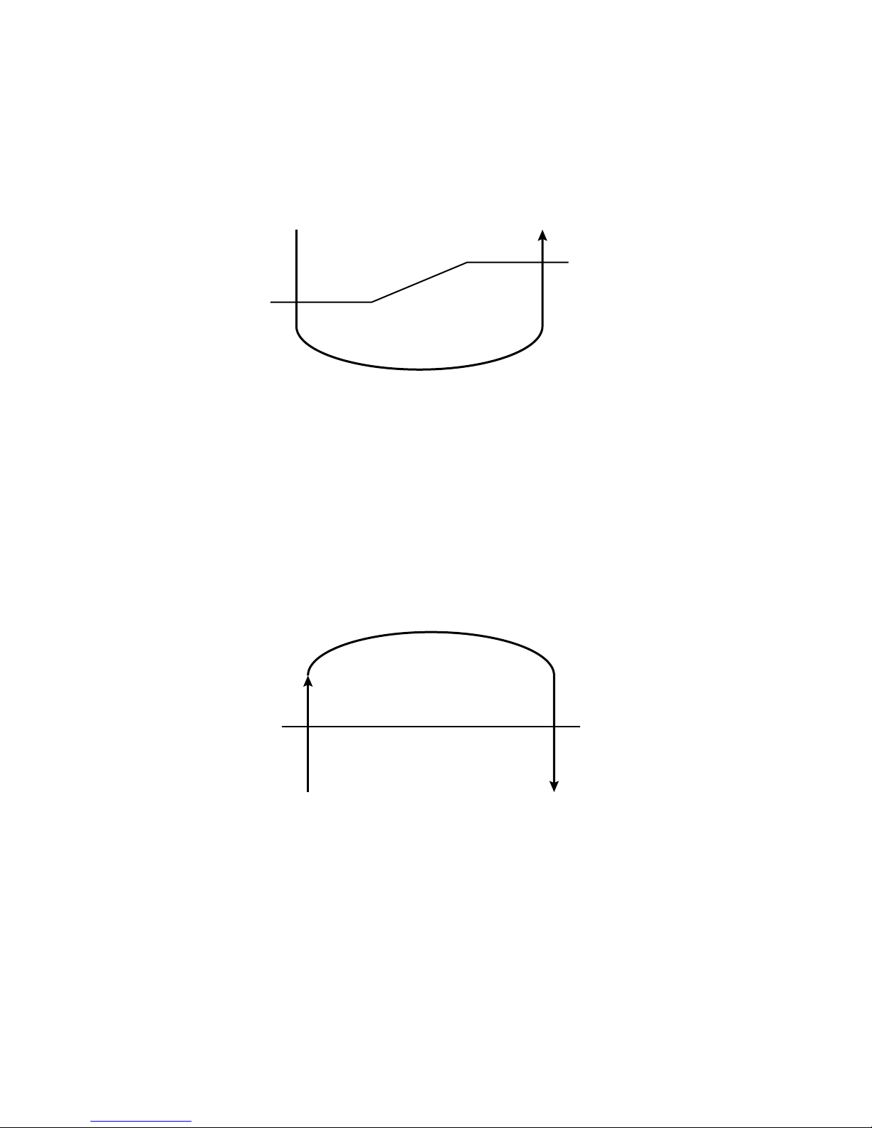
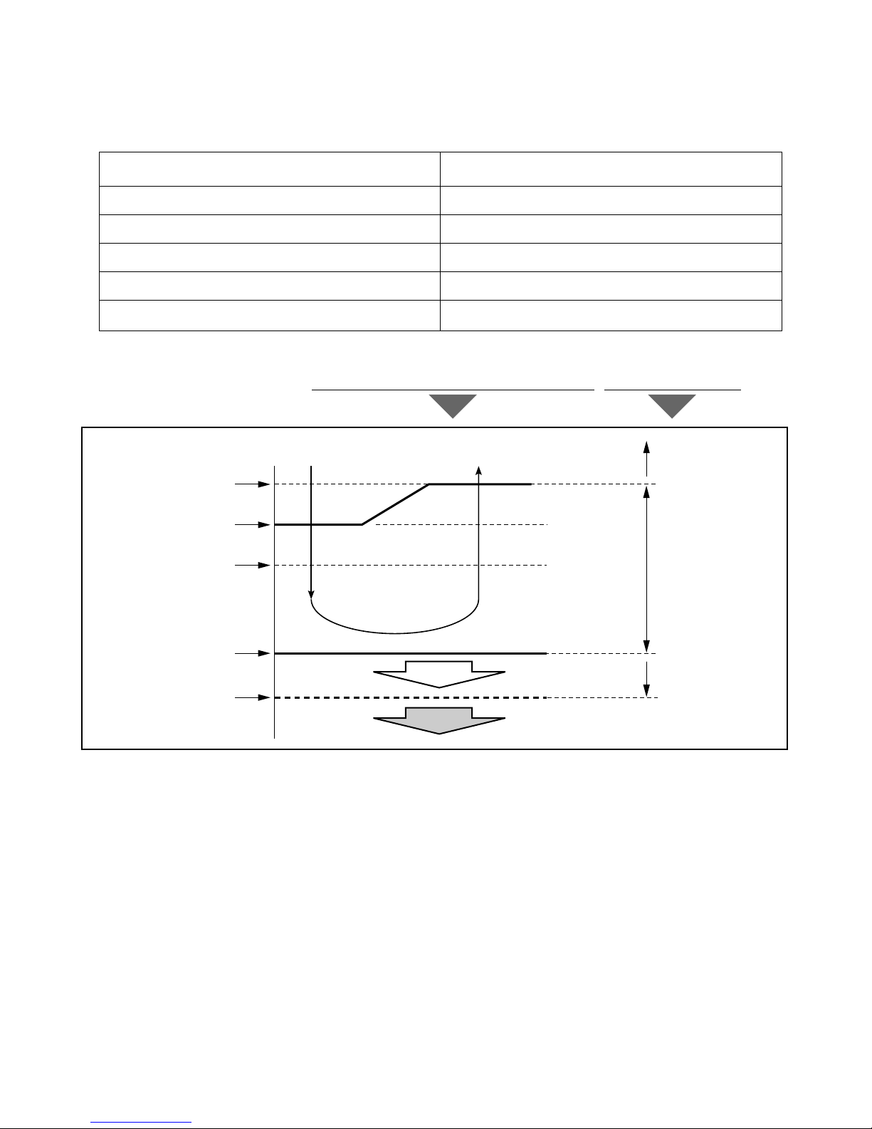
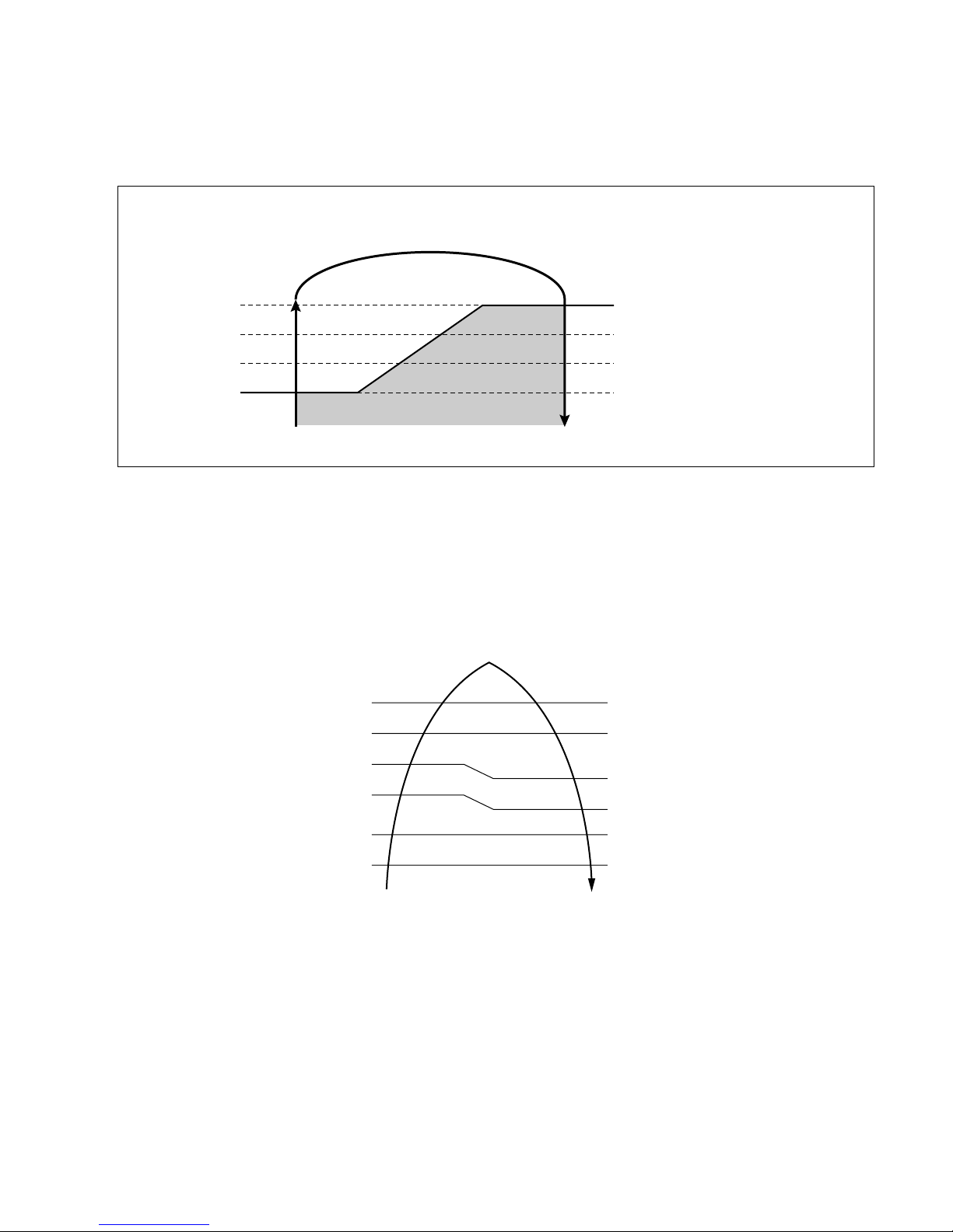
10.1 Sleep timer operation for cooling cycle
• While in cooling mode operation, 60 min. later since the start of the sleep timer, the setting temperature
increase by 0.5°C. After another 60min. elapse, it increases by 1°C again.
10.2 Sleep timer operation for heating cycle
• While in heating mode operation, 60 min. later since the start of the sleep timer, the setting temperature
decrease by 0.5°C. After another 60min. elapse, it decreases by 1°C again.
-22-
Setting temp. (˚C)
0.5˚C up
0.1˚C up
Cooling ON temp.
(Setting temp. +0.5˚C)
Cooling OFF temp.
(Setting temp. -0.5˚C)
1 2 Sleep time (hr
)
Setting temp. (˚C)
Heating ON temp.
(Setting temp)
Heating OFF temp.
(Setting temp. +3.0˚C)
1 2 Sleep time (hr
)
0.5˚C down
1.0˚C down
10. Sleep timer operation
• When the sleep time is reached after [1,2,3,4,5,6,7hr] is input by the remote control during the operation, the
operation of the appliance stops.
• When the appliance is on pause, the sleep timer mode cannot be input.
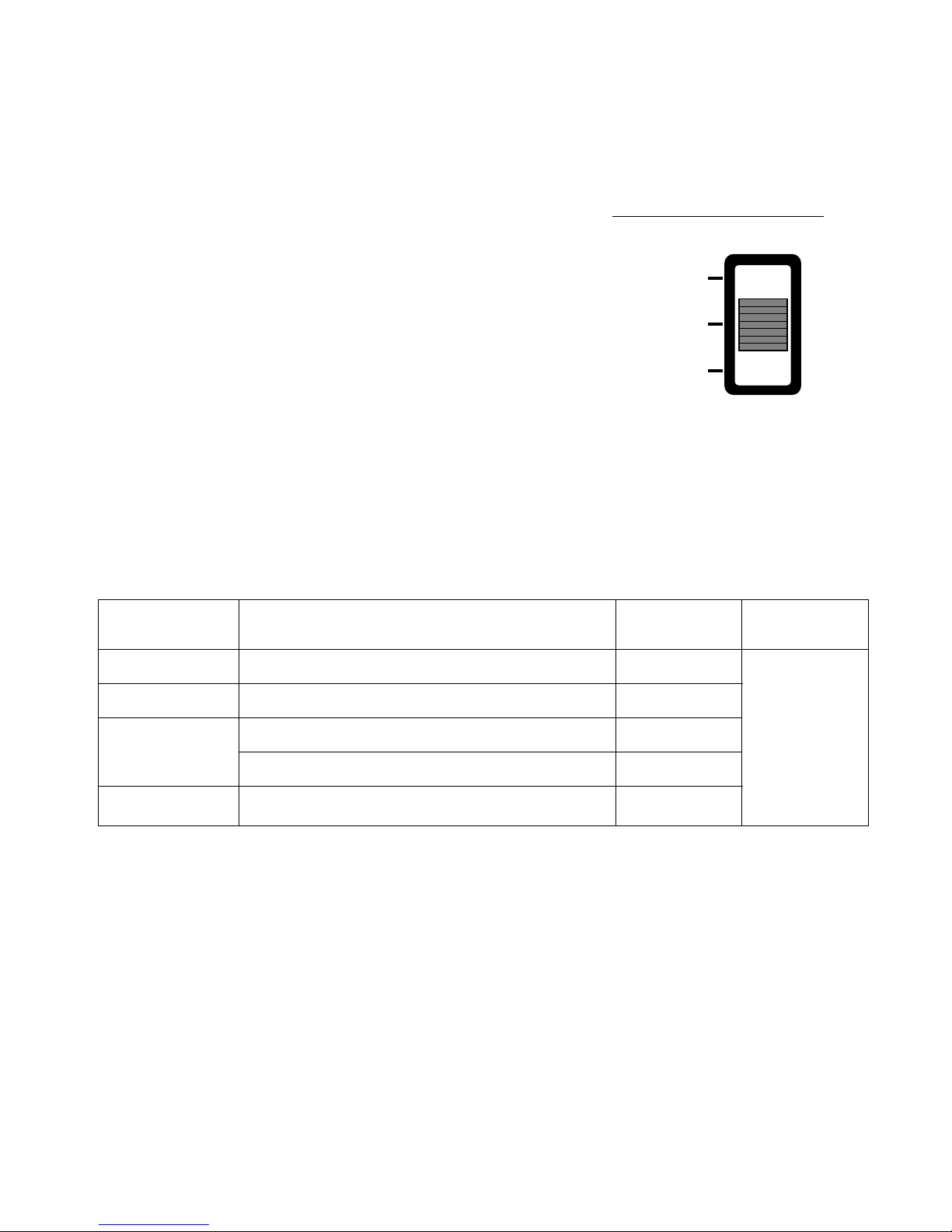
11. Auto restarting operation
• When the power is restarted after a sudden power failure while in appliance operation, the mode before the
power failure is kept on the memory and the appliance automatically operates in the mode on the memory.
• The slide switch on the indoor unit of the appliance should be on the AUTO RESTART position in order that
the Auto restarting operation is available.
• Operation mode that is kept on the memory
— State of operation ON/OFF
— Operation mode/setting temp./selected airflow speed
— Sleep timer mode/remaining time of sleep timer
12. Forced operation
• To operate the appliance by force in case that the remote control is lost, the forced operation selection switch
is on the main unit of the appliance to operate the appliance in the standard conditions.
• The operation condition is set according to the outdoor temp. and intake air temperature as follows.
-23-
Outdoor temp.
over 24°C
21~24°C
18~21°C
below 18°C
Setting temp.
22°C
23°C
23°C
24°C
24°C
Setting speed of
indoor fan
High speed
Operating Mode
Cooling
Healthy Dehumidification
Intake air temp. ≥ 25°C ➔ Dehumidification
Intake air temp. < 25°C ➔ Heating
Heating
FORCED
OPERATION
AUTO
RESTART
REMOTE
CONTROL
Slide Switch of indoor unit
13. Power relay control
• Power relay turns on 1 second later after the power is input to the outdoor unit.
• Control sequence : power on
➔ PTC operating ➔ power relay on
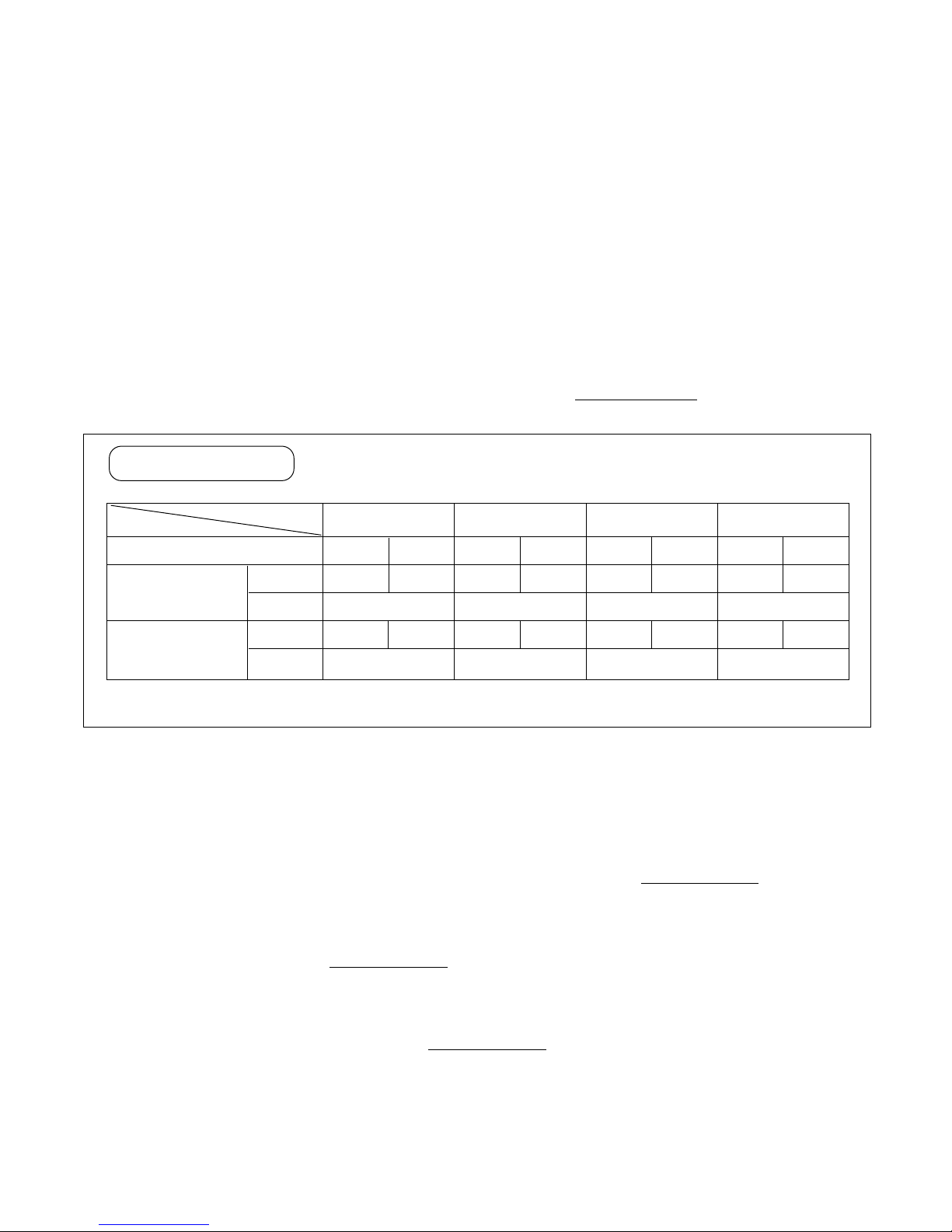
14. Protection from total current control
■ CT1 control
• If the operating current reaches I1, the operating frequency of the compressor decrease.
• After decreasing the operating frequency by 1step, if operating current is below I1 for 24 seconds continuous-
ly, the operating frequency of compressor increase by 1step.
■ CT2 control
• If the operating current of the appliance reaches I2, the compressor stop instantly and 2 minutes later the
compressor restart again.
• If CT2 occurs twice within 1hour, the appliance turn off and display ERROR CODE 7.
-24-
Model
7K Btu Series 9K Btu Series 12K Btu Series 18K Btu Series
Cooling Heating
8.5A 10A
11.5A
8A 9.5A
11.5A
Cooling Heating
9A 10.5A
13.5A
8.5A 10A
13.5A
Cooling Heating
10.5A 12A
13.5A
10A 11.5A
13.5A
Cooling Heating
12.5A 14A
16A
12A 13.5A
16A
Operating mode
below 38°C
(outdoor temp.)
I1
I2
I1
I2
over 38°C
(outdoor temp.)
Condition
❇ I1:Current of operating frequency down
I2: Current of compressor cut off
cf. I1 is set the lowest level between intial value and in case dectection of dc paeak current.
Control table
15. Protection from DC Peak Current
■ DC Peak Current Error by a fault signal of IPM
• If the operating current of IPM reaches 35A ±3A, the compressor stop instantly.
• If DC PEAK occurs 3 times within 1 hour, the appliance turns off and display ERROR CODE 6.
■ DC Peak Current Error b y the compressor lock
• If the DC LINK voltage below DC 350V occurs 5 times within 1 hour while the compressor is operating, the
appliance turns off and display ERROR CODE 6.
■ DC Peak Current Error b y the Outdoor Fan Lock
• If it’s 5 times within 1 hour in case of the temperature of outdoor pipe TH is over 65°C while the compressor is
operating, the appliance turns off and display ERROR CODE 6.
16. Portection from overheating of power module
• If the temperature of the heat sink TH. reaches over Toff, the Compressor stop instantly.
• It will be limited the compressor operating frequency according to the heat sink TH.(refer to below FIG.)
• It will be blink 4 times, when the thermistor is open or short, also the temperature is over Toff.
17. Portection from overheating of compressor
• If the temperature of the discharge pipe of compressor reaches over 130°C or below -30°C the compressor
stop instantly.
• It will be limited the compressor operating frequency according to the compressor dome TH.(Refer to below
Fig.)
-25-
Comp. off
Comp. free
Fc-1
Fc-2
Target frequency
Toff (84°C)
Ton + 2°C (78°C)
Ton + 5°C (81°C)
Ton (76°C)
130°C
118°C
111°C
108°C
-13°C
-30°C
101°C
93°C
Fhmin
OFF
OFF
0Hz
Fc-2
Fc-1
Setting frequency
[The control graph from heat–sink TH]
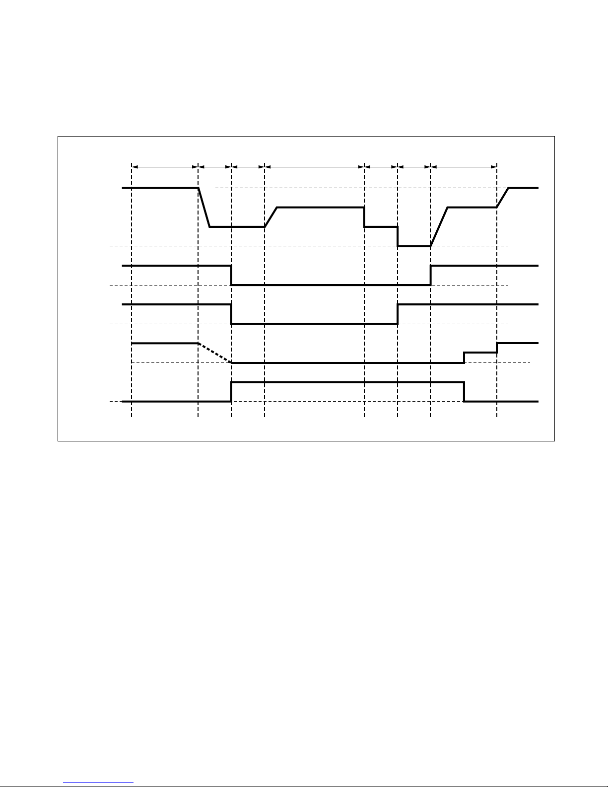
18 . Defrosting control
• While in heating mode operation in order to protect the evaporator pipe of the outdoor unit from freezing,
reversed to cooling cycle to defrost the evaporator pipe of the outdoor unit.
• Defrosting control is available 50 minutes later since heating cycle started and the pipe temperature of outdoor unit reaches below -6°C.
-26-
50 min
Setting frequency
Setting speed
Setting
speed
OFF OFF
ON
OFF
OFF(Cooling cycle)
Setting
frequency
30 sec
Fc-1 step
Operating
frequency
of compressor
4 Wa y valve
Outdoor fan
Indoor fan
Defrost LED
Fc-1
Fh+1
OFF
ON ON(Heating cycle)
ON ON
Low
(FhMAX-2 or
FhMAX-3)
30 sec 30 sec
8 min or
over 25˚C(120sec)
30 sec 1 min
 Loading...