

Lg LSG4511BD Installation
INSTALLATION
13
INSTALLATION
Before Installing the Range
Make sure your range is properly installed and grounded by a qualified installer, according to the installation
instructions. Any adjustment and service should be performed only by qualified gas range installers or service
technicians.
In the Commonwealth of Massachusetts
•This product must be installed by a licensed plumber or gas fitter.
•When using ball type gas shut-off valves, they must be the T-handle type.
•When using a flexible gas connector, it must not exceed 3 feet in length.
Preparing for Installation
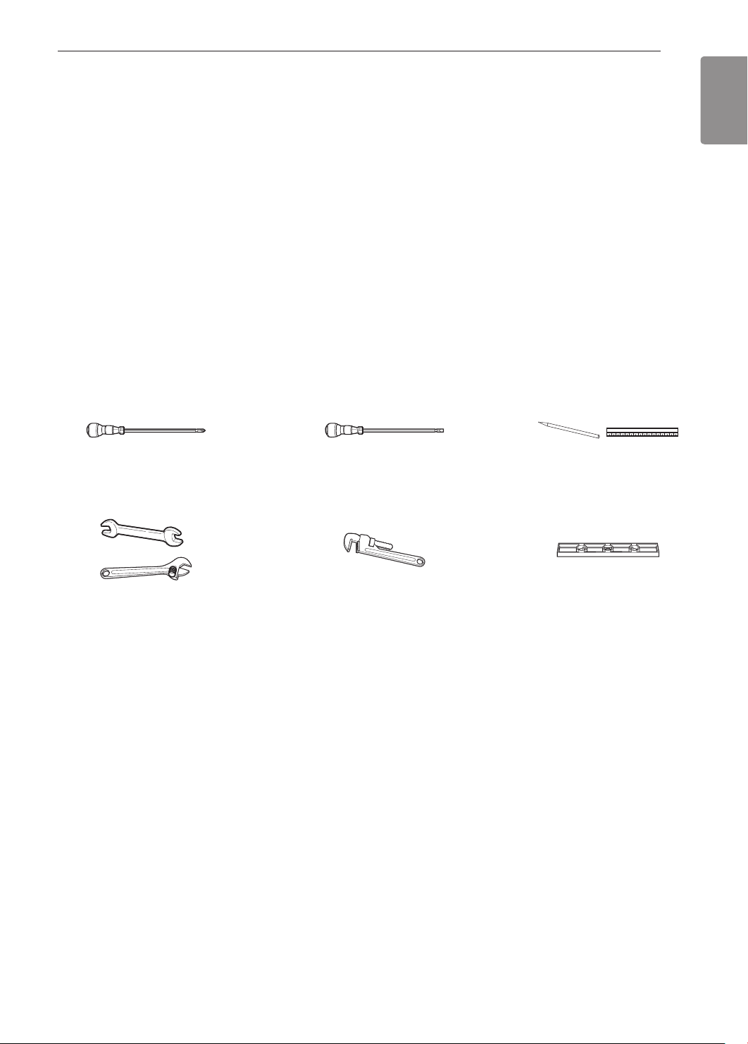
Tools Needed
Phillips screwdriver
Flat-blade screwdriver
Pencil and ruler
ENGLISH
Open-end or adjustable
wrench
Materials You May Need
•Gas line shut-off valve
•Pipe joint sealant that resists action of natural and LP gases
•Flexible metal appliance connector (
Never use an old connector when installing a new range.
•Flare union adapter for connection to gas supply line (
•Flare union adapter for connection to pressure regulator on range (
•Liquid leak detector or soapy water
•Lag bolt or
1
/2" O.D. sleeve anchor (for concrete floors only)
3
/4" or 1/2" NPT x 1/2" I.D.)
Pipe wrench (2)
(one for support)
3
/4" or 1/2" NPT x 1/2" I.D.)
1
/2" NPT x 1/2" I.D.)
Level
14
INSTALLATION
Installing the Range
Unpacking and Moving the Range
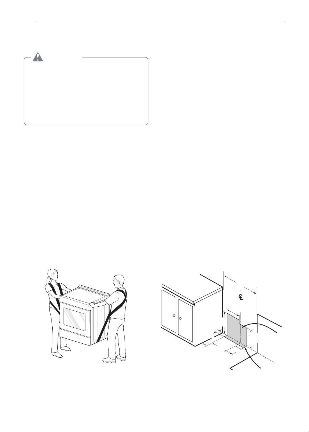
CAUTION
•You should use two or more people to move
and install the range. (Excessive Weight
Hazard) Failure to do so can result in back or
other injury.
•Do not use the door handles to push or
pull the range during installation or when
moving the range out for cleaning or
service. Doing so can result in serious damage
to the door of the range.
Remove packing material, tape and any temporary
labels from your range before using. Do not remove
any warning-type labels, the model and serial number
label, or the Tech Sheet that is located on the back of
the range.
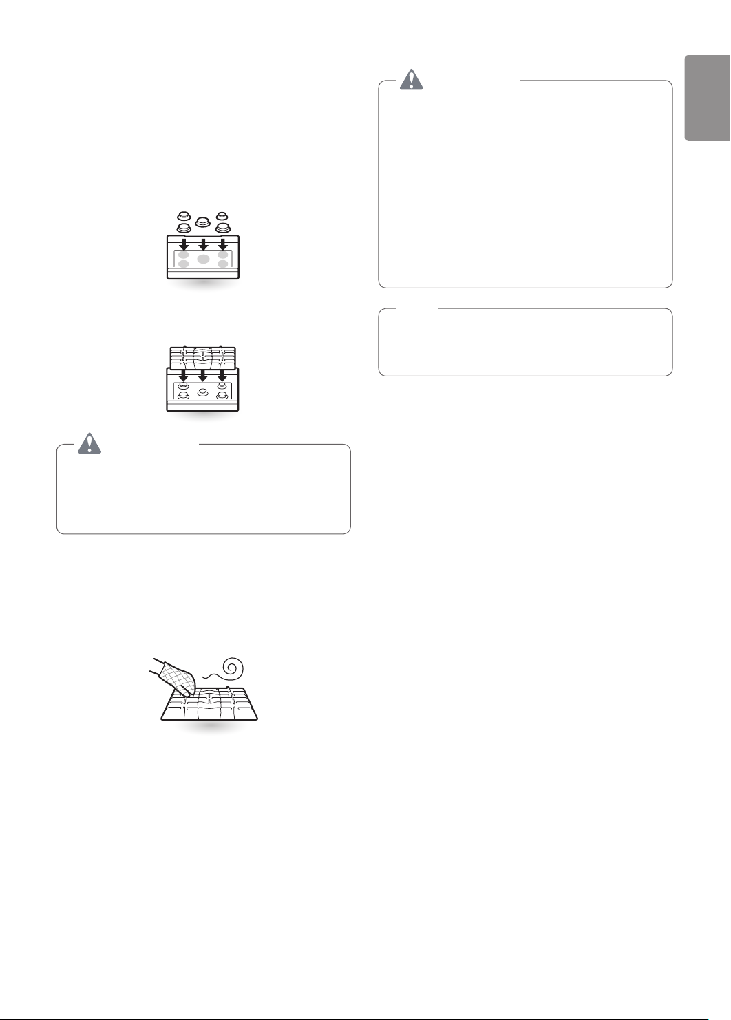
To remove any remaining tape or glue, rub the area
briskly with your thumb. Tape or glue residue can also
be easily removed by rubbing a small amount of liquid
dish soap over the adhesive with your fingers. Wipe
with warm water and dry.
Do not use sharp instruments, rubbing alcohol,
flammable fluids, or abrasive cleaners to remove tape
or glue. These products can damage the surface of
your range.
Your range is heavy and can be installed on soft
floor coverings such as cushioned vinyl or carpeting.
Use care when moving the range on this type of
flooring. Use a belt when moving the range to prevent
damaging the floor. Or slide the range onto cardboard
or plywood to avoid damaging the floor covering.
Choosing the Proper Location
Do not locate your range where it may be subject to
strong drafts. Any openings in the floor or wall behind
the range should be sealed. Make sure the openings
around the base of the range that supply fresh air
for combustion and ventilation are not blocked by
carpeting or woodwork.
Your range, like many other household units, is heavy
and can be installed on soft floor coverings such as
cushioned vinyl or carpeting. Use care when moving
the range on this type of flooring.
This appliance must not be installed with a ventilation
system that blows air downward toward the range.
This type of ventilation system may cause ignition and
combustion problems with the gas cooking appliance
resulting in personal injury or unintended operation.
When the floor covering ends at the front of the
range, the area that the range will be installed on
should be built up with plywood to the same level
or higher than the floor covering. This will allow the
range to be moved for cleaning and servicing, as well
as provide proper air flow to the range.
Also, make sure the floor covering can resist
temperatures of at least 167 °F (75 °C). See the
Installation Safety Instructions included in this
manual.
Make sure the wall coverings around your range
can resist the heat generated up to 194 °F (90 °C)
by the range. See the Installation Safety Instructions
included in this manual.
Gas Pipe and Electrical Outlet
Locations
(8.5 cm)
3"
(7.6 cm)
3
6/
11
13/
(30 cm)
"
16
17
15/
(45.6 cm)
16
16
"
"
30"
(76.2 cm)
7
14/
16
(20 cm)
5
"
14/
16
(15 cm)
"
(17 cm)
6
"
11/
16
INSTALLATION
15
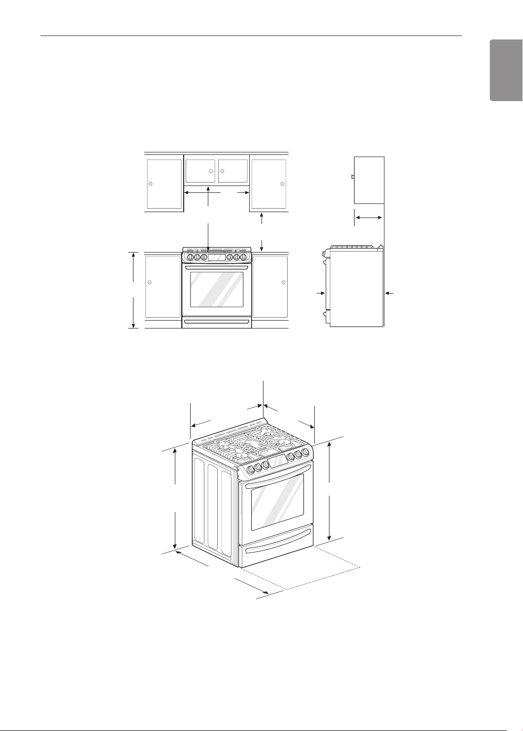
Dimensions and Clearances
Provide proper clearance between the range and adjacent combustible surfaces. These dimensions must be met
for safe use of your range. The location of the electrical outlet and pipe opening (see Gas Pipe and Electrical
Outlet Locations, page 14) may be adjusted to meet specific requirements. The range may be placed with 0"
clearance (flush) at the back wall.
Installation Clearances
Maximum
depth for
cabinets above
coutertops
Front edge of
/4"
the range side
panel forward
from cabinet
1
13"
0"
To cabinets
below
cooktop and
at the range
back
36"
(91.4 cm)
(76.2 cm)
30" (76.2 cm)
Minimum
30"
15"
(38.1 cm)
ENGLISH
Dimensions
Height
59
37
/64"
Depth with door open
43
7
29
/8"
(75.7 cm)
5
/32"
Depth with door closed
(includes door handle)
3
28
/4"
36
"
16
INSTALLATION
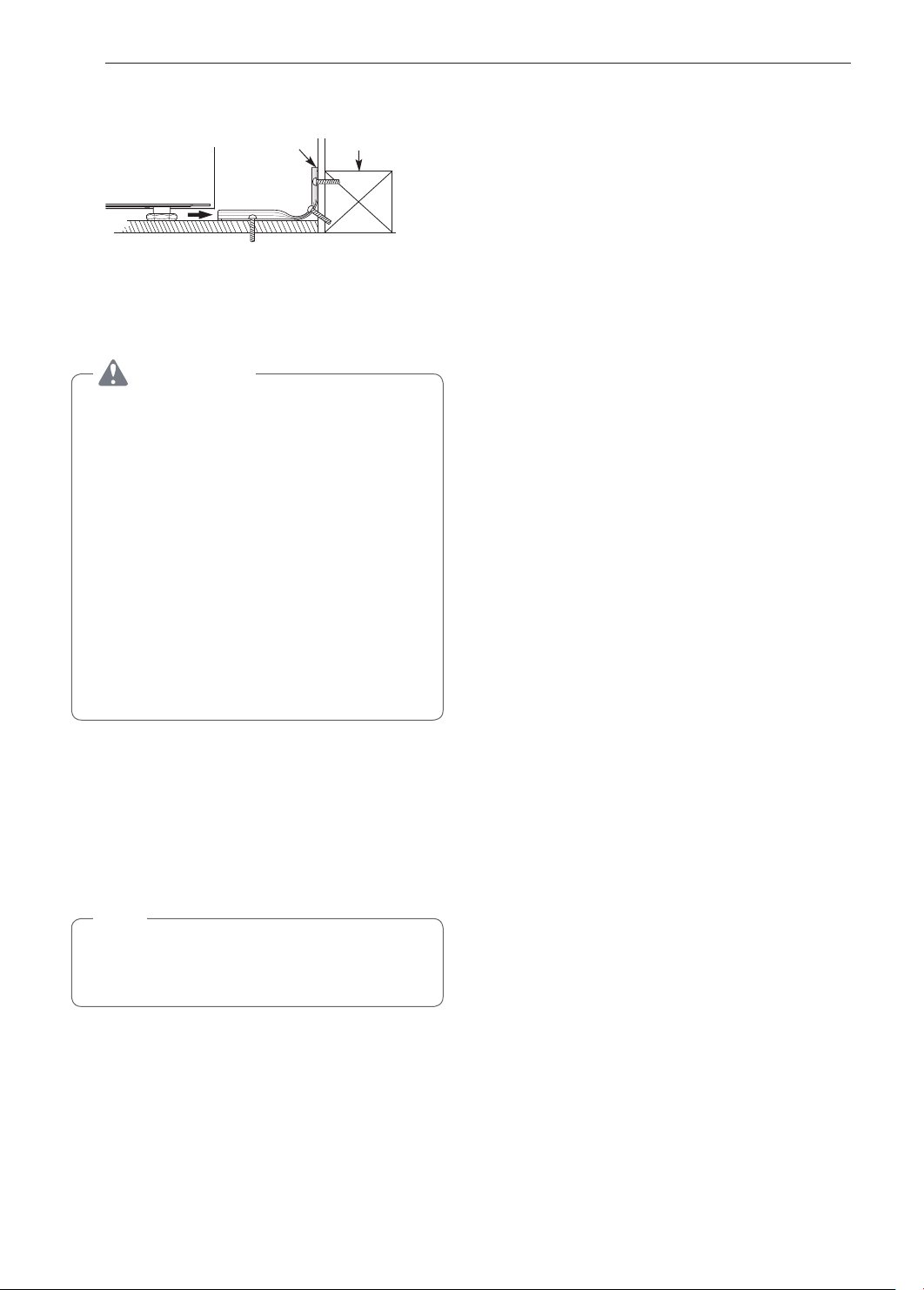
Installing the Anti-tip Device
Anti-tip
bracket
Screw must
enter wood or
concrete
The anti-tip bracket is packaged with an installation
template. The instructions include necessary
information to complete the installation. Read and
follow the range installation instruction sheet.
Wall plate
WARNING
•Range must be secured with an approved
anti-tip device.
•The range could be tipped by standing, sitting
or leaning on an open door if the range or
anti-tip device is not properly installed.
•After installing the anti-tip device, verify that it is
in place by carefully attempting to tilt the range
forward.
•This range has been designed to meet all
recognized industry tip standards for all normal
conditions.
•The installation of the anti-tip device must meet
all local codes for securing the appliance.
•The use of this device does not preclude tipping
of the range when not properly installed.
Optional Rear Filler
If the counter does not bridge the opening at the rear
wall the rear filler kit, that is provided with the slide in
range, will be needed.
Tighten the two lower screws on the rear
3
bracket. Insert one of the screws removed in
step 1 in the slot at each end of the rear filler.
Store the remaining two screws with these
4
instructions for future use.
Providing Adequate Gas
Supply
Your range is designed to operate at a pressure of
5" of water column on natural gas or 10" of water
column on LP.
Make sure you are supplying your range with the type
of gas for which it is configured.
This range is convertible for use on natural or LP gas.
When using this range on LP gas, conversion must
be made by a qualified LP installer before attempting
to operate the range.
For proper operation, the pressure of natural gas
supplied to the regulator must be between 5" and 13"
of water column.
For LP gas, the pressure supplied to the regulator
must be between 10" and 13" of water column. When
checking for correct operation of the regulator, the
inlet pressure must be at least 1" more than the
operating (manifold) pressure as given above.
The pressure regulator located at the inlet of the
range must remain in the supply line regardless of
which type of gas is being used.
A flexible metal appliance connector used to connect
the range to the gas supply line should have an I.D.
5
of
/8" and a maximum length of 5 feet. In Canada,
flexible connectors must be single wall metal
connectors less than 6 feet in length.
NOTE
If the countertop depth is greater than 25" there
will be a gap between the filler kit and the back
wall.
If the countertop depth is less than 24", the control
panel will not sit flush with the countertop.
Installing the Rear Filler
Using a screwdriver, remove the upper four
1
screws that attach the rear bracket and loosen
the lower two screws.
Place the rear filler on the rear bracket.
2
INSTALLATION
17
Connecting the Range to Gas
Shut off the range gas supply valve before removing
the old range and leave it off until the new hook-up
has been completed.
Because hard piping restricts movement of the range,
the use of a CSA International-certified flexible metal
appliance connector should be used unless local
codes require a hard-piped connection.
A manual valve shall be installed in an accessible
location in the gas piping external to the appliance
for the purpose of turning on or shutting off gas to the
appliance.
Never reuse an old connector when installing a new
range.
To protect against gas leaks, use a qualified pipe joint
sealant on all external threads.
Install a male 1/2" or 3/4" flare union adapter to the
1
NPT internal thread of the manual shut-off valve,
taking care to back-up the shut-off valve to keep
it from turning.
Install a male 1/2" flare union adapter to the 1/2"
2
NPT internal thread at the inlet of the pressure
regulator. Use a backup wrench on the pressure
regulator fitting to prevent damage.
WARNING
•Do not use a flame to check for gas leaks.
•Isolate the range from the gas supply system
by closing its individual shut-off valve during
any pressure testing of the gas supply system
at test pressures equal to or less than
(3.5 kPa).
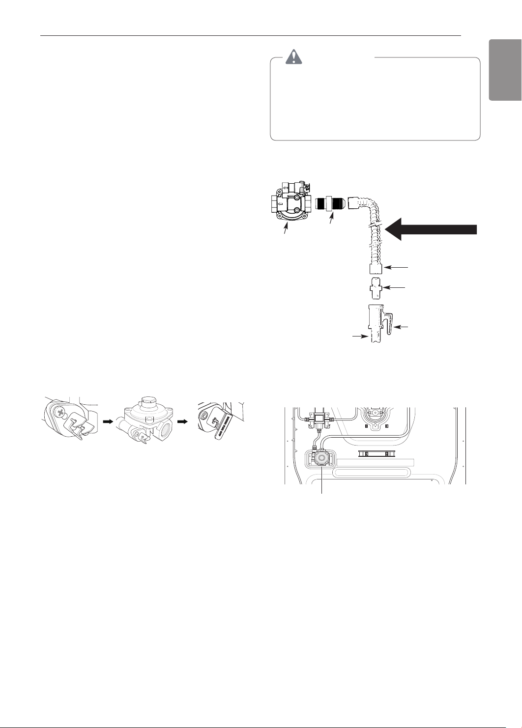
Flexible Connector Hookup
1
Adapter
/2"
Pressure regulator
1
/2" or 3/4" Gas
pipe
Gas Flow into Range
Flex connector
(6 ft. max.)
Adapter
Gas shut-off
valve
1
/2" psig
ENGLISH
In an emergency situation or if you want to shut
off the gas supply, close the regulator valve by
positioning the lever as shown in the figure below.
Lever’s open
position
Connect a flexible metal appliance connector to
3
the adapter on the range. Position the range to
permit connection at the shut-off valve.
When all connections have been made, be sure
4
all range controls are in the Off position and turn
on the main gas supply valve. Gas leaks may
occur in your system and create a hazard. Gas
leaks may not be detected by smell alone.
Check all gas connection joints and fittings for
leaks with a non-corrosive leak detection fluid,
then wipe off.
Gas suppliers recommend you purchase and
install a UL approved gas detector. Install
and use in accordance with the installation
instructions.
Lever’s closed
position
Installer: Inform the consumer of the location of the gas
shutoff valve
Pressure Regulator Position
.
Pressure Regulator
18
INSTALLATION
Electrical Connections
Electrical Requirements
120 Volt, 60 Hz, properly grounded dedicated circuit
protected by a 15 or 20 Amp circuit breaker, or slow
blow fuse.
If an external electrical source is utilized, the
appliance, when installed, must be electrically
grounded in accordance with local codes or, in the
absence of local codes, with the National Electrical
Code, ANSI/NFPA 70.
Grounding
IMPORTANT: FOR PERSONAL SAFETY, THIS
APPLIANCE MUST BE PROPERLY GROUNDED.
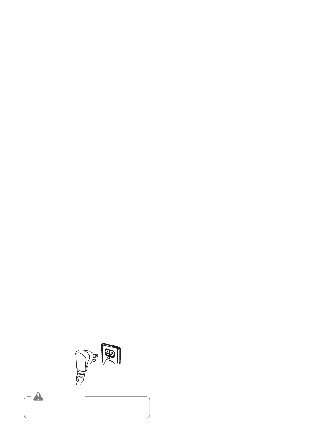
The power cord of this appliance is equipped with
a 3-prong (grounding) plug which mates with a
standard 3-prong grounding wall receptacle to
minimize the possibility of electric shock hazard from
this appliance.
The customer should have the wall receptacle and
circuit checked by a qualified electrician to make sure
the receptacle is properly grounded.
Where a standard two-prong wall receptacle is
encountered, it is the personal responsibility and
obligation of the customer to have it replaced with a
properly grounded three-prong wall receptacle.
DO NOT, UNDER ANY CIRCUMSTANCES, CUT OR
REMOVE THE THIRD (GROUND) PRONG FROM
THE POWER CORD.
A word about GFCI’s – GFCI’s are not required or
recommended for gas range receptacles.
Ground Fault Circuit Interrupters (GFCI’s) are
devices that sense leakage of current in a circuit
and automatically switch off power when a threshold
leakage level is detected. These devices must
be manually reset by the consumer. The National
Electrical Code requires the use of GFCI’s in kitchen
receptacles installed to serve countertop surfaces.
Performance of the range will not be affected
if operated on a GFCI-protected circuit but the
occasional resetting of the circuit can become an
annoyance.
Do not use an adapter plug. Disconnecting of the
power cord places undue strain on the adapter
and leads to eventual failure of the adapter ground
terminal.
Installation must conform with local codes or, in the
absence of local codes, with the National Fuel Gas
Code, ANSI Z223.1/NFPA 54.
The installation of appliances designed for mobile
home installation must conform with the Manufactured
Home Construction and Safety Standard, Title 24
CFR, Part 3280 (formerly the Federal Standard
for Mobile Home Construction and Safety, Title
24, HUD, Part 280) or, when such standard is not
applicable, the Standard for Manufactured Home
Installations, latest edition (Manufactured Home Sites,
Communities and Set-Ups), ANSI A225.1, latest
edition, or with local codes. In Canada, mobile home
installation must be in accordance with the current
CAN/CSA Z240/MH Mobile Home Installation Code.
Sealing the Openings
Seal any openings in the wall and floor after electrical
and gas supplies are completed.
Preferred
Method
Ensure proper ground
exists before use
CAUTION
Have the circuit checked by a qualified electrician
to make sure the receptacle is properly grounded.
INSTALLATION
19
Assembling the Surface
Burners
CAUTION
Do not operate the burners without all parts in
place.
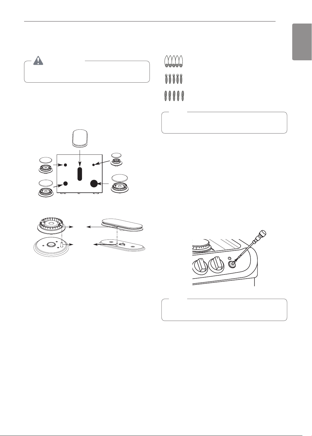
Place the burner caps and heads on the cooktop.
Make sure that the caps and heads are placed in the
correct locations. There is one small, one medium,
one large, one oval(center), and one extra large
burner head and cap.
Center Burner
Oval (Center) burner
head/cap assembly
Medium
burner
head
and cap
Large burner
head and cap
Front of range
Hole
Extra large burner
Small burner
head and
cap
head and cap
Quality of Flames
The combustion quality of the burner flames needs to
be confirmed visually.
A Yellow flames - Call for service.
B Yellow tips on outer cones - This
is normal for LP gas.
C Soft blue flames - This is normal
for natural gas.
NOTE
•With LP gas, some yellow tipping on outer
cones is normal.
Adjusting the Surface Burner to the
Low Flame (Simmer) Setting
Light all surface burners.
1
Turn the knob on the burner being adjusted to
2
Lo.
Remove the knob.
3
Insert a small, flat-blade screwdriver into the
4
valve shaft.
ENGLISH
Electrode
Make sure the hole in the burner head is positioned
over the electrode.
Checking Ignition of the
Surface Burners
Electric Ignition
Select a surface burner knob and simultaneously
push in and turn to the Lite position. You will hear
a clicking sound indicating proper operation of the
spark module.
Once the air has been purged from the supply lines
the burner should ignite within 4 seconds. After the
burner ignites, rotate the knob out of the Lite position.
Try each burner in succession until all burners have
been checked.
NOTE
Hold the valve shaft with one hand while turning
the screw to adjust with the other.
Replace the knob.
5
Test the flame stability.
6
Test 1: Turn the knob from Hi to Lo quickly. If the
flame goes out, increase the flame size and test
again.
Test 2: With the burner on a Lo setting, open
and close the oven door quickly. If the flame is
extinguished by the air currents created by the
door movement, increase the flame height and
test again.
Repeat steps 1-6 for each surface burner.
7
20
INSTALLATION
Checking Operation of Bake / Broil
Burners
To check ignition of the Bake burner, follow the steps
below:
Remove all packing materials from inside the
1
oven cavity.
Turn oven mode knob to select Bake. 350 °F
2
appears in the display.
Press Start.
3
It may take between 30 and 90 seconds for the
burner to start heating.
To check ignition of the Broil burner, follow the steps
below:
Turn oven mode knob to select Broil High. Hi
1
appears in the display.
Make sure the door is closed.
2
Press Start.
3
It may take between 30 and 90 seconds for the
burner to start heating.
NOTE
Do not try to light either the Bake or Broil burners
during a power outage. The range has an
electrical ignition system and cannot be used
without power.
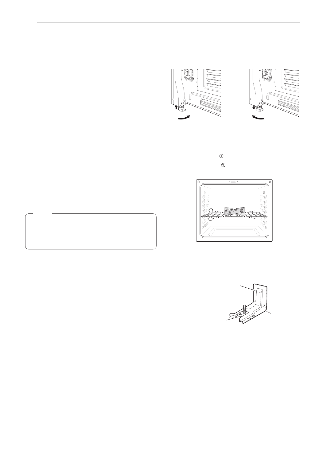
Leveling the Range
Level the range by adjusting the leveling legs.
Extending the legs slightly may also make it easier to
insert the rear leg into the anti-tip bracket.
Use a level to check your adjustments. Place the level
diagonally on the oven rack, and check each direction
for level.
First check direction
Then check direction
on the rack, adjust the leveling legs.
.
. If the level doesn’t show level
2
1
Adjusting Air Shutters (for LP
Conversions)
The range comes from the factory with the air
shutters adjusted for proper air flow for natural gas.
If converted to LP, follow the instructions provided in
the conversion kit to properly adjust the air shutters.
LP conversion must be performed by a qualified
technician.
Engaging the Anti-tip Device
Anti-tip
bracket
Leveling leg
Slide the range against the wall, making sure
1
the back leg slides into and engages the anti-tip
bracket.
Check for proper installation by grasping
2
the front edge of the cooktop and carefully
attempting to tilt the range forward.
OPERATION
21
OPERATION
Gas Surface Burners
Before Use
Read all instructions before using.
Make sure that all burners are properly placed.
Make sure that all grates are properly placed
before using the burner.
CAUTION
Do not operate the burner for an extended period
of time without cookware on the grate.
The finish on the grate may chip without cookware
to absorb the heat.
CAUTION
ENGLISH
WHAT TO DO IF YOU SMELL GAS
•Open windows.
•Do not try to light any appliance.
•Do not touch any electrical switch.
•Do not use any phone in your building.
•Immediately call your gas supplier from a
neighbor’s phone. Follow the gas supplier’s
instructions.
•If you cannot reach your gas supplier, call the
fire department.
NOTE
Electric spark igniters from the burners cause
a clicking noise. All the spark igniters on the
cooktop will activate when igniting just one burner.
Make sure the burners and grates are cool before
touching them, or placing a pot holder, cleaning
cloth, or other materials on them.
Touching grates before they cool down may cause
burns.
 Loading...