

LG LSCG306ST/01, LSCG307ST/00, LSCG366ST/01, LSCG367ST/00, LSCG306ST/00 Installation Guide

ENGLISH
ESPAÑOL
INSTALLATION MANUAL
GAS COOKTOP
Please read this guide thoroughly before installation.
LSCG366ST
LSCG306ST
MFL62725504_05
LSCG367ST
LSCG307ST
Copyright © 2012 - 2017 LG Electronics Inc. All Rights Reserved.
www.lg.com
2
INSTALLATION INSTRUCTIONS
INSTALLATION SAFETY INSTRUCTIONS
BEFORE YOU BEGIN
Read these instructions completely
and carefully.
Installation of this cooktop must conform with local
codes, or in the absence of local codes, with the
National Fuel Gas Code, ANSI Z223.1/NFPA.54,
latest edition. In Canada, installation must conform
with the current Natural Gas Installation Code,
CAN/CGAB149.1 or the current Propane
Installation Code, CAN/CGA-B149.2, and with
local codes where applicable. This cooktop has
been design-certified by CSA International
according to ANSI Z21.1, latest edition and
Canadian Gas Association according to
CAN/CGA-1.1 latest edition.
As with any appliance using gas and generating
heat, there are certain safety precautions you
should follow. You will find these precautions in the
lmportant Safety Information section in your User’s
Guide. Read them carefully.
• IMPORTANT – Save these instructions for
local electrical inspector’s use.
• IMPORTANT – Observe all governing
codes and ordinances.
Note to Installer: Leave these instructions with
the appliance after installation is completed.
Note to Consumer: Keep the User’s Guide and
Installation Instructions for future reference.
NOTE: This appliance must be properly
grounded.
• The electrical diagram is in an envelope attached
to the back of the cooktop.
• Skill level – Installation of this appliance requires
basic mechanical skills.
• Proper installation is the responsibility of
theinstaller.
• Product failure due to improper installation is not
covered under the Warranty.
• Remove all tape and packaging.
• Make sure the burners are properly seated and
level.
• Take the accessory pack off of the cooktop
• Check to be sure that no cooktop parts have
come loose during shipping.
3
ENGLISH
INSTALLATION INSTRUCTIONS
READ ALL INSTRUCTIONS BEFORE INSTALLATION
IN THE COMMONWEALTH OF MASSACHUSETTS
• This product must be installed by a licensed
plumber or gas fitter.
• When using ball type gas shut-off valves, they shall
be the T-handle type.
• A flexible gas connector, when used, must not
exceed 3 feet in length.
FOR YOUR SAFETY
WHAT TO DO IF YOU SMELL GAS
WARNING:
this manual is not followed exactly, a fire or
explosion may result causing property damage,
personal injury or death.
– Do not store or use combustible materials,
gasoline or other flammable vapors and
liquids in the vicinity of this or any other
appliance.
If the information in
• Do not try to light any appliance.
• Do not touch any electrical switches,
• Do not use any phone in your building.
• Immediately call your gas supplier from a
neighbor′s phone. Follow the gas supplier
instructions.
• If you cannot contact your gas supplier, call
the fire department.
PREPARING FOR INSTALLATION
Installation and service must be performed by
a qualified installer, service agency or the gas
supplier.
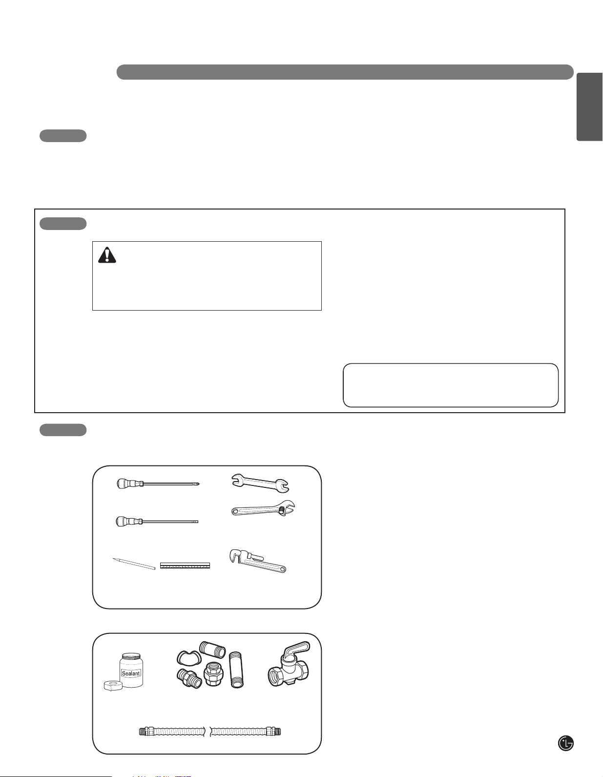
TOOLS YOU WILL NEED
Phillips screwdriver
Flat-blade screwdriver
Pencil and ruler
adjustable wrench
(one for support)
MATERIALS YOU MAY NEED
Joint
Sealant
Pipe Fittings
Open-end or
Pipe wrench(2)
Shut Off
Valve
MATERIALS YOU MAY NEED
• Gas line shut-off valve
• To reduce the possibility of gas leaks, apply teflon
tape or a thread compound approved for use with
LP or Natural gases to all threaded connections.
• Flexible metal appliance connector (5/8” I.D.)
A 3-foot length is recommended for ease of
installation but other lengths are acceptable.
Never use an old connector when installing a new
cooktop.
• Flare union adapter for connection to gas supply
line (3/4” or 1/2” NPT x 5/8” I.D.)
• Flare union adapter for connection to pressure
regulator on cooktop. (1/4” NPT x 1/2” I.D.)
• Liquid leak detector or soapy water.
Flexible Connector
4
INSTALLATION INSTRUCTIONS
INSTALLATION SAFETY INSTRUCTIONS
BEFORE YOU BEGIN
Remove all tape and packing materials before using the cooktop. Dispose all plastic bags after
unpacking the cooktop. Never allow children to play with packing materials.
IMPORTANT SAFETY INSTRUCTIONS
Read these instructions completely and carefully. Improper installation, adjustment, alteration,
service or maintenance can cause injury or property damage.
For assistance or additional information, consult a qualified installer, service agency, manufacturer
(dealer) or your gas supplier.
Never reuse old flexible connectors. The use of old flexible connectors can cause gas leaks and
personal injury. Always use NEW flexible connectors when installing a gas appliance.
This is the safety alert symbol. This symbol alerts you to potential hazards that can kill
or hurt you and others. All safety messages will follow the safety alert symbol and either
the word “ WARNING” or “CAUTION”.
WARNING
CAUTION
IMPORTANT: Remove all packing material and
literature before connecting gas and electrical
supply.
• Have your cooktop installed by a qualified installer.
• Your cooktop must be electrically grounded in
accordance with local codes or, in the absence of
local codes, in accordance with the National
Electrical Code (ANSI/NFPA 70, latest edition). In
Canada, electrical grounding must be in
accordance with the current CSA C22.1 Canadian
Electrical Code Part 1 and/or local codes.
Refer to 3. Electrical Connections, in this manual.
This symbol will alert you to hazards or unsafe practices which could
cause serious bodily harm or death.
This symbol will alert you to hazards or unsafe practices which could
cause bodily injury or property damage.
• Be sure the wall coverings around the cooktop can
withstand heat generated by the cooktop up to
200 °F.
• Avoid placing cabinets above the cooktop.
To minimize the hazard caused by reaching over
the open flames of operating burners, install a
ventilation hood over the cooktop that projects
forward at least 5” beyond the front of the cabinets.
5
ENGLISH
INSTALLATION INSTRUCTIONS
INSTALLATION SAFETY INSTRUCTIONS
• The ventilating hood must be constructed of sheet
metal not less than 0.0122” thick. Install above the
cooktop with a clearance of not less than 1/4”
between the hood and the underside of the
combustible material or metal cabinet. The hood
must be at least as wide as the appliance and
centered over the appliance. Clearance between
the cooking surface and the ventilation hood
surface MUST NEVER BE LESS THAN 24
INCHES.
EXCEPTION: Installation of a listed microwave
oven or cooking appliance over the cooktop shall
conform to the installation instructions packed with
that appliance.
• If cabinets are located above the cooktop, allow a
minimum clearance of 30” between the cooking
surface and the bottom of unprotected cabinets.
• If a 30” clearance between cooking surface and
overhead combustible material or metal cabinets
cannot be maintained, protect the underside of the
cabinets above the cooktop with not less than 1/4”
insulating millboard covered with sheet metal not
less than 0.0122” thick. Clearance between the
cooking surface and protected cabinets MUST
NEVER BE LESS THAN 24 INCHES.
• The vertical distance from the plane of the cooking
surface to the bottom of adjacent overhead
cabinets extending closer than 1” to the plane of
the cooktop sides must not be less than 18”. (See
the Dimensions and Clearances illustration in this
manual.)
• Do not abstruct the combustion or ventilation air.
• Leak testing of the appliance shall be conducted
according to the manufacturer’s instructions.
CAUTION: Items of interest to
children should not be placed in cabinets above
the cooktop.
- children climbing on the cooktop to reach items
could be seriously injured.
WARNING: This appliance must
not be installed with a ventilation system that
blows air downward toward the cooktop. This
type of ventilation system may cause ignition
and combustion problems with the gas cooking
appliance resulting in personal injury or unintended
operation.
(continued)
6
INSTALLATION INSTRUCTIONS
A
A
C
L
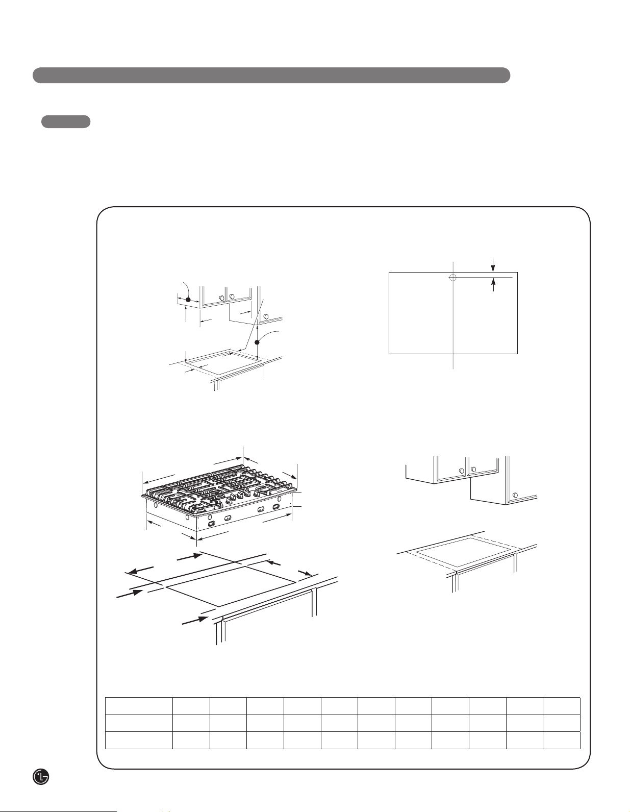
DIMENSIONS AND CLEARANCES
Provide enough clearances between the cooktop and
adjacent combustible surfaces. These dimensions
must be met for safe use of your cooktop.
The location of the electrical outlet and pipe opening
may be adjusted to meet specific requirements.
1. MAINTAIN THE FOLLOWING
MINIMUM CLEARANCE
DIMENSIONS
13˝MAX. Depth of unprotected
overhead cabinets
30˝ MIN. clearance
from countertop to
unprotected overhead
surface
A˝ MIN. clearance
from cutout to side
wall on the left of
unit.
B″MIN
A˝ MIN. clearance from
cutout to side wall on
the right of the unit
18˝ MIN. height
from countertop
to nearest cabinet
on either side of
unit
2. COOKTOP AND CUTOUT
DIMENSIONS
C
width
D
depth
The cooktop may be placed with 2 3/4” clearance to
the back wall.
3. RECOMMENDED GAS SUPPLY
LOCATION FROM BACKWALL
1” Min. From Backwall
Recommended
gas supply
location
From Cutout
Center Line
4. MAKE SURE WALL COVERINGS,
COUNTERTOP AND CABINETS
AROUND COOKTOP CAN
WITHSTAND HEAT(UP TO 200℉)
GENERATED BY COOKTOP
Wall covering ,
cabinets and
counterto p
must withstan d
heat up to
200°F
G
depth
H
width cut
E
height
F
width
J
depth cut
L
L″ MIN.
Between
cutout
and the wall
behind the
cooktop
K
K″ MIN.
From front
edge of cutout
and front edge
of countertop
To ensure accuracy, it is best to make
a template when cutting the opening
in the counter
MODEL A B C D E F G H J K L
30″ Cooktop 11
36″ Cooktop 11
13
/
″ 30″ 30″ 21
16
13
/
″ 36″ 36″ 21
16
11
/
11
/
″ 3
16
″ 3
16
3
/
″ 28
4
3
/
″ 33
4
1
/
″ 19
4
5
/
″ 19
8
3
/
″ 28
8
3
/
″ 33
8
1
15
/
″ 19
2
/
″ 19
16
11
/
11
/
″ 1
16
″ 1
16
5
/
″ 2
8
5
/
″ 2
8
3
/
″
4
3
/
″
4
7
ENGLISH
INSTALLATION INSTRUCTIONS
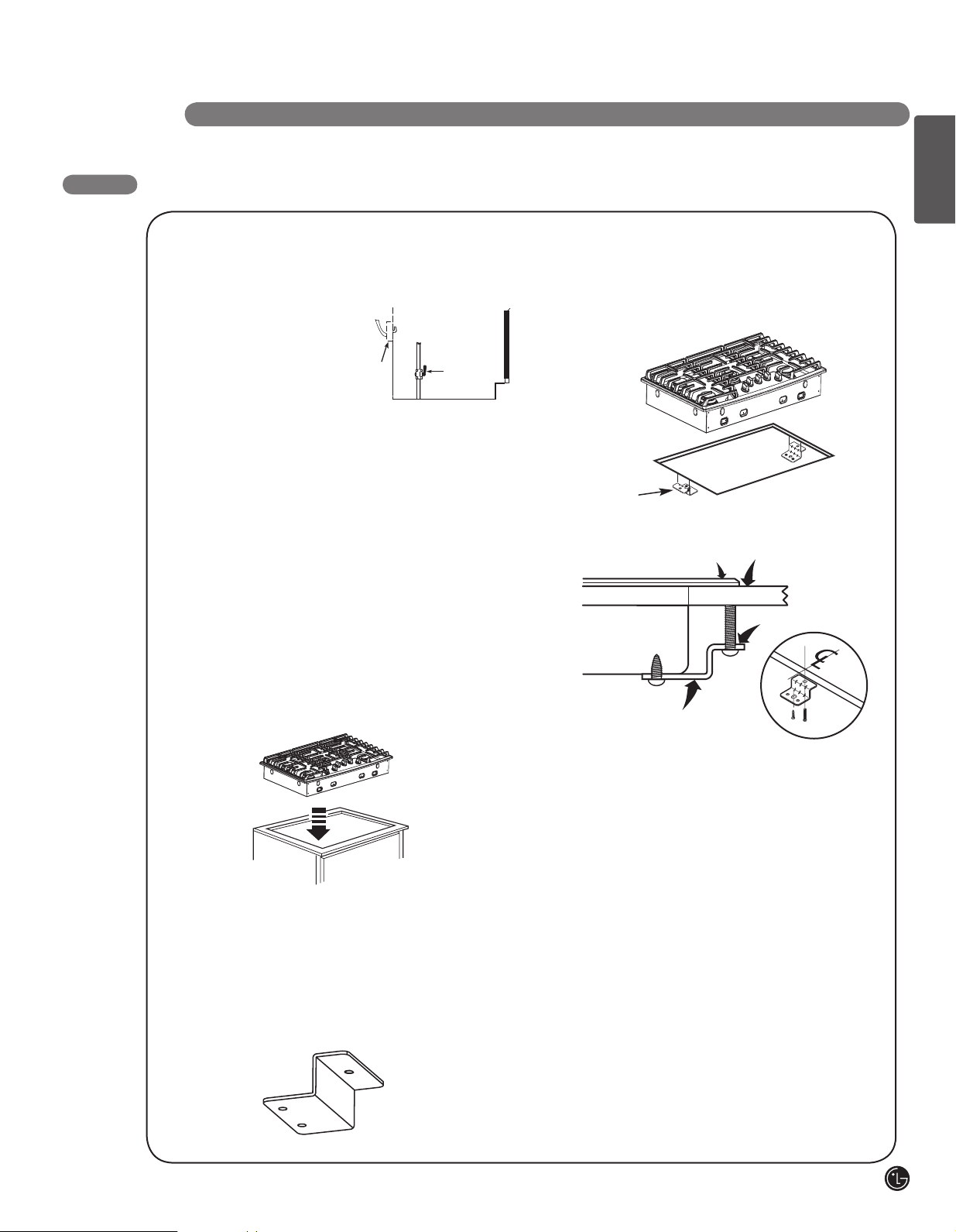
INSTALLING THE COOKTOP UNIT
1. LOCATE ELECTRICAL OUTLET
AND GAS SHUT-OFF VALVE
BENEATH CABINET
NEVER RE-USE
OLD FLEX
CONNECTORS.
Electrical
outlet 12˝
below
countertop
Shut-Off
valve
Install a manual shut-off valve in the gas line
in an easily accessible location outside the
cooktop. Be sure you know how and where to
shut off the gas supply to the cooktop. Install
the electrical outlet 12˝ below the countertop.
2. INSERT COOKTOP INTO CUTOUT
Install a manual shut-off valve in the gas line
in an easily accessible location outside the
cooktop. Be sure you know how and where to
shut off the gas supply to the cooktop. Install
the electrical outlet 12˝ below the countertop.
4. INSTALL THE RETAINER BRACKETS
Install the retainer brackets to the bottom
of the cooktop unit. then snug the bolts
against the bottom of the countertop as
shown
Retainer brackets
Cooktop
Retainer brackets
Countertop
Screw
3. LOCATE RETAINER BRACKETS
Remove the retainer brackets from the
literature package.
NOTE: The retainer brackets MUST be
installed to meet local codes or, in their
absence, with the National Electrical Code
ANSI/NFPA No. 70, latest edition.

8
INSTALLATION INSTRUCTIONS
1. PROVIDE ADEQUATE GAS SUPPLY
This cooktop is designed to operate at a pressure of
5” of water column on natural gas or 10” of water
column on LP, propane or butane gas.
Make sure you are supplying your cooktop with the
type of gas for which it is designed.
This cooktop is convertible for use on natural or
propane gas. When using this cooktop on LP gas,
conversion must be made by a qualified LP installer
before attempting to operate the cooktop on that gas.
For correct operation, the pressure of natural gas
supplied to the regulator should be between 5” and
13” of water column.
For LP gas, the pressure supplied must be between
10” and 13” of water column.
When checking for correct operation of the regulator,
the inlet pressure must be at least 1” more than the
operating -manifold- pressure as given above.
The pressure regulator located at the inlet of the
cooktop manifold must remain in the supply line
regardless of whether natural or LP gas is being
used.
A flexible metal appliance connector used to connect
the cooktop to the gas supply line must have an I.D.
of 5/8” and can be 3 feet max. in length for easy
installation. In Canada, flexible connectors should be
single wall metal connectors less than 6 feet in
length.
2. CONNECT THE COOKTOP TO GAS
Shut off the main gas supply valve before removing
the old cooktop and leave it off until the new hook-up
has been completed. Don’t forget to relight the pilot on
other gas appliances when you turn the gas back on.
Because hard piping restricts movement of the
cooktop, the use of a CSA International-certified
flexible metal appliance connector is recommended
unless local codes require a hard-piped connection.
Never reuse an old connector when installing a new
cooktop. If the hard piping method is used, you must
carefully align the pipe; the cooktop cannot be
moved after the connection is made.
To prevent gas leaks, put pipe joint compound on, all
male -external- pipe threads.
Install a manual gas line shut-off valve in the gas
1
line in an easily accessed location outside of the
cooktop. Be sure everyone operating the cooktop
knows where and how to shut off the gas supply
to the cooktop.
Install male 1/2” flare union adapter to the 1/2”
2
NPT internal thread at inlet of pressure regulator.
Use a backup wrench on the pressure regulator
fitting to prevent damage.
Install male 1/2” or 3/4” flare union adapter to the
3
NPT internal thread of the manual shut-off valve,
taking care to back-up the shut-off valve to keep
it from turning.
Connect a flexible metal connector to the adapter
4
on the cooktop. Position the cooktop to permit
connection at the shut-off valve.
When all connections have been made, be sure
5
all cooktop controls are in the off position and
turn on the main gas supply valve.
Check for gas leaks by using manometer.
If a manometer is not available, turn the gas
supply on to the cooktop on and use a liquid leak
detector at all joints and connections to check for
leaks.
Tighten all connections, if necessary, to prevent
gas leakage in the cooktop or supply line.
WARNING!:
DO NOT USE A FLAME TO CHECK FOR GAS LEAKS.
Disconnect the cooktop and its individual shut-off
valve from the gas supply piping system during any
pressure testing of that system at test pressures
more than 1/2 psig(3.5kPa).
Isolate the cooktop from the gas supply piping
system by closing its individual shut-off valve during
any pressure testing of the gas supply system at test
pressures equal to or less than 1/2 psig(3.5kPa)
9
ENGLISH
INSTALLATION INSTRUCTIONS
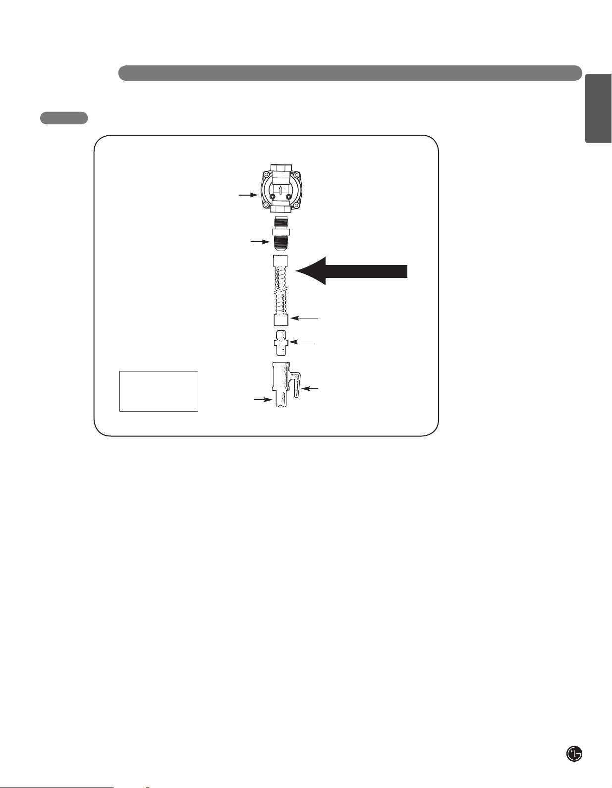
FLEXIBLE CONNECTOR HOOKUP
Pressure
regulator
Adapter
Gas Flow into Range
Flex
connector
(6 ft. max.)
Adapter
Installer: Inform the
consumer of the
location of the gas
shut-off valve.
1/2” or 3/4”
Gas pipe
Gas
shut-off valve
10
INSTALLATION INSTRUCTIONS
3. ELECTRICAL CONNECTIONS
ELECTRICAL REQUIREMENTS
120 Volt, 60 Hertz, properly grounded dedicated
circuit protected by a 15 A or 20 A circuit breaker or
time delay fuse.
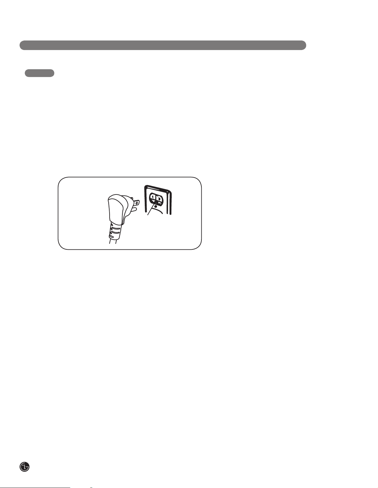
GROUNDING
IMPORTANT: FOR PERSONAL SAFETY,
THIS APPLIANCE MUST BE PROPERLY
GROUNDED.
PREFERRED
METHOD
Ensure proper ground
exists before use
The power cord of this appliance should be equipped
with a three-prong (grounding) plug which mates with
a standard three-prong grounding wall receptacle to
reduce the possibility of electric shock hazard from
this appliance.
The customer should have the wall receptacle and
circuit checked by a qualified technician to be sure
the receptacle is properly grounded.
When connecting the cord of this cooktop to a
standard two-prong wall receptacle, it is the personal
responsibility and obligation of the customer to have
it replaced with a properly grounded three-prong wall
receptacle.
DO NOT, UNDER ANY CIRCUMSTANCES, CUT OR
REMOVE THE THIRD (GROUND) PRONG FROM
THE POWER CORD.
A word about Ground Fault Circuit Interrupters –
Ground Fault Circuit Interrupters are not required or
recommended for gas range receptacles.
Ground Fault Circuit Interrupters are devices that
sense leakage of current in a circuit and
automatically switch off power when a threshold
leakage level is detected.
These devices must be manually reset by the
customer.
The National Electrical Code requires the use of
Ground Fault Circuit Interrupters in kitchen
receptacles installed to serve countertop surfaces.
Performance of the cooktop will not be affected if it is
operated from a Ground Fault Circuit Interrupters
protected circuit but occasional nuisance can occur.
 Loading...